Coordinated Control of the Energy Router-Based Smart Home Energy Management System


1
School of Electrical and Information Engineering, Tianjin University, Tianjin 300072, China
2
State Grid Chongqing Electric Power CO., Electric Power Research Institute, Chongqing 401120, China
*
Author to whom correspondence should be addressed.
Appl. Sci. 2017, 7(9), 943; https://0-doi-org.brum.beds.ac.uk/10.3390/app7090943
Submission received: 2 August 2017
/
Revised: 3 September 2017
/
Accepted: 12 September 2017
/
Published: 13 September 2017
(This article belongs to the Special Issue Smart Home and Energy Management Systems)
Abstract
:Home area energy networks will be an essential part of the future Energy Internet in terms of energy saving, demand-side management and stability improvement of the distribution network, while an energy router will be the perfect choice to serve as an intelligent and multi-functional energy interface between the home area energy network and power grid. This paper elaborates on the design, analysis and implementation of coordinated control of the low-voltage energy router-based smart home energy management system (HEMS). The main contribution of this paper is to develop a novel solution to make the energy router technically feasible and practical for the HEMS to make full use of the renewable energy sources (RESs), while maintaining “operational friendly and beneficial” to the power grid. The behaviors of the energy router-based HEMS in correlation with the power grid are investigated, then the coordinated control scheme composed of a reference voltage and current compensation strategy and a fuzzy logic control-based power management strategy is developed. The system model is built on the MATLAB/Simulink platform, simulation results have demonstrated that the presented control scheme is a strong performer in making full use of the RES generations for the HEMS while maintaining the operational stability of the whole system, as well as in collaboration with the power grid to suppress the impact of RES output fluctuations and load consumption variations.
1. Introduction
Increasing amounts of renewable energy sources (RESs), such as solar and wind, are required to be integrated into the electrical power grid, driven by the growing energy consumption demand as well as the concern for environmental protection. As a consequence, the power distribution network is shifting from a centralized energy supply system with a hierarchical framework to a multi-sourced, meshed network of the next generation—the Energy Internet [1,2]. Emerging technologies in the areas of active distribution network [3,4,5], microgrid [6,7,8] and smart home energy management [9,10,11] are being developed rapidly to meet the requirements of the Energy Internet, in which energy production, distribution and consumption as well will all be scheduled and managed in a unified and optimal manner [1].
Flexible and bidirectional energy flow in the distribution network will be a symbolic feature of the Energy Internet, since microgrids and home area energy networks will play the dual roles of energy consumption and production. As the basic energy presumption unit, a home area energy network will be an essential part in the Energy Internet in terms of energy saving and management due to the following reasons: (1) residential and commercial buildings account for a considerable amount, e.g., up to 50% in Europe, of the total energy consumption [12]; (2) enormous amounts of RESs, especially those small scale distributed generations (DGs) will be integrated into the power grid through home area energy networks; and (3) these numerous and widely allocated DGs will have critical influence on the distribution network due to the stochastic and intermittent nature of the RESs [13,14]. Meanwhile, these DGs can also have comprehensive interactions with the grid, which can be used to improve power quality, energy efficiency and system stability of the distribution network.
For energy prosumers at residential level with RES units of several kW capacity, an energy storage system (ESS), and perhaps electric vehicles (EVs) with feedback functionality, they can benefit the power grid in several aspects: (1) the total power generation and power transfer loss on the grid side can be reduced considerably; (2) with the introduction of flexible tariff on electric power, energy prosumers are encouraged to cooperate with the power grid to reduce the peak load [15]; (3) energy prosumers are capable of suppressing the impact of the RES output fluctuations and load consumption variations to the grid, by optimally scheduling the operations of their ESSs and EVs; and (4) meanwhile, a prosumer can cooperate with another neighbors in order to achieve better global performance and reliability within the residential microgrids [16]. Therefore, there is an urgent need to develop efficient and flexible methods for smart home energy management.
Many works have been conducted in the field of smart home energy management, aiming to meet the requirements for DGs deployment in large scale. In paper [17], a home energy management scheduling controller of the residential demand response strategy was developed by using hybrid lightning search algorithm-based artificial neural network to predict the optimal on/off status for home appliances. Paper [18] investigated an optimal control scheme for a neighborhood of smart households with DGs in order to minimize total energy cost through energy transactions and dynamic pricing, while maintaining fair usage of the distribution transformer. Paper [19] developed a decision-support tool which was composed of an energy service model and a co-evolutionary version of particle swarm optimization-based DG scheduling algorithm, aiming to aid households in making more intelligent decisions when operating their major home appliances. Paper [20] proposed a ZigBee-based intelligent self-adjusting sensor, and presented a situation-based self-adjusting scheme and an event-based self-adjusting sensor network to reduce the home energy consumption. Paper [21] proposed a novel design method for distributed maximum power point tracking synchronous boost converter. The method was based on non-dominated sorting genetic algorithm with the aim to obtain the best synchronous rectification boost topology. Paper [22] proposed the design and experimental results of a home area network-based domestic load energy consumption monitoring prototype device as part of an advanced metering system. Paper [23] used fuzzy set to model the predicted retail electricity prices and ambient temperatures, and then used immune clonal selection programming to obtain the optimal temperature scheduling for air-conditioning. Paper [24] investigated an energy management system (EMS) for the home area DC microgrid by using the fuzzy logic controller to manage the desired state of charge (SOC) of the battery, and using LabVIEW as the control and monitor interface.
With the technical advances in the fields of power electronics and communication, an intelligent and multi-functional energy converter—energy router, also known as the power router, has been booming rapidly. Several works have been done to promote its implementations in the fields of microgrid and home area energy network [25,26,27,28]. In paper [25], a multi-agent-based autonomous control scheme in active distribution network was developed, where a smart power router was implemented for flexible and optimal power flow management. Paper [26] developed a novel “power packet router” which could forward DC “power packets” with an information tag attached to the power payload to another router, so that electric energy could be delivered from the power source to the destination load via multiple routers, just like the way data was transferred through the Internet. Paper [27] proposed a wireless energy router platform for control and scheduling of energy delivery in buildings. The peak power consumption of the building could be minimized by running an “energy aware” algorithm that scheduled the operation of heating, ventilation and air conditioning systems. Paper [28] developed an intelligent energy router that not only provided the means to manage and monitor energy consumption within the home, but also used an assortment of useful data and communications to automatically perform energy management methods that yielded savings for both the consumer and utility company.
With the aim of making the energy router technically feasible, and to further improve the security and stability of residential EMS, this paper elaborates on the implementation of a low-voltage energy router-based HEMS for optimal use of RESs, along with a coordinated control scheme for the DGs, ESS and local loads that get access to the HEMS through the energy router. The presented energy router for the HEMS will have the following features:
- (1)
- Plug-and-play energy interfaces and access management are provided for the DGs, ESS and loads that get access to the HEMS through the energy router, which makes it easy for the energy router to be implemented in multiple energy subsystems according to specific application requirements;
- (2)
- Internal DC bus serves as the “energy pool” of the energy router by linking the RESs, ESS, and EV together, and Internal AC bus provides power to the AC loads and point of common coupling to the power grid;
- (3)
- Smart energy management strategies are available to suppress the dynamic fluctuation of DG outputs, improve energy supply quality and achieve multiple purposes of energy saving, demand-side management and stability improvement of the distribution network;
- (4)
- Smooth transition between different operation modes, as well as fault and failure protection for the embedded modules and other power devices in the HEMS can be realized by effective control strategies;
- (5)
- Wired or wireless communications are available for remote operation controls, e.g., operation mode switching, power metering and fault diagnostic. The energy router can either work standalone, or be configured to work in collaboration with other power devices through wired or wireless communication.
With these functionalities, the energy router facilitates smart energy management for the HEMS so that, as one of the numerous basic energy prosumers, it can not only alleviate the burden of power generation and power transfer loss on the grid side, but also collaborate with the distribution grid to suppress the impact of the RES output fluctuations and load consumption variations to the grid.
The rest of this paper is organized as follows: The overall configuration of the energy router-based HEMS is described in detail in Section 2. Section 3 focuses on a reference voltage and current compensation strategy for the main converter, which aims for flexible and fluent regulation of operation mode switching of the energy router. In Section 4, a fuzzy logic control-based power management strategy is designed by optimally scheduling the operations of the self-energy storage system of the energy router, with the aim to: (1) maintain the power balance of the HEMS in response to the variations in RES output and load consumption; and (2) collaborate with the power grid to suppress the impact of RES output fluctuations and load consumption variations. Three cases are given in Section 5 to verify the feasibility and effectiveness of the presented control scheme for the energy router system. Finally, conclusions are drawn in Section 6.
2. Energy Router-Based HEMS
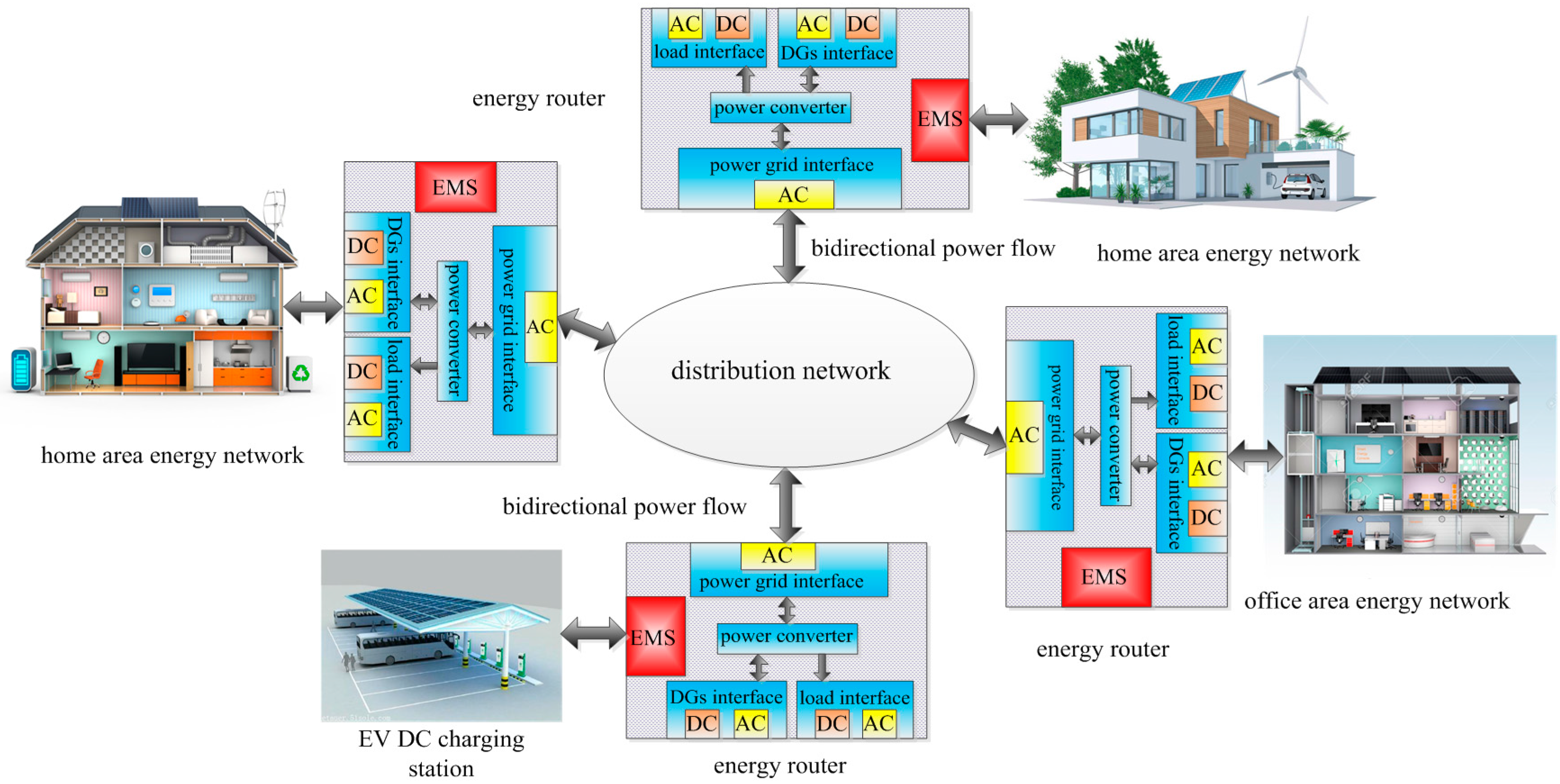
Figure 1 is the vision of the energy router-based HEMS in the future Energy Internet. The energy routers will serve as the “energy hub” between the energy subsystems (could be a house, an office or a charging station) and the distribution network, as well as the energy interfaces (both AC and DC) for all the DGs, energy storage system and loads within the home area energy network. The EMS of the energy router will schedule the energy prosumption within the home area energy network such that energy is distributed adequately among the loads, and redundant energy from the DGs could be stored by ESS or fed back into the distribution grid.
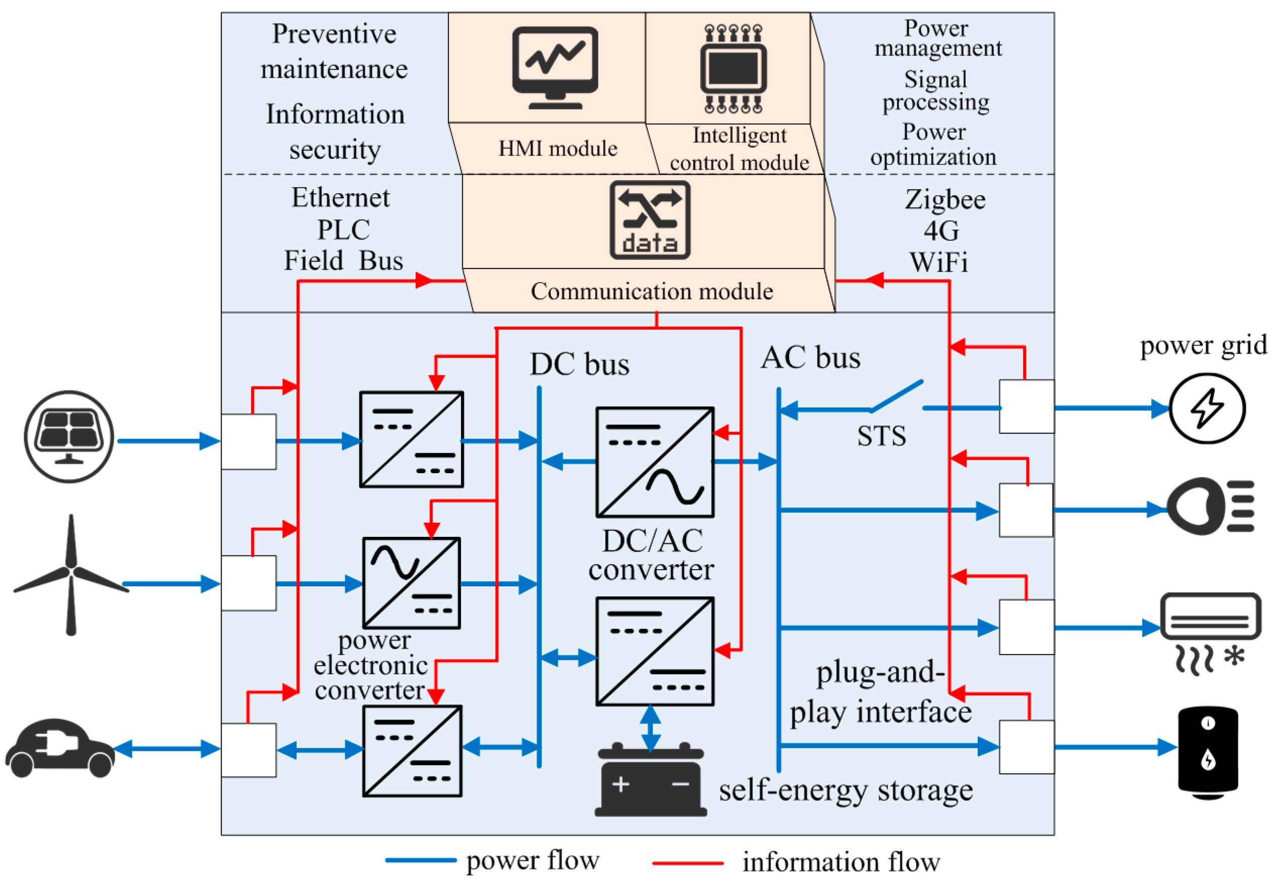
Figure 2 shows the configuration of the energy router-based HEMS in detail, which features high quality bidirectional power conversion, standardized plug-and-play power interfaces, as well as local operational information collections and effective energy management strategies. The energy router is mainly composed of the following components: (1) the power electronics converters, including the DC/AC converter for bidirectional power flow between the AC and DC buses, and the power converters for energy transfer between the power sources and the DC bus; (2) the plug-and-play interfaces for all the DGs, ESS and loads; (3) the self-energy storage system consists of battery, supercapaciter and their power converters, which serves as the “energy buffer” of the HEMS; (4) the Static Transfer Switch (STS) used for grid connection; and (5) the EMS which consists of the communication module, intelligent control module, and HMI module.
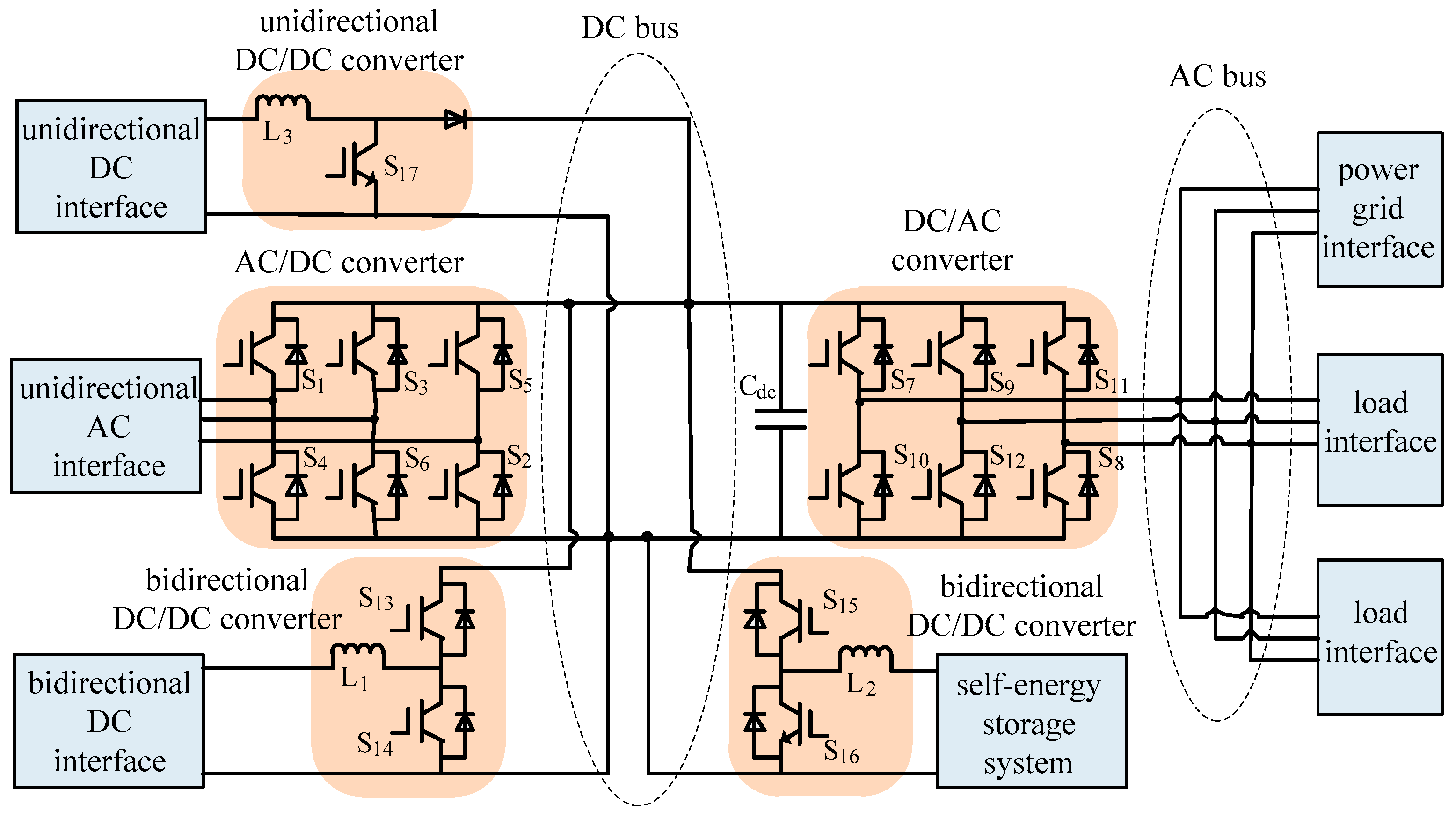
As shown in Figure 3, there are various topologies for the power electronic converters to accommodate different types of DGs and ESSs. A bidirectional DC/AC converter lies between the DC and AC buses. The plug-and-play power interfaces for DGs and loads can be classified into unidirectional AC or DC interfaces for the DGs and loads, and bidirectional DC interfaces for the EV and ESS. Power metering modules are embedded in the plug-and-play power interfaces to monitor the operation status and power quality of the DGs, and upload these measurements to the intelligent control module. Besides, protection functionalities are also provided by the plug-and-play interface in case faults or failures may occur.
Random and intermittent characteristics of the RESs will bring voltage fluctuations, frequency fluctuations and other power quality problems to the HEMS [13,29,30]. As the “energy buffer” within the energy router, the self-energy storage system can be used to maintain power balance for the whole system.
The communication module provides various information access interfaces and supports multiple communication protocols. Wired communications such as Ethernet, power line carrier (PLC) and RS485, and wireless communications such as Wi-Fi, 4G and ZigBee, can be utilized to collect operational data such as voltage, current and frequency from the DGs, ESS, loads, power lines and the converters in real time, and can also be used for information interaction among the intelligent control module, HMI module and other energy routers.
The intelligent control module is the “brain” of the energy router. It analyses the operational data collected from the DGs, ESS, loads, power lines and the converters, schedules the operation status of the converters such that energy is allocated adequately among the loads, and redundant energy from the DGs could be stored by ESS or fed back into the distribution grid.
The HMI module enables the user to learn about the operation status of the HEMS, and provides the functionality for the user to run the power management process manually. Preventive maintenance and operation parameter setting for the energy router can also be performed remotely through the HMI.
3. Coordinated Control Scheme for the Energy Router
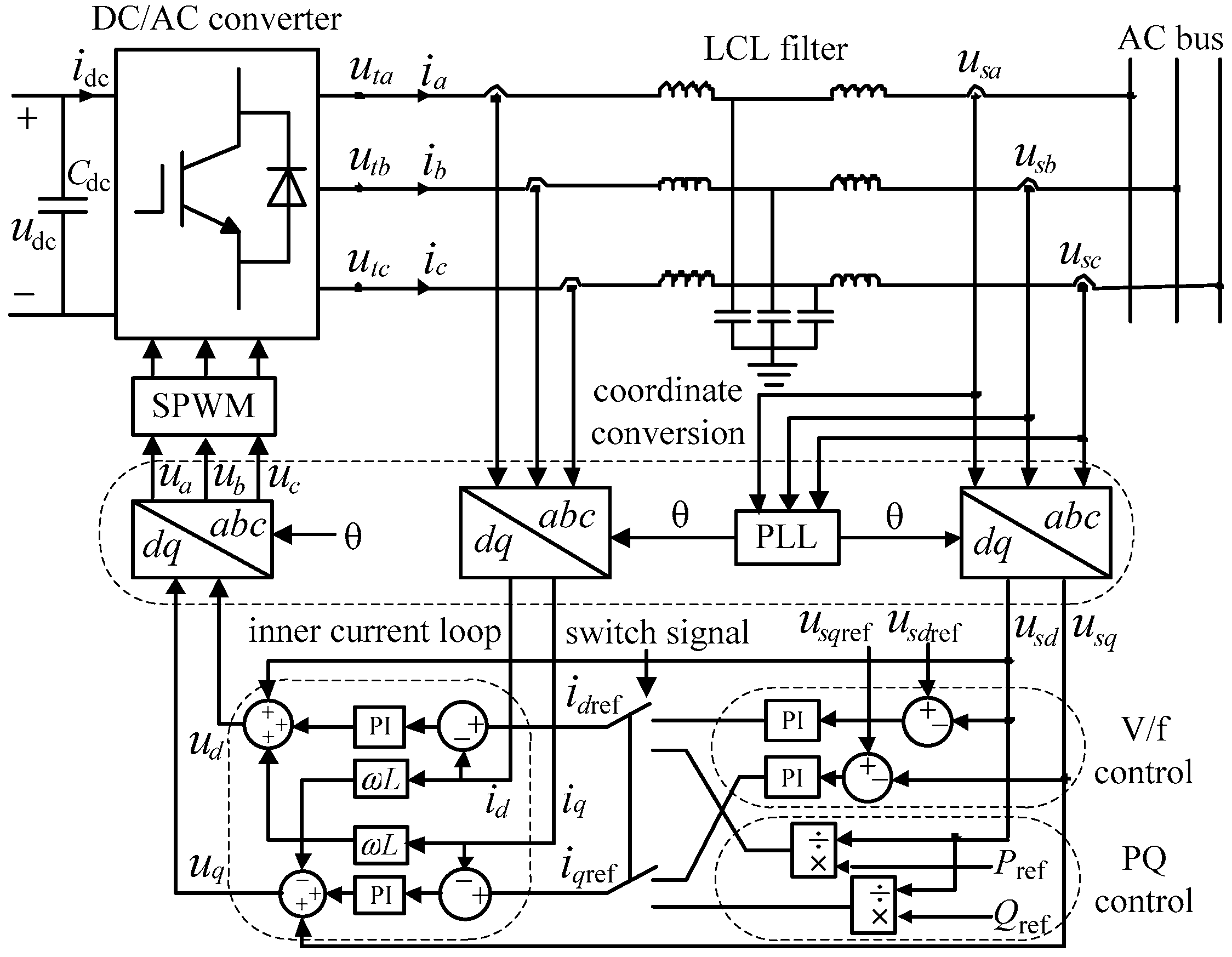
3.1. Control Methods of the DC/AC Converter
The energy router-based HEMS can operate in either grid-connected or isolated mode. In grid-connected mode, the voltage and frequency of the AC bus keep synchronous with the power grid, so the DC/AC converter (shall be referred as “main converter” in the rest of this paper) can achieve power balance by PQ control. In the dq rotation coordinate system, the power transferred to the AC side can be expressed as,
where usd and usq are the d axis and q axis components of the AC voltage us respectively, id and iq are the d axis and q axis components of the AC current iabc respectively. If the direction of d axis coincides with the sinusoidal vector of the power grid, the q axis component of the AC voltage will be zero. Then Equation (1) can be simplified as follows,
where Pref and Qref are the active and reactive reference power, respectively. Equation (2) indicates that active power and reactive power transferred to the AC side can be controlled through id and iq.
Since the capacitor branch in LCL filter is utilized to filter the harmonic current around the switching frequency, the effect of capacitor branch on fundamental components can be neglected. Aimed at the fundamental components, the output voltage of the main converter under dq rotation coordinate system can be derived through the following equation,
where L is the filter inductance. According to Equation (3), the inner current loop can be realized through PI regulators as Equation (4) shows,
The schematic of the PQ control module is shown in Figure 4.
As in isolated mode, the voltage and frequency of the AC bus will be stabilized under the V/f control of the main converter, which is also shown in Figure 4. The reference current in d and q axis of the V/f controller derived through PI regulators can be expressed as,
where usdref and usqref are the reference components of the AC voltage us in d axis and q axis.
The inner current loop can be used to restrain the influence of load disturbances and improve dynamic response of the AC system. It works based on the reference current value generated by V/f control and can also be expressed by Equation (4). Unlike PQ control, a virtual phase-locked loop is utilized by the V/f controller to acquire a constant frequency, and sinusoidal signal generated by the virtual phase-locked loop is taken as the reference vector. As stated above, the direction of d axis coincides with this vector, then usqref should be zero.
3.2. Reference Voltage and Current Compensation Strategy for Mode Switching of the Energy Router
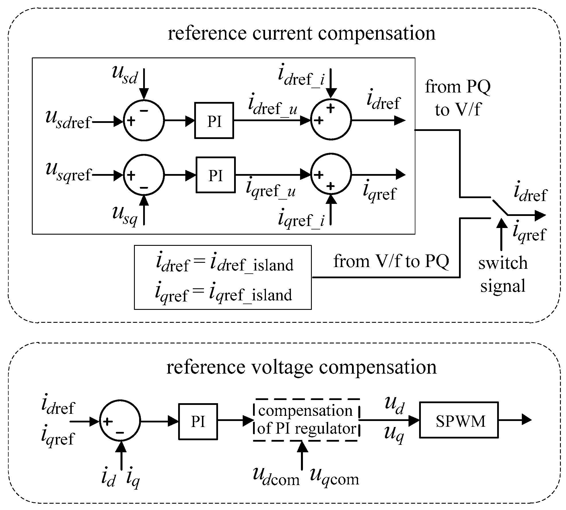
When the HEMS needs to switch between grid-connected mode and isolated mode, the main converter of the energy router must switch between PQ control and V/f control. Unlike the case of switching from grid-connected mode to isolated mode, the AC output of the energy router must be synchronized with the power grid to guarantee phase congruency during the switch from isolated mode to grid-connected mode [31]. In order to avoid huge transient impact and reduce the power fluctuation during the course of switching, a reference voltage and current compensation strategy shown in Figure 5 is implemented by the main converter during the transition process. The PQ control and V/f control will use the same inner current loop; only the mode of outer loop is switched [32].
3.2.1. Reference Voltage Compensation
It is assumed that ud_i and uq_i are the d axis and q axis voltage components generated by the PI regulators of the inner current loop before switching from PQ control to V/f control, while ud_u and uq_u are the d axis and q axis voltage components generated by PI regulators after switching. The PI regulator outputs are in steady state before the main converter switches from PQ control to V/f control. After switching, PI regulator will adjust its outputs from zero to new steady state gradually. This process requires a certain amount of time for adjustment. In order to avoid an abrupt change of the PI regulator outputs during the course of mode switching and realize smooth transition of the voltage modulation signal ud and uq, the compensation items are added into Equation (4) as shown in Equation (6),
It can also be utilized when the main converter switches from V/f control to PQ control. Equation (6) indicates that the PI regulator outputs before switching are added as compensation during the course of switching. When the main converter switches from PQ control to V/f control, ud_i and uq_i are used as the compensation items udcom and uqcom as shown in Figure 5. When the main converter switches from V/f control to PQ control, ud_u and uq_u are used as udcom and uqcom.
3.2.2. Reference Current Compensation
It is assumed that idref_i and iqref_i are the active and reactive output currents generated by PQ control before switching, idref_u and iqref_u are the active and reactive output currents generated by V/f control after switching. Since idref_u and iqref_u are adjusted to steady values from zero by PI regulators of V/f control gradually, there will be an abrupt change between the steady output currents before switching and the output currents after switching. The following reference current compensation equation is established to avoid this abrupt change,
Equation (7) indicates that output currents idref_i and iqref_i before switching are added to the reference currents as compensation during the course of switching.
In PQ control, sinusoidal signal of the power grid is taken as the reference vector and the direction of d axis coincides with it. In V/f control, sinusoidal signal generated by the virtual phase-locked loop is taken as the reference vector of the d axis direction. During the course of switching, the phase of the sinusoidal vector under PQ control is taken as initial phase of d axis direction. After switching, the phase of d axis direction will be gradually converging to the phase of sinusoidal vector generated by the virtual phase-locked loop under V/f control.
If the HEMS is in isolated mode for a long time, active and reactive output currents generated by V/f control will already be steady values. In this paper, idref_island and iqref_island are used to represent active and reactive output current of V/f control. The d axis and q axis components of the reference currents during the course of switching can be chosen as,
Equation (8) indicates that the steady active and reactive output currents before switching are used as actual reference currents during the course of switching. It is an effective solution to suppress transient impact and achieve smooth transition. After switching, idref and iqref will be gradually converging to a new steady state according to the actual active reference power Pref and reactive reference power Qref of the PQ control.
In order to ensure smooth transition of d axis direction, the phase of the sinusoidal vector under V/f control should to be taken as initial phase of d axis direction during the course of switching. After switching, the phase of d axis direction will gradually converge to the phase of sinusoidal vector of the power grid under PQ control.
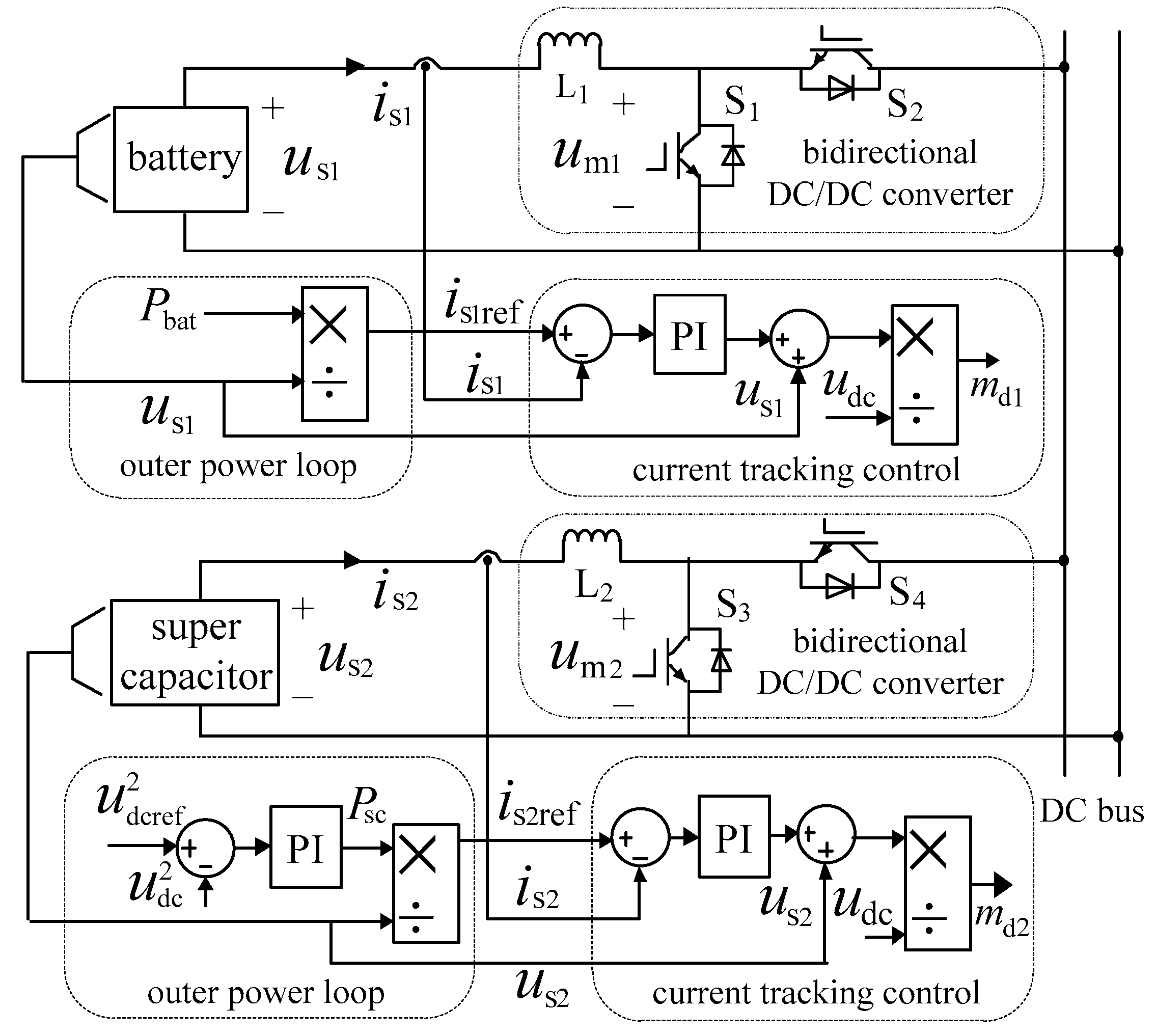
3.3. Power-Based Current Tracking Control for Self-Energy Storage System
The self-energy storage system consists of a battery unit and a supercapacitor, because the combination of their characteristics has complementary advantages for stabilizing the DC bus voltage [33]. As shown in Figure 3, the battery and supercapacitor are connected to the DC bus through bidirectional DC/DC converters.
Compared to the method to control charging or discharging currents directly, the indirect method works better to maintain the instantaneous power balance by controlling the charging or discharging power [34]. In order to maintain the system power balance, the following equation must be satisfied,
where Cdc is the capacitance of the DC bus capacitor, udc is the DC bus voltage, PDG is the output power of the DGs, Pbat and Psc are the charging or discharging power of the battery and the supercapacitor, and Pac is the active power fed to the AC bus through the main converter. Following equation is derived when the DC bus voltage is constant,
In view of the working characteristics of battery and supercapacitor, the battery is responsible for most of the charging or discharging power, while the supercapacitor is used to improve the transient characteristics of the DC bus voltage.
Current tracking control is used to regulate the charging or discharging currents of the battery and supercapacitor. The following equation describes the relationship between voltage and current of the battery or supercapacitor,
where is is the charging or discharging current, us is the output voltage, um is the modulation voltage of the DC/DC converter. On the basis of Equation (11), umref can be derived as,
Then modulation signals of the DC/DC converter are gotten,
Based upon above analysis, the control scheme of the charging or discharging process of the self-energy storage system is formulated. As shown in Figure 6, a power-based current tracking control method is adopted by the DC/DC converters to achieve instantaneous power balance in the energy router. The square of the error between the referenced voltage udcref and the actual voltage udc of the DC bus is used by PI regulator to derive the power Psc, which needs to be provided by supercapacitor. The power Pbat, which needs to be provided by the battery, will be calculated by the fuzzy logic controller described in the following section. The calculated charging or discharging power divided by output voltage is the reference current. Subsequently, the output currents of the battery and supercapacitor will track the reference currents is1ref and is2ref through the PI regulators. Then the modulation signals md1 and md2 can be derived to control the DC/DC converters of the battery and supercapacitor.
4. Power Management for the Energy Router
4.1. Design of the Fuzzy Logic Controller
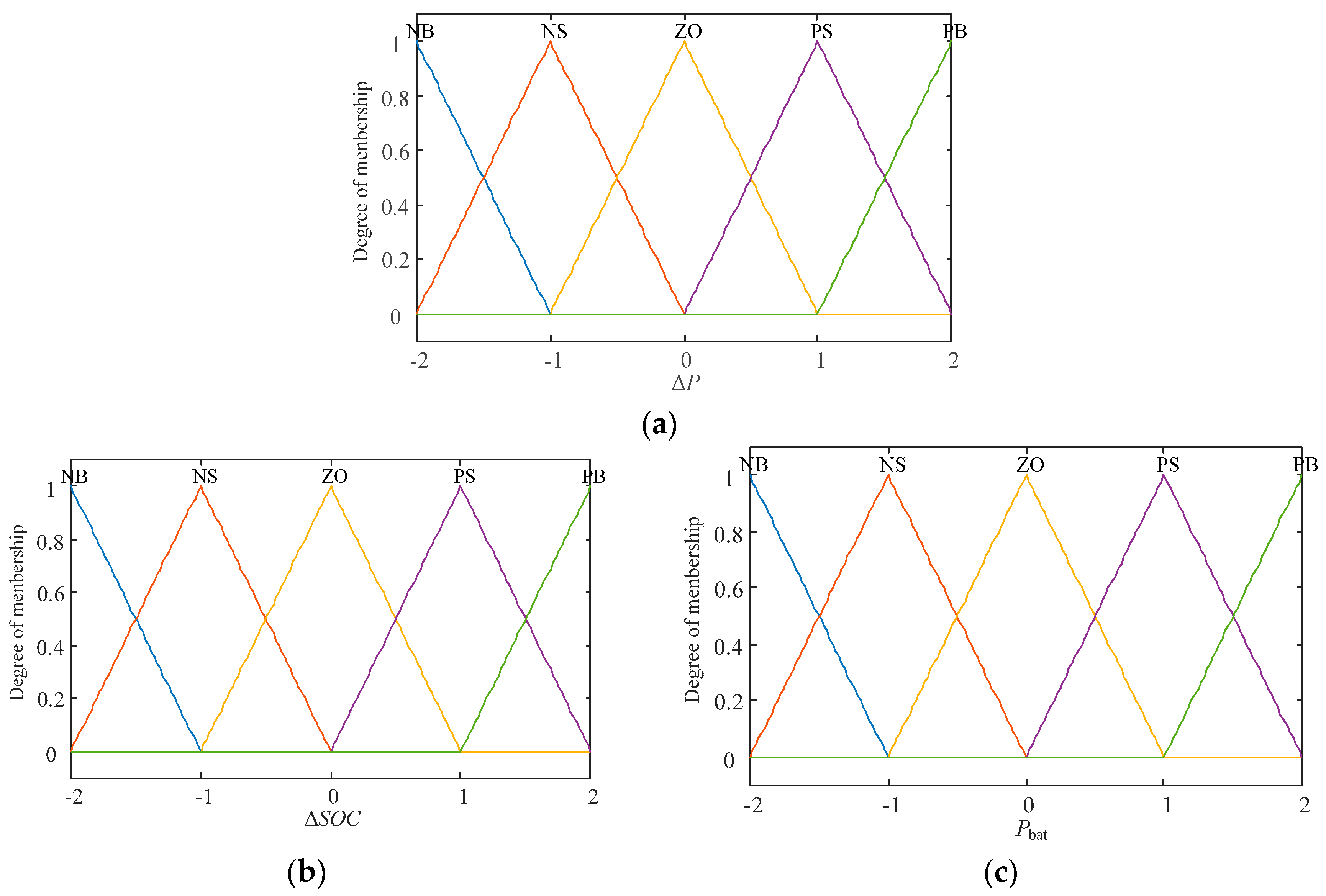
As the “energy buffer” of the HEMS, the self-energy storage system works to suppress the power fluctuation generated by the DGs when they get access to the HEMS through the energy router. Hence one of the key issues of the HEMS is to regulate the charging or discharging power of the battery in real time. On the one hand, the charging or discharging power is determined based on the gap between DG outputs and load demand; On the other hand, the SOC should also be considered to extend the service life of the battery unit. In order to maintain balance between these two aspects, the fuzzy logic controller [24] is designed to determine the charging and discharging power of the battery.
4.1.1. Fuzzification of the Controller Input and Output
Based on previous analysis, the fuzzy logic controller has a two-dimensional structure. The inputs of the controller can be derived by the following equations,
where SOCavr is the average value of the SOC. The charging or discharging power Pbat is chosen as the output of the controller. Table 1 shows the quantitative results of the input and output.
The basic domains of the input and output vary according to different design requirements. In this paper, SOCmax is set to 90% and SOCmin to 50%. The maximum charging or discharging power is set to 2.5 kW. Five linguistic states, NB (negative big), NS (negative small), ZO (zero), PS (positive small) and PB (positive big), are considered for the controller input and output. Based on the quantitative results, the triangular membership functions of the input and output are established as shown in Figure 7.
4.1.2. The Establishment of Fuzzy Logic Rules
After completing the design of membership functions, fuzzy logic rules should be established according to the basic experience [35].
The specific charging or discharging criterions of the battery are:
(1) When the DG output is lower than the load demand, i.e., ΔP < 0, and SOC is lower than SOCavr, i.e., ΔSOC < 0, which means SOC is closer to SOCmin than to SOCmax, the battery should work in shallow discharge state;
(2) When the DG output is lower than the load demand, i.e., ΔP < 0, and SOC is greater than SOCavr, i.e., ΔSOC > 0, which means SOC is closer to SOCmax than to SOCmin, the battery should work in deep discharge state;
(3) When the DG output is lower than the load demand, i.e., ΔP < 0, and SOC is equal to SOCavr, i.e., ΔSOC = 0, the battery can either work in shallow or deep discharge state according to the specific value of ΔP;
If ΔP is closer to −3.75 kW than to 0 kW, the battery should work in deep discharge state, otherwise the battery will work in shallow discharge state;
(4) When the DG output is greater than the load demand, i.e., ΔP > 0, and SOC is lower than SOCavr, i.e., ΔSOC < 0, the battery should work in deep charge state;
(5) When the DG output is greater than the load demand, i.e., ΔP > 0, and SOC is greater than SOCavr, i.e., ΔSOC > 0, the battery should work in shallow charge state.
(6) When the DG output is greater than the load demand, i.e., ΔP > 0, and SOC is equal to SOCavr, i.e., ΔSOC = 0, the battery can work in either shallow or deep charge state according to the specific value of ΔP.
If ΔP is closer to 3.75 kW than to 0 kW, the battery should work in deep charge state, otherwise the battery will work in shallow charge state.
(7) When the DG output is equal to the load demand, i.e., ΔP = 0, the battery does not need to charge or discharge no matter SOC is greater or lower than SOCavr.
Corresponding to above charging or discharging criterions, the fuzzy logic rules are designed as shown in Table 2.
Then the set value of the charging or discharging power of the battery can be obtained by the centroid method, which is a kind of defuzzification methods, as shown in Equation (16).
where μc(xi) is the membership function of Pbat, xi is the value in the fuzzy domain of Pbat.
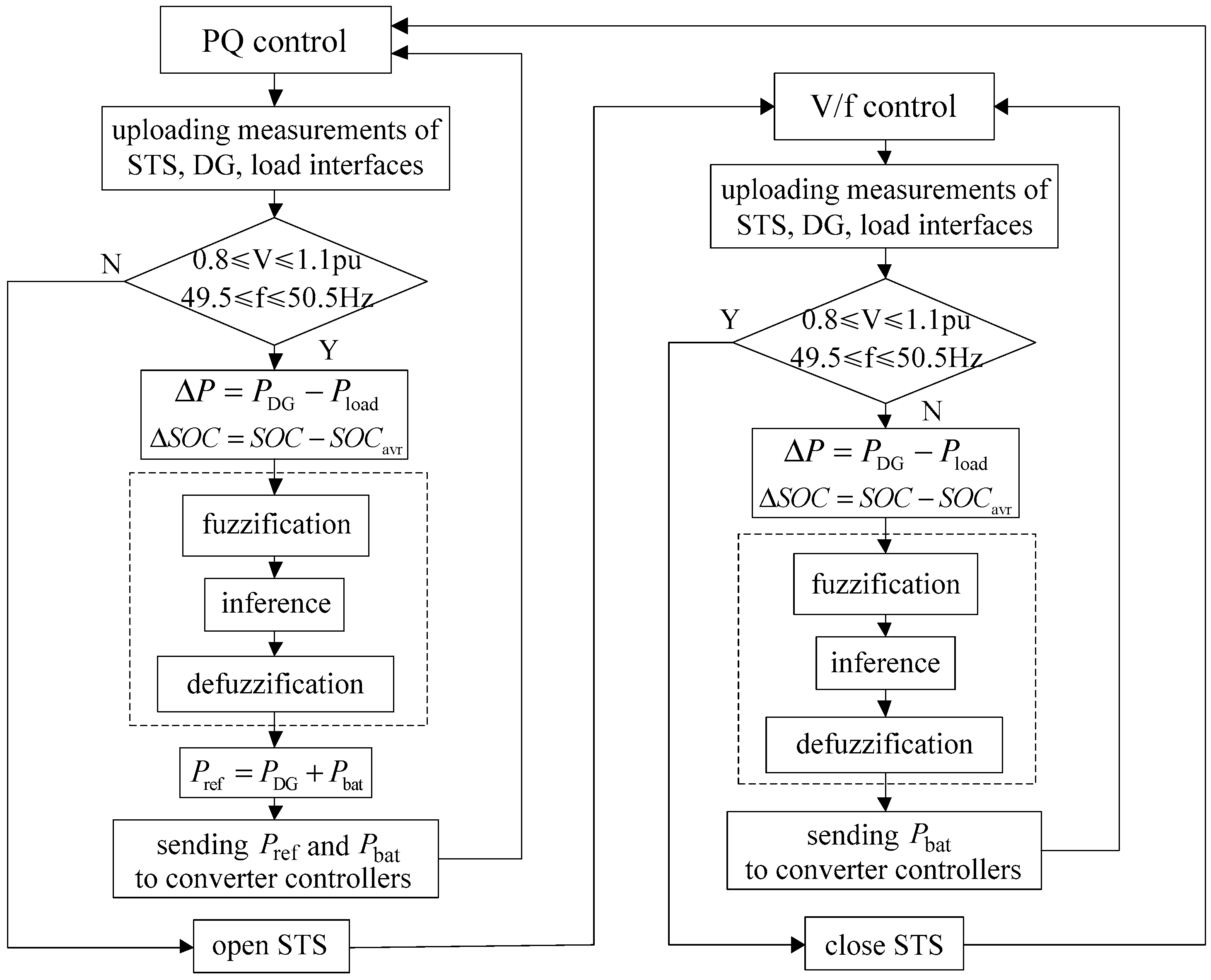
4.2. Power Management for the Energy Router
The process of power management for the energy router is formulated as shown in Figure 8. Comparing with the power management in isolated mode, the difference in grid-connected mode is the method to determinate active reference power of the PQ control. After getting the Pbat through the fuzzy logic controller, the sum of PDG and Pbat is chosen as the active reference power.
5. Case Study and Simulation Results
5.1. Simulation Parameters
The simulation model of the energy router-based HEMS is built on the MATLAB/Simulink platform. The DC bus voltage, AC bus phase-phase voltage and AC frequency are set to 750 V, 380 V and 50 Hz, respectively.
Photovoltaic (PV) cells are connected to DC bus through a boost circuit converter, which utilizes maximum power point tracking (MPPT) to make full use of the PV power. Incremental conductance algorithm is used for MPPT. The maximum output power of PV cells is 5 kW when the solar irradiance is 1000 W/m2 and the temperature is 25 °C.
It is assumed that the battery unit is used to undertake a load current of 80% at most and its continuous energy supply time t is 3 h. When the load demand is 5 kW, the rated load current Iload can be calculated according to the following equation,
where Urated is the AC bus voltage. Then battery capacity Cbat is calculated by the following equation,
where k = 0.4 is the average charging or discharging current coefficient, the value of γ is 50%. The calculated battery capacity is 22.8 Ah. Finally, the battery capacity is chosen to be 30 Ah, and its rated voltage is 50 V.
It is assumed that the supercapacitor can supply loads with rated power of 5 kW for 15 s when power of PV output is zero, and its safe voltage range is from 245 V to 375 V. Then the supercapacitor capacity Csc can be calculated by the following equation,
where Esc = 75 kJ, uscmax = 375 V and uscmin = 245 V, respectively. The supercapacitor capacity is chosen to be 2F.
Other main parameters are shown in Table 3.
5.2. Simulation Cases
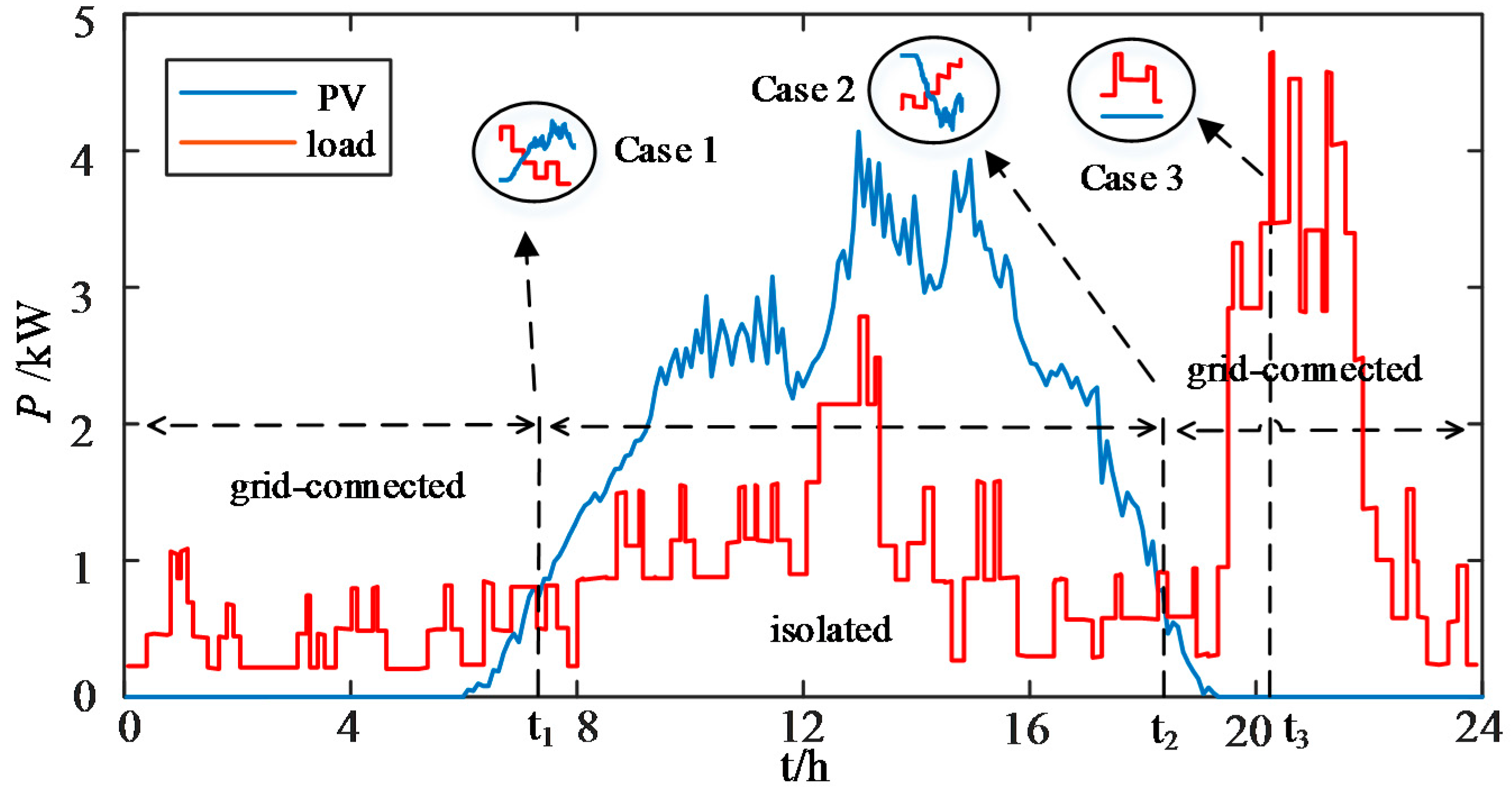
Figure 9 shows the daily measurements of PV generation and load consumptions of the energy router-based HEMS. The HEMS is in grid-connected mode and imports energy from the power grid during 0–t1 and t2–24, since the PV power generation is lower than load consumption. During the period between t1 and t2, the HEMS is in isolated mode. Because the HEMS will experience operation mode switch between grid-connected mode and isolated mode at the moment of t1 and t2, the operation of the HEMS at these moments will be investigated as study cases to verify the effectiveness and feasibility of the proposed control and management strategy for the energy router. The load power reaches the maximum point at t3, before which the power of PV output is already zero. Then the situation around the moment of t3 is chosen as another case to demonstrate the potential of the energy router-based HEMS in collaboration with the power grid to suppress the impact of load consumption fluctuations.
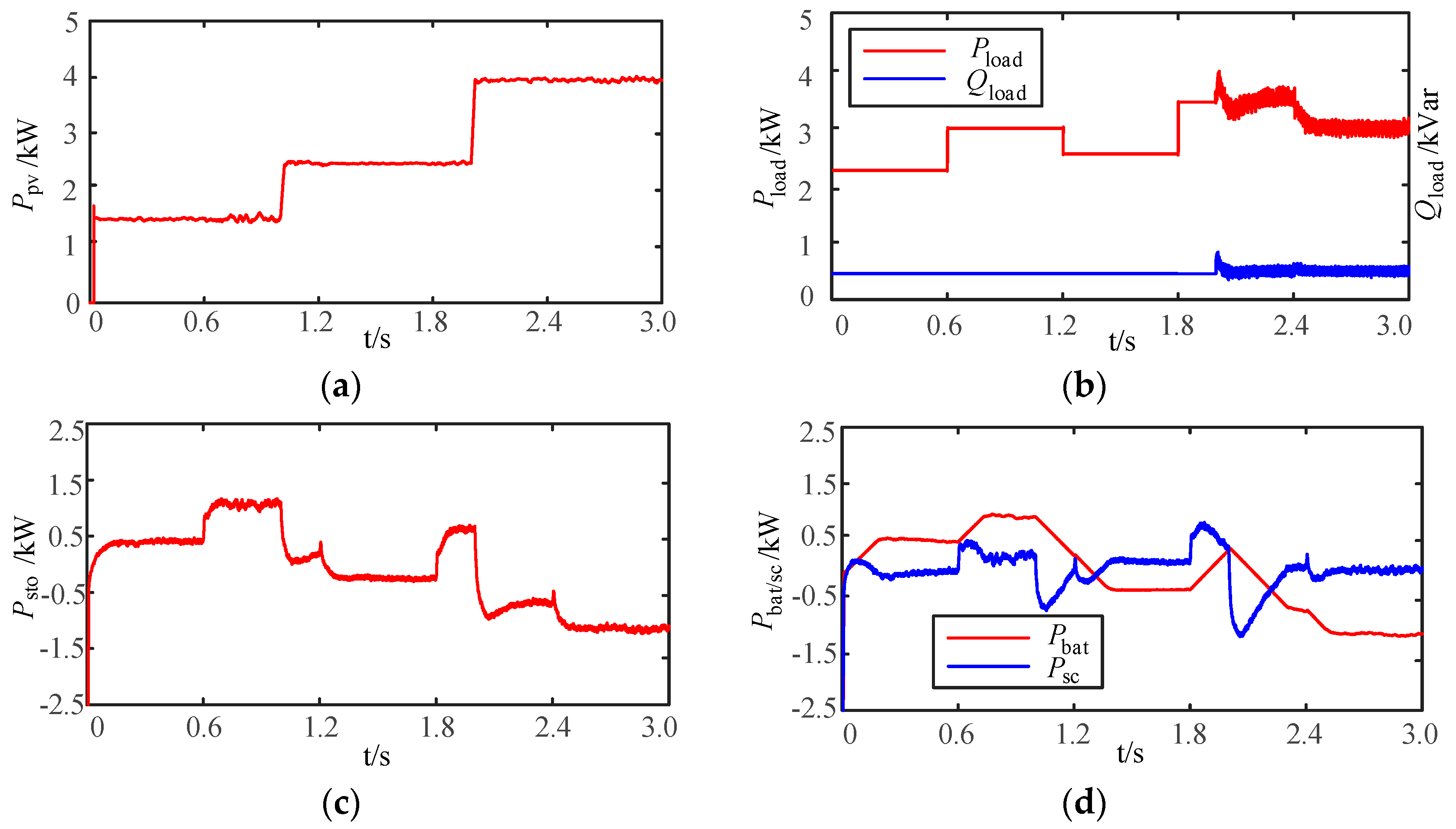
5.2.1. Case 1
Case 1 investigates the characteristics of the energy router-based HEMS in response to rapid increase of PV generation and transition from grid-connected mode to isolated mode. The variations of the PV output and load consumptions are shown in Figure 10a,b. As shown in Figure 9, solar irradiance varies rapidly around the moments of t1 and t2. As a consequence, PV output rises from 1.5 kW to 2.5 kW at 1.0 s, and then to 4 kW at 2.0 s. Meanwhile, the active load power changes from 2.25 kW to 3 kW at 0.6 s, to 2.5 kW at 1.2 s, to 3.5 kW at 1.8 s and 3 kW at 2.4 s, respectively. The reactive load power remains 0.5 kVar all the time. The HEMS switches from grid-connected mode to isolated mode at 2.0 s.
Figure 10c,d shows the operations of the self-energy storage system in case 1. According to the fuzzy logic rules, the charging or discharging power of the self-energy storage system is related to the difference between PV generation power and load consumption. Since PV generation power is lower than load consumption during 0–2.0 s, the self-energy storage system is discharging. However, as the discharging power cannot satisfy all the load demand, the power deficit is filled by energy input from the power grid. After that, the HEMS is in isolated mode and the self-energy storage system absorbs the excess power completely. According to the working characteristics of the battery and supercapacitor, the charging or discharging power of battery accounts for the majority of the energy surplus or deficit, while the supercapacitor mainly compensates for the drastic power fluctuations caused by abrupt changes of PV generation and load consumptions, since the battery cannot follow the quick variations of current supply.
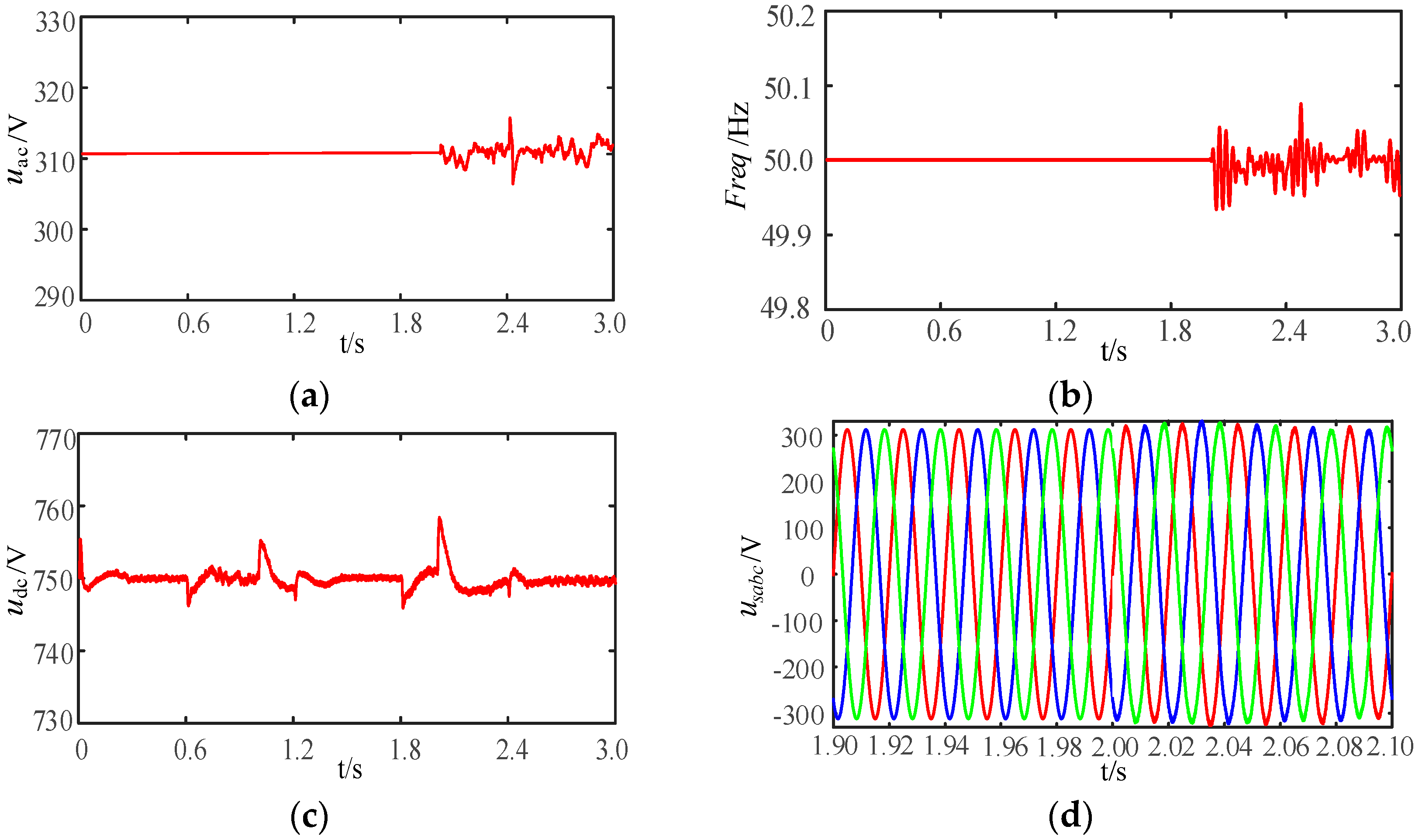
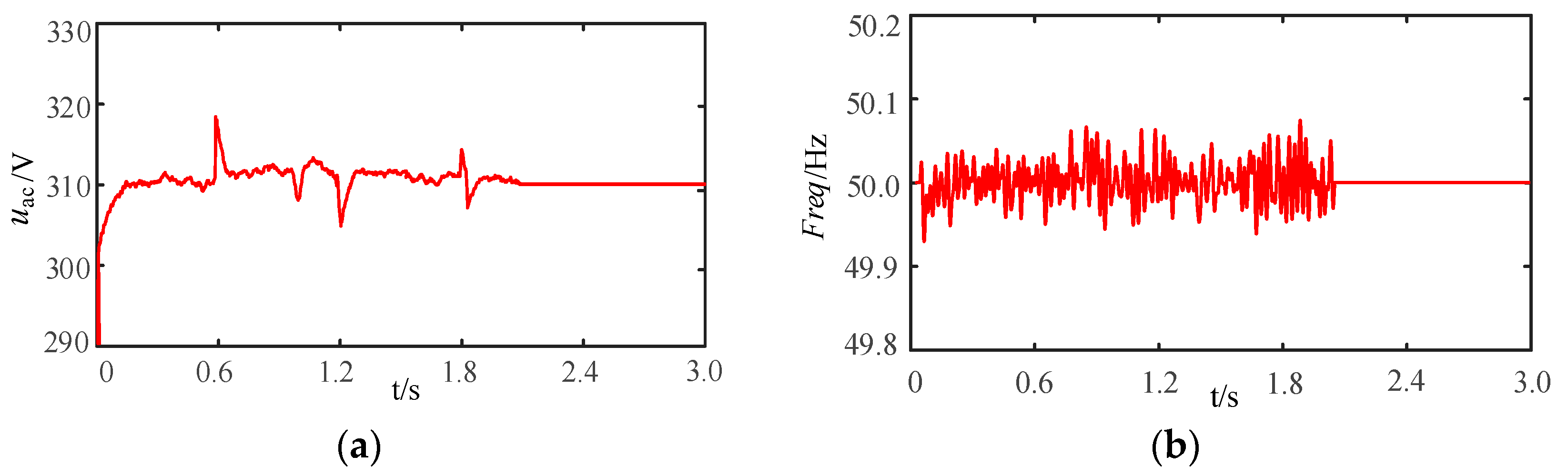
Figure 11a shows that the phase voltage amplitude of the AC bus remains constant before 2.0 s because the energy router is in connection with the power grid. When the energy router is in isolated mode during 2.0–3.0 s, there is slight fluctuation in the AC bus voltage, but is within dynamic balance under the V/f control. Similar to the AC bus voltage, there is little fluctuation in AC bus frequency, but is no more than ±0.1 Hz as shown in Figure 11b.
Figure 11c shows that DC bus voltage fluctuates at the moment of 0.6 s, 1.0 s, 1.2 s, 1.8 s, 2.0 s and 2.4 s when the energy router encounters instantaneous power imbalance caused by abrupt changes in PV output and load consumption, but restores stability in short time and remains constant during the rest of the time. As DC bus is the “energy pool” of the HEMS, these fluctuations are totally acceptable.
Figure 11d shows the three-phase voltage waveforms of the AC bus during the course of mode switching. The reference voltage and current compensation strategy ensures smooth transition at 2.0 s and there is no distortion on voltage waveforms. After 2.0 s, voltage amplitude isn’t 311 V seriously, which corresponds to the situation in Figure 11a.
5.2.2. Case 2
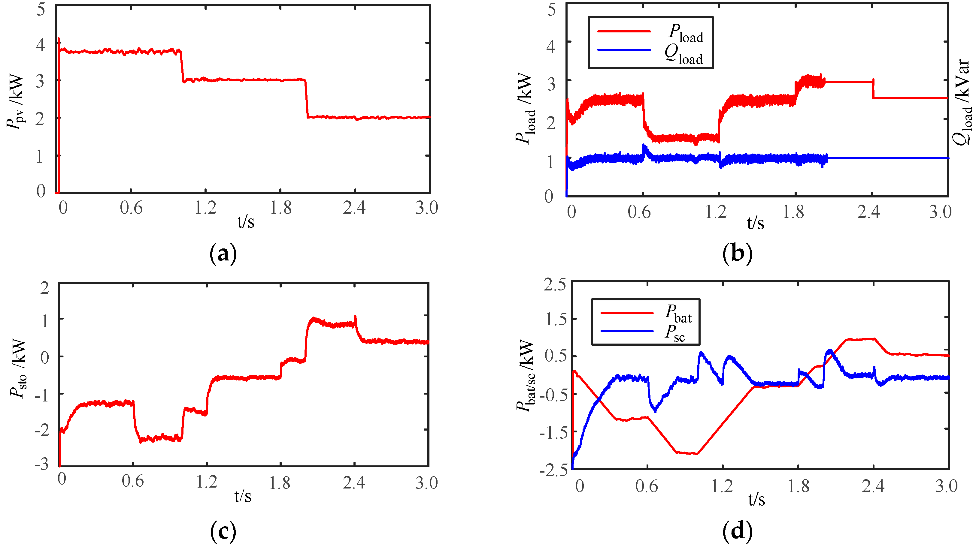
Case 2 investigates the characteristics of the energy router-based HEMS in response to rapid decrease of PV generation and transition from isolated mode to grid-connected mode. At the moment around t2, the solar irradiance decreases rapidly. As shown in Figure 12a,b, the PV output drops from 3.75 kW to 3.0 kW at 1.0 s, and then drops to 2.0 kW at 2.0 s. Meanwhile, the active load power is 1.5 kW during 0.6–1.2 s, 3 kW during 1.8–2.4 s and 2.5 kW during rest of the time. The reactive load power remains 1 kVar all the time. The HEMS switches to grid-connected mode from isolated mode at 2.0 s due to insufficient PV generation for load demand.
Figure 12c,d shows the operations of the self-energy storage system in case 2. As the energy buffer of the energy router, the self-energy storage system has played a critical role in suppressing the power fluctuations caused by operation mode switching and variations of PV generation and load consumptions, under the control of the fuzzy logic rules.
It is observed from Figure 13a that the AC bus phase voltage is in dynamic balance under the V/f control before 2.0 s. After that, the AC bus voltage is synchronized with the power grid voltage. The situation of the AC bus frequency is same as the AC bus voltage; fluctuations in frequency occur during isolated mode.
Similar to case 1, the DC bus voltage fluctuates at 0.6 s, 1.0 s, 1.2 s, 1.8 s, 2 s and 2.4 s due to transient imbalance caused by the instantaneous power fluctuations.
Unlike case 1, phase congruency between the energy router and power grid should be taken into consideration when the energy router switches from isolated mode to grid-connected mode in case 2. Figure 13d shows the voltage phase difference between the power grid and AC bus of the energy router. The phase difference around 2.0 s is no more than ±2°, which means the energy router can transfer to grid-connected mode from isolated mode smoothly.
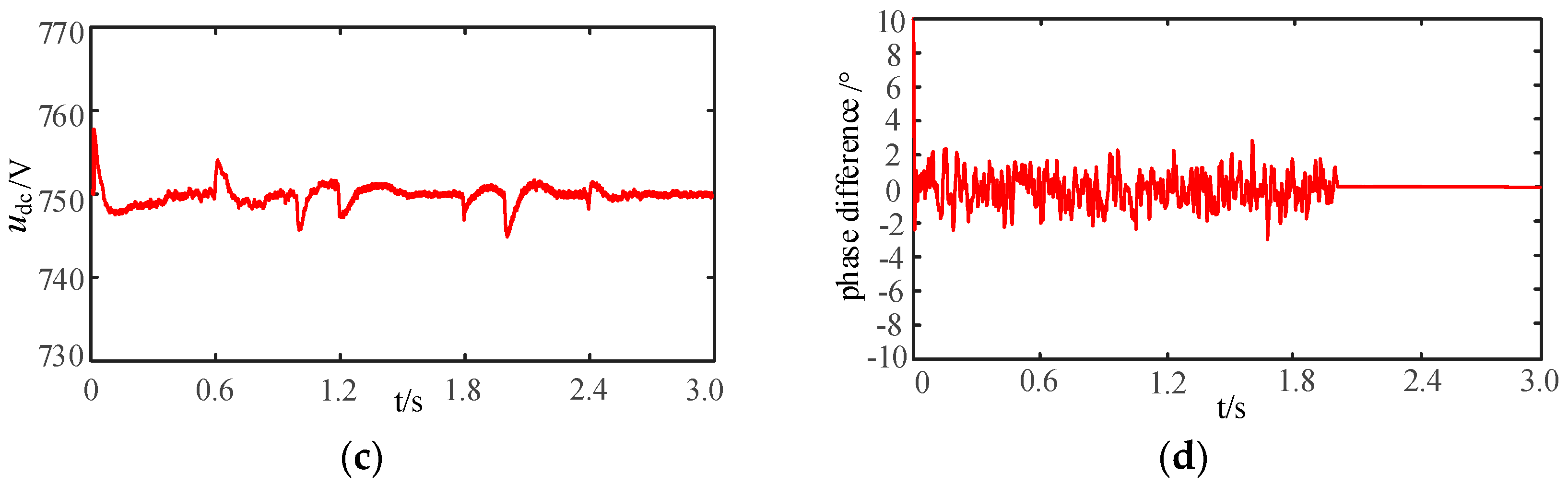
In order to illustrate the dynamic mode switching course of the energy router, the situations of the switching process with and without the compensation strategy are demonstrated in Figure 14a,b, respectively. As shown for the case with compensation in Figure 14a, three-phase voltage waveforms are continuous and there is no distortion or abrupt change at the moment of mode switching. The smooth transition of three-phase voltage is realized under the control of reference voltage and current compensation strategy.
Figure 14b shows the three-phase voltage waveforms without compensation strategy. During 2.00–2.04 s, the three-phase voltage waveforms are far from standard sinusoidal. Because both the reference currents and the inner loop PI regulator outputs have experienced an abrupt change during mode switching, the output three-phase voltage waveforms are distorted obviously, which may cause severe fault or even failure of the mode switching.
5.2.3. Case 3
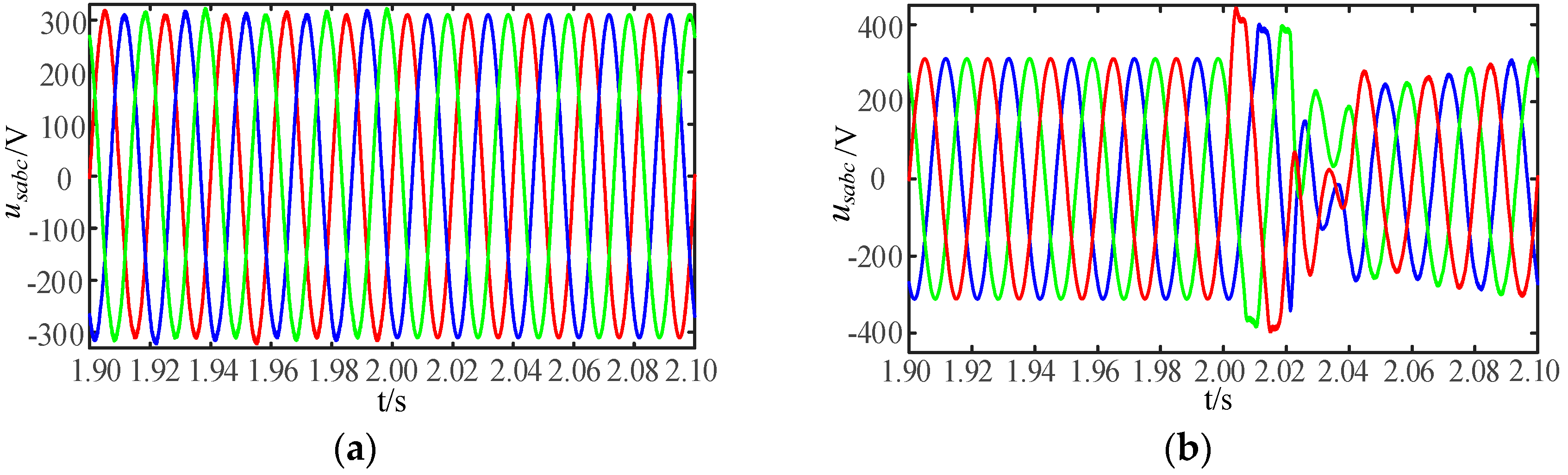
Case 3 investigates the characteristics of the energy router-based HEMS in response to drastic variations of load consumptions and its functionality to collaborate with the power grid in suppressing the impact of load consumption fluctuations. The active load power increases to the peak value during 1.0–2.0 s, which corresponds to the situation around t3 in Figure 9. The active load power decreases drastically at 2.0 s. The simulation results are demonstrated in Figure 15.
When the HEMS operates without the energy router, the PV power has to be fed into the power grid immediately when it is generated, then all the power for load consumptions will come from the grid. In that case, the power grid will suffer “double impacts” of RES power injections during daytime and peak loads in the evening, as shown in the profiles of measured daily PV generation and load consumptions in Figure 9.
Figure 15b demonstrates the profiles of active power imported from the distribution network to the HEMS at the peak load moment of t3. The two curves show the power injections under the situations with and without energy router, when the load demand varies drastically. When the HEMS operates with the energy router, the self-energy storage system is in charging state during day time when PV output exceeds the load demand. When load peak comes in the evening, as shown in case 3, most part of the load variation is “damped” by the self-energy storage system. Therefore, the profile of power imported from the grid is quite smooth, comparing with the situation without the energy router.
Figure 15d–f demonstrate the profiles of the DC bus voltage, AC bus voltage and frequency during the process of load variation. As the “energy pool” of the HEMS, the DC bus voltage fluctuates a little when the load demands change abruptly, while the AC bus voltage and frequency are smooth and not disturbed by the load variations during the whole process, owe thanks to the power compensation from the self-energy storage system. Although the energy router does not facilitate autonomous load shifting, the self-energy storage system has been successful in “energy shifting” by keeping surplus solar power stored during day time and feeding it back in support of the power grid during load peak time in the evening. The AC bus voltage and frequency maintain stable, which means the load variations within the HEMS does not have negative effects on the power grid since the HEMS is in connection with the grid at this moment. Therefore, we can conclude that if all the residential energy prosumers could handle the problem of RES generation and load variation like the presented energy router-based HEMS does, the peak load burden to the power grid would be alleviated considerably.
6. Conclusions
This paper focuses on the implementation of a low-voltage energy router-based HEMS for optimal use of RESs, while remaining “operational friendly and beneficial” to the power grid. The behaviors of the energy router-based HEMS in correlation with the power grid are investigated, and a coordinated control scheme for smart energy management is developed. The energy router is composed of internal DC and AC buses, multiple power electronics converters, a self-energy storage system and plug-and-play energy interfaces to multiple DGs, ESS and electric loads.
The control scheme consists of two parts: a reference voltage and current compensation strategy for the main converter of the energy router and a fuzzy logic control-based power management strategy for the self-energy storage system. The design of the control scheme is mainly concerned with two issues: (1) characteristics of the HEMS in response to rapid increase of RES generation, and transitions between the grid-connected mode and isolated mode; and (2) characteristics of the HEMS in response to drastic variations of load consumptions and its functionality to collaborate with the power grid in suppressing the impact of RES output fluctuations and load consumption variations.
The system model is built on the MATLAB/Simulink platform, and simulation results have shown that: (1) the presented reference voltage and current compensation strategy enables the energy router-based HEMS for smooth operation mode switching, which is essential for the HEMS to make full use of the RES generations; and (2) by precisely regulating the operation of the self-energy storage system, the presented fuzzy logic control-based power management strategy is remarkable for maintaining the instantaneous power balance within the energy router and suppressing the power fluctuation generated by the abrupt changes of the DG outputs and load consumptions.
The work of this paper have demonstrated that: (1) energy router is the perfect choice to serve as an intelligent and multi-functional energy interface for HMES in the future energy internet; and (2) the presented control scheme for the energy router is a strong performer in making full use of the RES generations for the HEMS while maintaining the operational stability of the whole system, as well as in collaboration with the power grid to suppress the impact of RES output fluctuations and load consumption variations. The work in this paper will present a paradigm of smart energy management for the HEMSs of the future Energy Internet.
Acknowledgments
This work is supported by the “Science and Technology Project Plan of the Ministry of Housing and Urban-Rural Development of the People’s Republic of China” (Project No.: 2016-K1-018).
Author Contributions
All the authors have contributed significantly. Yingshu Liu conceived and designed the model and corresponding control methods; Jun Li performed the simulation; Jun Li, Yao Wu and Feng Zhou analyzed the results; Yao Wu and Feng Zhou made all graphics; Yingshu Liu and Jun Li wrote and revised the paper.
Conflicts of Interest
The authors declare no conflict of interest.
References
- Huang, A.Q.; Crow, M.L.; Heydt, G.T.; Zheng, J.P.; Dale, S.J. The Future Renewable Electric Energy Delivery and Management (FREEDM) System: The Energy Internet. Proc. IEEE 2011, 99, 133–148. [Google Scholar] [CrossRef]
- Wang, K.; Yu, J.; Yu, Y.; Qian, Y.; Zeng, D.; Guo, S.; Xiang, Y.; Wu, J. A Survey on Energy Internet: Architecture, Approach, and Emerging Technologies. IEEE Syst. J. 2017, PP, 1–14. [Google Scholar] [CrossRef]
- Kordkheili, R.A.; Pourmousavi, S.A.; Savaghebi, M.; Guerrero, J.M.; Nehrir, M.H. Assessing the Potential of Plug-in Electric Vehicles in Active Distribution Networks. Energies 2016, 9, 34. [Google Scholar] [CrossRef]
- Martins, V.F.; Borges, C.L.T. Active Distribution Network Integrated Planning Incorporating Distributed Generation and Load Response Uncertainties. IEEE Trans. Power Syst. 2011, 26, 2164–2172. [Google Scholar] [CrossRef]
- Gill, S.; Kockar, I.; Ault, G.W. Dynamic Optimal Power Flow for Active Distribution Networks. IEEE Trans. Power Syst. 2014, 29, 121–131. [Google Scholar] [CrossRef] [Green Version]
- Kroposki, B.; Lasseter, R.; Ise, T.; Morozumi, S.; Papatlianassiou, S.; Hatziargyriou, N. Making Microgrids Work. IEEE Power Energy Mag. 2008, 6, 40–53. [Google Scholar] [CrossRef]
- Guerrero, J.M.; Vasquez, J.C.; Matas, J.; Vicuña, L.G.; Castilla, M. Hierarchical Control of Droop-Controlled AC and DC Microgrids—A General Approach Towards Standardization. IEEE Trans. Ind. Electron. 2011, 58, 158–172. [Google Scholar] [CrossRef]
- Olivares, D.E.; Sani, A.M.; Etemadi, A.H.; Canizares, C.A.; Iravani, R.; Kazerani, M.; Hajimiragha, A.H.; Bellmunt, O.G.; Saeedifard, M.; Behnke, R.P.; et al. Trends in Microgrid Control. IEEE Trans. Smart Grid 2014, 5, 1905–1919. [Google Scholar] [CrossRef]
- Erdinc, O.; Paterakis, N.G.; Pappi, I.N.; Bakirtzis, A.G.; Catalão, J.P.S. A New Perspective for Sizing of Distributed Generation and Energy Storage for Smart Households under Demand Response. Appl. Energy 2015, 143, 26–37. [Google Scholar] [CrossRef]
- Kahrobaee, S.; Rajabzadeh, A.; Soh, L.K.; Asgarpoor, S. A Multiagent Modeling and Investigation of Smart Homes with Power Generation, Storage, and Trading Features. IEEE Trans. Smart Grid 2013, 4, 659–668. [Google Scholar] [CrossRef]
- Han, D.M.; Lim, J.H. Design and Implementation of Smart Home Energy Management Systems Based on Zigbee. IEEE Trans. Consum. Electron. 2010, 56, 1417–1425. [Google Scholar] [CrossRef]
- Gungor, V.C.; Sahin, D.; Kocak, T.; Ergut, S.; Buccella, C.; Cecati, C.; Hancke, G.P. Smart Grid and Smart Homes: Key Players and Pilot Projects. IEEE Ind. Electron. Mag. 2012, 6, 18–34. [Google Scholar] [CrossRef]
- Bevrani, H.; Ghosh, A.; Ledwich, G. Renewable Energy Sources and Frequency Regulation: Survey and New Perspectives. IET Renew. Power Gen. 2010, 4, 438–457. [Google Scholar] [CrossRef]
- Teleke, S.; Baran, M.E.; Bhattacharya, S.; Huang, A.Q. Rule-Based Control of Battery Energy Storage for Dispatching Intermittent Renewable Sources. IEEE Trans. Sustain. Energy 2010, 1, 117–124. [Google Scholar] [CrossRef]
- Ozturk, Y.; Senthilkumar, D.; Kumar, S.; Lee, G. An Intelligent Home Energy Management System to Improve Demand Response. IEEE Trans. Smart Grid 2013, 4, 694–701. [Google Scholar] [CrossRef]
- Shafiee, Q.; Dragičević, T.; Vasquez, J.C.; Guerrero, J.M. Hierarchical Control for Multiple DC-microgrids Clusters. IEEE Trans. Energy Convers. 2014, 29, 922–933. [Google Scholar] [CrossRef]
- Ahmed, M.S.; Mohamed, A.; Homod, R.Z.; Shareef, H. Hybrid LSA-ANN Based Home Energy Management Scheduling Controller for Residential Demand Response Strategy. Energies 2016, 9, 716. [Google Scholar] [CrossRef]
- Paterakis, N.G.; Erdinç, O.; Pappi, I.N.; Bakirtzis, A.G.; Catalão, J.P.S. Coordinated Operation of a Neighborhood of Smart Households Comprising Electric Vehicles, Energy Storage and Distributed Generation. IEEE Trans. Smart Grid 2016, 7, 2736–2747. [Google Scholar] [CrossRef]
- Pedrasa, M.A.A.; Spooner, T.D.; MacGill, I.F. Coordinated Scheduling of Residential Distributed Energy Resources to Optimize Smart Home Energy Services. IEEE Trans. Smart Grid 2010, 1, 134–143. [Google Scholar] [CrossRef]
- Byun, J.; Jeon, B.; Noh, J.; Kim, Y.; Park, S. An Intelligent Self-Adjusting Sensor for Smart Home Services based on ZigBee Communications. IEEE Trans. Consum. Electron. 2012, 58, 794–802. [Google Scholar] [CrossRef]
- Adinolfi, G.; Graditi, G.; Siano, P.; Piccolo, A. Multiobjective Optimal Design of Photovoltaic Synchronous Boost Converters Assessing Efficiency, Reliability, and Cost Savings. IEEE Trans. Ind. Inform. 2015, 11, 1038–1048. [Google Scholar] [CrossRef]
- Rodrigues, E.M.G.; Godina, R.; Shafie-khah, M.; Catalão, J.P.S. Experimental Results on a Wireless Wattmeter Device for the Integration in Home Energy Management Systems. Energies 2017, 10, 398. [Google Scholar] [CrossRef]
- Hong, Y.Y.; Lin, J.K.; Wu, C.P.; Chuang, C.C. Multi-Objective Air-Conditioning Control Considering Fuzzy Parameters Using Immune Clonal Selection Programming. IEEE Trans. Smart Grid 2012, 3, 1603–1610. [Google Scholar] [CrossRef]
- Chen, Y.K.; Wu, Y.C.; Song, C.C.; Chen, Y.S. Design and Implementation of Energy Management System with Fuzzy Control for DC Microgrid Systems. IEEE Trans. Power Electron. 2013, 28, 1563–1570. [Google Scholar] [CrossRef]
- Nguyen, P.H.; Kling, W.L.; Ribeiro, P.F. Smart Power Router: A Flexible Agent-Based Converter Interface in Active Distribution Networks. IEEE Trans. Smart Grid 2011, 2, 487–495. [Google Scholar] [CrossRef]
- Takahashi, R.; Tashiro, K.; Hikihara, T. Router for Power Packet Distribution Network: Design and Experimental Verification. IEEE Trans. Smart Grid 2015, 6, 618–626. [Google Scholar] [CrossRef] [Green Version]
- Behl, M.; Aneja, M.; Jain, H.; Mangharam, R. EnRoute: An Energy Router for Energy-Efficient Buildings. In Proceedings of the 10th International Conference on Information Processing in Sensor Networks (IPSN), Chicago, IL, USA, 12–14 April 2011. [Google Scholar]
- Stalling, B.P.; Clemmer, T.; Mantooth, H.A.; Motte, R.; Xu, H.; Price, T.; Dougal, R. Design and Evaluation of A Universal Power Router for Residential Applications. In Proceedings of the IEEE Energy Conversion Congress and Exposition (ECCE), Raleigh, NC, USA, 15–20 September 2012. [Google Scholar]
- Mahmud, M.A.; Hossain, M.J.; Pota, H.R. Voltage Variation on Distribution Networks with Distributed Generation: Worst Case Scenario. IEEE Syst. J. 2014, 8, 1096–1103. [Google Scholar] [CrossRef]
- Abapour, S.; Zare, K.; Mohammadi-ivatloo, B. Evaluation of Technical Risks in Distribution Network Along with Distributed Generation Based on Active Management. IET Gener. Transm. Distrib. 2014, 8, 609–618. [Google Scholar] [CrossRef]
- Micallef, A.; Apap, M.; Spiteri-Staines, C.; Guerrero, J.M. Single-Phase Microgrid with Seamless Transition Capabilities between Modes of Operation. IEEE Trans. Smart Grid 2015, 6, 2736–2745. [Google Scholar] [CrossRef]
- Wang, C. Analysis and Simulation Theory of Microgrids, 1st ed.; Science Press: Beijing, China, 2013; pp. 153–154. [Google Scholar]
- Kollimalla, S.K.; Mishra, M.K.; Narasamma, N.L. Design and Analysis of Novel Control Strategy for Battery and Supercapacitor Storage System. IEEE Trans. Sustain. Energy 2014, 5, 1137–1144. [Google Scholar] [CrossRef]
- Tian, H.; Li, X.; Chen, T.; Tan, S. Comprehensive Control Strategy of Hybrid Energy Storage based Photovoltaic Island Microgrid. Power Syst. Prot. Control. 2014, 42, 122–128. [Google Scholar] [CrossRef]
- Hasanien, H.M.; Matar, M. A Fuzzy Logic Controller for Autonomous Operation of a Voltage Source Converter-Based Distributed Generation System. IEEE Trans. Smart Grid 2015, 6, 158–165. [Google Scholar] [CrossRef]
Figure 1.
Architecture of the energy router-based HEMS.

Figure 2.
Configuration of energy router-based HEMS.

Figure 3.
Power electronic converters in the energy router.

Figure 4.
Control schematic of the DC/AC converter.

Figure 5.
The compensation strategy for the main DC/AC converter.

Figure 6.
Charging and discharging control of the self-energy storage system.

Figure 7.
Membership functions of the input and output: (a) Membership function of ΔP; (b) Membership function of ΔSOC; (c) Membership function of Pbat.
Figure 7.
Membership functions of the input and output: (a) Membership function of ΔP; (b) Membership function of ΔSOC; (c) Membership function of Pbat.

Figure 8.
Flow chart of power management.

Figure 9.
PV generation power and load power curves of energy router in a day.

Figure 10.
Simulation results of energy router in case 1: (a) PV generation; (b) Load consumptions; (c) Total charging or discharging power of the self-energy storage system; (d) Charging or discharging power of the battery and supercapacitor.
Figure 10.
Simulation results of energy router in case 1: (a) PV generation; (b) Load consumptions; (c) Total charging or discharging power of the self-energy storage system; (d) Charging or discharging power of the battery and supercapacitor.

Figure 11.
Parameter characteristics of energy router in case 1: (a) AC bus phase voltage amplitude; (b) AC bus frequency; (c) DC bus voltage; (d) Three-phase voltage waveforms of AC bus around the moment of mode switching.
Figure 11.
Parameter characteristics of energy router in case 1: (a) AC bus phase voltage amplitude; (b) AC bus frequency; (c) DC bus voltage; (d) Three-phase voltage waveforms of AC bus around the moment of mode switching.

Figure 12.
Simulation results of energy router in case 2: (a) PV generation; (b) Load consumptions; (c) Total charging or discharging power of the self-energy storage system; (d) Charging or discharging power of the battery and supercapacitor.
Figure 12.
Simulation results of energy router in case 2: (a) PV generation; (b) Load consumptions; (c) Total charging or discharging power of the self-energy storage system; (d) Charging or discharging power of the battery and supercapacitor.

Figure 13.
Parameter characteristics of the energy router in case 2: (a) AC bus phase voltage amplitude; (b) AC bus frequency; (c) DC bus voltage; (d) Voltage phase difference between energy router and power grid.
Figure 13.
Parameter characteristics of the energy router in case 2: (a) AC bus phase voltage amplitude; (b) AC bus frequency; (c) DC bus voltage; (d) Voltage phase difference between energy router and power grid.


Figure 14.
Mode switching results of the energy router: (a) Three-phase voltage waveforms of AC bus with compensation strategy; (b) Three-phase voltage waveforms of AC bus without compensation strategy.
Figure 14.
Mode switching results of the energy router: (a) Three-phase voltage waveforms of AC bus with compensation strategy; (b) Three-phase voltage waveforms of AC bus without compensation strategy.

Figure 15.
Simulation results of energy router in case 3: (a) Load consumptions; (b) The active power imported from the distribution network with or without energy router; (c) Total charging or discharging power of the self-energy storage system; (d) DC bus voltage; (e) AC bus phase voltage; (f) AC bus frequency.


Table 1.
Quantitative results of the input and output.
| Basic Domain | Fuzzy Domain | Quantization Factor | Fuzzy Subset | |
|---|---|---|---|---|
| ΔP | [−3.75 kW, 3.75 kW] | {−2, −1, 0, 1, 2} | 2/3.75 | [NB, NS, ZO, PS, PB] |
| ΔSOC | [−20%, 20%] | {−2, −1, 0, 1, 2} | 2/20 | [NB, NS, ZO, PS, PB] |
| Pbat | [−2.5 kW, 2.5 kW] | {−2, −1, 0, 1, 2} | 2.5/2 | [NB, NS, ZO, PS, PB] |
Table 2.
Fuzzy logic rule base.
| Pbat | ΔSOC | |||||
|---|---|---|---|---|---|---|
| NB | NS | ZO | PS | PB | ||
| ΔP | NB | PS | PS | PB | PB | PB |
| NS | PS | PS | PS | PB | PB | |
| ZO | ZO | ZO | ZO | ZO | ZO | |
| PS | NB | NB | NS | NS | NS | |
| PB | NB | NB | NB | NS | NS | |
Table 3.
Simulation parameters of energy router.
| Parameters | Value | Parameters | Value |
|---|---|---|---|
| LCL filter at the AC side of the DC/AC converter | 0.25 mH 250 μF 0.12 mH | PI of inner current loop in Figure 4 and Figure 5 | 0.15/1.15 0.15/1.15 |
| Inductances in DC/DC converters of self-energy storage system | 8 mH 8 mH | PI of V/f control in Figure 4 and Figure 5 | 0.05/40 0.05/40 |
| Inductance and capacitance in DC/DC converter of PV cells | 5.5 mH 68 μF | PI of current tracking control for battery in Figure 6 | 4/10 |
| Capacitance link to the DC bus | 120 μF | PI of current tracking control for supercapacitor in Figure 6 | 3/100 |
| Switching frequency of DC/DC converters of self-energy storage system | 2 kHz | PI of outer power loop in Figure 6 | 1/80 |
| Switching frequency of DC/DC converter of PV cells | 2 kHz | Switching frequency of DC/AC converter | 4 kHz |
© 2017 by the authors. Licensee MDPI, Basel, Switzerland. This article is an open access article distributed under the terms and conditions of the Creative Commons Attribution (CC BY) license (http://creativecommons.org/licenses/by/4.0/).
Share and Cite
MDPI and ACS Style
Liu, Y.; Li, J.; Wu, Y.; Zhou, F. Coordinated Control of the Energy Router-Based Smart Home Energy Management System. Appl. Sci. 2017, 7, 943. https://0-doi-org.brum.beds.ac.uk/10.3390/app7090943
AMA Style
Liu Y, Li J, Wu Y, Zhou F. Coordinated Control of the Energy Router-Based Smart Home Energy Management System. Applied Sciences. 2017; 7(9):943. https://0-doi-org.brum.beds.ac.uk/10.3390/app7090943
Chicago/Turabian StyleLiu, Yingshu, Jun Li, Yao Wu, and Feng Zhou. 2017. "Coordinated Control of the Energy Router-Based Smart Home Energy Management System" Applied Sciences 7, no. 9: 943. https://0-doi-org.brum.beds.ac.uk/10.3390/app7090943
Note that from the first issue of 2016, this journal uses article numbers instead of page numbers. See further details here.