Article

Study on the High Temperature Interfacial Stability of Ti/Mo/Yb0.3Co4Sb12 Thermoelectric Joints

State Key Laboratory of High Performance Ceramics and Superfine Microstructure, Shanghai Institute of Ceramics, Chinese Academy of Sciences, 1295 Dingxi Road, Shanghai 200050, China
*
Author to whom correspondence should be addressed.
Submission received: 31 August 2017 / Revised: 12 September 2017 / Accepted: 13 September 2017 / Published: 15 September 2017

Abstract

:
To improve the interfacial stability at high temperatures, n-type skutterudite (SKD) thermoelectric joints with sandwich structures of Ti/Mo/Yb0.3Co4Sb12 were successfully designed and fabricated. In this structure, Mo and Ti were introduced as the barrier layer with the goal of suppressing the interfacial diffusion and the buffer layer with the goal of enhancing the bonding strength, respectively. To evaluate the high temperature interfacial behavior of the Ti/Mo/Yb0.3Co4Sb12 joints, thermal shocking between 0 °C and 600 °C and isothermal aging at a temperature range of 550 °C to 650 °C were carried out in vacuum. During the isothermal aging process, Ti penetrates across the Mo layer, and finally diffuses into the Yb0.3Co4Sb12 matrix. By increasing the isothermal aging time, Ti continuously diffuses and reacts with the elements of Sb and Co in the matrix, consequently forming the multilayer-structured intermetallic compounds of Ti3Sb/Ti2Sb/TiCoSb. Diffusion kinetics was investigated and it was found that the interfacial evolution of the Ti/Mo/Yb0.3Co4Sb12 joints was a diffusion-controlling process. During the diffusion process, the formed Mo-Ti buffer layer acts as a damper, which greatly decelerates the diffusion of Ti towards the Yb0.3Co4Sb12 matrix at high temperatures. Meanwhile, it was found that the increase in the contact resistivity of the joints mainly derives from the inter-diffusion between Ti and Yb0.3Co4Sb12. As a result, the Ti/Mo/Yb0.3Co4Sb12 joint demonstrates the excellent stability of the interfacial contact resistivity. Service life prediction was made based on the stability of the contact resistivity, and it was found that the Ti/Mo/Yb0.3Co4Sb12 joint is qualified for practical applications at 550 °C.

Graphical Abstract

1. Introduction

Unlike traditional power generation systems, a thermoelectric power generator (TEG) produces electrical power based on the Seebeck effect, via the movement of charge carriers within thermoelectric materials under a temperature difference. Using the heat from radioisotopes, TEGs can supply electrical power for tens of years, and are now the only choice of power source for deep space explorers which fly far from the sun and therefore can no longer obtain sufficient sunlight energy [1,2]. In the past decade, TEGs have been regarded as one of the most promising candidates to recover waste heat from industries or automobiles and turn them into electricity [3,4], which can benefit from the remission of the fossil energy shortage and global warming. Recently, TEGs have become one of the research focuses, and are expected to act as power suppliers of wearable electronic equipment [5].
Intrinsically, the performance of a TEG depends on the property of the thermoelectric (TE) material, which is referred to as the dimensionless figure of merit of ZT. Among the investigated various systems of TE materials, silicides [6,7,8,9], half-heuslers [10,11], and tellurides (e.g., of Bi [12,13,14], Pb [15,16,17,18] and Ge [19,20]) have been widely studied and some have been practically applied in TEGs. Besides, a number of materials featuring excellent TE properties (high ZT value) and a relatively lower cost, low toxicity, and good mechanical properties, such as filled skutterudite (SKD), also attract extensive attention and have been actively pursued for being converted into TEGs [21,22,23,24,25,26].
Thermoelectric joints, consisting of TE materials and electrodes, are the fundamental parts and also the key components of a TEG. In practical applications, the performance of a TEG not only depends on the property of TE materials, but also depends on the temperature difference between the hot- and cold-sides of the TE material bulks. Higher hot-side temperatures usually lead to a larger temperature difference, further enhancing the performance of the TEG. Meanwhile, a higher hot-side temperature also encourages interfacial diffusion and accelerates the degradation of the contact property, especially the contact (electrical) resistivity, which definitely deteriorates the performance and stability of the TEGs.
Practically, the high temperature TEGs are expected to perform stably for a couple of years or even longer. For example, to make full use of the TE property, the hot side temperature of the CoSb3-based SKD joints should be 500 °C or higher. At such a high temperature, the major component in the SKD material, antimony, will react fiercely with most electrode materials (Cu, Ni, and Al, etc.) and then form single- or multi-layer interfacial intermetallics (IMC). The performance and stability of the TE joints are sensitively influenced by the microstructure and properties of the interface between the TE materials and electrode. To improve the interfacial stability of the SKD joints, a diffusion barrier layer is usually inserted between the electrode and the SKD material. Fan et al. firstly reported using Ti as the barrier layer in the CoSb3 [27]. Zhao et al. systematically studied the diffusion kinetics of the Ti/CoSb3 interface at high temperatures and predicted a service life of over 20 years for Ti/CoSb3 joints at 500 °C, using interfacial shearing strength as the criteria [28,29]. In Zhao’s work, when the working temperature increased to 550 °C, the diffusion speed at the Ti/CoSb3 interface increased by one order and the predicted service life dropped to within one year [28]. In 2014, similar interfacial evolution in Ti/Yb0.6Co4Sb12 joints was found and the method was developed to improve the interfacial stability of CoSb3-based n-type SKD joints by introducing a Ti-Al barrier layer [30]. However, the uneven distributions of Ti and Al at the interfaces leave the accurate measurements of the thickness of the interfacial diffusion layer incomplete. Therefore, the diffusion kinetics and life prediction were also not studied. Afterwards, Fan et al. designed a Ti-Mo mixture as the barrier layer for the n-type Yb0.3Co4Sb12 matrix and found that the dispersion of the chemically stable Mo particles (≤15 at %) disturbs the inter-diffusion between the Ti and Yb0.3Co4Sb12 matrix, which results in an improved interfacial stability at 550 °C. Still, the diffusion kinetics and life prediction were not studied [31]. Besides, Bae et al. studied the stability of the power generation characteristics of the Mo-Cu/Ti/SKD joints in terms of vibration and thermal cycling, and found that Ti helps to achieve good interfacial bonding [32]. In this paper, to develop an n-type SKD TE joint that is qualified for practical applications, we designed and fabricated n-type SKD joints with the structure of Ti/Mo/Yb0.3Co4Sb12. In this structure, Ti is reserved as the bonding layer for its active bonding behavior with common electrode materials including Cu and Ni. Furthermore, Ti is also expected to buffer the interfacial thermal stress. To suppress the activity of Ti at a high temperature and also barrier the inter-diffusion between TE materials and the electrode, Mo is chosen as the barrier layer. Both Mo and Ti were deposited onto the Yb0.3Co4Sb12 surface by magnetron sputtering to achieve flat interfaces. Because of the evident difference between the CTEs of Mo and Yb0.3Co4Sb12, the thickness of the Mo layer was controlled to no more than 4.5 μm to decrease the thermal stress at high temperatures.
To reveal the interfacial diffusion kinetics of the Ti/Mo/Yb0.3Co4Sb12 joints and predict their service life, the above n-type SKD TE joints were thermal shocked between 0 °C and 600 °C and isothermally aged between 550 °C and 650 °C. After each thermal shocking or isothermal aging step, the interfacial microstructures and the interfacial contact resistivity were both investigated. Based on the measurement results, the diffusion kinetics were investigated and the service life was predicted at different temperatures.

2. Materials and Methods

The fabrication of the n-type Yb0.3Co4Sb12 powder followed the same process described in reference [33]. To fabricate samples for the measurement of the coefficient of thermal expansion (CTE), Yb0.3Co4Sb12 powder was loaded into a graphite die (Φ30 mm) and consolidated in a spark plasma sintering (SPS) system at 620 °C under a pressure of 60 MPa and held for 10 min. Ti powder (4 N, 45 μm) was loaded into a graphite die (Φ30 mm) and consolidated at 1100 °C under a pressure of 60 MPa and held for 20 min in the same SPS system. The final dimension of the samples for CTE measurement was 4 × 4 × 20 mm3. To fabricate the Ti/Mo/Yb0.3Co4Sb12 joints, Yb0.3Co4Sb12 powder was consolidated following the same sintering process as mentioned above. The surfaces of the resulting Yb0.3Co4Sb12 bulks were polished and cleaned ultrasonically before they were dried and loaded into the chamber of a magnetron sputtering system. The chamber was evacuated to 3 × 10⁻³ Pa and heated to 150 °C before Ar was introduced. Mo was sputtered at 1.5 Pa under 1.5 kW for 50 min. Then, Ti was sputtered at 1.5 Pa under 3 kW for 120 min. The resulting samples were cut into joints with a final dimension of about 3 × 3 × 6 mm3. The joints were then sealed in quartz ampoules under vacuum. In the thermal shocking test, the ampoules were moved from room temperature into a furnace at 600 °C and kept inside for 5 min. Then, they were taken out into a water tank at 0 °C for another 5 min. In the isothermal aging test, the ampoules were kept at 550 °C, 600 °C, and 650 °C for different time periods of time. The CTE were measured with a Linseis-L75VS dilatometer (Princeton Junction, Princeton, NJ, USA). The interfacial microstructure of the joints was investigated by a scanning electronic microscope (ZEISS, SUPRA-55-SAPPHIRE, Oberkochen, Germany), and the chemical composition of the interfacial diffusion layers was analyzed using an Energy Dispersive Spectrometer (OXFORD, X-MaxN, Oxfordshire, UK). The contact resistivity of the joints was measured on the homemade four-probe platform (Haida Tech, Beijing, China) mentioned in our previous paper [34]. All the data for the diffusion layer thickness and the contact resistivity presented in this paper are the root mean square of three parallel samples, and the error bars are the root mean square errors.

3. Results and Discussion

3.1. Thermal Shocking

Figure 1 shows the variation of the CTE with temperature for Yb0.3Co4Sb12, Ti, Mo, and Cu & Ni, which are common electrode materials. Clearly the CTE mismatch between Ti and Yb0.3Co4Sb12 (or Cu & Ni) is much less than that between Mo and Yb0.3Co4Sb12 (or Cu & Ni). Based on Figure 2a,b, in the as prepared Ti/Mo/Yb0.3Co4Sb12 joints, the bonding between Ti, Mo and Yb0.3Co4Sb12 is good with the thickness of the Mo layer being about 4.5 μm and the interfacial diffusion being neglectable at both the Ti/Mo and the Mo/Yb0.3Co4Sb12 interfaces. The Ti/Mo/Yb0.3Co4Sb12 joints then experienced thermal shocking for 10 cycles between 0 °C and 600 °C in vacuum. Figure 2c demonstrates that the bonding between Ti, Mo, and Yb0.3Co4Sb12 remains good after 10 cycles of thermal shocking. Besides, the contact resistivity of the joints before and after thermal shocking was measured to be around 3.9 μΩ·cm2 and 3.7 μΩ·cm2, respectively. Based on the above results, it can be concluded that in spite of evident CTE mismatch between Mo and Yb0.3Co4Sb12, the interfacial bonding of the Ti/Mo/Yb0.3Co4Sb12 joints is quite strong and can survive severe thermal shocking. For these Ti/Mo/Yb0.3Co4Sb12 joints, because the Mo layer thickness is very small, the interfacial thermal stress from CTE mismatch is controlled at a relatively low level. Moreover, the Ti layer also helps to balance the CTE mismatch between Mo and Yb0.3Co4Sb12 and release the interfacial thermal stress.

3.2. Isothermal Aging
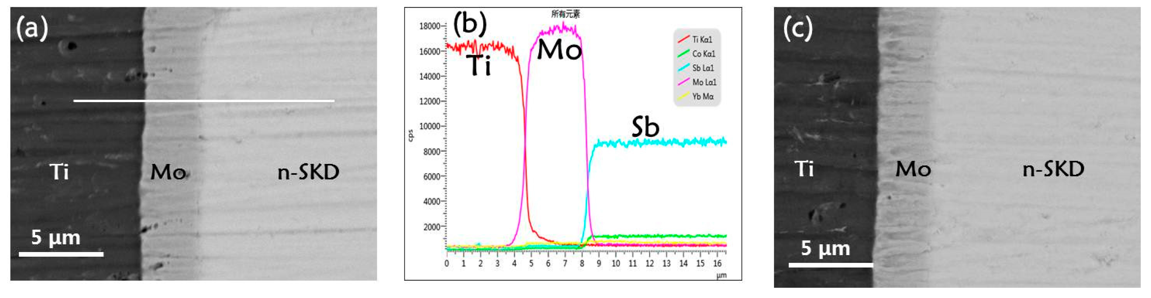
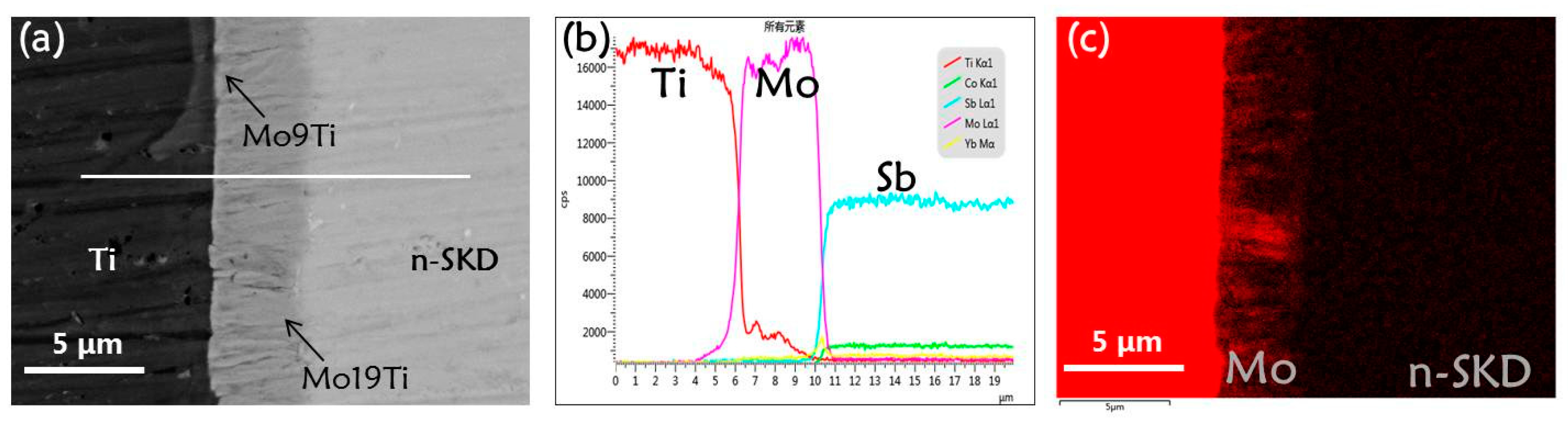
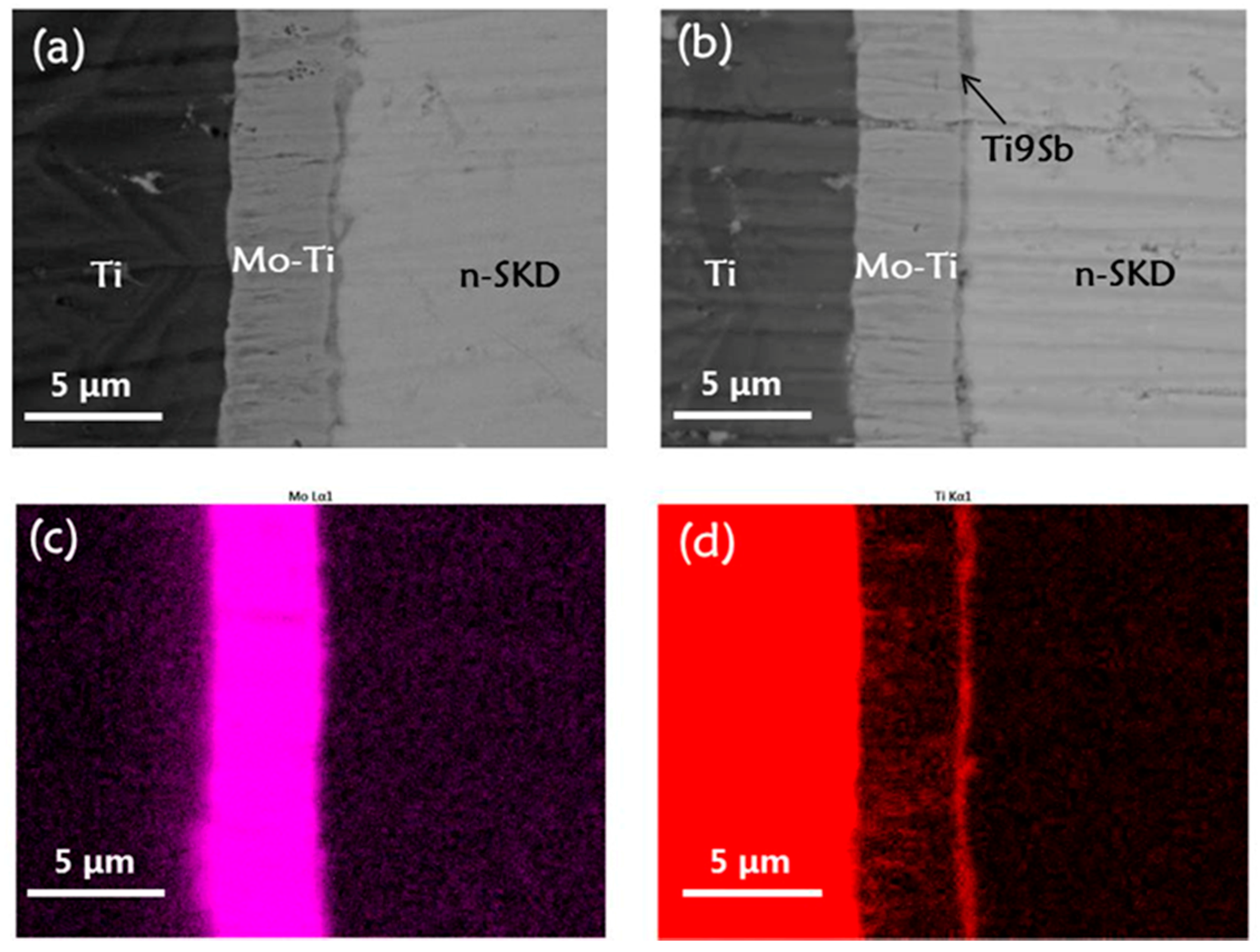
3.2.1. Pretreatment

The Ti/Mo/Yb0.3Co4Sb12 joints were then pretreated by isothermal aging at 550 °C. Figure 3a,b show the BSE graph with spot testing results and line scan results across the interfaces of the joints after 16 days aging, respectively. Figure 3c shows the distribution of the Ti content in the joint and it clearly reveals that some Ti atoms have penetrated across the Mo layer and reached the Yb0.3Co4Sb12 matrix. All the measurement results confirm that the inter-diffusion at the Mo/Yb0.3Co4Sb12 interface is neglectable. However, Ti diffuses across the Ti/Mo interface and moves into the Mo layer, consequently forming a new Mo-Ti layer with a content gradient. In the Mo-Ti layer, the content of Ti decreases from about 10 at % Ti at the Ti/Mo-Ti interface to about 5 at % Ti at the Mo-Ti/Yb0.3Co4Sb12 interface. The contact resistivity of about 3.8 μΩ·cm2 for the pretreated joints is almost the same value as that of the as prepared ones, which indicates that the penetration of the Ti atoms into the Mo layer almost does not affect the apparent contact resistivity of the joints. Furthermore, if one prolongs the pretreatment time, the inter-diffusion between the Ti and Yb0.3Co4Sb12 matrix will surely begin.
Based on the above results, to simplify the study on the interfacial stability, all the following Ti/Mo/Yb0.3Co4Sb12 joints were pretreated at 550 °C for 16 days before they were further isothermally aged. Correspondingly, the structure of the joints after the pretreatments is referred to as Ti/Mo-Ti/Yb0.3Co4Sb12 and the end of the pretreatment is set to be the beginning of the isothermal aging.

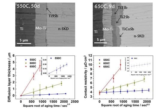
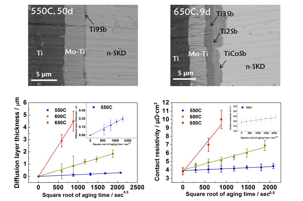
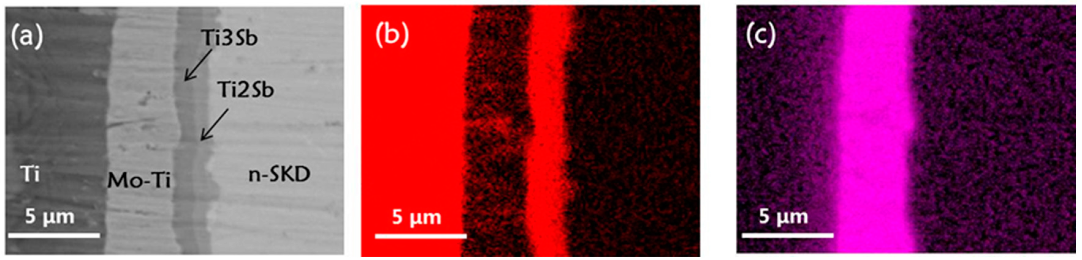
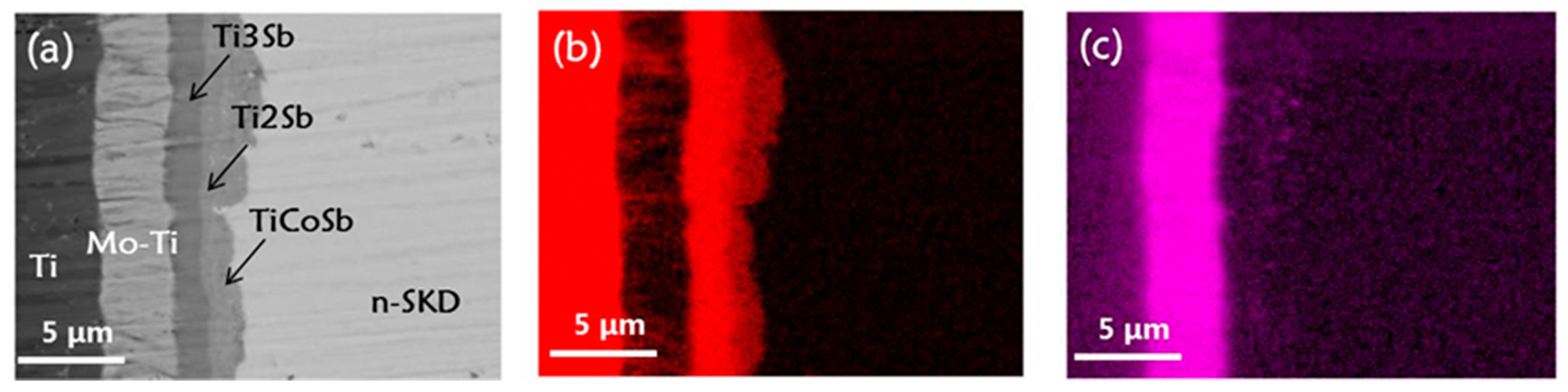
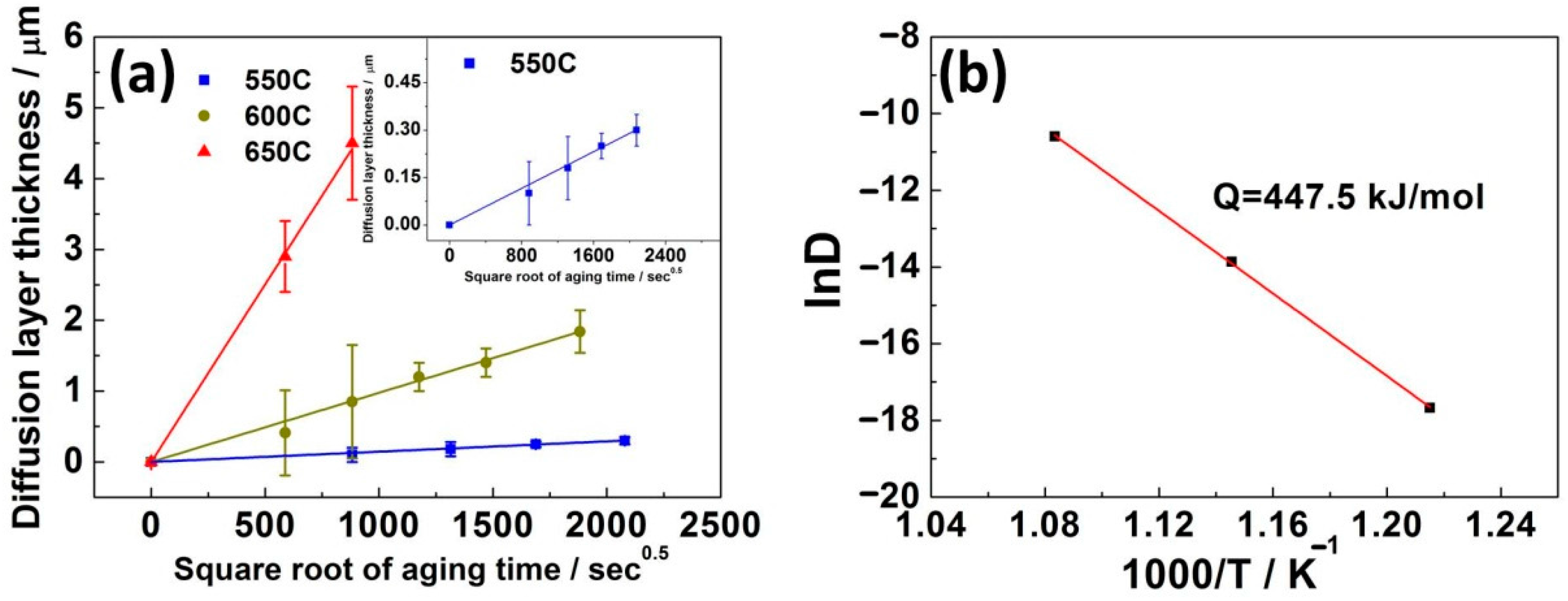
3.2.2. Diffusion Kinetics of the Interface

The pretreated joints were then isothermally aged at 550 °C and the inter-diffusion between Ti and Yb0.3Co4Sb12 occured at the Mo-Ti/Yb0.3Co4Sb12 interface. The BSE graphs of the interfacial cross section for the joints after 20-day and 50-day aging are shown in Figure 4a,b. After being aged for 50 days, the diffusion layer is about 0.3 μm thick and consists of about 90 at % Ti and 10 at % Sb without any sign of Mo. The extremely slow growth-speed of the diffusion layer implies that the new Mo-Ti layer formed in the pretreatment effectively dampens the diffusion of Ti atoms before they reach the Yb0.3Co4Sb12 matrix. Besides, Figure 4c,d show that there is no evident change in the distribution of Ti and Mo in the formed Mo-Ti layer, compared to the pretreated joints.
The pretreated joints were also isothermally aged at 600 °C and 650 °C. It was found that the growth rate of the diffusion layer between Ti and Yb0.3Co4Sb12 increases with an increasing aging temperature. According to Figure 5, after being aged at 600 °C for 41 days, the diffusion layer at the Mo-Ti/Yb0.3Co4Sb12 interface reaches about 2 μm and consists of two sub-layers of Ti3Sb and Ti2Sb. Figure 6 shows that after being aged for nine days at 650 °C, the total thickness of the diffusion layer at the Mo-Ti/Yb0.3Co4Sb12 interface grows to about 4.5 μm. Beside the sub-layers of Ti3Sb and Ti2Sb, there also appears a sign of TiCoSb in the front of the diffusion layer.
To reveal the diffusion kinetics, we analyzed the relationship between the total diffusion layer thickness, aging time, and aging temperature. Figure 7a shows that at all the three aging temperatures, the total thickness of the diffusion layer is linear with the square root of the aging time, which indicates that the evolution of the Mo-Ti/Yb0.3Co4Sb12 interface is a diffusion-controlling process between 550 °C and 650 °C. Therefore, the diffusion layer thickness can be expressed by the following parabolic equation [38,39]:
Y Y 0 = ( D t ) 0.5
where t is the aging time, and Y0 and Y are the total diffusion layer thickness at the origin of aging and after being aged for a time period of t, respectively. D is the growth rate of the diffusion layer, which is a function of the aging temperature. By fitting the data of the diffusion layer thickness as a function of t0.5, D0.5, which is the slope of the fitting result, can be obtained.
To determine the activation energy for the interfacial diffusion, the Arrhenius relationship was used,
D = D 0 exp ( Q R T )
where D0 is the growth constant, Q is the apparent activation energy for the growth of the total diffusion layer, T is the temperature in Kelvin, and R is the gas constant, 8.314 J/(mol∙K). Equation (2) can be transformed into:
ln D = Q 1000 R · 1000 T + D 0
By plotting and fitting lnD against 1000/T, Q can be obtained. Table 1 shows detailed D values and relations between the diffusion layer thickness and aging time. As is shown in Figure 7b, based on Table 1 and Equation (3), the activation energy Q for the growth of the diffusion layer at the Mo-Ti/Yb0.3Co4Sb12 interface is calculated to be about 447.5 kJ/mol at the temperature range of 550 °C to 650 °C. Combined with the above results, the variation of the diffusion layer thickness at the Mo-Ti/Yb0.3Co4Sb12 interface can be predicted over the above temperature range.

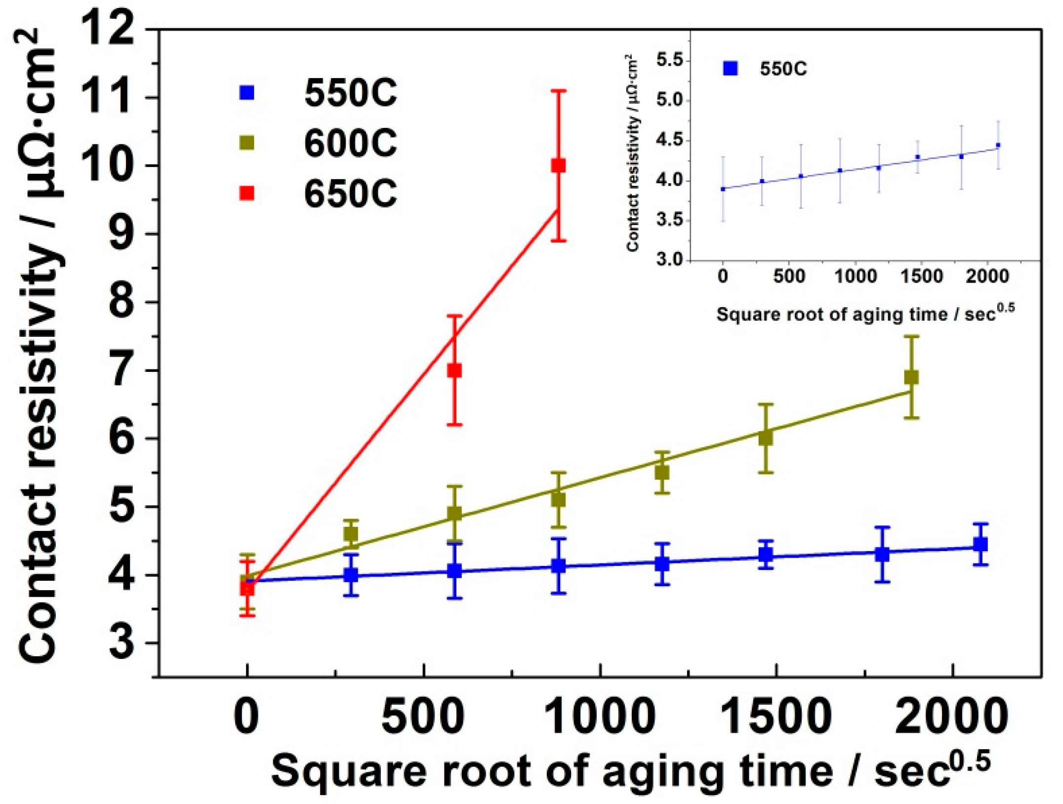
3.2.3. Stability of the Contact Resistivity and Service Life Prediction

To study the high temperature stability of the electrical properties of these joints, the contact resistivity of the joints was measured after each different thermal aging time. Figure 8 exhibits the variation of the interfacial contact resistivity of the joints with the square root of the aging time between 550 °C and 650 °C. At the aging temperature of 550 °C, the contact resistivity of the joint increases very slowly and reaches about 4.5 μΩ·cm2 after being aged for 50 days. Increasing the aging temperature to 600 °C and 650 °C, the contact resistivity reaches 6.8 μΩ·cm2 and 10 μΩ·cm2 after 41 days and nine days, respectively. In contrast to the previous reports [26,29,30,31], the stability of the contact resistivity of the Ti/Mo/Yb0.3Co4Sb12 joints is significantly improved.
The variation of the contact resistivity was then fitted with the square root of the aging time and a linear relationship between them was found (See Table 2). Based on Table 1 and Table 2, it is clear that the increase in the contact resistivity of the Ti/Mo-Ti/Yb0.3Co4Sb12 joints corresponds well to the increase in the thickness of the interfacial diffusion layer at the Mo-Ti/Yb0.3Co4Sb12 interface. In another word, it is the growth of the interfacial diffusion layer at the Mo-Ti/Yb0.3Co4Sb12 interface that dominates the stability of the interfacial contact resistivity of the Ti/Mo-Ti/Yb0.3Co4Sb12 joints.
The performance of the TE joints, as well as that of the TEGs, is sensitive to the contact resistivity, and therefore, the contact resistivity is a valuable criteria for the service life prediction of the TE joints. We assume that a Ti/Mo/Yb0.3Co4Sb12 joint fails when the interfacial contact resistivity reaches 10 μΩ·cm2 or 20 μΩ·cm2, which are low values and satisfy most practical applications, and the service life of the joint is then predicted in Table 2. At the service temperature of 550 °C, the pretreated Ti/Mo/Yb0.3Co4Sb12 joints can endure about 21 years before the contact resistivity reaches 10 μΩ·cm2. Even when increasing the service temperature to 600 °C, the joints can survive for 3.9 years before the contact resistivity reaches 20 μΩ·cm2.

4. Conclusions

In this paper, we successfully designed and fabricated n-type SKD thermoelectric joints with the sandwich structures of Ti/Mo/Yb0.3Co4Sb12. With a controlled Mo layer thickness and the buffering of the Ti layer, the interfaces of the joints bond well and can survive severe thermal shocking. During isothermal aging at the temperature range of 550 °C to 650 °C, Ti penetrates across the Mo layer and diffuses into the Yb0.3Co4Sb12 matrix. The interfacial evolution at the formed Mo-Ti/Yb0.3Co4Sb12 interface is found to be a diffusion-controlling process. Diffusion kinetics between Ti and Yb0.3Co4Sb12 at the Mo-Ti/Yb0.3Co4Sb12 interface were investigated and the apparent activation energy for the growth of the diffusion layer was obtained. Meanwhile, it was also found that the inter-diffusion between Ti and Yb0.3Co4Sb12 is the decisive factor in the rise of the contact resistivity. Because of the damping of the formed Mo-Ti layer, the diffusion of Ti towards the Yb0.3Co4Sb12 is greatly decelerated and the inter-diffusion between the Ti and the Yb0.3Co4Sb12 matrix is extremely slow. As a result, the Ti/Mo/Yb0.3Co4Sb12 joints demonstrate the excellent stability of the contact resistivity. Based on the stability of the contact resistivity, service life prediction of the joints was made, and the result shows that the Ti/Mo/Yb0.3Co4Sb12 joint is a qualified choice and a promising candidate for practical applications at 550 °C and 600 °C in vacuum, respectively.

Acknowledgments

The authors acknowledge the financial supports from the National Natural Science Foundation of China (Contract No. 51404236, 51572282 and 51372261).

Author Contributions

Ming Gu conceived, designed, and performed the experiments, analyzed the data and wrote the paper. Shengqiang Bai instructed the designing of the experiments, the analyses of the data, and the writing of the paper. Xugui Xia helped to perform the experiments and analyses of the data. Xiangyang Huang and Xiaoya Li supported the analyses of the data through valuable discussions. Xun Shi and Lidong Chen supported and provided guideline of the work.

Conflicts of Interest

The authors declare no conflict of interest.

References

  1. Mohamed, S.E.G.; Saber, H.H. High efficiency segmented thermoelectric unicouple for operation between 973 and 300 K. Energy Convers. Manag. 2003, 44, 1069–1088. [Google Scholar]
  2. Mohamed, S.E.G.; Saber, H.H. Thierry Caillat, Efficient segmented thermoelectric unicouples for space power applications. Energy Convers. Manag. 2004, 44, 1755–1772. [Google Scholar]
  3. Salzgeber, K.; Prenninger, P.; Grytsiv, A.; Rogl, P.; Bauer, E. Skutterudites: Thermoelectric Materials for Automotive Applications? J. Electron. Mater. 2010, 39, 2074–2078. [Google Scholar] [CrossRef]
  4. Kumar, S.; Heister, S.D.; Xu, X.; Salvador, J.R. Optimization of thermoelectric components for automobile waste heat recovery systems. J. Electron. Mater. 2015, 44, 3627–3636. [Google Scholar] [CrossRef]
  5. Lu, Z.; Zhang, H.; Mao, C.; Li, C.M. Silk fabric-based wearable thermoelectric generator for energy harvesting from the human body. Appl. Energy 2016, 164, 57–63. [Google Scholar] [CrossRef]
  6. Gelbstein, Y.; Tunbridge, J.; Dixon, R.; Reece, M.J.; Ning, H.P.; Gilchrist, R.; Summers, R.; Agote, I.; Lagos, M.A.; Simpson, K.; et al. Physical, mechanical and structural properties of highly efficient nanostructured n- and p- silicides for practical thermoelectric applications. J. Electron. Mater. 2014, 43, 1703–1711. [Google Scholar] [CrossRef]
  7. Joshi, G.; Lee, H.; Lan, Y.; Wang, X.; Zhu, G.; Wang, D.; Gould, R.W.; Cuff, D.C.; Tang, M.Y.; Dresselhaus, M.S.; et al. Enhanced thermoelectric figure-of-merit in nanostructured p-type silicon germanium bulk alloys. Nano Lett. 2008, 8, 4670–4674. [Google Scholar] [CrossRef] [PubMed]
  8. Wang, X.W.; Lee, H.; Lan, Y.C.; Zhu, G.H.; Joshi, G.; Wang, D.Z.; Yang, J.; Muto, A.J.; Tang, M.Y.; Klatsky, J.; et al. Enhanced thermoelectric figure of merit in nanostructured n-type silicon germanium bulk alloy. Appl. Phys. Lett. 2008, 93, 193121. [Google Scholar]
  9. Yang, X.; Wu, J.; Ren, D.; Zhang, T.; Chen, L. Microstructure and Thermoelectric Properties of p-type Si80Ge20B0.6-SiC Nanocomposite. J. Inorg. Mater. 2016, 31, 997–1003. [Google Scholar]
  10. Appel, O.; Schwall, M.; Kohne, M.; Balke, B.; Gelbstein, Y. Effects of microstructural evolution effects on the thermoelectric properties of spark plasma sintered Ti0.3Zr0.35Hf0.35NiSn half-Heusler compound. J. Electron. Mater. 2013, 42, 1340–1345. [Google Scholar] [CrossRef]
  11. Appel, O.; Zilber, T.; Kalabukhov, S.; Beeri, O.; Gelbstein, Y. Morpholoical effects on the thermoelectric properties of Ti0.3Zr0.35Hf0.35Ni1+δSn alloys following phase separation. J. Mater. Chem. 2015, 3, 11653–11659. [Google Scholar]
  12. Vizel, R.; Bargig, T.; Beeri, O.; Gelbstein, Y. Bonding of Bi2Te3 based thermoelectric legs to metallic contacts using Bi0.82Sb0.18 alloy. J. Electron. Mater. 2016, 45, 1296–1300. [Google Scholar] [CrossRef]
  13. Lee, M.H.; Rhyee, J.; Kim, S.; Choa, Y. Thermoelectric properties of Bi0.5Sb1.5Te3/Ag2Te bulk composites with size- and shape-controlled Ag2Te nano-particles dispersion. J. Alloys Compd. 2016, 657, 639–645. [Google Scholar] [CrossRef]
  14. Sumithra, S.; Takas, N.J.; Misra, D.K.; Nolting, W.M.; Poudeu, P.F.P.; Stokes, K.L. Enhancement in thermoelectric figure of merit in nanostructured Bi2Te3 with semimetal nanoinclusions. Adv. Energy Mater. 2011, 1, 1141–1147. [Google Scholar] [CrossRef]
  15. Mei, D.; Li, Y.; Yao, Z.; Wang, H.; Zhu, T.; Chen, S. Enhanced thermoelectric performance of n-type PbTe bulk materials fabricated by semisolid powder processing. J. Alloys Compd. 2014, 609, 201–205. [Google Scholar] [CrossRef]
  16. Li, J.Q.; Lu, Z.W.; Li, S.M.; Liu, F.S.; Ao, W.Q.; Li, Y. High thermoelectric properties of PbTe-Sm2Se3 composites. Scr. Mater. 2016, 112, 144–147. [Google Scholar] [CrossRef]
  17. Gelbstein, Y. Pb1−xSnxTe Alloys—Application Considerations. J. Electron. Mater. 2011, 40, 533–536. [Google Scholar] [CrossRef]
  18. Gelbstein, Y. Phase morphology effects on the thermoelectric properties of Pb0.25Sn0.25Ge0.5Te. Acta Mater. 2013, 61, 1499–1507. [Google Scholar] [CrossRef]
  19. Dado, B.; Gelbstein, Y.; Mogilansky, D.; Ezersky, V.; Dariel, M.P. Structural evolution following spinodal decomposition of the pseudo-ternary compound (Pb0.3Sn0.1Ge0.6)Te. J. Electron. Mater. 2010, 39, 2165–2171. [Google Scholar] [CrossRef]
  20. Hazan, E.; Ben-Yehuda, O.; Madar, N.; Gelbstein, Y. Functional graded germanium-lead chalcogenides-based thermoelectric module for renewable energy applications. Adv. Energy Mater. 2015, 5. [Google Scholar] [CrossRef]
  21. Chen, L.; Backhaus-Ricoult, M.; He, L.; Li, X.; Xia, X.; Zhao, D. Fabrication Method for Thermoelectric Device. U.S. Patent US8198116 B2, 12 June 2012. [Google Scholar]
  22. Ting, W.; Bai, S.; Shi, X.; Chen, L. Enhanced Thermoelectric Properties of BaxEuyCo4Sb12 with Very High Filling Fraction. J. Inorg. Mater. 2013, 28, 224–228. [Google Scholar]
  23. Muto, A.; Yang, J.; Poudel, B.; Ren, Z.; Chen, G. Skutterudite unicouple characterization for energy harvesting applications. Adv. Energy Mater. 2013, 3, 245–251. [Google Scholar] [CrossRef] [Green Version]
  24. Alleno, E.; Lamquembe, N.; Cardoso-Gil, R.; Ikeda, M.; Widder, F.; Rouleau, O.; Godart, C.; Grinl, Y.; Paschen, S. A thermoelectric generator based on an n-type clathrate and a p-type skutterudite unicouple. Phys. Status Solidi A 2014, 1, 1293–1300. [Google Scholar] [CrossRef]
  25. Salvador, J.R.; Cho, J.Y.; Ye, Z.; Moczygemba, J.E.; Thompson, A.J.; Sharp, J.W.; Koenig, J.; Maloney, R.; Thompson, T.; Sakamoto, J.; et al. Conversion efficiency of skutterudite-based thermoelectric modules. Phys. Chem. Chem. Phys. 2014, 16, 12510–12520. [Google Scholar] [CrossRef] [PubMed]
  26. Tang, Y.; Bai, S.; Ren, D.; Liao, J.; Zhang, L.; Chen, L. Interface Structure and Electrical Property of Yb0.3Co4Sb12/Mo-Cu Element Prepared by Welding Using Ag-Cu-Zn Solder. J. Inorg. Mater. 2015, 30, 256–260. [Google Scholar]
  27. Fan, J.; Chen, L.; Bai, S.; Shi, X. Joining of Mo to CoSb3 by spark plasma sintering by inserting a Ti interlayer. Mater. Lett. 2004, 58, 3876–3878. [Google Scholar] [CrossRef]
  28. Zhao, D.; Li, X.; He, L.; Jiang, W.; Chen, L. Interfacial evolution behavior and reliability evaluation of CoSb3/Ti/Mo-Cu thermoelectric joints during accelerated thermal aging. J. Alloys Compd. 2009, 477, 425–431. [Google Scholar] [CrossRef]
  29. Zhao, D.; Li, X.; He, L.; Jiang, W.; Chen, L. High temperature reliability evaluation of CoSb3/electrode thermoelectric joints. Intermetallics 2009, 17, 136–141. [Google Scholar] [CrossRef]
  30. Gu, M.; Xia, X.; Li, X.; Huang, X.; Chen, L. Microstructural evolution of the interfacial layer in the Ti-Al/Yb0.6Co4Sb12 thermoelectric joints at high temperature. J. Alloys Compd. 2014, 610, 665–670. [Google Scholar] [CrossRef]
  31. Fan, X.C.; Gu, M.; Shi, X.; Chen, L.D.; Bai, S.Q.; Nunna, R. Fabrication and reliability evaluation of Yb0.3Co4Sb12/Mo–Ti/Mo–Cu/Ni thermoelectric joints. Ceram. Int. 2015, 41, 7590–7595. [Google Scholar] [CrossRef]
  32. Bae, K.H.; Choi, S.; Kim, K.; Choi, H.; Seo, W.; Kim, I.; Lee, S.; Hwang, H.J. Power-Generation Characteristics After Vibration and Thermal Stresses of Thermoelectric Unicouples with CoSb3/Ti/Mo(Cu) Interfaces. J. Electron. Mater. 2015, 44, 2124–2131. [Google Scholar] [CrossRef]
  33. Zhao, X.Y.; Shi, X.; Chen, L.D.; Zhang, W.Q.; Zhang, W.B.; Pei, Y.Z. Synthesis and thermoelectric properties of Sr-filled skutterudite SryCo4Sb12. J. Appl. Phys. 2006, 99, 053711. [Google Scholar] [CrossRef]
  34. Gu, M.; Xia, X.; Huang, X.; Bai, S.; Li, X.; Chen, L. Study on the interfacial stability of p-type Ti/CeyFexCo4−xSb12 thermoelectric joints at high temperature. J. Alloys Compd. 2016, 671, 238–244. [Google Scholar] [CrossRef]
  35. PLANSEE. Available online: https://www.plansee.com/en/materials/molybdenum.html (accessed on 22 August 2017).
  36. Hahn, T.A. Thermal Expansion of Copper from 20 to 800 K—Standard Reference Material 736. J. Appl. Phys. 1970, 41, 5096–5101. [Google Scholar] [CrossRef]
  37. Abdullaev, R.N.; Kozlovskii, Y.M.; Khairulin, R.A.; Stankus, S.V. Density and Thermal Expansion of High Purity Nickel over the Temperature Range from 150 K to 2030 K. Int. J. Thermophys. 2015, 36, 603–619. [Google Scholar] [CrossRef]
  38. Yu, D.Q.; Wang, L. The growth and roughness evolution of intermetallic compounds of Sn–Ag–Cu/Cu interface during soldering reaction. J. Alloys Compd. 2008, 458, 542–547. [Google Scholar] [CrossRef]
  39. Sun, P.; Andersson, C.; Wei, X.; Cheng, Z.; Shangguan, D.; Liu, J. Study of interfacial reactions in Sn–3.5Ag–3.0Bi and Sn–8.0Zn–3.0Bi sandwich structure solder joint with Ni(P)/Cu metallization on Cu substrate. J. Alloys Compd. 2007, 437, 169–179. [Google Scholar] [CrossRef]
Figure 1. Variation of the CTE with temperature for Yb0.3Co4Sb12, Ti, Mo, Cu, and Ni, Data for Mo, Cu, and Ni are from references [35,36,37] respectively.
Applsci 07 00952 g001
Figure 2. The interfacial microstructure of the Ti/Mo/Yb0.3Co4Sb12 joints (a), as prepared, a Back Scattering Electron (BSE) graph, (b), as prepared, a line scan, and (c), after 10 cycles of thermal shocking between 0 °C and 600 °C, a BSE graph.
Applsci 07 00952 g002
Figure 3. The interfacial microstructure of the Ti/Mo/Yb0.3Co4Sb12 joints pretreated at 550 °C for 16 days. (a) the BSE graph and spot testing, (b) line scan results, (c) the distribution of Ti.
Applsci 07 00952 g003
Figure 4. The interfacial evolution of the pretreated joints isothermally aged at 550 °C. (a) BSE graph, 20 days; (b) BSE graph, 50 days; (c) distribution of Mo, 50 days; (d) distribution of Ti, 50 days.
Applsci 07 00952 g004
Figure 5. The interfacial microstructure of the pretreated joints isothermally aged at 600 °C for 41 days. (a) BSE graph and spot testing, (b) distribution of Ti, (c) distribution of Mo.
Applsci 07 00952 g005
Figure 6. The interfacial microstructure of the pretreated joints isothermally aged at 650 °C for nine days. (a) BSE graph and spot testing, (b) distribution of Ti, (c) distribution of Mo.
Applsci 07 00952 g006
Figure 7. (a) Variation of the diffusion layer thickness of the pretreated joints with the square root of aging time between 550 °C and 650 °C. The inset is the enlargement of the result at 550 °C. (b) Variation of lnD with 1000/T between 550 °C and 650 °C.
Applsci 07 00952 g007
Figure 8. Variation of the interfacial contact resistivity of the joints with the square root of the aging time between 550 °C and 650 °C.
Applsci 07 00952 g008
Table 1. Fitting results of the growth rate and the relationship between diffusion layer thickness and aging time (s).
Temperature/°CD/10−19 m2/sY/μm
5500.211.45 × 10−4t0.5
6009.539.76 × 10−4t0.5
65025150.1 × 10−4t0.5
Table 2. Fitting results of the relationship between the contact resistivity and the aging time, and predicted service life (The prediction is based on the assumption that a joint fails when the contact resistivity reaches 10 μΩ·cm2 (a) and 20 μΩ·cm2 (b)).
Temperature/°CContact Resistivity/μΩ∙cm2Predicted Service Life (a)/dayPredicted Service Life (b)/day
5502.37 × 10−4t0.5 + 3.91764253,346
60014.1 × 10−4t0.5 + 3.992011431
65063.5 × 10−4t0.5 + 3.761175

