Article

Investigation on Coal Fragmentation by High-Velocity Water Jet in Drilling: Size Distributions and Fractal Characteristics

1
State Key Laboratory of Coal Mine Disaster Dynamics and Control, Chongqing University, Chongqing 400044, China
2
College of Resources and Environmental Science, Chongqing University, Chongqing 400044, China
3
National & Local Joint Engineering Laboratory of Gas Drainage in Complex Coal Seam, Chongqing University, Chongqing 400044, China
*
Author to whom correspondence should be addressed.
Submission received: 14 September 2018 / Revised: 9 October 2018 / Accepted: 16 October 2018 / Published: 19 October 2018
(This article belongs to the Special Issue Green Energy and Applications)

Abstract

:
Water jet drilling (WJD) technology is a highly efficient method to extract coalbed methane from reservoirs with low permeability. It is crucial to efficiently remove the coal fragments while drilling. In this study, to disclose coal fragmentation features and size distributions under water jet impact in drilling, the image processing method was utilized to obtain the geometric dimensions of coal fragments. The size distributions, morphologies and fractal characteristics of coal fragmentation were studied based on generalized extreme value distribution and fractal theory. The effects of the jet impact velocity and coal strength on the fragmentation features were analyzed. The results show that fine particles dominate the coal fragments in WJD for coal seams with various strengths. In experiments conducted at the Fengchun coal mine, owing to the higher coal strength of the M7 coal seam, the fragmentation degree of coal subjected to water jets during WJD is lower in the M7 coal steam than in the M8 coal seam, which results in a large dominant fragment size and small fractal dimension under the same impact energy. It was found that the higher the jet impact velocity is, the higher the quantity of fragments generated from WJD and the smaller the particle size. The NUM-based cumulative probability distribution curves of coal fragments are more intensive in the range of relatively small particle sizes and then become sparser with the increase in particle size. When the impact velocity increases, (i) the size distribution curves move toward smaller particle sizes, and the dominant fragment size decreases; (ii) the shape (major axis/minor axis) of coal fragments move toward the upper left, and the curve shape for a high impact velocity attains unity more quickly; and (iii) the fractal dimension value increases linearly. In addition, the fractal dimensions are obviously affected by the dominant fragment size; they increase with the decrease in the dominant fragment size. This study can provide a basis for further research on coal fragment transportation in WJD and parameter selection for discharging coal fragments during drilling for CBM development.

1. Introduction

Coalbed methane (CBM) is an efficient and clean energy resource. Chinese CBM reserves above 2000 m are estimated to be 36.81 trillion m3, which ranks third globally after Russia and Canada [1,2]. However, the methane in coal seams easily induces mine disasters, such as coal and gas outbursts and gas explosions [3]. Therefore, the effective extraction of CBM is not only of considerable significance for meeting the global energy demand for sustainable development, but also necessary for improving coal mine safety and reducing greenhouse gas emissions [2,4,5]. Unfortunately, CBM reservoirs in China are characterized by low saturation, low permeability, low reservoir pressure, and relatively high metamorphic grade, resulting in a low CBM production rate [6,7,8]. Thus, some measures must be taken to improve the permeability of coal seams by increasing the number of cracks and amount of gas desorption in coal. Water jet drilling (WJD) technology is a highly efficient new method to develop oil and gas for reservoirs with low permeability [9,10,11]. For the ground and underground CBM development, WJD is designed to create multiple lateral micro-holes or gas drainage boreholes in the CBM reservoir, respectively, utilizing high-pressure water jets to break the coal formation. This enables the gas formation to be exposed as much as possible, and it has been effective in developing unconventional resources such as CBM and shale gas in many countries [12].
It is necessary to remove the coal fragments effectively from the micro-holes in order to reduce the resistance to the bit and working pipes and form a long hole in the formation. However, the coal fragments generated by WJD are larger, more irregular, and are shaped like lumps compared with the cuttings generated by the traditional mechanical drilling method. This makes it more difficult for WJD holes to discharge coal fragments. For the cuttings generated by a mechanical drill bit, there have been many studies to investigate the transportation of cuttings in the well and the effects of drilling parameters on cutting transportation, including pump rate, well dimensions, fluid properties, solid sizes, solid loading and well inclination [13,14,15,16,17,18]. However, the coal fragments generated from WJD are the results of coal fragmentation under multiple water jet impact. There are few studies that analyze the coal fragment transportation in WJD holes, and there is a lack of understanding regarding the fragmentation features of coal fragments, including the particle size distribution and morphology. Moreover, the fragment sizes and shapes have a dramatic influence on fragments transportation in WJD holes. The large coal fragments are difficult to discharge from the hole with water flow, resulting in sticking and serious friction resistance [19,20]. Therefore, it is very necessary to study the fragmentation size distribution characteristics of coal generated from WJD.
Research on the fragmentation size distribution characteristics for brittle materials has become a popular field of study [21,22]. The fragments can be described by some statistical regularity. Rosin-Rammler and Weibull distribution functions are usually used to represent the size distribution of rock fragments [23]. Some models have been proposed to predict the mean fragment size for impact fragmentation and rock blast fragmentation [24,25]. The three-parameter generalized extreme value distribution (GEV) can suitably describe the frequency distribution of fragment sizes generated from impact test using an SHPB [21,26]. Along with the development of fractal geometry theory, the fractal theory was gradually used to study the particle size distributions [21,27,28]. However, coal fragmentation under water jet impact loading in WJD is a very complicated process because of the hydromechanical coupling effect, which makes coal breakage different from other impact failure patterns [29,30,31]. Thus, it is worth investigating the coal fragmentation features in order to provide the basis for further research on the coal fragments transportation in WJD.
The objective of this work is to disclose the size distribution characteristics of coal fragmentation subjected to high-pressure water jets in WJD. The image processing method based on MATLAB was utilized to obtain the geometric dimensioning of coal fragments. The size distributions, morphology and fractal characteristics of coal fragments were investigated based on the three-parameter GEV function and fractal theory. The effects of the jet impact velocity and coal strength on the size distributions and fractal characteristics were studied. This study can provide a guide for studying the coal fragments transportation and selecting the parameters of discharging the coal fragments from holes in WJD for CBM development.

2. Material and Methods

It is well known that it is very difficult for a laboratory to simulate the original in situ stress of coal, which causes the coal mass impacted by water jets to split and produce fragments [32,33]. There are distinct differences between coal fragments that are under crustal stress conditions and those that are not. This makes it difficult to effectively analyze the size distribution and morphology of coal fragments in practical WJD engineering applications. In this study, in order to obtain the actual coal fragments generated from WJD, WJD experiments for various coal mass strengths and jet velocities were conducted.

2.1. Experimental System and Equipments

The experimental system of WJD is mainly composed of a high-pressure pump, water tank, pressure control system, winch, flexible high-pressure hose, collection box for coal fragments and a water-jet bit (Figure 1). The high-pressure pump used in this water jet drilling experiment is a five-plunger high-pressure pump with a rated pressure of 56 MPa and a rated flow of 200 L/min. A pressure control system is used to adjust the system pressure conveniently, which includes a relief valve and a pressure gauge. The flexible high-pressure hose is used as the working pipe to convey high-pressure working fluid to break coal, and it has an ID of 10 mm, an OD of 17 mm, a minimum bending radius of 90 mm, a working pressure of 60 MPa and a bursting pressure of 135 MPa. To twine the flexible high-pressure hose in an orderly fashion, a winch is adopted to realize the high-pressure water transmission between the linear motion of high-pressure water pipe and the circumference roll of winch through the high-pressure sealing rotator.
As the most critical component of WJD system, the water-jet bit generates high-velocity water jets to break coal and form a CBM extraction borehole or microwell. Owing to the advantages of a simple structure, compact body, low energy consumption, and high rock-breaking efficiency, the multi-nozzle bit is most commonly utilized in WJD operation [10,34]. Thus, the self-propelled multi-nozzles bit is adopted in this WJD experiment. The multi-nozzle bit has one center nozzle, four forward lateral nozzles with an axial diffusion angle of 25°, and eight backward nozzles with an axial diffusion angle of 30° [35,36]. The nozzle diameter is 0.8 mm, as shown in Figure 2. The working principle of breaking coal to form a borehole for the multi-nozzle bit is as follows: the forward nozzles (including center nozzle and lateral nozzles) generate high-velocity jets to break up the coal in front of it and form a hole, whereas the backward nozzles form backward jets to generate the self-propelled force to pull the hose moving forward and have the functions of further breaking coal to expand the borehole diameter and discharging slags. The coal fragments formed in WJD are collected in a box through a filter net of 0.075 mm.

2.2. Experimental Procedures

The jet impact velocity is the most important hydraulic parameter in WJD, and determines the jet impact energy and erosion ability of water jets. The coal strength is a key parameter used to assess the ability of the coal to resist destruction. Thus, this paper focuses on the effects of the jet impact velocity and coal strength on the size distributions of coal fragments in WJD. The WJD field trials were conducted at the +300N1 rock crosscut of Fengchun coal mine in Songzao mining area (Figure 3), the aim of which is to uncover the coal seams. The geological histogram at the +300N1 rock crosscut is shown in Figure 3a, of which the coal seams and rock strata are stable with a simple structure and an average strata occurrence of 290°∠46° and are not affected by faults or magmatic intrusions. Additionally, the there is a simple hydrogeological condition at +300N1 rock crosscut, which is not affected by surface water and karst fissure water. The target coal seams for WJD are the M7 and M8 coal seams (Figure 3c). The occurrence conditions and properties of coal seams are listed in Table 1. The M7 coal seam is hard and massive with a metallic luster and a Protodyakonov coefficient of 1.1, whereas the M8 coal seam is soft in a granular, with a metallic luster and a Protodyakonov coefficient of 0.5. WJD experiments were carried out on the M7 and M8 coal seams, with a drilling time for each borehole of 10 min. The jet velocities were set to 219 m/s, 237 m/s, 253 m/s and 268 m/s. The coal fragments collected in WJD were dried in a baking chamber at 105 °C for 24 h. Subsequently, fragments of each borehole were sieved by utilizing standard sieves with hole diameters of 0.3 mm, 0.5 mm, 1.0 mm, 3.0 mm, 6.0 mm and 12 mm.

2.3. Determination of Fragment Size and Shape Distributions

Obtaining the geometric dimensioning of coal fragments is very important and crucial. In this work, an image processing method developed using MATLAB was used [21,26]. First, coal fragments generated from WJD were sieved into seven different degrees by using standard sieves, and the weight of each degree was measured using a high-precision electronic scale. The coal fragments with particle sizes of less than 0.3 mm were excluded before image processing, because fragments with particle sizes less than 0.3 mm account for a small proportion of the total fragments; Generally less than 30%, as listed in Table 2. These tiny fragments have little effect on discharging coal fragments in WJD due to the large flow rate and annular cross section. Moreover, the tiny fragments less than 0.3 mm cannot be identified from the electronic image, and it is difficult to obtain their geometric dimensioning. Next, a certain percentage of the fragments in each grade were chosen randomly and were poured onto standard white A4 paper with dimensions of 297 × 210 mm, and their photographs were captured by a digital camera (Figure 4a). Next, these photographs were converted into binary images with a pure black background and bright white coal particles based on the median filter method (Figure 4b). Finally, by adopting the functions of regionprops and minboundrect, the geometric dimensions including the area Ai (the projected area of a particle), the major axis limax (the longest axis of the minimum enclosing rectangle of a particle) and the minor axis limin (the axis perpendicular to the major axis) can be determined, as shown in Figure 5.
In this study, an equivalent diameter Die of a circle with the same area as the projected area of the fragment was determined as the fragment size [37], and a shape coefficient κ (the ratio of the major axis to the minor axis) was used to describe the characteristics of each fragment. They can be calculated as follows:
D i e = 2 ( A i / π ) 1 / 2
κ = l i max / l i min
where Die is the equivalent diameter, mm; Ai is the area of each coal fragment, mm2; κ is the shape coefficient; and limax and limin are the longest and minor axis, respectively, of the minimum enclosing rectangle of each particle, mm.

2.4. Characterization of Fragment Size and Shape Distributions

The determination of distribution models is the key to characterizing the size distribution of coal fragments. In this study, the cumulative distribution model of the generalized extreme value (GEV) distribution and fractal theory are adopted.

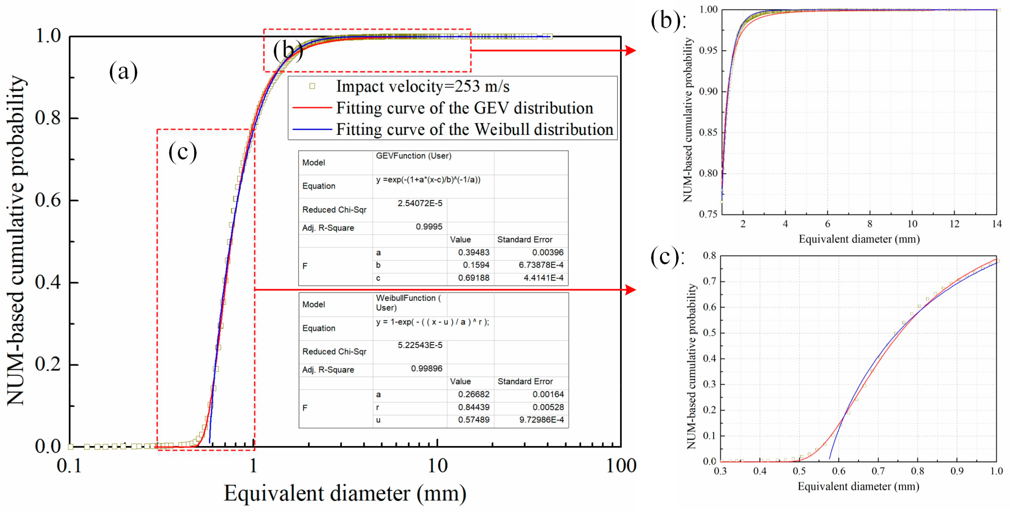
2.4.1. Generalized Extreme Value (GEV) Distribution

Some methods have been proposed to describe the particle size distributions, such as GEV [38], Rayleigh [39], Weibull [23] and log-normal distributions [40]. This paper uses the three-parameter GEV distribution to fit the cumulative probability distribution of coal fragment sizes, similar to the analysis method of experimental results conducted by Hogan [26] and Hou [21]. Because the GEV distribution is a complete set of statistical distributions developed within extreme value theory to combine the Gumbel, Fréchet and Weibull distributions, also known as type I, II and III extreme value distributions, solving the limitation of one type of extreme value distribution function [38]. As shown in Figure 6, taking the coal fragments under an impact velocity of 253 m/s as an example, the three-parameter GEV distribution and Weibull distribution models are used to fit the cumulative probability of coal fragmentation. The fitting results illustrate that both distribution models can describe the cumulative probability distribution of coal fragments for most particle size ranges, such as 0.6–5.0 mm; and the fitting correlation coefficients of both curves are more than 0.99. However, the size scope of the application for GEV distribution function is wider than that for the Weibull distribution, especially for coal fragments with small particle sizes. It can be seen that from the partial magnification in Figure 6b,c that the Weibull distribution model cannot describe the cumulative distribution of coal fragments smaller than 0.55 mm, and the fitted cumulative probability will reach a stead value of 1 when the fragment size is larger than 5.5 mm. Moreover, as shown in Figure 6 b, the GEV distribution model is more suitable for characterizing the size distribution of the small-sized particles. The same phenomenon also appears for other coal fragments in WJD under different jet impact velocities and coal strengths. Additionally, the added parameters (μ, σ, and ξ) can characterize the location, scale and shape of distribution curves of fragments under different hydraulic parameters and coal seam properties. Therefore, the GEV distribution model can accurately characterize the size distribution of coal fragments.
The cumulative distribution model of the GEV distribution can be described as follows [39]:
F ( x ; μ , σ , ξ ) = exp { [ 1 + ξ ( x μ σ ) ] 1 / ξ }
where x is the equivalent diameter of fragment, μ is the location parameter, σ is the scale parameter, and ξ is the shape parameter. These parameters must satisfy 1 + ξ ( x μ ) / σ > 0 .
Next, the derivative of Equation (3) is taken, which is the probability density function as shown in Equation (4). The peak values of the distribution curves correspond to the dominant fragment sizes, i.e., the modes of the probability density distribution curves. To a certain extent, the dominant fragment size indicates the centralized distribution of the experimental data. Therefore, it can be used to characterize the distribution of coal fragments subjected to high-pressure water jets in WJD.
f ( x ; μ , σ , ξ ) = 1 σ [ 1 + ξ ( x μ σ ) ] 1 / ξ 1 exp { [ 1 + ξ ( x μ σ ) ] 1 / ξ }

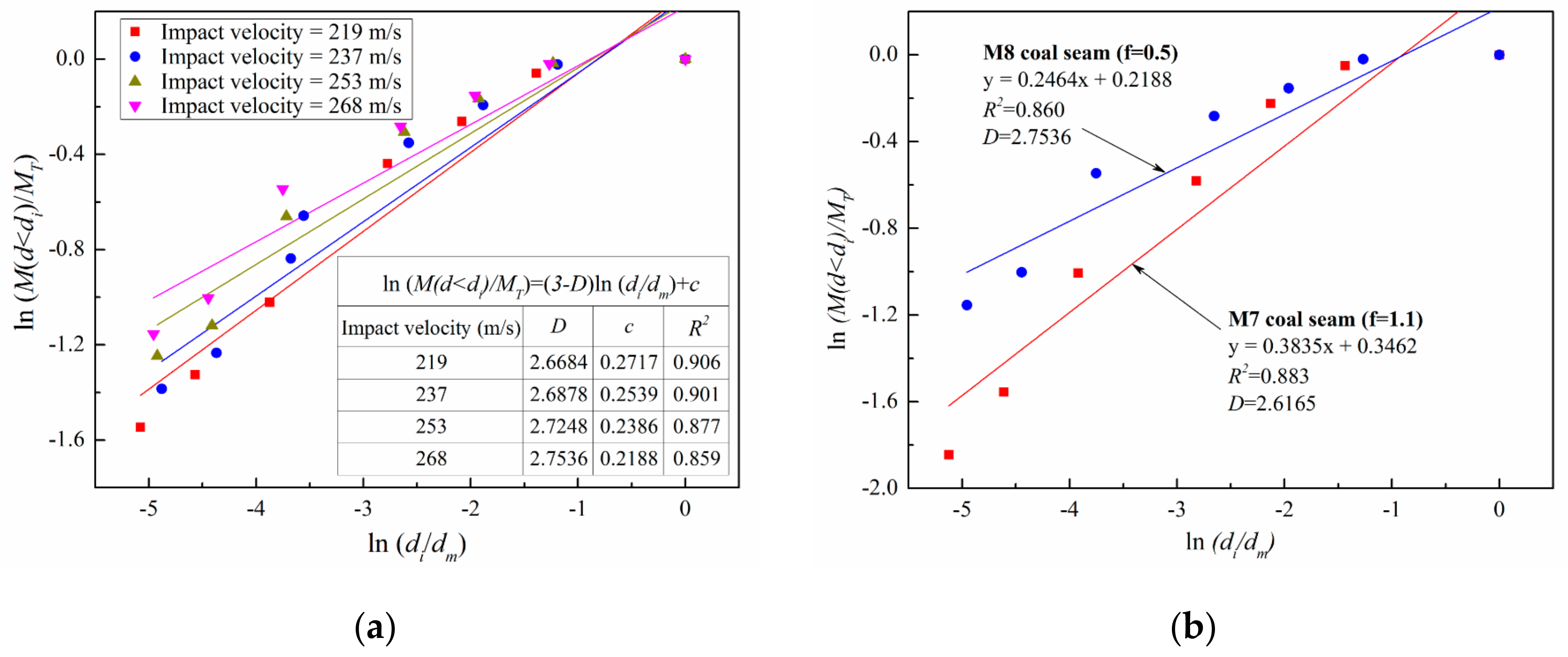
2.4.2. Fractal Model

Fractal theory can quantitatively describe any complex morphology, such as irregular shape, fracture characteristics and distribution features of fragments [29,41,42]. Consequently, the fractal method has been used to investigate the breakage characteristics of coal and rock fragmentation, such as rock burst, blasting, impact loading and uniaxial compression [43,44,45,46,47,48].
The fractal relation of the particle size distribution is generally defined using the relationship between the cumulative numbers of the fragment particles and the grain size in a statistically self-similar system [49]. It can be described using the following equation:
N ( d > d i ) = k d i D
where N ( d > d i ) is the cumulative number of fragments larger than a certain size d i ; k is the number of elements at a unit-length scale; and D is the fractal dimension. The higher the fractal dimension is, the higher the breakage degree of the coal.
However, it is very difficult to estimate the quantities of all fragments and the sizes of each particle. To avoid this problem, Tyler [50] put forward a fractal model of particle size distribution based on the relationship between the cumulative mass and particle size of fragments:
M ( d < d i ) / M T = ( d i / d m ) 3 D
where M ( d < d i ) is the cumulative mass of fragments smaller than d i ; M T is the total mass of coal fragments; and d m is the particle size of the largest fragment.
To better obtain the fractal dimension of coal fragments, a natural logarithm transformation for Equation (6) is made as follows:
ln [ M ( d < d i ) / M T ] = ( 3 D ) ln ( d i / d m )
The fitting line can be displayed in the coordinate system of ln [ M ( d < d i ) / M T ] ~ ln ( d i / d m ) , according to an experimental statistical fragment analysis. The value of (3 − D) in Equation (7) represents the slope of the fitting line, and then, the fractal dimension D can be calculated.

3. Results

3.1. Size Distribution of Fragments
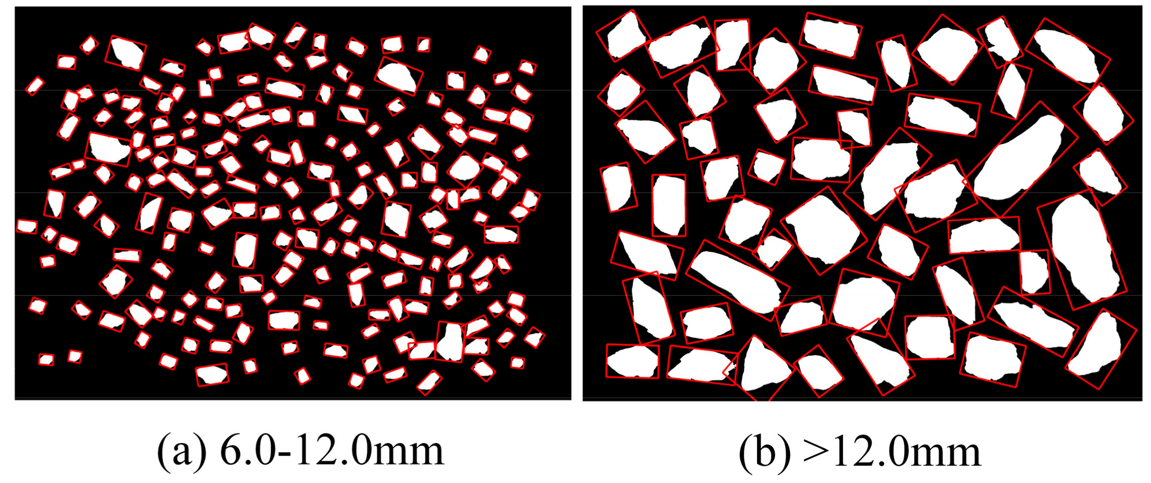
Fragment size not only reveals the fragmentation degree of coal subjected to water jets, but also directly affects the fragment removal efficiency in WJD. The larger the particle sizes of the coal fragments are, the lower the coal fragment removal efficiency is, resulting in the high-pressure hose becoming stuck and the occurrence of high drag [13,51]. Therefore, it is worth investigating the fragment size distribution in WJD.
There are too many coal fragments to obtain the geometric dimensions of each particle, so the sizes and shapes of a certain percentage of fragments in each grade were considered to be the size and shape distributions of the entire grade. Considering the proportion of chosen fragments among all fragments of each grade, the size and shape distributions of all coal fragments generated from each WJD hole can be obtained.
As shown in Figure 7, the cumulative probability distributions based on the particle number (NUM-based cumulative probability) for the equivalent diameters were obtained [21]. The GEV distribution was chosen to fit the data. The fitting correlation coefficients of all the distribution curves were more than 0.98. This indicates that the cumulative distribution model of the GEV distribution is very suitable for characterizing the size distribution of coal fragments. It can be observed from Figure 7 that all the NUM-based cumulative probabilities of coal fragments follow the same change trend: on the one hand, as the particle sizes increase, the distribution curves first increase extremely slowly, then increase rapidly and finally stabilize. For instance, the proportions of fragments with sizes less than 0.6 mm and greater than 2.0 mm are less than 15% and 4%, respectively, whereas the particles with a size of 0.6~2.0 mm account for the vast majority of the total fragments. On the other hand, the distribution fitted curves of coal fragments are more intensive at the section for relatively small particle size. In addition, these curves become sparser with increasing particle sizes. Moreover, the change differences among curves are influenced by the coal properties and the hydraulic parameters of water jets. With the jet velocity increasing, there is an obvious shift of the distribution curves toward smaller sizes (Figure 7a), implying that the average fragment size decreases and most of the fragments decrease as the jet impact velocity increases. It is also observed that the number of coal fragments obtained with high impact velocity is more than that obtained with low velocity. This behavior may be caused by the increasing impact energy magnitude of water jets. Compared with the M8 coal seam, the coal fragment sizes of the M7 coal seam are larger at the same jet impact velocity (Figure 7b). This is because the M7 coal seam has a better ability to resist breakage because of the higher coal strength and fewer joints and fissures inside the coal.
The size distributions of fragments are mainly determined by the dominant fragment size. Therefore, in order to obtain the dominant fragment size for various jet velocities and coal mass strength, the probability density function is obtained as shown in Equation (4). The peak values of curves correspond with the dominant fragment sizes. Figure 8 shows the distribution density for coal fragments of equivalent diameters under various jet velocities and coal strengths. The peak values for each experiment are given in these figures. It can be seen that the distribution density curves move toward the upper left with the increase in jet impact velocity (Figure 8a), whereas the curves move toward the bottom right as the coal mass strength increases (Figure 8b). This indicates that the dominant fragment size increases gradually as the jet impact velocity decreases; the curves become flat, and the particle size range is more scattered. Figure 9 is the relationship between the dominant fragment size and the jet impact velocity in the M8 coal seam. As shown in Figure 9, the dominant fragment size decreases logarithmically with the jet velocity. The magnitude of rock-breaking energy and the damage degree on coal caused by water jet impingement may lead to the above phenomena. In addition, owing to the differences of coal strength and structure, the dominant fragment size increases with the coal strength increasing, but there is no obvious change in the dispersion degree of the fragment size distribution.

3.2. Fragment Shape

The fragment shape is an important parameter to describe the fragment morphology, which influences the migration modes of fragments in holes. Therefore, it is necessary to analyze the shape distributions of coal fragments. In this study, a shape coefficient (the ratio of the major axis to the minor axis) is adopted to describe the fragment shape. Figure 10 shows the NUM-based cumulative probability for the shape of coal fragments. In the M8 coal seam (Figure 10a), when the shape coefficient is small, there is no obvious difference for the cumulative probability of particle shape under various jet impact velocities. As the shape coefficient rises, the differences among shape distribution curves become more distinct and the curves for high impact velocities attain unity more quickly, and these curves move toward upper left as the impact velocity increases. This means that fragments with a small shape coefficient increase with the increase in impact velocity, which may be because relatively high jet impact velocity will generate much smaller fragments.
As shown in Figure 10b, there is a distinct difference for the fragmental shape distribution characteristic between the two types of coal seams (i.e., M7 and M8 coal seams). Compared with the granular structure and lower uniaxial compressive strength (5 MPa) of M8 coal seam, M7 coal seam has a bulky structure and higher uniaxial compressive strength (11 MPa), resulting in the cumulative probability distributions of M8 coal seam being obviously higher than those of the M7 coal seam from the beginning. The cumulative probability distribution for the M7 coal seam also attains unity much later. Therefore, it can be concluded that the fragment shape of coal with a higher strength and a complete structure is larger, whereas the particle shapes of coal with a cataclastic or granular structure are more spherical.
To better analyze the shapes of coal fragments having different sizes, the cumulative probability shape distributions of different size degrees for the 253 m/s impact velocity in the M8 coal seam are shown in Figure 11. There is a difference of orders of magnitude for the cumulative probability of fragment quantity in different size degrees. The fine particles with the sizes of 0.3–0.5 mm and 0.5–0.9 mm account for 73% and 25% of all particles, respectively. The larger the particle size, the smaller their proportion in all the fragments. This is determined by the failure patterns of coal impacted by water jets, which will be analyzed in the next section. Moreover, the NUM-based cumulative probability distribution for fine particle shapes attains unity more quickly, implying that the shapes for most fine particles are smaller and powder-shaped. Even although an image segment algorithm for overlapped particles based on concave points matching has been adopted before extracting the geometric dimensions of fragments, it is still very difficult for fine particles to separate each fragment, resulting in the formation of a few fine particles with large shapes.

3.3. Fractal Characteristic of Coal Fragments

The sieving results of coal fragments generated from different WJD holes in the M7 and M8 coal seams are listed in Table 3. Moreover, the maximum equivalent diameter of a particle is considered to be the size of the largest fragment, which was obtained by utilizing the image processing method. Figure 12 illustrates the relationship between the relative mass and relative fragment size of coal fragments. The fractal characteristics of fragments for various impact velocities and coal mass strengths are revealed, and the fractal dimensions can be obtained according to Equation (7). It can be seen that the size distributions of coal fragments have the fractal characteristic. This provides a new avenue to investigate the coal fragmentation under water jet impingement.
The jet impact velocity and coal mass strength have significant effects on coal fragmentation under water jet impingement in WJD. As shown in Figure 13, the fractal dimension value increases linearly with the increase in jet impact velocity. When the jet impact velocity varies from 219 m/s to 268 m/s, the fractal dimension of coal fragments in the M8 coal seam increases from 2.6684 to 2.7536. This means that the coal breakage degree increases with the increase in impact velocity, which may be caused by the increasing impact energy. Moreover, the fractal dimension of the M7 coal seam is smaller than that of the M8 coal seam under the same jet impact velocity (268 m/s), indicating a lower breakage degree for the M7 coal seam towing to its higher strength. In addition, the fractal dimension has some relationship with the fragment size distribution, as listed in Table 4. The fractal dimension increases with the decrease in the dominant fragment size.

4. Discussion

In this paper, we describe the particle size distribution, morphology and fractal characteristics of coal fragments generated from WJD. These features are determined by the coal failure patterns subjected to water jets in WJD, which are mainly related to the hydraulic parameters of water jets and the coal strength and its structure.
The various failure patterns inside the rock under water jet impact are shown in Figure 14 [52,53,54,55]. When the water jet impacts the rock, the “water-hammer” pressure will initially be generated owing to the compression of the liquid jet. This pressure is extremely high, as given by Equation (8), and is responsible for most of the rock damage. As shown in Figure 14b, the disturbance induced by the “water-hammer” pressure will transmit throughout the rock in the manner of stress waves, such as longitudinal waves, transverse waves and Rayleigh surface waves. In the process of propagation, the longitudinal wave will generate the radial tensile stress, the transverse wave will cause the circumferential tensile stress and shear stress, and the Rayleigh wave will cause tensile stress and shear stress, respectively [52]. Once the tensile stress and shear stress reach the tensile strength and shear strength of rock, respectively, cracks will initiate and expand in the rock (Figure 14a). Moreover, in the case of coal, it has a typical porosity-cracks structure, and coal is rich in cleats and fractures, as shown in Figure 15. When stress waves are transmitted to the inherent cracks in coal, these waves will be reflected. The interference and reflection among these waves will reinforce the destructive effect of the stress wave, which is conducive to the generation of cracks.
P w h = v ρ w c w ρ s c s ρ w c w + ρ s c s
where P w h is the “water-hammer” pressure; v is the jet impact velocity; and ρ w , ρ s and c w , c s are the densities and the shock velocities of the water and the rock, respectively.
The duration of the “water-hammer” pressure is very short, usually a few microseconds. Once the impact of the water jet becomes steady, the pressure will fall to a much lower value, namely, Bernoulli stagnation pressure as calculated in Equation (9). On the one hand, the pressurized water will act on both sides of the crack caused by the “water-hammer” pressure (Figure 14c). This will cause stress concentration at the tip of the crack, resulting in the propagation of cracks, which is called the pressured water wedge effect. On the other hand, the high-velocity water flow will scour the rock surface, leading to rock breakage and the formation of rock chips (Figure 14d). Because coal has a relatively low strength compared with other rock, such as sandstone and granite, the breakage degree will be more severe.
P s = ρ w v 2 2
where P s is the Bernoulli stagnation pressure.
The formation of coal fragments in WJD is the result of the expansion of internal fractures inside coal induced by multiple water jets. When the water jet impact the coal surface, a shear fracture zone will be created immediately beneath the impacted surface (Figure 14a). This behavior is caused by the fact that the shear stress in the contact region of water jet-coal exceeds the coal fracture strength, owing to the extremely high “water-hammer” pressure. This will lead to tremendous damage in the coal, as revealed in the SEM image by Lu et al. [52], which is beneficial to generating the powder particles. The coal particles are then washed away by the water flow, forming a broken pit. In addition, the impact stress waves will also transmit inside the coal, thus generating internal cracks including circumferential fractures, radial fractures and conical fractures. As illustrated in Figure 14a, the former two kinds of fractures usually emerge surrounding the broken pit with a high density of small fractures. Owing to the combination of the pressured water wedge effect and water flow scouring effect, fine coal particles may be formed in this zone. Please note that coal has abundant joints and fissures (Figure 15). The coal mass will be broken severely because of the interference and reflection of waves. For the conical fractures, they initiate below the broken pit and expand outward. When these fractures interconnect with other cracks or inherent fissures in coal, large macrocracks will be generated. Owing to the presence of the pressured water wedge, volume split fragmentation occurs, forming fragments with large sizes, as marked with ①, ② and ③ in the gray-shaded areas.
Because the jet impact velocity has a significant influence on the coal failure patterns, there are differences in the size distributions of coal fragments under the various jet velocities. When the jet ejects from the bit, the kinetic energy can be expressed by Equation (10). The impact energy is proportional to the cube of the jet velocity. When the jet velocity increases from 219 m/s to 237 m/s, the impact energy will increase by 27%. In addition, the “water-hammer” pressure and the stagnation pressure substantially increase. As a result, the internal particles of coal will endure higher shear stress and tensile stress, causing more damage and higher fragmentation of coal. Lu et al. [52] found that the number of cracks increased, while Huang [56] found that the secant angle of conical fractures decreased with the increase in jet velocity. Therefore, the percentage of small coal fragments will increase as the jet velocity increases, leading to a decrease in the dominant fragment size.
ω = ρ w π R 2 v 3 2
where ω is the kinetic energy of the water jet and R is the diameter of the water jet.
The coal strength also has an important influence on the coal fragmentation under water jet impact in WJD. On the one hand, coal with higher strength, such as a high compressive strength or shear strength, has a stronger ability to resist destruction under the same impact energy loading. The damage area is also smaller compared with low-strength coal. On the other hand, fewer inherent fissures usually occur inside coal with a higher strength, weakening the interference and reflection of stress waves. As a result, the fragmentation degree of coal subjected to water jets in the M7 coal seam is lower than that in the M8 coal seam, which results in a large dominant fragment size and small fractal dimension when the impact energy is the same.

5. Conclusions

In this study, the geometrical parameters and mass of coal fragments generated from WJD in coal seams were measured. According to the results, the particle cumulative probability distributions, size distribution density, shape features (major axis/minor axis) and fractal dimensions of coal fragments for various jet impact velocities and coal strengths were analyzed based on the three-parameter GEV function and fractal theory. The following conclusions were drawn.
  • The NUM-based cumulative probability curves of coal fragments are more intensive in the sections with relatively small particle sizes, and then the curves become sparser with increasing particle size. With increasing jet velocity, there is an obvious shift in the distribution curves toward smaller sizes, implying that the fragments decrease as the jet impact velocity increases. Moreover, the higher the coal strength is, the larger the fragment sizes are when the jet impact energy is the same.
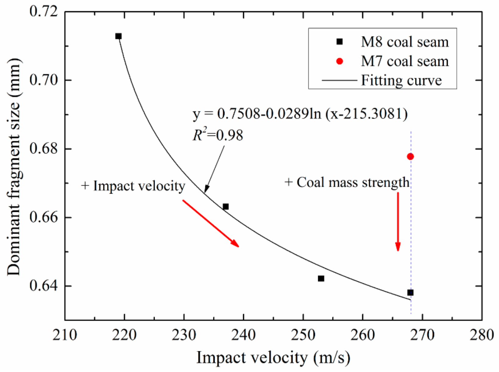
  • The size distributions of coal fragments are mainly determined by the dominant fragment size. The dominant fragment size increases logarithmically as the jet impact velocity decreases; the curves will become flat, and the particle size range is more scattered. With the increase in coal strength, the dominant fragment size increases, but there is no obvious change in the dispersion degree of the fragment size distribution.
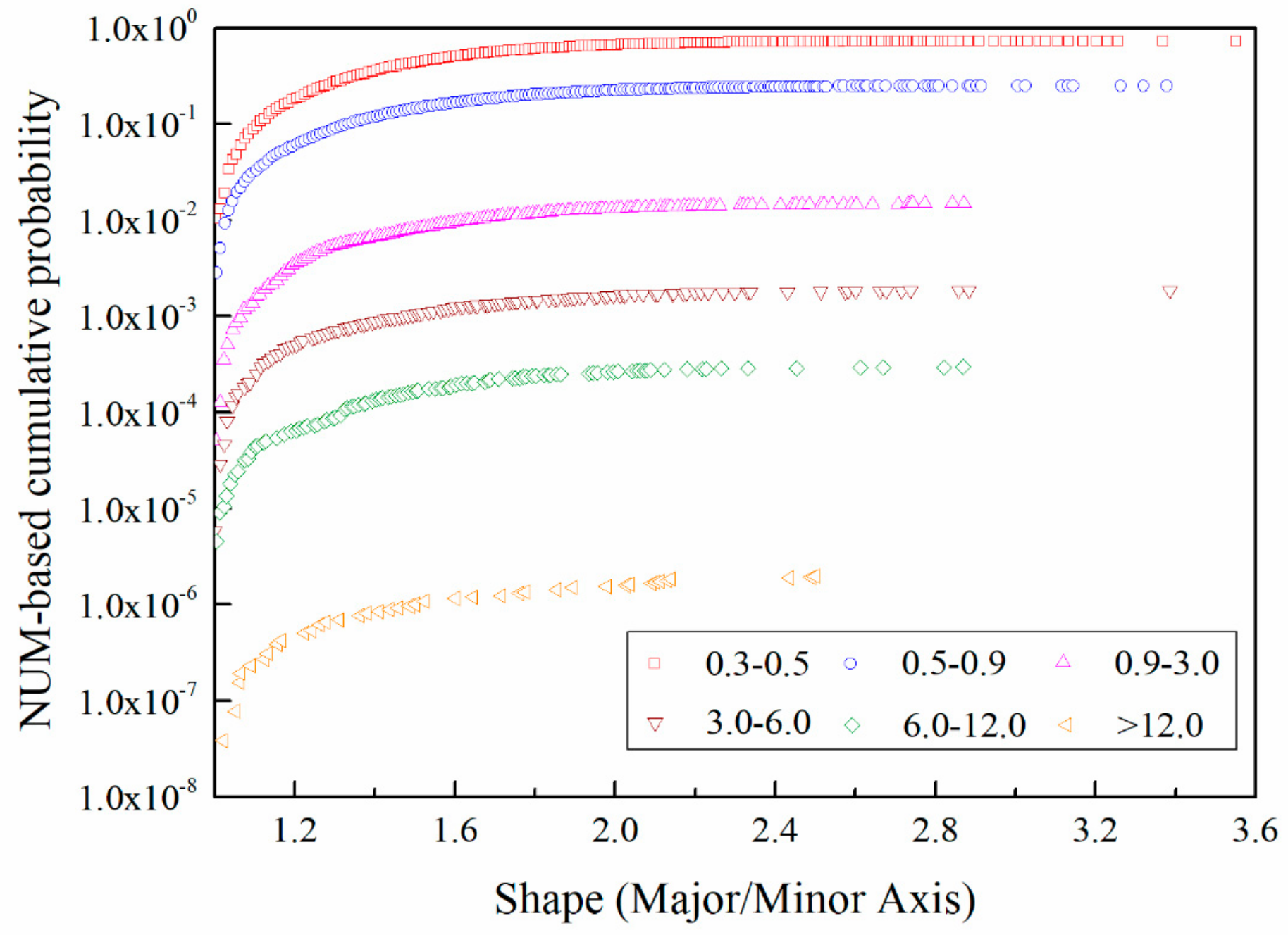
  • The NUM-based cumulative probability curves for the shape (the ratio of the major axis to the minor axis) of coal fragments move toward the upper left with the increase in impact velocity. The curve for high impact velocity attains unity more quickly. Furthermore, there is a difference in the orders of magnitude for the cumulative probability of fragment quantity for different sizes. The larger the particle size is, the smaller its proportion is in all the fragments.
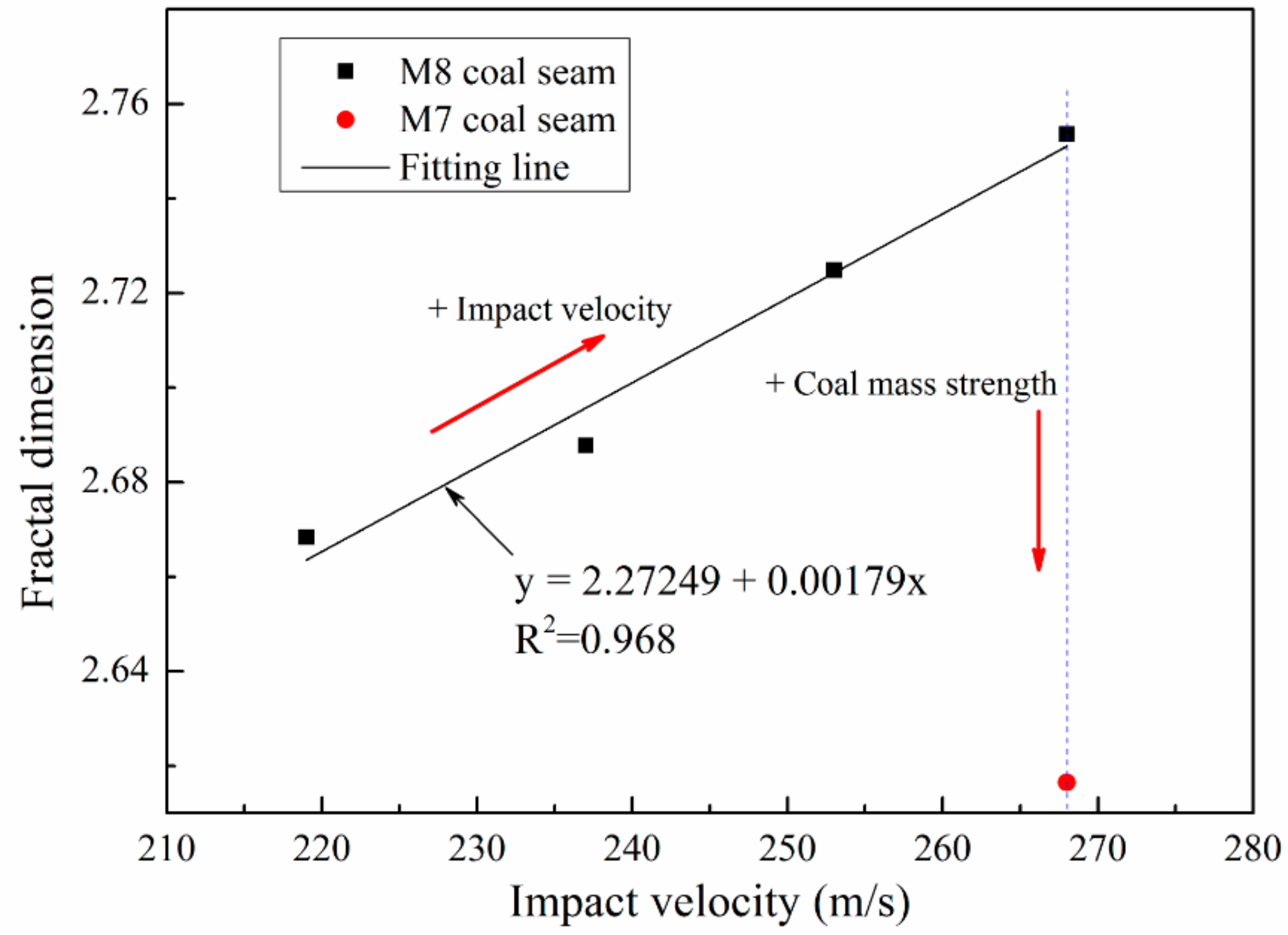
  • The coal fragmentation subjected to water jets in WJD has fractal characteristics. The fractal dimension value increases linearly with the increase in jet impact velocity. The fractal dimension of coal fragments from the M7 coal seam (f = 1.1) is smaller than that from the M8 coal seam (f = 0.5) under the same jet impact energy. In addition, the fractal dimensions obviously increase with the decrease in the dominant fragment size, which can be indirectly used to reflect the dynamic fragmentation of coal.
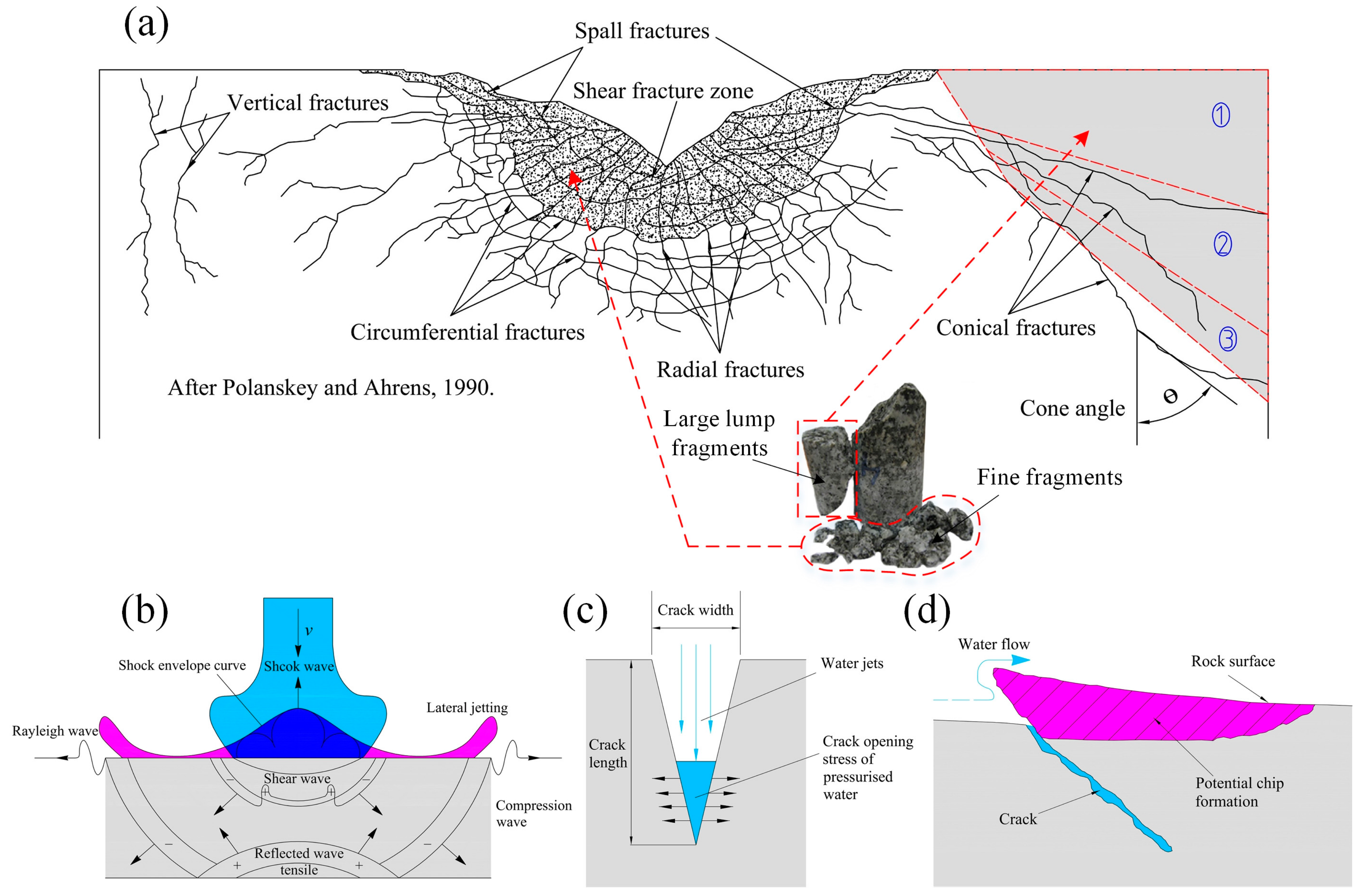
  • The size distribution, morphology and fractal characteristics of coal fragments are determined by the failure patterns of coal subjected to water jet impact. The shear fracture zone, circumferential fractures and radial fractures with a high density and conical fractures are conducive to generating powder particles, fine particles, and large fragments, respectively.

Author Contributions

S.X., Z.G. and Y.L. contributed to conceiving and designing the experiments, analyzing the data, and writing the paper. S.X., Z.Z., Q.L. and L.W. performed the experiments.

Funding

This research was funded by the National Science Fund for Distinguished Young Scholars grant number [51625401]; the National Natural Science Foundation of China grant number [51504046,51774055]; the National Science and Technology Major Projects of China grant number [2016ZX05045] and the Science and Technology Project of Chongqing grant number [cstc2016jcyjA0557].

Acknowledgments

The authors acknowledge the Fengchun coal mine for providing access to the field experimental sites. The authors would like to thank Senior Engineer Jiufu Chen for technical guidance, and the American Journal Experts (AJE) Team (www.aje.com) for editing the English test of a draft of this manuscript.

Conflicts of Interest

The authors declare no conflict of interest.

References

  1. Sun, M.Y. CBM, a nascent new energy. Sci. Technol. Rev. 1996, 8, 59–61. [Google Scholar]
  2. Tang, Z.Q.; Zhai, C.; Zou, Q.L.; Lin, B.Q. Changes to coal pores and fracture development by ultrasonic wave excitation using nuclear magnetic resonance. Fuel 2016, 186, 571–578. [Google Scholar] [CrossRef]
  3. Wang, C.J.; Yang, S.Q.; Yang, D.D.; Li, X.W.; Jiang, C.L. Experimental analysis of the intensity and evolution of coal and gas outbursts. Fuel 2018, 226, 252–262. [Google Scholar] [CrossRef]
  4. Karacan, C.Ö.; Ruiz, F.A.; Cotè, M.; Phipps, S. Coal mine methane: A review of capture and utilization practices with benefits to mining safety and to greenhouse gas reduction. Int. J. Coal. Geol. 2011, 86, 121–156. [Google Scholar] [CrossRef]
  5. Yang, J.; Wu, J.L.; He, T.; Wu, J.H. Energy gases and related carbon emissions in China. Resour. Conserv. Recy. 2016, 113, 140–148. [Google Scholar] [CrossRef]
  6. Lau, H.C.; Li, H.Y.; Huang, S. Challenges and opportunities of coalbed methane development in China. Energy Fuels 2017, 31, 4588–4602. [Google Scholar] [CrossRef]
  7. Li, Q.; Lu, Y.Y.; Ge, Z.L.; Zhou, Z.; Zheng, J.W.; Xiao, S.Q. A new tree-type fracturing method for stimulating coal seam gas reservoirs. Energies 2017, 10, 1388. [Google Scholar] [CrossRef]
  8. Yan, F.Z.; Lin, B.Q.; Xu, J.; Wang, Y.H.; Zhang, X.L.; Peng, S.J. Structural evolution characteristics of middle–high rank coal samples subjected to high-voltage electrical pulse. Energy Fuels 2018, 32, 3263–3271. [Google Scholar] [CrossRef]
  9. Chang, Z.X.; Zhao, Y.S.; Feng, Z.C.; Yang, D. Experimental studies on horizontal drilling hole by water jet in coal seam. Chin. J. Rock Mech. Eng. 2005, 24, 4740–4744. [Google Scholar]
  10. Chi, H.P.; Li, G.S.; Liao, H.L.; Tian, S.Z.; Song, X.Z. Effects of parameters of self-propelled multi-orifice nozzle on drilling capability of water jet drilling technology. Int. J. Rock Mech. Min. Sci. 2016, 86, 23–28. [Google Scholar] [CrossRef]
  11. Dickinson, W.; Anderson, R.R.; Dickinson, R.W. The ultrashort-radius radial system. SPE. Drill. Eng. 1989, 4, 247–254. [Google Scholar] [CrossRef]
  12. Pols, A.C. High-pressure jet-drilling experiments in some hard rocks. J. Press Vessel. Technol. 1977, 99, 353–361. [Google Scholar] [CrossRef]
  13. Pang, B.X.; Wang, S.Y.; Liu, G.D.; Jiang, X.X.; Lu, H.L.; Li, Z.J. Numerical prediction of flow behavior of cuttings carried by Herschel-Bulkley fluids in horizontal well using kinetic theory of granular flow. Powder Technol. 2018, 329, 386–398. [Google Scholar] [CrossRef]
  14. Manjula, E.V.P.J.; Ariyaratne, W.K.H.; Ratnayake, C.; Melaaen, M.C. A review of CFD modelling studies on pneumatic conveying and challenges in modelling offshore drill cuttings transport. Powder Technol. 2016, 305, 782–793. [Google Scholar] [CrossRef]
  15. Adewumi, M.A.; Tian, S.F. Multiphase hydrodynamic analysis of pneumatic transportation of drill cuttings in air drilling. Powder Technol. 1993, 75, 133–144. [Google Scholar] [CrossRef]
  16. Leon, R.; Ramon, J. Fundamental characterization and experimental evaluation of cuttings transport phenomena in horizontal wells. Pol. J. Vet. Sci. 1994, 17, 407–411. [Google Scholar]
  17. Mendoza, R.S.; Gutierrez, A.G. A two-region hydraulic averaging model for cuttings transport during horizontal well drilling. J. Can. Petrol. Technol. 2008, 47, 55–61. [Google Scholar]
  18. Kelessidis, V.C. Flow patterns and minimum suspension velocity for efficient cuttings transport in horizontal and deviated wells in coiled-tubing drilling. Spe. Drill. Completion. 2004, 19, 213–227. [Google Scholar] [CrossRef]
  19. Jiimaa, G. Cutting Transport Models and Parametric Studies in Vertical and Deviated Wells. Master’s Thesis, University of Stavanger, Stavanger, Norway, January 2014. [Google Scholar]
  20. Zakerian, A.; Sarafraz, S.; Tabzar, A.; Hemmati, N.; Shadizadeh, S.R. Numerical modeling and simulation of drilling cutting transport in horizontal wells. J. Pet. Explor. Prod. Technol. 2018, 8, 455–474. [Google Scholar] [CrossRef] [Green Version]
  21. Hou, T.X.; Xu, Q.; Zhou, J.W. Size distribution, morphology and fractal characteristics of brittle rock fragmentations by the impact loading effect. Acta. Mech. 2015, 226, 3623–3637. [Google Scholar] [CrossRef]
  22. Mott, N.F. Fragmentation of shell cases. Proc. R. Soc. Lond. A Math Phys. Sci. 1947, 189, 300–308. [Google Scholar] [CrossRef] [PubMed] [Green Version]
  23. Cheong, Y.S.; Reynolds, G.K.; Salman, A.D.; Hounslow, M.J. Modelling fragment size distribution using two-parameter Weibull equation. Int. J. Miner. Process. 2004, 74, 227–237. [Google Scholar] [CrossRef]
  24. Grady, D.E. Length scales and size distributions in dynamic fragmentation. Int. J. Fract. 2010, 163, 85–99. [Google Scholar] [CrossRef]
  25. Kulatilake, P.H.S.W.; Hudaverdi, T.; Wu, Q. New prediction models for mean particle size in rock blast fragmentation. Geotech. Geol. Eng. 2012, 30, 665–684. [Google Scholar] [CrossRef]
  26. Hogan, J.D.; Rogers, R.J.; Spray, J.G.; Boonsue, S. Dynamic fragmentation of granite for impact energies of 6–28. Eng. Frac. Mec. 2012, 79, 103–125. [Google Scholar] [CrossRef]
  27. Zhong, W.; Yue, F.C.; Ciancio, A. Fractal behavior of particle size distribution in the rare earth tailings crushing process under high stress condition. Appl. Sci. 2018, 8, 1058. [Google Scholar] [CrossRef]
  28. Liu, S.Y.; Du, C.L.; Li, J.P. Fractal character of the distribution law of the cutting coal size. J. China Coal Soc. 2009, 34, 977–982. [Google Scholar]
  29. Wang, F.X.; Wang, R.H.; Zhou, W.D.; Chen, G.C. Numerical simulation and experimental verification of the rock damage field under particle water jet impacting. Int. J. Impact Eng. 2017, 102, 169–179. [Google Scholar] [CrossRef]
  30. Zhou, Q.L.; Li, N.; Chen, X.; Xu, T.M.; Hui, S.E.; Zhang, D. Analysis of water drop erosion on turbine blades on a nonlinear liquid-solid impact model. Int. J. Impact Eng. 2009, 36, 1156–1171. [Google Scholar] [CrossRef]
  31. Liu, W.C.; Kang, Y.; Zhang, M.X.; Zhou, Y.X.; Wang, X.C.; Li, D. Frequency modulation and erosion performance of a self-resonating jet. Appl. Sci. 2017, 7, 932. [Google Scholar]
  32. Chu, H.; Ren, F.; Zheng, Z.; Ming, G.U. Study on granularity distribution of powder by fractal models. Fractals 2017, 25, 1740009. [Google Scholar] [CrossRef]
  33. Xue, Y.Z.; Si, H.; Xu, D.Y.; Yang, Z.L. Experiments on the microscopic damage of coal induced by pure water jets and abrasive water jets. Powder Technol. 2018, 332, 139–149. [Google Scholar] [CrossRef]
  34. Huang, F.; Lu, Y.Y.; Liu, X.C.; Ao, X.; Li, L.W. Breakage mechanism of transverse isotropic rock subjected to high-pressure water jet. Chin. J. Rock. Mech Eng. 2014, 33, 1329–1335. [Google Scholar]
  35. Ragab, A.M.S. Improving well productivity in an Egyptian oil field using radial drilling technique. J. Pet. Gas Eng. 2013, 4, 103–117. [Google Scholar]
  36. Lu, Y.Y.; Xiao, S.Q.; Ge, Z.L.; Zhou, Z.; Deng, K. Rock-breaking properties of multi-nozzle bits for tree-type drilling in underground coal mines. Energies 2016, 9, 249. [Google Scholar] [CrossRef]
  37. Lu, Y.Y.; Zhou, Z.; Ge, Z.L.; Zhang, X.W.; Li, Q. Research on and design of a self-propelled nozzle for the tree-type drilling technique in underground coal mines. Energies 2015, 8, 14260–14271. [Google Scholar] [CrossRef]
  38. Beirlant, J.; Matthys, G. Generalized extreme value distribution; John Wiley & Sons Ltd.: New York, NY, USA, 2006. [Google Scholar]
  39. Levy, S.; Molinari, J.F. Dynamic fragmentation of ceramics, signature of defects and scaling of fragment sizes. J. Mech. Phys. Solids. 2010, 58, 12–26. [Google Scholar] [CrossRef] [Green Version]
  40. Wang, H.; Ramesh, K.T. Dynamic strength and fragmentation of hot-pressed silicon carbide under uniaxial compression. Acta. Mater. 2004, 52, 355–367. [Google Scholar] [CrossRef]
  41. Taghipour, A.; Lund, B.; Ytrehus, J.D.; Skalle, P. Experimental study of hydraulics and cuttings transport in circular and noncircular wellbores. J. Energy Resour. Technol. 2013, 136, 022904. [Google Scholar] [CrossRef]
  42. Dlouhý, I.; Strnadel, B. The effect of crack propagation mechanism on the fractal dimension of fracture surfaces in steels. Eng. Fract. Mech. 2008, 75, 726–738. [Google Scholar] [CrossRef]
  43. Zhao, Y.X.; Gong, S.; Zhang, C.G.; Zhang, Z.N.; Jiang, Y.D. Fractal characteristics of crack propagation in coal under impact loading. Fractals 2018, 26, 1840014. [Google Scholar] [CrossRef]
  44. Zhang, W.Q.; Shi, B.M.; Mu, C.M. Experimental research on failure and energy dissipation law of coal under impact load. J. Min. Saf. Eng. 2016, 33, 375–380. [Google Scholar]
  45. He, M.C.; Yang, G.X.; Miao, J.L.; Jia, X.N.; Jiang, T.T. Classification and research methods of rockburst experimental fragments. Chin. J. Rock Mech. 2009, 28, 1521–1529. [Google Scholar]
  46. Hu, L.Q.; Li, X.B. Study on energy consumption in fracture and damage of rock induced by impact loadings. Chin. J. Rock Mech. 2002, 21, 2304–2308. [Google Scholar]
  47. Bagde, M.N.; Raina, A.K. Chakraborty AK. Rock mass characterization by fractal dimension. Eng. Geol. 2002, 63, 141–155. [Google Scholar] [CrossRef]
  48. Wang, L.; Gao, Q. Fragmentation distribution prediction of rock based on damage energy dissipation. Chin. J. Rock Mech. 2007, 26, 1202–1211. [Google Scholar]
  49. Mandelbrot, B.B. The Fractal Geometry of Nature; W. H. Freeman: New York, NY, USA, 1982; pp. 245–256. [Google Scholar]
  50. Tyler, S.W.; Wheatacraft, S.W. Fractal scaling of soil particle-size distributions: Analysis and limitations. Soil Sci. Soc. Am. J. 1992, 56, 362–369. [Google Scholar] [CrossRef]
  51. Ping, C.; Li, J.T.; Yuan, H.P. Testing study of subcritical crack growth rate and fracture toughness in different rocks. Trans. Nonferrous Met. Soc. China 2006, 16, 709–713. [Google Scholar]
  52. Lu, Y.Y.; Huang, F.; Liu, X.C.; Ao, X. On the failure pattern of sandstone impacted by high-velocity water jet. Int. J. Impact Eng. 2015, 76, 67–74. [Google Scholar] [CrossRef]
  53. Polanskey, C.A.; Ahrens, T.J. Impact spallation experiments: fracture patterns and spall velocities. Icarus. 1990, 87, 140–155. [Google Scholar] [CrossRef]
  54. Dehkhoda, S.; Hood, M. An experimental study of surface and sub-surface damage in pulsed water-jet breakage of rocks. Int. J. Rock Mech. Min. Sci. 2013, 63, 138–147. [Google Scholar] [CrossRef]
  55. Field, J.E. ELSI conference: Invited lecture: Liquid impact: theory, experiment, applications. Wear 1999, 233–235, 1–12. [Google Scholar] [CrossRef]
  56. Huang, F. On the Transient Dynamics of Water Jet Impinging Target and the Mechanism of Water Jet Breaking Rock. Ph.D. Thesis, Chongqing University, Chongqing, China, 2015; p. 96. [Google Scholar]
Figure 1. Schematic of WJD system in underground coal mine.
Applsci 08 01988 g001
Figure 2. Water-jet bits used in field experiment: (a) schematic diagram of nozzle layout in the water-jet bit, and (b) physical image of the bits.
Applsci 08 01988 g002
Figure 3. Field experimental site of WJD at the Fengchun coal mine: (a) Field experimental site of WJD and the geological histogram at the +300N1 rock crosscut; (b) Sketch map of field experimental site; (c) Target coal seams for WJD.
Applsci 08 01988 g003
Figure 4. Determination of fragment size and shape distributions using the image processing method. (a) Coal fragment photographs of each size degree, and (b) binary images.
Applsci 08 01988 g004
Figure 5. Minimum enclosing rectangles of coal fragments with different particle sizes: (a) 6.0–12.0 mm, and (b) >12.0 mm.
Applsci 08 01988 g005
Figure 6. Fitting curves of the cumulative probability of coal fragments based on the GEV distribution function and Weibull distribution function (impact velocity = 253 m/s). (a) The fitting curves of all the particle sizes, (b) and (c) is the partial magnification of fitting curves for the large and small particle sizes, respectively.
Applsci 08 01988 g006
Figure 7. Experimental data of NUM-based cumulative probability for the equivalent diameter of coal fragments and fitted curves. (a) Size distributions of coal fragments under different jet impact velocities in the M8 coal seam. (b) Fragment size distributions of the various coal seams under a jet velocity of 268 m/s each.
Applsci 08 01988 g007
Figure 8. Distribution density of the equivalent diameter of coal fragments for various jet velocities and coal mass strengths. (a) Different jet velocities in the M8 coal seam. (b) Different strengths of coal seams at the same jet velocity of 268 m/s.
Applsci 08 01988 g008
Figure 9. Relationship between the dominant fragment size and the jet impact velocity.
Applsci 08 01988 g009
Figure 10. NUM-based cumulative probability for the shape of coal fragments. (a) Shape distributions of coal fragments under different jet impact velocities in the M8 coal seam. (b) Shape distributions of the various coal seams under the same jet velocity of 268 m/s.
Applsci 08 01988 g010
Figure 11. NUM-based cumulative probability for the shape of coal fragments at different sizes.
Applsci 08 01988 g011
Figure 12. Diagrams of the relative mass versus the relative fragment size for coal fragments generated from WJD holes in coal seams: (a) M8 coal seam and (b) M7 and M8 coal seams for an impact velocity of 268 m/s.
Applsci 08 01988 g012
Figure 13. Relationship of the fractal dimension and jet impact velocity.
Applsci 08 01988 g013
Figure 14. (a) Different failure patterns observed inside the rock samples and the failure mechanisms of rock under water jet impact: (b) shock stress wave effect, (c) pressured water wedge effect, and (d) water flow scouring effect [52,53,54,55].
Applsci 08 01988 g014
Figure 15. Schematic diagram of cleats and fracture structure in coal and rock mass.
Applsci 08 01988 g015
Table 1. Occurrence conditions and properties of coal seams at +300N1 rock crosscut.
Coal SeamProtodyakonov CoefficientOriginal Gas Content (m3/t)Coal Seam Thickness (m)Coal Seam Angle (°)
M71.1015.720.7546
M80.5016.723.0946
Table 2. Mass percentage of the particles with the sizes less than 0.3 mm.
No.78-18-28-38-4
Impact velocity (m/s)268219237253268
Mass percentage16%21%25%29%32%
Table 3. Sieving results of the coal fragments under water jet impact in different WJD holes.
No.Impact Velocity (m/s)Fragment Mass (g)Maximum Particle Size (mm)
≤0.3 mm0.3–0.5 mm0.5–1 mm1–3 mm3–6 mm6–12 mm>12 mm
72689033038831106137087227650.36
8-121916314027232179955132443948.13
8-22372297375129924851109140520439.47
8-32532950404194522651141138617041.17
8-42683490570235419361150135521642.59
Table 4. Relationship between the fractal dimension and dominant fragment size.
Impact Velocity (m/s)Fractal DimensionDominant Fragment Size
2192.66840.7129
2372.68780.6632
2532.72480.6422
2682.75360.6381

