Residual Stress in Laser Welding of TC4 Titanium Alloy Based on Ultrasonic laser Technology


1
College of Sciences, Northeastern University, Shenyang 110819, China
2
Key Laboratory for Anisotropy and Texture of Materials Ministry of Education, Northeastern University, Shenyang 110819, China
*
Author to whom correspondence should be addressed.
Appl. Sci. 2018, 8(10), 1997; https://0-doi-org.brum.beds.ac.uk/10.3390/app8101997
Submission received: 3 September 2018
/
Revised: 8 October 2018
/
Accepted: 8 October 2018
/
Published: 20 October 2018
(This article belongs to the Special Issue Laser Ultrasonics)
Abstract
:Laser welding is widely used in titanium alloy welding due to its high energy density, small heat affected zone, and rapid processing ability. However, problems with laser welding, such as deformation and cracking caused by residual stress, need to be resolved. In this paper, the residual stress in laser welding of TC4 titanium alloy was studied using an ultrasonic laser. The residual stress in titanium alloy plates is considered a plane stress state. A pre-stress loading method is proposed and acoustoelastic coefficients are obtained. Based on the known acoustoelastic coefficients, the transverse and longitudinal residual stresses in laser welding are measured using an ultrasonic laser. The results show that longitudinal residual stress is greater than the transverse stress. The distribution regularity of the residual stress is similar to normal welding, but the tensile stress zone is much narrower. Then, the influence of heat input and welding speed on residual stress is discussed. With increasing heat input, the welding zone widens, and the peak value of the residual stress increases. A higher welding speed should be chosen when the welding power is constant. This research has important significance for the measurement and control of residual stress in the laser welding process.
1. Introduction
The high temperature mechanical properties, high strength-to-weight ratio, and good corrosion resistance of titanium and titanium alloys have led its diversified and successful application in a variety of fields with demanding performance and reliability requirements, such as in the aerospace, automotive, medical, nuclear, petrochemical, and power generation industries [1,2]. Common titanium alloy welding methods include tungsten inert gas welding, electron beam welding, and laser welding. Laser welding is a dominant welding method because of its concentrated energy density, small heat affected zone (HAZ), minimal welding deformation, and fast welding speed. Laser welding technology is suitable for welding of TC4 titanium alloy [3,4]. During laser welding, residual stress inevitably results from uneven and fast heating and cooling, affecting the safety performance of welded structures. However, due to the constraints of available testing technology and methods, the formation mechanism of the residual stress in laser welding has not yet been effectively solved. The traditional methods of measuring residual stress include cutting groove, hole-drilling, and X-ray [5,6,7]. However, the mechanical method is time-consuming, complex, and can damage materials. The X-ray method involves controlled measurement and the chance of damaging human health is low. Ultrasonic lasers are advantageous because they are highly precise, non-contact, nondestructive, and highly adaptable. The technology is especially suitable for nondestructive testing of materials with complex curved surfaces, even in harsh environments. Ultrasonic laser technology has been widely used in defect detection [8,9] and residual stress measurement [10,11,12,13].
Many researchers have been attracted by ultrasonic laser technology because of its outstanding advantages in residual stress measurement. Duquennoy et al. [10] measured surface residual stress in steel bars with different heat treatments processes using a laser-induced ultrasonic surface wave. Ruiz and Nagy [11] discussed surface wave dispersion produced by residual stress. The results showed that diffraction correction can be introduced to improve the precision of surface wave dispersion measurements. Based on the laser ablation mechanism, Bescond et al. [12] measured residual stress using the surface skimming longitudinal waves generated by a laser. Although the method damaged the sample surface, the measurement precision was high. Doxbeck et al. [13] determined the residual stress in autofrettaged steel specimens using laser-generated creeping longitudinal waves. Moreau and Man [14] measured the residual stress in a 7075-T651 aluminum sample surface-treated with low plasticity burnishing using an ultrasonic laser. Dong et al. [15] used laser-induced surface waves to determine the velocity distribution around the laser welded joint of an aluminum alloy sheet, from which the profile of the principal residual stress was calculated based on acoustoelastic theory. Karabutov et al. [16] designed a special optoacoustic transducer for ultrasonic pulse excitation and detection. The technology was applied to the residual stress measurement of electronic welded stainless steel specimens. The results were consistent with conventional approaches. The simplified finite element model (FEM) was used by Sanderson and Shen [17] to determine the sensitivity and capability of ultrasonic laser technology for residual stress measurement. The possibility of depth profiling was demonstrated for depths below the surface up to 0.3 mm for the particular case studied. Many scholars have researched laser welding and heat treatments for stress relaxation after welding. Fernandes et al. [18] used the laser Nd:YAG (Neodymium Yttrium Aluminum Garnet) welding machine to determine the optimal welding parameters of dual-phase steel, and heat treatment was used to reduce the hardness of the HAZ. Liao et al. [19] researched the effects of laser welding parameters on penetration and microstructure characterization of a DP1000 steel butt joint. The results indicated that the process parameters have a significant effect on the weld penetration, and the fusion zone of the butt joints exhibited greater hardness than the base metal and HAZ of butt joints. Li et al. [20] investigated the weldability during 10 kW high-power fiber laser welding of 304 stainless steel with three kinds of shielding gases. The appropriate shielding gas should be selected according to the application demands and welding requirements. Popescu et al. [21] reported a feedback mechanism for rapid identification of optimal laser parameters during welding of AlMg5 coupons using real-time monitoring by high-speed imaging. The optimization of the Nd:YAG laser welding process parameters for sealed small titanium tube ends was presented by Lee et al. [22]. The effects of the laser welding parameters on the melted length were analyzed and optimized using the Taguchi and regression analysis method.
In this paper, ultrasonic laser technology, a noncontact method using laser for the generation and detection of ultrasonic waves, is used to measure residual stress in laser welding of TC4 titanium alloy. The technology is based on determining the small ultrasonic wave velocity change caused by stress. The residual stress of a TC4 titanium alloy plate is simplified to plane stress state. A method of pre-stress loading is proposed and the acoustoelastic coefficients are obtained. The residual stress distribution measured is compared with the results of strain gauge measurements. Then, the influence of heat input, welding speed, and heat treatment on residual stress is discussed. The results show that the effect of heat input on residual stress is significant. With increasing heat input, the peak value of residual stress increases. When the welding power is constant, faster welding speeds are preferred. Heat treatment can reduce the residual stress to a certain extent, but it is still necessary to control the residual stress by optimizing the welding process parameters. The contribution of this paper is important for the optimization of laser welding parameters and the evaluation of residual stress.
2. Theoretical Basis
The main effect of stress on the propagation of ultrasonic waves in a material is the variation in wave velocity of propagation [23]. Another effect, to a lesser extent, is the variation in the amplitude of the ultrasonic wave, which can be specified according to their attenuation [24]. Generally, the relative change in the velocity caused by stress is proportional to the latter, and the proportional coefficient is a parameter dependent on the material, which is called the acoustoelastic coefficient [25]. When the stress is located near the surface, rather than having the wave propagating through the thickness of the material, the energy of the wave can be directed along the surface between the transmitter and the receiver. Among waves that propagate near the surface, the surface wave is particularly attractive because it propagates without radiation loss and the energy is concentrated within a layer of about one wavelength thickness under the surface. Some studies have shown the sensitivity of these waves to stress in different materials [26,27]. Since the depth of penetration of the surface wave into the solid is approximately one wavelength, it is possible to measure stress gradients using surface waves at different frequencies [28]. The first theory of surface waves in elastic materials with homogeneous deformation was developed by Hayes and Rivlin for waves propagating along one of the principal axes of stress [29]. The acoustoelastic theory effect for ultrasonic surface wave was reviewed in Pao et al. [30]. Only the final results are provided here. Considering the study of the laser welding residual stress of an isotropic and uniform sheet, compared with the other two directions, the stress along the thickness direction was very small. We approximated σz = 0 and the model can be simplified to the plane stress state. In this paper, the surface wave propagation on the free surface of an elastic and isotropic media defined by normal plane coordinates (x,y) is considered. Based on the discussion of the acoustoelastic effect of surface wave conducted by Husson [31], when the displacement caused by the surface wave propagation is infinite, the relative change in the propagation velocity can be expressed as a function of two nonzero surface stresses, and , as follows:
where is the velocity of the surface acoustic wave with no residual stress present; and are the surface wave velocities in the presence of () in the and directions, respectively; and are the principal stresses; and and are the acoustoelastic coefficients of the surface ultrasonic wave that depend on not only the stress direction but also on the propagation direction of the wave.
The acoustoelastic coefficients can be evaluated according to the mechanical parameters of the material [32]. Considering the difference between experiment and theory, in order to enhance the measurement precision, a pre-stress loading method is proposed to calibrate the coefficients in the experiment. To achieve stress inversion, the coefficients must be determined in advance. For uniaxial tensile stress fields, only the pre-stress is applied; the coefficients can be obtained from the calibration experiment. When the sample is in a uniaxial stress state, Equations (1) and (2) can be simplified as follows, respectively:
This stage of calibration involves applying different loads on a sample and measuring the corresponding acoustic wave velocities. The experimental results confirmed the linear evolution of the relative variation of the velocity as a function of the load, and the slope directly corresponds to the acoustoelastic coefficients. From Equations (3) and (4), for a definite pre-stress, if the surface wave propagation velocity along the and directions is measured, we obtain the acoustoelastic coefficients , respectively.
3. Experimental Process
The experimental process was divided into three parts: preparation of specimens with continuous laser welding, using ultrasonic laser technology for measurement of the residual stress in laser welding, and hole-drilling to verify the experimental results.
3.1. Preparation of Experimental Specimens
To ensure welding quality, preparatory work is necessary. The national standard GB/T3621 was applied, and anything beyond standard scratches, indentation, dents, and cracks were not allowed on the surface of the sample. The sample should be treated before welding and the treatment solution composition was HNO3 (30%–40%), HF (3%), and water (the rest). The temperature of the treatment solution was 20–30 °C, and the treatment time was . Then, the sample was flushed with cold water for 3 min, and dried in a drying box at . Sandpaper was used to polish the oxide layer on the surface to be welded of the sample. Until the sample surface is polished into silver white metallic luster, acetone is used to wipe it clean. Laser welding is a high precision welding method, so there are certain requirements for the working environment. The room temperature should be kept at , and the relative humidity should not exceed 60%. The voltage fluctuation of the welding power supply should be less than 10% to ensure the stability of the laser. In order to ensure the stability of the specimens in the welding process, a special fixture should be used to fix the specimens. On the back of the fixture, a protective gas passage should be reserved to prevent the back of the weld from being oxidized. The laser welding equipment used in the experiment was a HL3006D-type HAAS-LASER YAG laser produced by TRUMPF (Stuttgart, Germany). The highest stable output power was 3 kW, the wavelength was , and the diameter of the spot after focusing was 0.6 mm. The light guiding and focusing system was composed of a circular polarizer, a beam expander, an optical fiber, and a focusing lens. In the process of welding, the six axis manipulator produced by KHI (Kawasaki, Japan) was used for precise positioning, and the relative motion of the laser beam and work piece was realized using an operating platform. Many parameter settings can be changed during laser welding, such as welding power, welding speed, welding angle, heat input, and inert gas flow, but in most cases, the individual effect on the residual stress was not clear. Since the relationship between the process parameters in laser welding is complex, in this paper, only welding power, welding speed, and heat input were changed. The material was a TC4 titanium alloy plate with a yield strength of 860 , a density if , an elastic modulus of , and a Poisson ratio of 0.34. The nominal chemical composition of the alloy is shown in Table 1.
Continuous laser welding was used in this experiment. The weldment size was and the welding method was butt welding. Argon was used as a protective gas. The protective gas was composed of three parts: the coaxial protective gas for protecting the melting pool, the front protective gas (for protecting the surface of the newly solidified weld, and the back protective gas for protecting the back of the weld. Considering the use of laser energy, the defocusing amount was set to zero. The range of welding power and welding speed was chosen as wide as possible while ensuring the welding quality of the products. Table 2 shows the different combinations of welding speed and welding power used in this paper. Heat input is defined as welding power/welding speed. The heat input represents the laser energy absorbed by the weld per unit length, and it plays a decisive role in the distribution in welding residual stress. Based on the preliminary process exploration, the main parameters selected in this experiment are shown in Table 2, and nine experimental specimens were prepared for further discussion on laser welding residual stress.
3.2. Ultrasonic laser for Measurement of Residual Stress in Laser Welding
3.2.1. Experimental Device
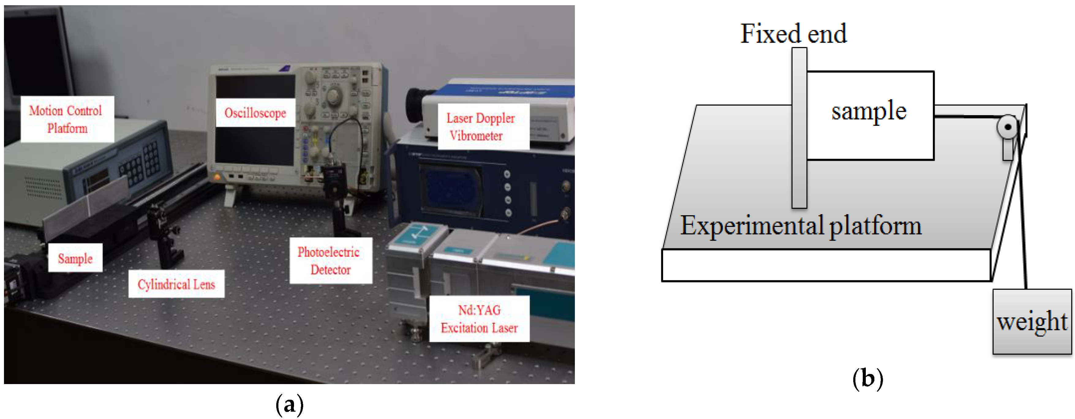
The whole ultrasonic laser experiment system included three sections: a Nd:YAG laser was used to generate the ultrasonic waves, a laser Doppler vibrometer was used to detect ultrasonic waves, a the pre-stress loading setup was used to calibrate the acoustoelastic coefficients. The whole system is presented in Figure 1. A laser pulse with a Gaussian profile was sent by the Nd:YAG laser setup (Dawa-100, Beamtech Optronics Ltd., Beijing, China), the beam was focused by the cylindrical lens as a line source with a 0.6 mm width and a 20 mm length to generate the surface waves. The main parameters of the generation laser were as follows: wavelength pulse width single pulse energy , and the maximum repetition frequency was adjustable within 0–20 Hz. The vibration information was detected by a laser Doppler vibrometer (Sdptop LV-S01, Sunny Optical Technology Ltd., Suzhou, China), with a He-Ne laser wavelength of 632.8 nm, frequency band of 2.5 MHz, work distance of 0.35–20 m, and a displacement resolution of 0.008 nm. The laser Doppler vibrometer had auto-focus/long-distance focus and focus point storage functions. The He-Ne laser can be manually fine-tuned by rotating the lens of the vibrometer. The detection laser was focused into a light spot with a diameter of 0.7 mm. Few laser beams are received by the photoelectric detector (Thorlabs Det10A/M, Thorlabs Inc., Newton, NJ, USA) with a wavelength of 200–1100 nm. It achieves perfect synchronization of the oscilloscope with the laser shots. An oscilloscope (Dpo4102, Tektronix Inc., Beaverton, OR, USA), with a sampling rate of 5 GS/s and frequency band of 1 GHz, was employed to store the output electrical signal from the photoelectric detector and the Doppler vibrometer after 64 repetitions, on average, in order to reduce random noise. The computer analyzed and processed the data from the photoelectric detector and oscilloscope. In the measurement experiment, two methods were adopted to avoid the interaction between the various modes of the ultrasonic signals. First, the signal detecting location was far from the exciting location. Because the propagation velocities of various waves are different in the media, sufficient distance can separate the different ultrasonic waves to better identify the transverse and longitudinal waves. In addition, the laser Doppler vibrometer has two functional options with a low-pass filter (OUTPUT LP FILTER: 500 Hz, 5 kHz, 20 kHz, and 100 kHz) and a high-pass filter (OUTPUT HP FILTER: DC is namely direct current, DC Block, 60 Hz, 1 kHz). The high-pass filter function was used, as it removes unnecessary interference signals in low frequency. OUTPUT HP FILTER: 1 kHz was set, and a high frequency wave of 1–2.5 MHz was received.
3.2.2. Determination of Acoustoelastic Coefficients
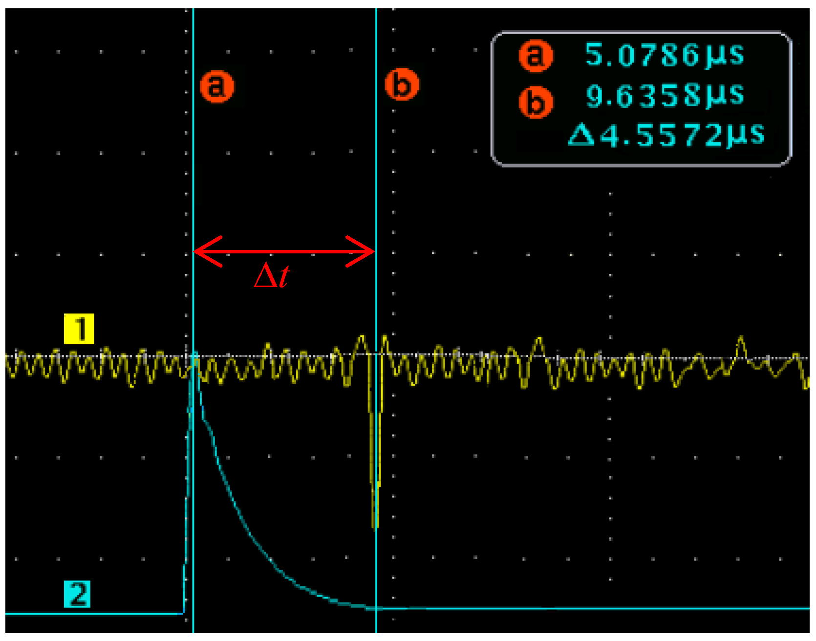
To measure residual stress with an ultrasonic laser, we first performed a calibration experiment, and the acoustoelastic coefficients of the material were obtained. The acoustoelastic coefficients were obtained via online pre-stress loading. One end of the TC4 base material specimen was fixed to the optical platform (Thorlabs Nexus, Thorlabs Inc., Newton, NJ, USA) with bolts. The constraints were considered as fixed boundary conditions. The other end of the specimen was connected with a weight using a cable, and the different tension stresses were achieved by changing the weight. Based on the Saint Venant principle, the tensile stress field with uniform distribution was obtained far from the loading zone. Firstly, the velocity of surface wave was measured in the base material specimen without loading. Then, the specimens under uniform tensile stress were measured. Notably, the loading stress should be less than the yield strength of the TC4 base material to avoid plastic deformation. The velocities, and , were determined parallel and perpendicular to the principal stress direction, respectively. In the two cases, the velocities were measured using the same experimental program. The ultrasonic wave velocity was determined by travel time and distance. The travel time was recorded with an oscilloscope, and the results are presented in Figure 2. The distance between the excitation location and the detecting location was measured with a Vernier caliper.
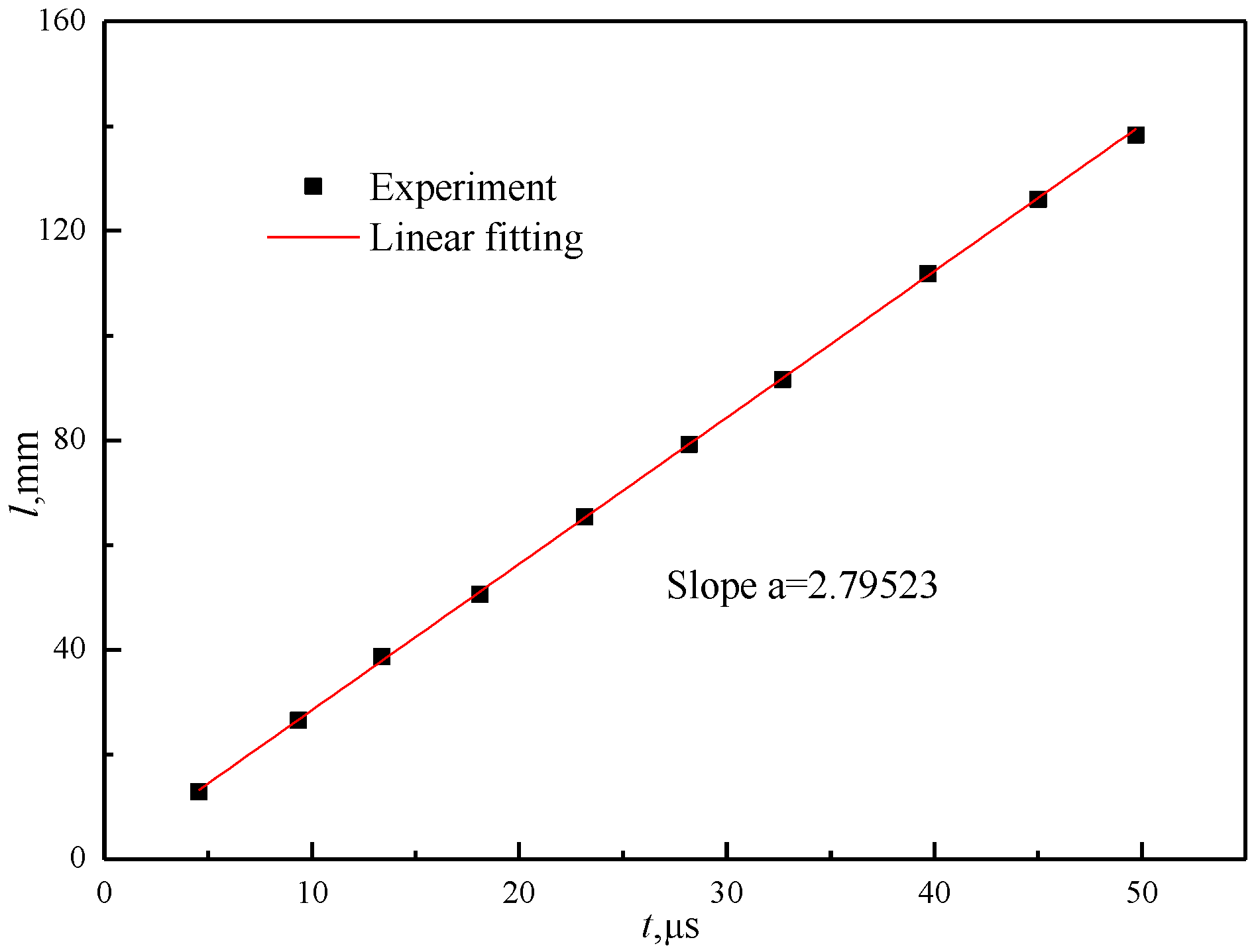
Two channels of the oscilloscope were used in the experiment. The yellow curve record the ultrasonic vibration signal from the laser Doppler vibrometer. The surface wave signal was obvious, which satisfies the surface wave characteristics. The blue curve recorded the synchronous time reference signal from the photoelectric detector. The travel time between the excitation location and the detection location was determined by the cursor. The measurement error of the ultrasonic wave propagation time and distance was solved using a linear fitting experiment. The slope of the linear fitting curve is , where is the velocity of the surface wave, as shown in Figure 3.
The pulsed laser acting on the surface of a material produces ultrasonic longitudinal waves, shear waves, and surface waves. The propagation velocities of these waves are related to the density and elastic constants of the material [33]. According to solid mechanics theory [34], the equations can be expressed as:
where and are the shear wave velocity and surface wave velocity, respectively; is the elastic modulus; is the Poisson ratio; and is the density of the TC4. The theoretical solution of surface waves velocity can be obtained using Equations (5) and (6). The error of the theoretical and experimental results was 1.1%.
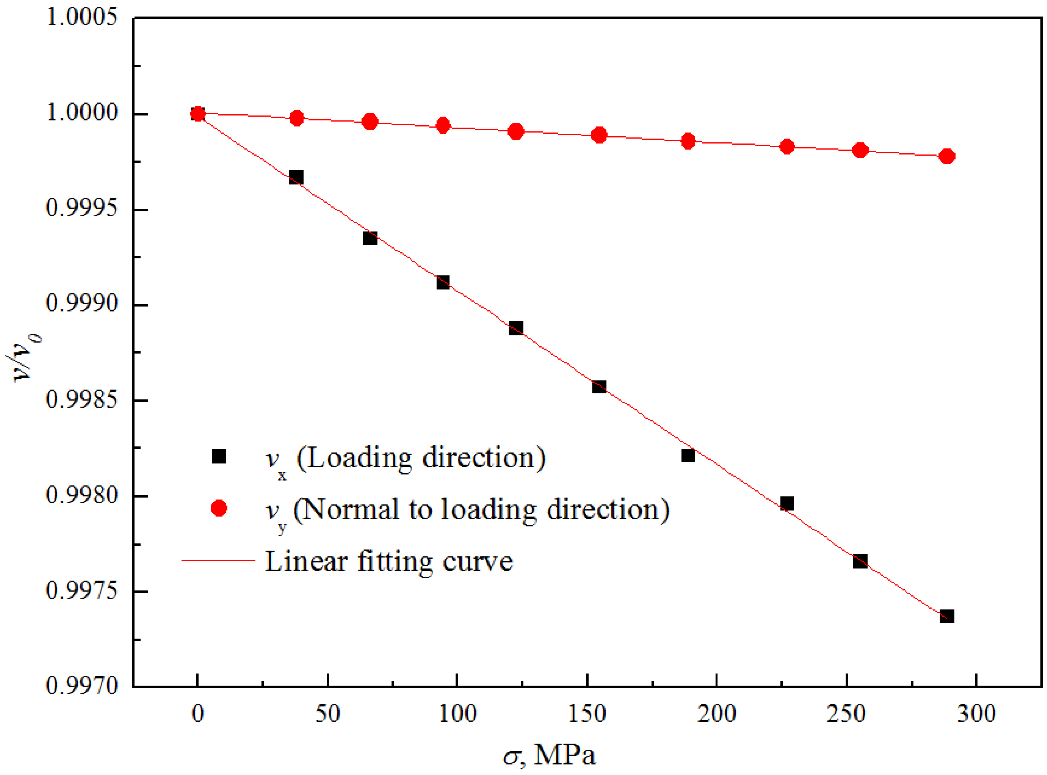
Then, different stress fields were applied to the specimen via pre-stress loading. At each uniaxial tensile loading stage, the propagation velocity of the surface wave, perpendicular and parallel to the loading direction, was measured. By step-by-step loading of the TC4 specimen, the relationship between surface wave velocity ratio and tensile stress are represented by the curves. The slopes represent the coefficient of the TC4 material, as shown in Figure 4. For the surface waves in the TC4 material, we determined and . For most of the materials researched, was a clear conclusion reported in Ya et al. [35]. Once the acoustoelastic coefficients were determined via online pre-stress loading, the residual stress was evaluated using Equations (1) and (2).
3.2.3. Measurement of Residual Stress
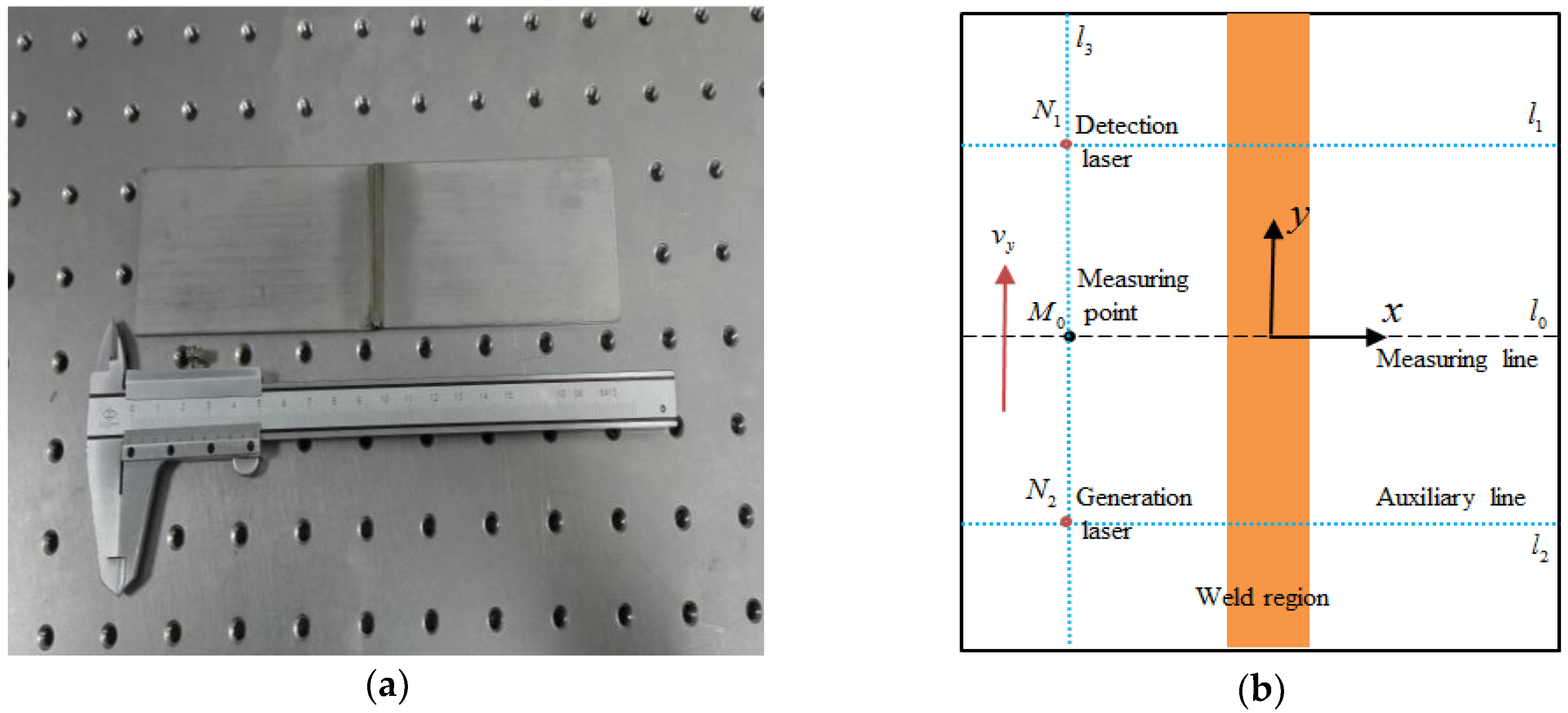
The residual stress during the laser welding of TC4 titanium alloy was measured using ultrasonic laser technology. The experimental program and the location of the measurement lines are shown in Figure 5, where is the measurement point, and all the measurement points are arranged in the measuring line; and are the location of the excitation laser and detection laser, respectively; is the measurement line (black line) arranged on the center axis of the specimen; and , and are the auxiliary lines (blue line). Notably, the stress at the measuring point is actually the average residual stress within the travel distance of the surface wave. Therefore, when there is a large stress gradient or stress concentration, the distance between the measurement points must be refined to improve the measuring accuracy. The transverse propagation velocity was obtained using the same experimental program, and the residual stress of measurement point was determined using Equations (1) and (2).
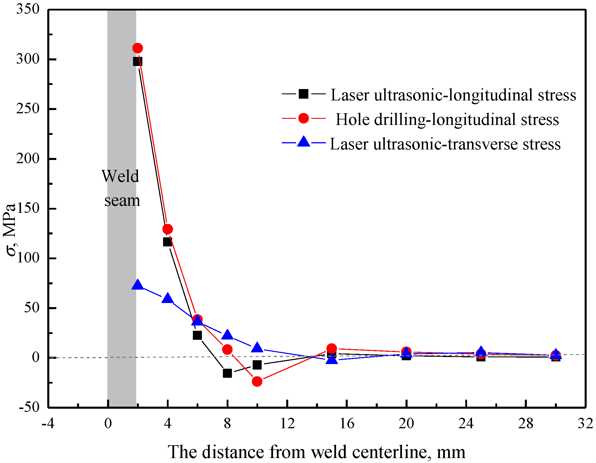
Figure 6 shows the residual stress distribution of weld 1 with a welding power of 2800 W, welding speed of 6.0 m/min, and heat input of 28 kJ/m. Since the boundary conditions at both ends of the weld centerline were similar, a symmetric approach was assumed in the residual stress profile. It was reasonable to assume that data points at the same distance but at either sides of the centerline would have the same value of residual stress. These types of symmetric approaches were adopted in a number of research studies on welds [3,4]. The longitudinal residual stress was greater than the transverse residual stress. The longitudinal residual stress was high tensile stress near the welding seam, and the maximum values of longitudinal and transverse residual stresses were 297.7 MPa and 72.4 MPa near the HAZ, respectively. The longitudinal stress decreased rapidly with increasing distance from the weld centerline, passing through zero at a distance near to the weld centerline and leading to the balancing of the compressive stress at approximately −15.7 MPa in the far field. The welding residual stress reached one-third of the yield strength of the material. If residual stress is superimposed with external forces, it easily exceeds the yield strength, resulting in plastic deformation and failure of the components. The longitudinal residual stresses measured by the hole-drilling method and ultrasonic laser method were basically the same. However, error and uncertainty in measurement are inevitable. For the hole-drilling technique, the stress uncertainty mainly depends on the absolute value of the strain. For the ultrasonic laser technique, the uncertainty mainly depends on the propagation velocity of the ultrasonic waves. Considering the maximum longitudinal residual stress, corresponding to the ultrasonic laser and hole-drilling techniques, the uncertainty of measurements were 1.2 MPa and 2.4 MPa, respectively.
3.3. Hole-Drilling for Measurement of Residual Stress
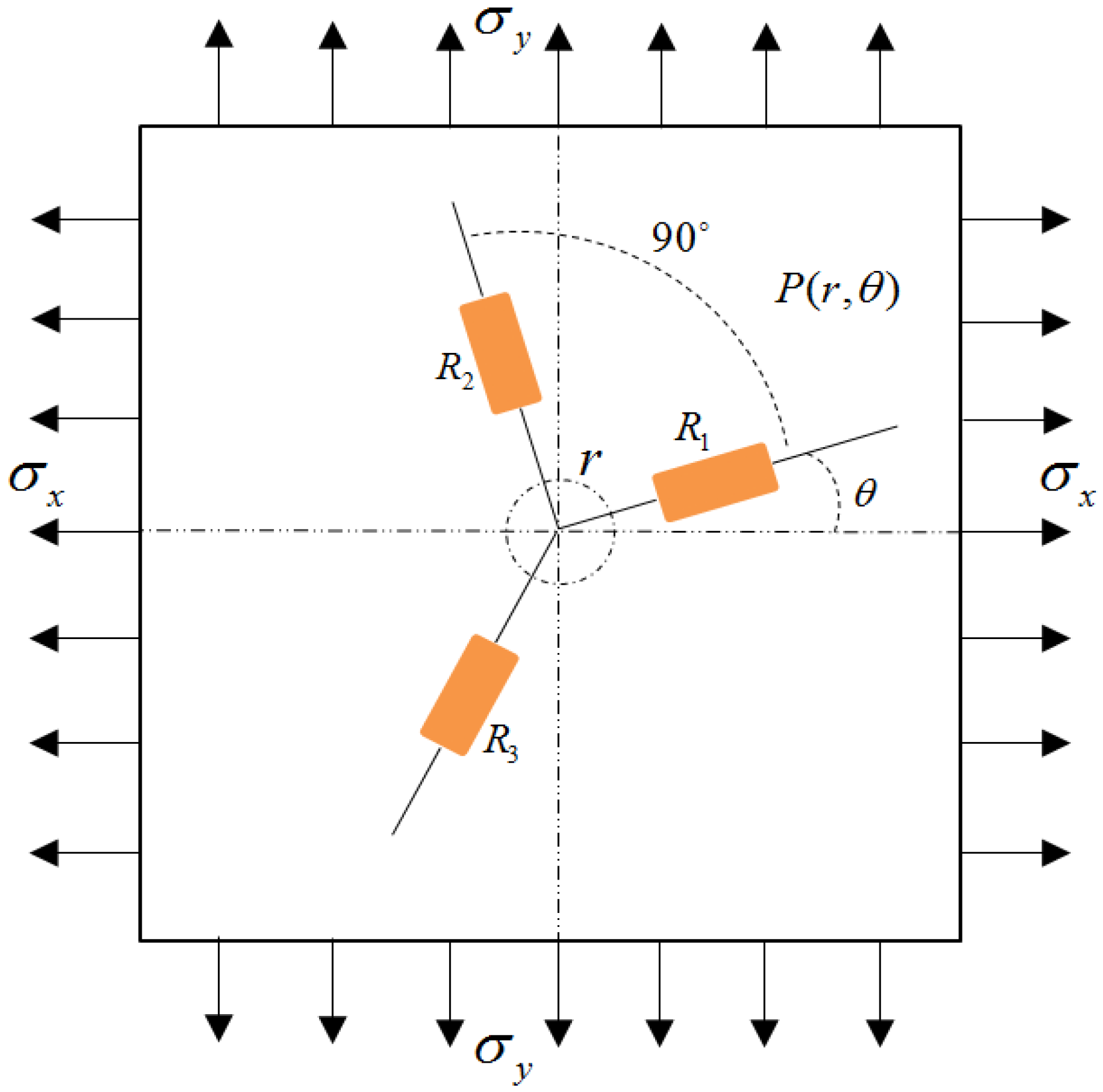
The evolution mechanism of welding residual stress and the factors affecting its formation are complicated. Theoretical analysis alone cannot solve the problem. Therefore, a destructive test using the hole-drilling method was applied to validate the correctness of the ultrasonic laser method. A ZDL-type drilling device and a TJ-120-1.5 type strain rosette were applied in the experiment. The local radial strain induced by boreholes was measured and the longitudinal and transverse stresses were calculated based on the following relationships:
where are the radial strains measured by the strain rosette. The strain rosette is composed of three different angle sensitive grids arranged in the radial direction. As shown in Figure 7, is the angle between the principal stress and the strain gauge . The release coefficients A and B can be obtained by the following formulas [36]:
where is the radius of the hole, is the distance between the center of the hole and the middle point of the sensitive grids, and are the elastic modulus and Poisson ratio, respectively. As shown in Figure 6, the longitudinal residual stresses measured with the hole-drilling method and the ultrasonic laser method were consistent. In the high stress region, the hole-drilling method produced a larger result than the ultrasonic laser due to the stress concentration caused by the hole.
4. Results and Discussion
When the welding component is in service, the superposition of the external load and internal residual stress leads to the redistribution of welding residual stress, which seriously affects the mechanical properties of the welded components, especially in terms of fatigue strength, brittle failure, and stress corrosion cracking. Therefore, it was necessary to study the effect of laser welding parameters on residual stress.
4.1. Effects of Heat Input on Residual Stress
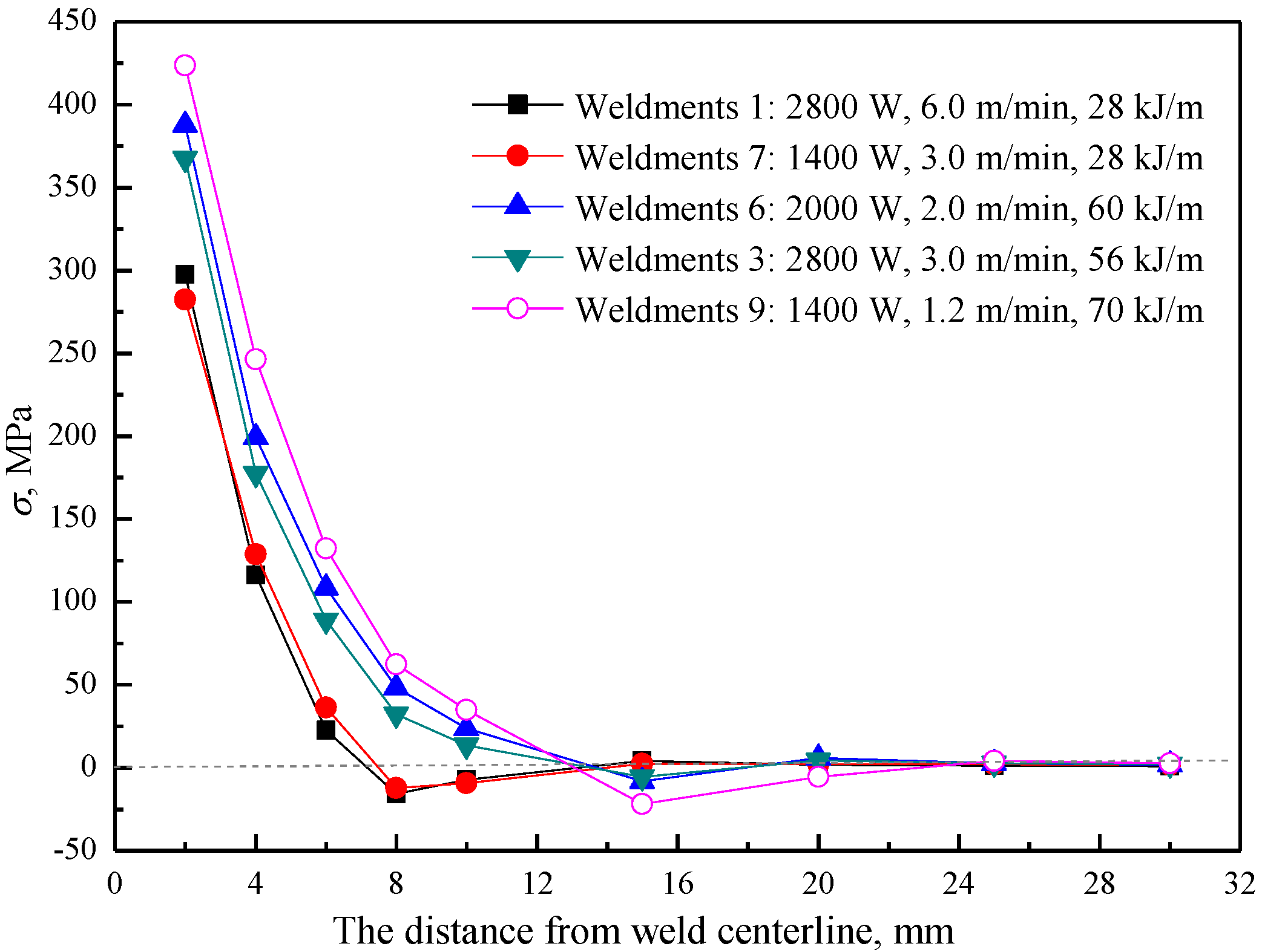
Figure 8 presents the longitudinal residual stress measurements for a series of laser welding, grouped by increasing heat input. Heat input considerably influenced residual stress. For welds 1 and 7 with the same heat input of 28 kJ/m, there was little change in the distribution and the maximum value of residual stress. The difference in the maximum tensile stress was less than 15 MPa. For the welds with different heat inputs, the maximum value of residual stress increased with increasing heat input. The width of the tensile longitudinal residual stress zone within the half plate was 7 mm with a heat input of 28 kJ/m, and 13 mm with a heat input of 60 kJ/m, which means that the stress gradient within the fusion zone of full laser penetration welding was steep. When the heat input increased, the energy absorbed by the unit length increased, which expanded the high temperature zone generation plastic deformation and the corresponding plastic deformation zone moved outside. Therefore, the tensile residual stress region increased.
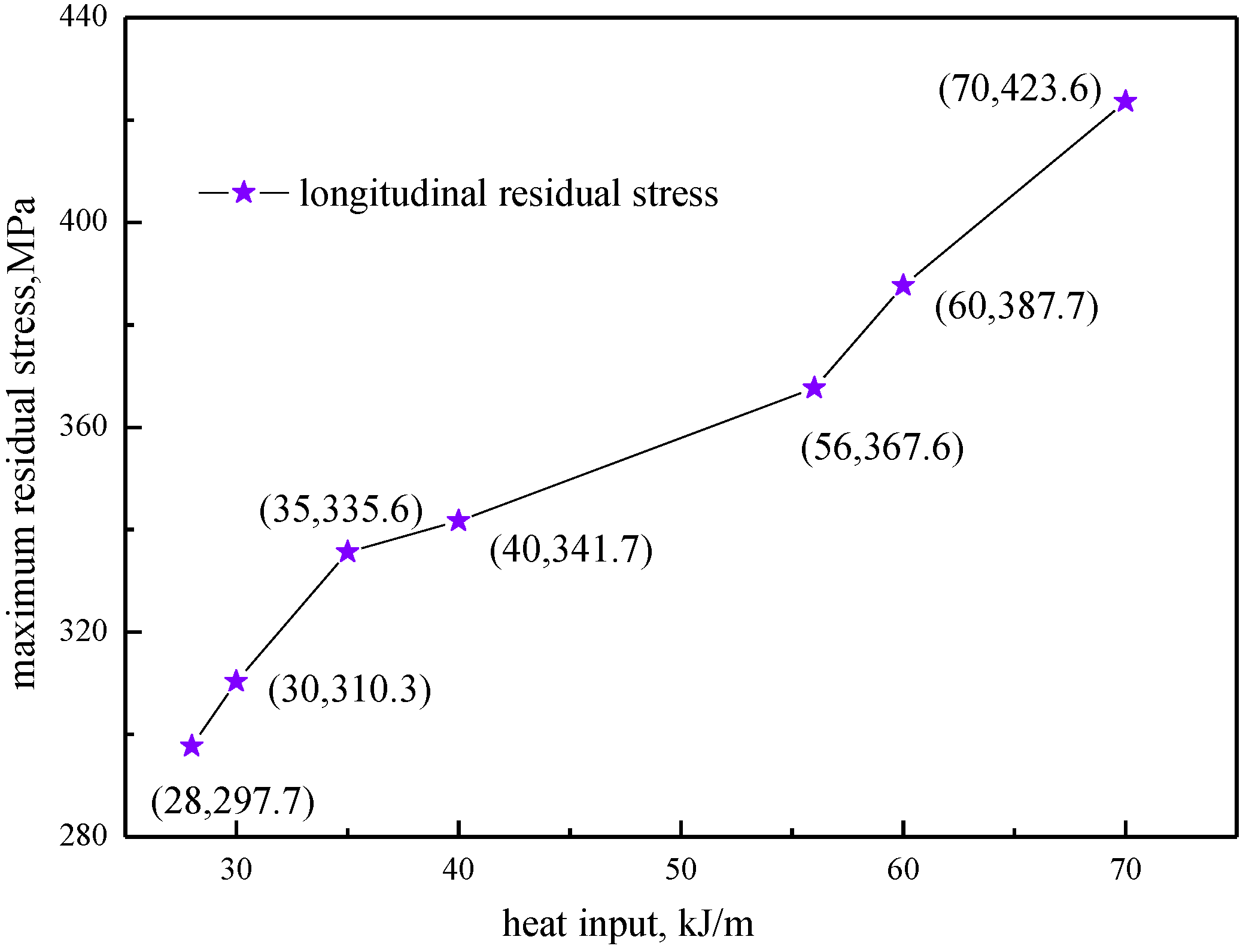
As shown in Figure 9, with increasing heat input, the maximum longitudinal residual stress gradually increased. The whole change process can be divided into three stages. During the first stage (heat input 28–35 kJ/m) and the third stage (heat input 56–70 kJ/m), the maximum residual stress changed markedly, which was mainly due to the large temperature gradient at high heat input and the small plastic deformation region at low heat input. When the heat input changed from 35 kJ/m to 56 kJ/m, the maximum longitudinal residual stress changed slowly. The deduction from these data is that the second stage may be the preferred heat input range for laser welding of 2-mm-thick titanium alloy plates when residual stress and other factors affecting welding quality are considered.
4.2. Effects of Welding Speed on Residual Stress
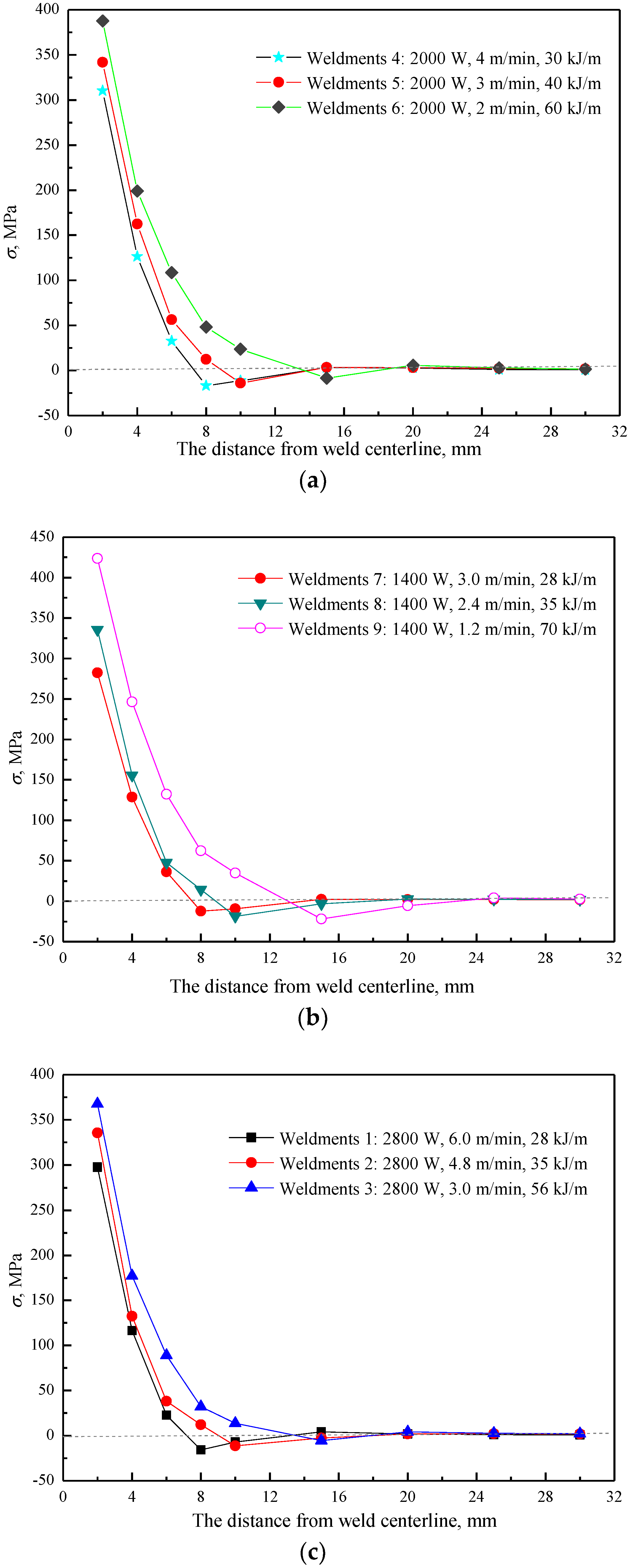
As an important process parameter of laser welding, welding speed directly determines the efficiency of welding. Figure 10 shows the effect of welding speed on residual stress distribution. It can be seen that with the increase in welding speed, the residual stress maximum decreases gradually due to the decrease in the energy absorbed by the weld per unit length caused by heat input changes. As the welding speed decreases, the tensile stress region increases due to the increase in the plastic deformation area caused by high heat input. Therefore, higher welding speeds should be chosen when the welding power is constant, to improve the welding efficiency and reduce the residual stress.
4.3. Effects of Heat Treatment on Residual Stress
The residual stress produced by laser welding of TC4 titanium alloy near the weld and fusion line was about 50% of the yield strength of the base material. Therefore, it was necessary to adopt laser welding and post-weld heat treatment to control the residual stress. In order to avoid oxidation and pollution of titanium alloy in air, a vacuum furnace with a precision of was used for heat treatment. The specimen was clamped with fastening bolts to eliminate its warp. In general, the heating temperature and the holding time determine the extent to which residual stresses are removed during heat treatment. In the experiment, the national standard GJB3763A was adopted, the heat treatment temperature was , and the holding time was 120 min. Then, the residual stress of the laser welding specimens after heat treatment was measured with an ultrasonic laser.
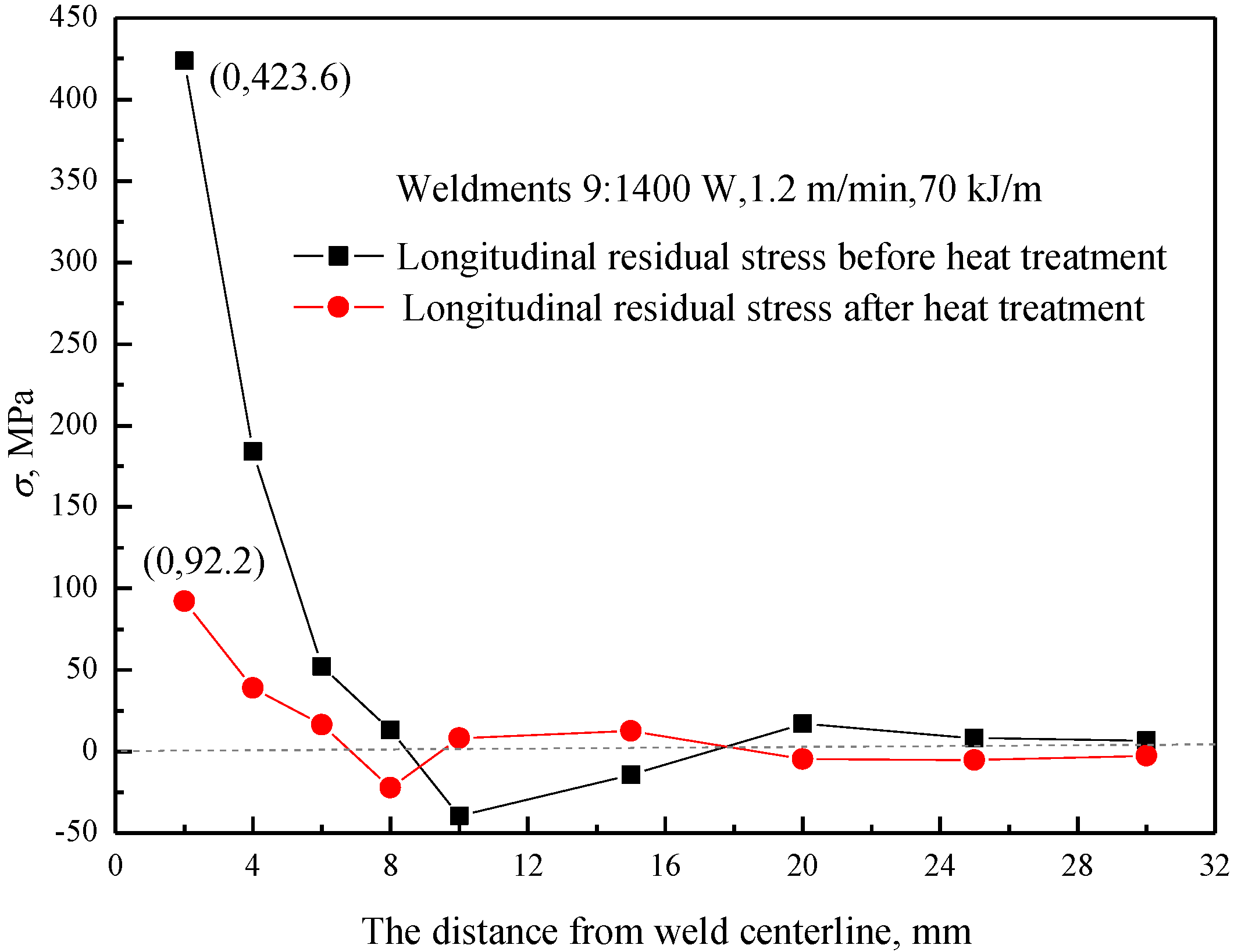
As shown in Figure 11, the longitudinal residual stress was greatly reduced. The decrease in the maximum of residual stress was particularly obvious. The maximum of the longitudinal residual stress was reduced from 423 to 92 MPa, a decrease of 78%, but the maximum residual stress after heat treatment was still larger. Due to the redistribution of the residual stress caused by heat treatment, partial tensile stress and compressive stress in the distant weld area were converted to each other. Although heat treatment can reduce residual stress to a certain extent, it was still necessary to control the residual stress by optimizing the welding process parameters.
5. Conclusions
An ultrasonic laser technique was used to measure the residual stress in laser welding of TC4 titanium alloy. A pre-stress loading method was proposed and the acoustoelastic coefficients of TC4 titanium alloys were first obtained. On the basis of known acoustoelastic coefficients, the longitudinal and transverse welding residual stresses were measured with an ultrasonic laser technique. The results showed that the longitudinal residual stress was obviously larger than the transverse stress. The longitudinal residual stress was high tensile stress near the welding seam, and the maximum value of longitudinal residual stress was about 420 MPa, which was half of the yield strength. Then, the effect of the process parameters on the features of the residual stress was discussed. The results showed that heat input is the dominant parameter determining laser welding residual stress. With increasing heat input, the welding zone widened and the peak value of the residual stress increased gradually. Higher welding speeds should be chosen as much as possible when the welding power is constant. Heat treatment can reduce the maximum of the longitudinal residual stress by about 80% and lead to the redistribution of stress.
Author Contributions
The work presented here was performed in collaboration among all authors. Y.Z. designed, analyzed, and wrote the paper. C.L. guided the full text. E.Z. and Y.G. provided and analyzed the experimental data. All authors contributed to and approved the manuscript.
Funding
The study is supported by the National Natural Science Foundation of China Project (Grant No. 51771051), Doctoral Research Foundation of Liaoning Province Project (Grant No. 20170520439) and the Fundamental Research Funds for the Central Universities (Grant No. N170504021).
Acknowledgment
Authors would like to acknowledge the help of senior engineer Lee of AVIC 601 Institute for providing the welding specimens and related process parameters. Furthermore, the authors would like to thank engineer Shan of Shenyang Aircraft Industrial Corporation for helping us to complete the post-weld heat treatment experiment.
Conflicts of Interest
The authors declare no conflict of interest.
References
- Ancona, A.; Sibillano, T.; Lugara, P.M.; Gonnella, G.; Pascazio, G. An analysis of the shielding gas flow from a coaxial conical nozzle during high power CO2 laser welding. J. Phys. D Appl. Phys. 2006, 39, 563–574. [Google Scholar] [CrossRef]
- Akman, E.; Demir, A.; Canel, T.; Sınmazc, T. Laser welding of Ti6Al4V titanium alloys. J. Mater. Process. Technol. 2009, 209, 3705–3713. [Google Scholar] [CrossRef]
- Gao, X.L.; Zhang, L.J.; Liu, J.; Zhang, J.X. A comparative study of pulsed Nd:YAG laser welding and TIG welding of thin Ti6Al4V titanium alloy plate. Mater. Sci. Eng. A 2013, 559, 14–21. [Google Scholar] [CrossRef]
- Kashaev, N.; Ventzke, V.; Fomichev, V.; Fomin, F.; Riekehr, S. Effect of Nd:YAG laser beam welding on weld morphology and mechanical properties of Ti–6Al–4V butt joints and T-joints. Opt. Lasers Eng. 2016, 86, 172–180. [Google Scholar] [CrossRef]
- Lim, C.; Nin, J.; Guilemany, J.M. Evaluation of residual stresses of thermal barrier coatings with HVOF thermally sprayed bond coats using the modified layer removal method. Surf. Coat. Technol. 2006, 200, 5963–5972. [Google Scholar] [CrossRef]
- Baldi, A. Residual stress measurement using hole drilling and integrated digital image correlation techniques. Exp. Mech. 2014, 54, 379–391. [Google Scholar] [CrossRef]
- Koester, L.W.; Taheri, H.; Bigelow, T.A.; Collins, P.C.; Bond, L.J. Nondestructive testing for metal parts fabricated using powder-based additive manufacturing. Mater. Eval. 2018, 76, 514–524. [Google Scholar]
- Dixon, S.; Burrows, S.E.; Dutton, B.; Fan, Y. Detection of cracks in metal sheets using pulsed laser generated ultrasound and EMAT detection. Ultrasonics 2011, 51, 7–16. [Google Scholar] [CrossRef] [PubMed] [Green Version]
- Lowe, M.J.S.; Alleyne, D.N.; Cawley, P. Defect detection in pipes using guided waves. Ultrasonics 1998, 36, 147–154. [Google Scholar] [CrossRef]
- Duquennoy, M.; Ouaflouh, M.; Qian, M.L.; Jenot, F.; Ourak, M. Ultrasonic characterization of residual stresses in steel rods using a laser line source and piezoelectric transducers. NDT&E Int. 2001, 34, 355–362. [Google Scholar]
- Ruiz, A.M.; Nagy, P.B. Diffraction correction for precision surface acoustic wave velocity measurements. J. Acoust. Soc. Am. 2002, 112, 835–842. [Google Scholar] [CrossRef] [PubMed]
- Bescond, C.; Monchalin, J.P.; Gilbert, A.; Talbot, R.; Ochiai, M. Determination of residual stresses using laser-generated surface skimming longitudinal waves. Proc. SPIE 2005, 5767, 175–186. [Google Scholar]
- Doxbeck, M.; Hussain, M.A.; Frankel, J. Use of laser generated creeping longitudinal waves to determine residual stresses. IEEE Ultrason. Symp. 2000, 73, 725–728. [Google Scholar]
- Moreau, A.; Man, C.S. Laser-ultrasonic measurements of residual stresses in a 7075-T651 aluminum sample surface-treated with low plasticity burnishing. Proc. SPIE 2006, 820, 1434. [Google Scholar]
- Dong, L.M.; Li, J.; Ni, C.Y.; Shen, Z.H.; Ni, X.W. Evaluation of residual stresses using laser-generated SAWs on surface of laser-welding plates. Int. J. Thermophys. 2013, 34, 1066–1079. [Google Scholar] [CrossRef]
- Karabutov, A.; Devichensky, A.; Ivochkin, A. Laser ultrasonic diagnostics of residual stress. Ultrasonics 2008, 48, 631–635. [Google Scholar] [CrossRef] [PubMed]
- Sanderson, R.M.; Shen, Y.C. Measurement of residual stress using laser-generated ultrasound. Int. J. Press. Vessel. Pip. 2010, 87, 762–765. [Google Scholar] [CrossRef]
- Fernandes, F.A.O.; Oliveira, D.F.; Pereira, A.B. Optimal parameters for laser welding of advanced high-strength steels used in the automotive industry. Procedia Manuf. 2017, 13, 219–226. [Google Scholar] [CrossRef]
- Xue, X.; Pereira, A.B.; Amorim, J.; Liao, J. Effects of pulsed Nd:YAG laser welding parameters on penetration and microstructure characterization of a DP1000 steel butt joint. Metals 2017, 7, 292. [Google Scholar] [CrossRef]
- Li, S.; Xu, W.; Su, F.; Deng, H.; Deng, Z. Influence of CO2 shielding gas on high power fiber laser welding performance. Metals 2018, 8, 449. [Google Scholar] [CrossRef]
- Popescu, A.C.; Delval, C.; Leparoux, M. Control of porosity and spatter in laser welding of thick AlMg5 parts using high-speed imaging and optical microscopy. Metals 2017, 11, 452. [Google Scholar] [CrossRef]
- Lee, H.K.; Han, H.S.; Son, K.J.; Hong, S.B. Optimization of Nd:YAG laser welding parameters for sealing small titanium tube ends. Mater. Sci. Eng. A 2006, 415, 149–155. [Google Scholar] [CrossRef]
- Crecraft, D.L. The measurement of applied and residual stress in metals using ultrasonic waves. J. Sound Vib. 1967, 5, 173–192. [Google Scholar] [CrossRef]
- Truell, R.; Chick, B.; Elbaum, C. Ultrasonic Methods in Solid State Physics; Academic Press: New York, NY, USA, 1969. [Google Scholar]
- Egle, D.M.; Bray, D.E. Measurement of acoustoelastic and third-order elastic constant for rail steel. J. Acoust. Soc. Am. 1979, 37, 41–55. [Google Scholar]
- Jassby, K.M.; Aharoni, A.; Cohen, N. Determining surface residual stress in isotropic solids by combined ultrasonic velocity measurements. Ultrasonics 1985, 23, 79–85. [Google Scholar]
- Duqennoy, M.; Ouaftouh, M.; Ourak, M. Determination of stresses in aluminum alloy using optical detection of Rayleigh waves. Ultrasonics 1999, 37, 365–372. [Google Scholar] [CrossRef]
- Hirao, M.; Fukuoka, H.; Hori, K. Acoustoelastic effect of Rayleigh surface wave in isotropic material. J. Appl. Mech. 1981, 48, 119–124. [Google Scholar] [CrossRef]
- Hayes, M.; Rivlin, R.S. Surface waves in deformed elastic materials. Arch. Ration. Mech. Anal. 1961, 8, 359–380. [Google Scholar] [CrossRef]
- Pao, Y.H.; Sachse, W.; Fukuoka, H. Acoustoelasticity and Ultrasonic Measurememt of Residual Stress, in Physical Acoustics: Principles and Methods; Academic Press: New York, NY, USA, 1984; pp. 61–143. [Google Scholar]
- Husson, D. A perturbation theory for the acoustoelastic effect of surface waves. J. Appl. Phys. 1985, 57, 1562–1568. [Google Scholar] [CrossRef]
- Dunstan, D.J.; Bosher, S.H.B.; Downes, J.R. Effective thermodynamic elastic constants under finite deformation. Appl. Phys. Lett. 2002, 80, 2672. [Google Scholar] [CrossRef]
- Zhan, Y.; Liu, C.S.; Zhang, F.P.; Qiu, Z.G. Experimental study and finite element analysis based on equivalent load method for laser ultrasonic measurement of elastic constants. Ultrasonics 2016, 69, 243–247. [Google Scholar] [CrossRef] [PubMed]
- Auld, B.A. Acoustic Fields and Waves in Solids; Wiley Interscience: New York, NY, USA, 1973; Volume 1. [Google Scholar]
- Ya, M.; Marquette, P.; Belahcene, F.; Lu, J. Residual stresses in laser welded aluminium plate by use of ultrasonic and optical methods. Mater. Sci. Eng. A 2004, 382, 257–264. [Google Scholar] [CrossRef]
- Dai, F.L.; Shen, G.L.; Xie, H.M. Experimental Mechanics; Tsinghua University Press: Beijing, China, 2010. [Google Scholar]
Figure 1.
Experimental system: (a) ultrasonic laser and (b) pre-stress loading apparatus.

Figure 2.
Travel time of surface waves in the base material without stress. The change in distance is , Channel 1 is the vibration signal, Channel 2 is the time reference signal, a and b are the cursors for reading travel time.
Figure 2.
Travel time of surface waves in the base material without stress. The change in distance is , Channel 1 is the vibration signal, Channel 2 is the time reference signal, a and b are the cursors for reading travel time.

Figure 3.
Linear fitting curve of the experimental results, the slope represents the velocity of surface wave propagation in the TC4 base material.
Figure 3.
Linear fitting curve of the experimental results, the slope represents the velocity of surface wave propagation in the TC4 base material.

Figure 4.
The relationship between velocity ratio and tensile stress. The slopes of the linear fitting curve correspond to the acoustoelastic coefficients.
Figure 4.
The relationship between velocity ratio and tensile stress. The slopes of the linear fitting curve correspond to the acoustoelastic coefficients.

Figure 5.
(a) Experimental specimen and (b) layout of measuring line when measuring the velocity , where is a measurement point; is the measuring line; , , and are the auxiliary lines; and and are the positions of the laser beam.
Figure 5.
(a) Experimental specimen and (b) layout of measuring line when measuring the velocity , where is a measurement point; is the measuring line; , , and are the auxiliary lines; and and are the positions of the laser beam.

Figure 6.
The residual stress distribution in TC4 laser welding at a welding power of 2800 W, welding speed of 6.0 m/min, and heat input of 28 kJ/m. The longitudinal residual stresses measured by the hole-drilling method and ultrasonic laser method were consistent.
Figure 6.
The residual stress distribution in TC4 laser welding at a welding power of 2800 W, welding speed of 6.0 m/min, and heat input of 28 kJ/m. The longitudinal residual stresses measured by the hole-drilling method and ultrasonic laser method were consistent.

Figure 7.
Diagram of sensitive grid arrangement is the angle between the principal stress and the strain gauge , and the angle between the strain gauge and is .
Figure 7.
Diagram of sensitive grid arrangement is the angle between the principal stress and the strain gauge , and the angle between the strain gauge and is .

Figure 8.
Longitudinal residual stress distribution with different heat inputs.

Figure 9.
The relationship between maximum longitudinal residual stress and heat input. Three approximate linear stages are presented and the maximum residual stress changes slowly in the second stage.
Figure 9.
The relationship between maximum longitudinal residual stress and heat input. Three approximate linear stages are presented and the maximum residual stress changes slowly in the second stage.

Figure 10.
The longitudinal residual stress distribution with the same welding power: (a) 2000 W, (b) 1400 W, and (c) 2800 W.
Figure 10.
The longitudinal residual stress distribution with the same welding power: (a) 2000 W, (b) 1400 W, and (c) 2800 W.

Figure 11.
Comparison of the longitudinal residual stress before and after heat treatment. The maximum of longitudinal residual stress was reduced from 423 MPa to 92 MPa, a decrease of 78%.
Figure 11.
Comparison of the longitudinal residual stress before and after heat treatment. The maximum of longitudinal residual stress was reduced from 423 MPa to 92 MPa, a decrease of 78%.


Table 1.
The composition of TC4.
| Material | Al | V | Fe | Si | C | O | N | H | Ti |
|---|---|---|---|---|---|---|---|---|---|
| TC4 | 5.5–6.8 | 3.5–4.5 | 0.3 | 0.15 | 0.1 | 0.2 | 0.05 | 0.015 | Balance |
Table 2.
Laser welding process parameters.
| Weld No. | Welding Power (W) | Welding Speed | Heat Input |
|---|---|---|---|
| 1 | 2800 | 6.0 | 28 |
| 2 | 2800 | 4.8 | 35 |
| 3 | 2800 | 3.0 | 56 |
| 4 | 2000 | 4.0 | 30 |
| 5 | 2000 | 3.0 | 40 |
| 6 | 2000 | 2.0 | 60 |
| 7 | 1400 | 3.0 | 28 |
| 8 | 1400 | 2.4 | 35 |
| 9 | 1400 | 1.2 | 70 |
© 2018 by the authors. Licensee MDPI, Basel, Switzerland. This article is an open access article distributed under the terms and conditions of the Creative Commons Attribution (CC BY) license (http://creativecommons.org/licenses/by/4.0/).
Share and Cite
MDPI and ACS Style
Zhan, Y.; Zhang, E.; Ge, Y.; Liu, C. Residual Stress in Laser Welding of TC4 Titanium Alloy Based on Ultrasonic laser Technology. Appl. Sci. 2018, 8, 1997. https://0-doi-org.brum.beds.ac.uk/10.3390/app8101997
AMA Style
Zhan Y, Zhang E, Ge Y, Liu C. Residual Stress in Laser Welding of TC4 Titanium Alloy Based on Ultrasonic laser Technology. Applied Sciences. 2018; 8(10):1997. https://0-doi-org.brum.beds.ac.uk/10.3390/app8101997
Chicago/Turabian StyleZhan, Yu, Enda Zhang, Yiming Ge, and Changsheng Liu. 2018. "Residual Stress in Laser Welding of TC4 Titanium Alloy Based on Ultrasonic laser Technology" Applied Sciences 8, no. 10: 1997. https://0-doi-org.brum.beds.ac.uk/10.3390/app8101997
Note that from the first issue of 2016, this journal uses article numbers instead of page numbers. See further details here.