Agustín de Betancourt’s Double-Acting Steam Engine: Analysis through Computer-Aided Engineering


1
Department of Engineering Graphics, Design and Projects, University of Jaén, 23071 Jaén, Spain
2
‘Engineering Graphics and Industrial Archaeology’ Research Group, University of Jaén, 23071 Jaén, Spain
*
Author to whom correspondence should be addressed.
Appl. Sci. 2018, 8(11), 2309; https://0-doi-org.brum.beds.ac.uk/10.3390/app8112309
Submission received: 2 October 2018
/
Revised: 16 November 2018
/
Accepted: 16 November 2018
/
Published: 20 November 2018
(This article belongs to the Special Issue Applied Sciences to the Study of Technical Historical Heritage and/or Industrial Heritage)
Abstract
:This article analyses the double-acting steam engine designed by Agustín de Betancourt in 1789 and based on the steam engine of James Watt. Its novelty and scientific interest lies in the fact that from the point of view of industrial archaeology and the study of technical historical heritage there is no worldwide study on this invention, which marked a historic milestone in the design of the steam engines of the Industrial Revolution (1760–1840). This underscores the utility and originality of this research. To this end, a study of computer-aided engineering (CAE) was carried out using the parametric software Autodesk Inventor Professional, consisting of a static analysis using the finite-element method of the 3D CAD model of the invention under real operating conditions. The results have shown that the double-acting steam engine was correctly designed considering that the values of the maximum von Mises stress (188.4 MPa) obtained were taken away from the elastic limit of the material it was made of (cast iron), as well as to the maximum deformations (0.14% with respect to its length) obtained in the same element that presents the maximum stress (opening axle of the high pressure steam valve). Similarly, the maximum displacements (18.74 mm) are located in the mobile counterweights that transmit certain inertia to facilitate the opening and closing of the valves. Finally, if we look at the results of the safety coefficient, whose lowest value was 4.02, we could say that the invention was oversized, following constructive criteria of the time, as there were no resistance tests on materials that would help in the optimization of the design of the invention.
1. Introduction
Agustín de Betancourt y Molina was one of the fathers of engineering in the period of the Spanish Enlightenment [1]. This article aims to analyse from the point of view of engineering one of the most controversial inventions of his career, the double-acting steam engine, the first steam engine of its kind to reach the European continent. This invention has already been the object of a detailed study from the graphic engineering point of view, which has allowed us to obtain a reliable 3D CAD model [2] from which the present investigation has been carried out and which led to the discovery of the concept of energy symmetry with which Betancourt designed this invention. Its novelty and scientific interest lies in the fact that from the point of view of industrial archaeology and the study of technical historical heritage there is no worldwide study on this invention, which marked a historic milestone in the design of the steam engines of the Industrial Revolution (1760–1840). This underscores the utility and originality of this research.
Until the end of the eighteenth century, the steam engine known in Europe was that of the English inventor Thomas Newcomen, a simple steam engine that worked thanks to pressure differences in the two chambers of a cylinder. This invention worked from the cooling of the water vapor inside the cylinder, which produced a vacuum. The upper face of the piston, open to the atmosphere, pushed it downward causing it to return to its initial lower position. This movement of the piston operated a rocker arm that impelled other rotating elements through a connecting rod-crank mechanism [3]. Subsequently, James Watt (mechanical engineer and Scottish inventor) worked from 1765 on the Newcomen steam engine, introducing a new element (the condenser) that would triple the performance compared to its predecessor. This simple element allowed advantage to be taken not only of the vacuum produced by the water vapor when condensing but also its expansion, decreasing in this way the amount of water vapor necessary to produce the movement of the piston. He also introduced other elements to increase performance such as the planetary gear system that facilitated the movement of the inertia flywheel, among others.
In 1782 the patent of James Watt reached perfection, when the Scottish engineer adapted the superior part of the cylinder so that the admission of the steam could be realized as much below as above the piston allowing the push of the steam on both its faces.
He also improved the rocker arm designed by Thomas Newcomen. Initially, this rocker arm was attached to the cylinder by means of a chain and therefore only transmitted the movement when the piston moved in the downward direction in the cylinder [3]. However, the double-acting steam engine was attached to the rocker arm by means of a lever that connected the piston shaft to the end of the rocker arm. By means of this connection, the upward stroke of the piston was also exploited but it presented the difficulty of adapting a certain movement of oscillation in the axle of the piston since, while the rocker arm described a circular movement, the axle of the piston moved vertically. Despite the joints (Watt’s extended mechanism consisting of an articulated parallelogram) designed to eliminate this movement and ensure an effective rectilinear guidance of the piston, the engine in use presented a significant maladjustment [3].
In September 1785, Betancourt began his second stay in Paris, where he returned with a double commission: to supervise the group of Spanish pensioners and to obtain plans and documents for the Royal Cabinet of Machines of Buen Retiro. During those years, he travelled through different factories and French ports taking notes and making known in Spain a large number of ideas and new techniques with which to stimulate the country’s industrial progress. It is during this period that he became aware of the existence of James Watt’s steam engine and the enormous progress it represented compared to that of Newcomen [4].
The Spanish engineer, interested in the news about the steam engine, obtained an interview in November 1788 with its inventors James Watt and Matthew Boulton, to be told about their patent. They showed him their factories of buttons and plated silver but none of their steam engines. Even so, he managed to visit the Albion Mills which were being built near the Blackfriars bridge. This installation consisted of three steam engines, one of which was completed [5].
So on December 16, 1789, he presented to the Academy of Sciences of Paris a double-acting steam engine based on the one designed by Watt but improved where it included the theoretical study of the extended mechanism of Watt, as well as solving for the first time in the history of the mechanisms a problem of synthesis of generation of trajectories with three points of precision [6].
As a result of his studies on the steam engine he wrote a memoir on the expansive force of water vapor, which obtained the approval of the Paris Academy of Sciences in September of that same year [7].
2. Materials and Methods
The starting material was only the information available on the website of the Betancourt Project of the Canary Orotava Foundation for the History of Science [12]. Here the information related to the invention is shown, as well as the letter written to his brother José on March 6, 1789 in which he gives news of his steam engine and the report of the Academy of Sciences of Paris on the examination of the invention, signed by Jean-Charles Borda, Mathurin-Jacques Brisson and Gaspard Monge [5].
On the other hand, there are two Betancourt works directly related to this invention. On the one hand in 1790 Betancourt wrote his ‘Mémoire sur la force expansive de la vapeur de l’eau’ [7], which was one of the first treatises on applied thermodynamics in which the results of the experiments carried out with the double-acting steam machine were shown; and on the other hand, the ‘Explication d’une machine destinée à curer les ports de mer’ (1808) [13], in which he proposes the design of a mechanical dredger installed on a ship and whose mechanism is propelled by its double- acting steam engine. In this second case, both in the drawings and in the memoir, Betancourt explains the mechanism of the double-acting steam engine, although in less detail.
To obtain the 3D CAD model of the steam engine [2], both the six sheets and the 34-page memory were used, explaining the invention and its operation, which appear in the original Betancourt file [5].
Once the 3D CAD model was obtained the methodology followed for the static analysis object of the present investigation was the same as that used in the study of other Betancourt inventions [14,15,16,17], giving it a substantial degree of credibility.
2.1. Operation of the Double-Acting Steam Engine
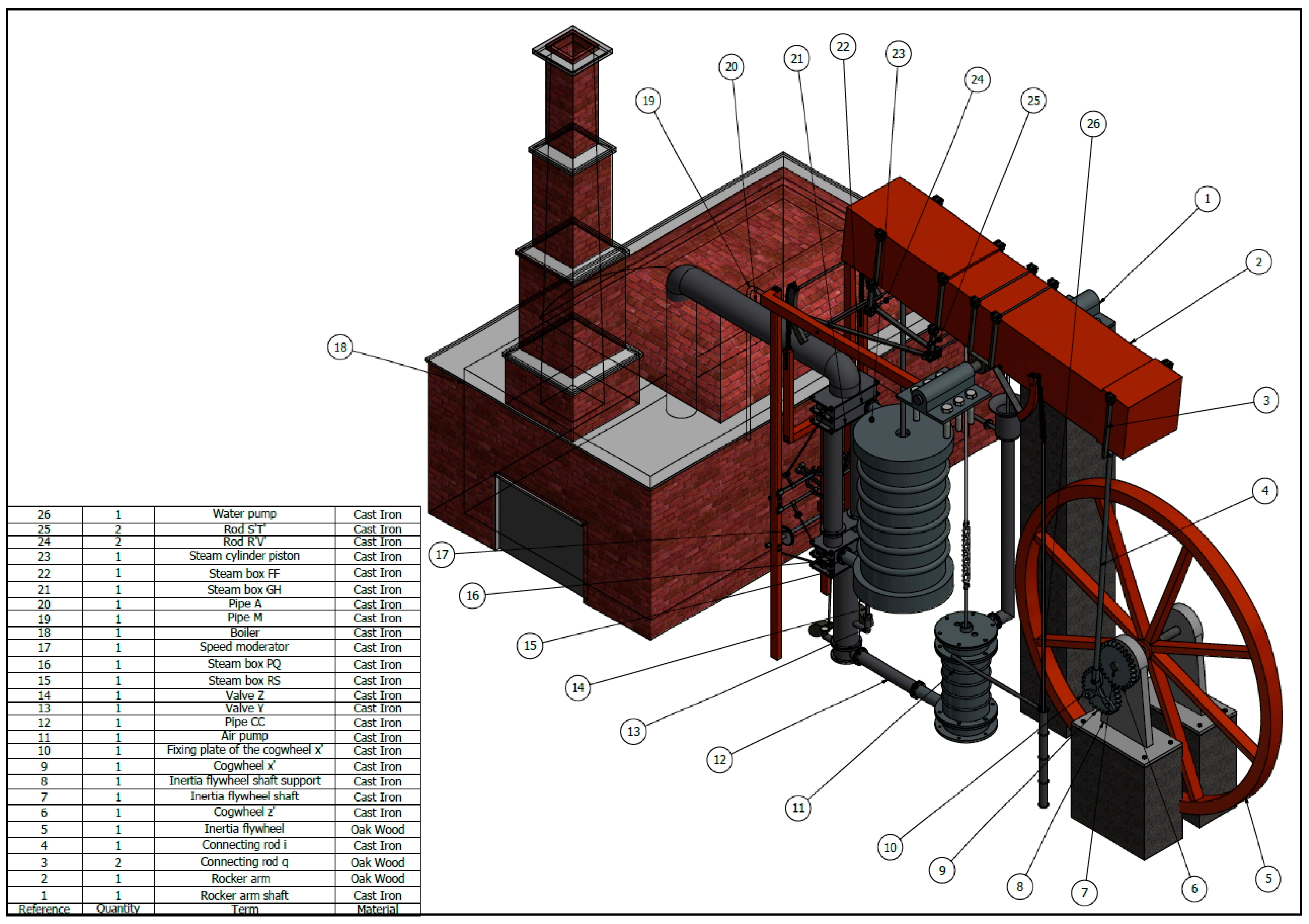
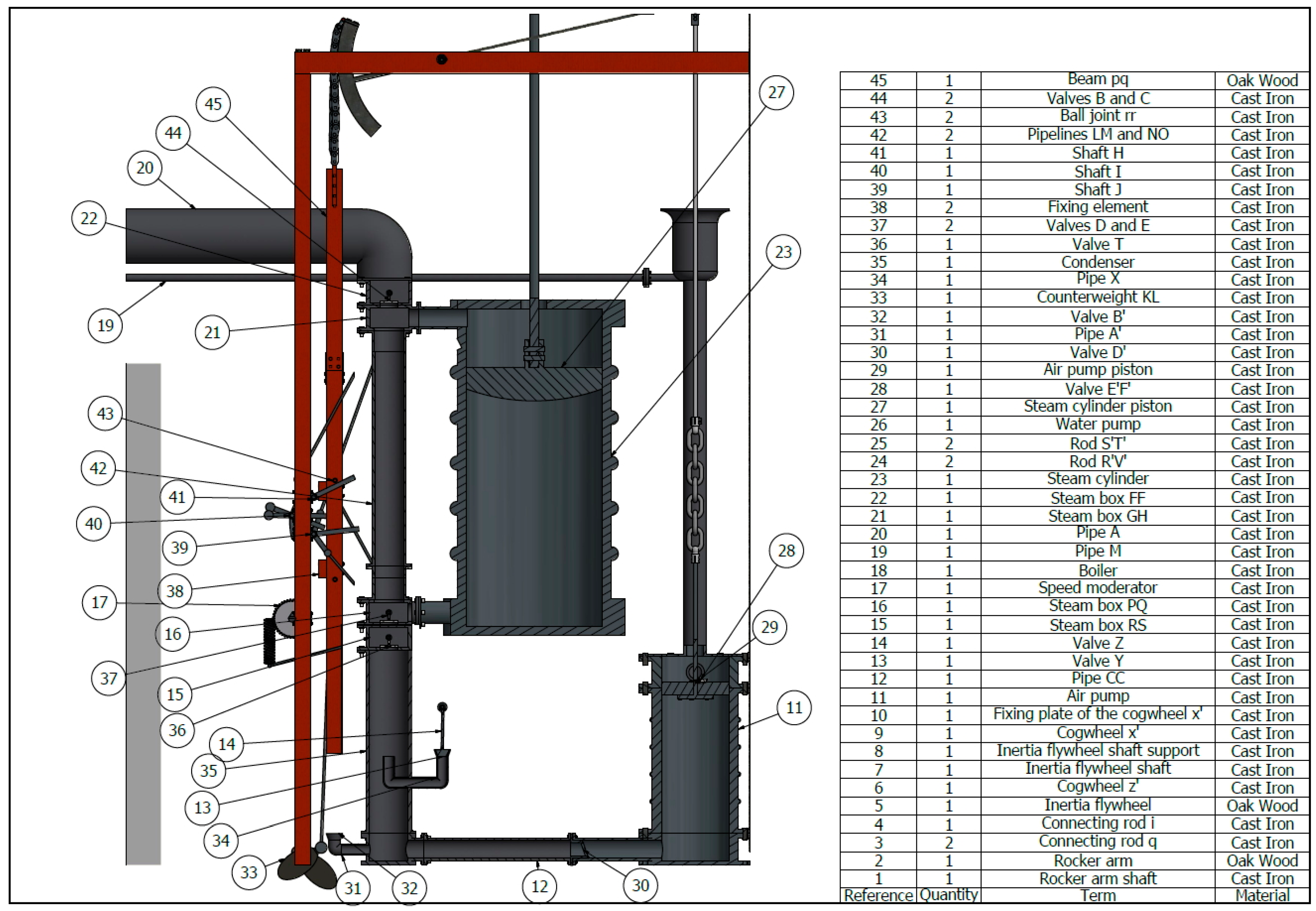
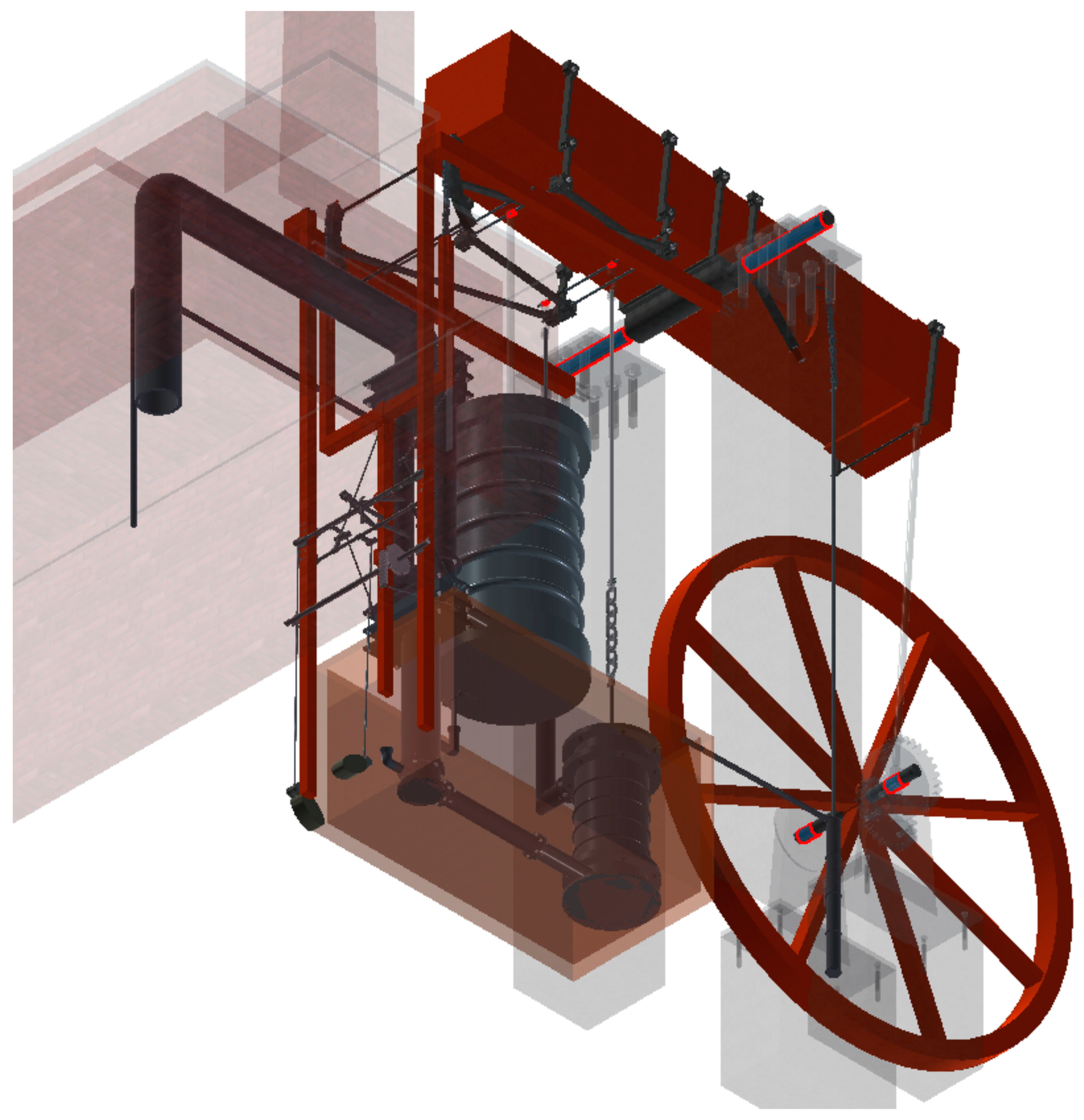
Although the 3D CAD model of the double-acting steam engine and its operation are perfectly described in the previously referenced publication [2], it has been considered convenient to briefly summarize it in order to facilitate the reader’s understanding, due to the high number of components and the complexity of the invention. This explanation is based on two plans along with an indication of the elements that compose the invention (Figure 1 and Figure 2).
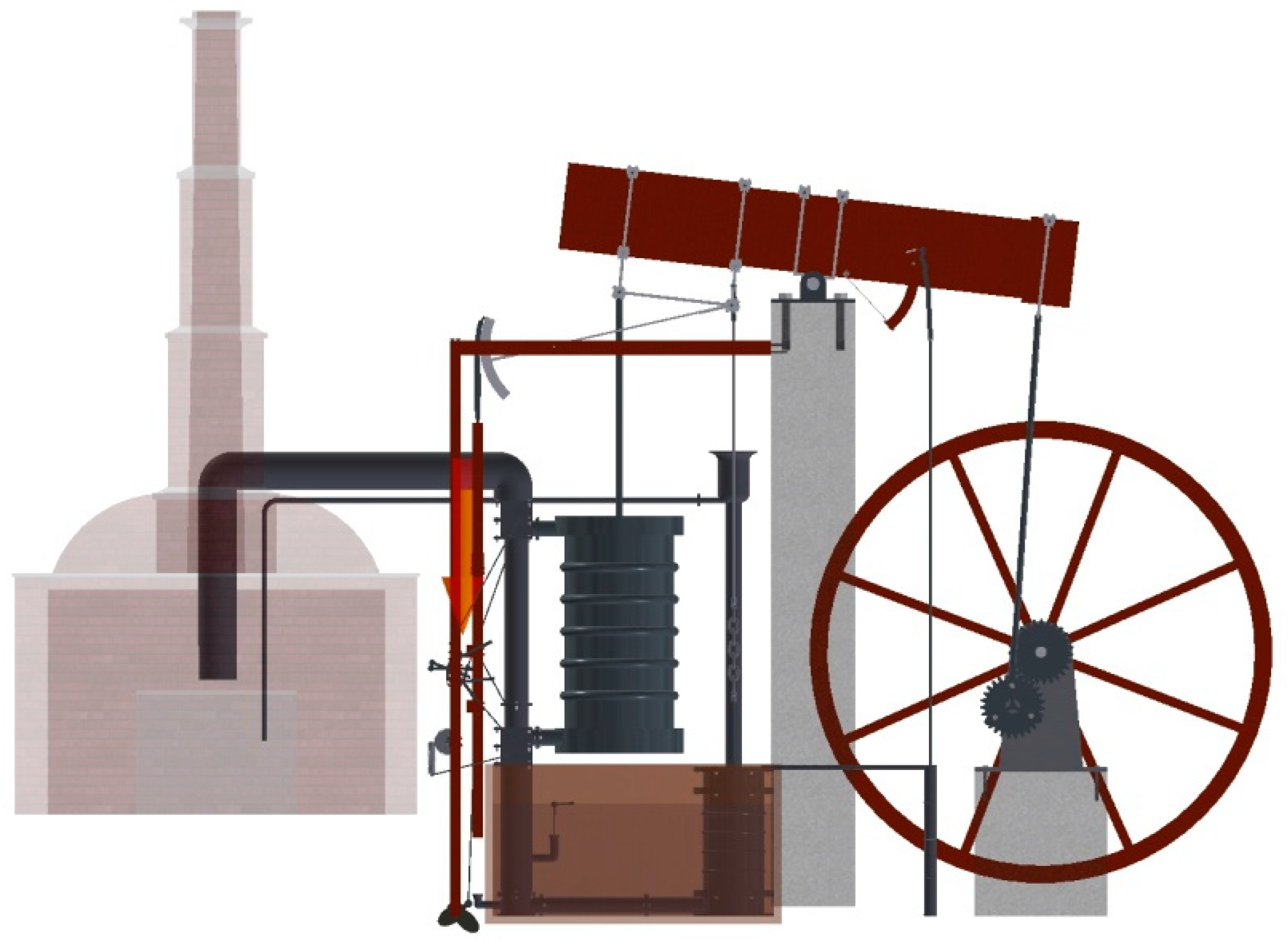
Figure 1 represents an isometric view of the set where it can be seen first, a brick building that houses the boiler (18) of the steam engine. This building is not large and fits the models of coal boilers of the time. Secondly, there is a large rocker arm whose balancing axis is supported by two square section columns (the previous one omitted to better see the rest of the elements). Finally, to the left and right of these columns there are two well differentiated parts: on the right, a handle-crank mechanism that moves an inertia flywheel (5) of large dimensions and on the left, the hydro-pneumatic circuit composed of a series of components that regulate its movement.
Through the metal doors of the brick building there is access to a room where the water located in a large boiler over a concave space is heated. In this space coal is burned, causing a thermal plume in the lower zone of the boiler so that the water in the boiler reaches a temperature of 100 °C, transforming it into steam and it leaves the boiler building through an upper pipe A (20).
The steam at high temperature reaches a steam box FF (22) that functions as a double-pass valve, that is, one position allows entry to the upper area of the steam cylinder (23) and the other position directs the steam to the lower steam box PQ (16). Thus, the valve system makes it possible to direct the water vapor to the upper or lower face of the piston (27). Valves B and C (44) are correlated to valves D and E (37), so that when the right valve of the upper steam box is open the left valve is closed and in those of the lower steam box the opposite occurs, the right valve closes and the left valve opens.
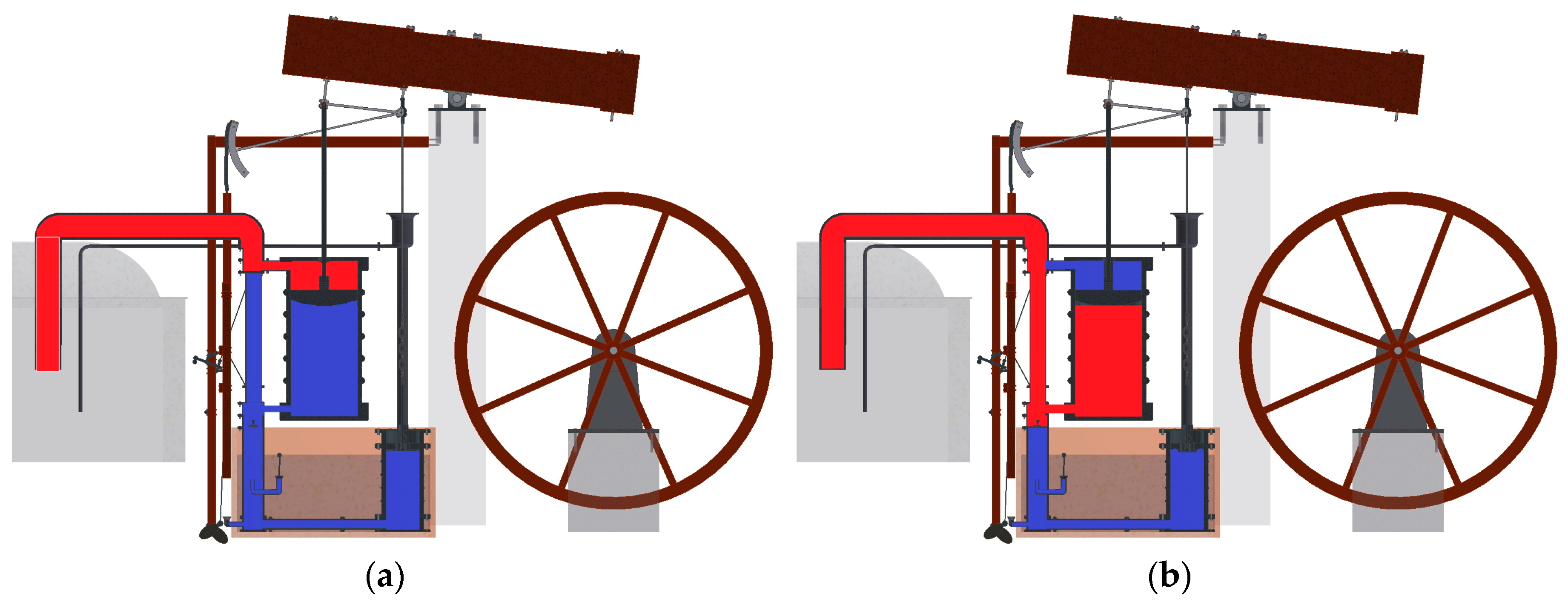
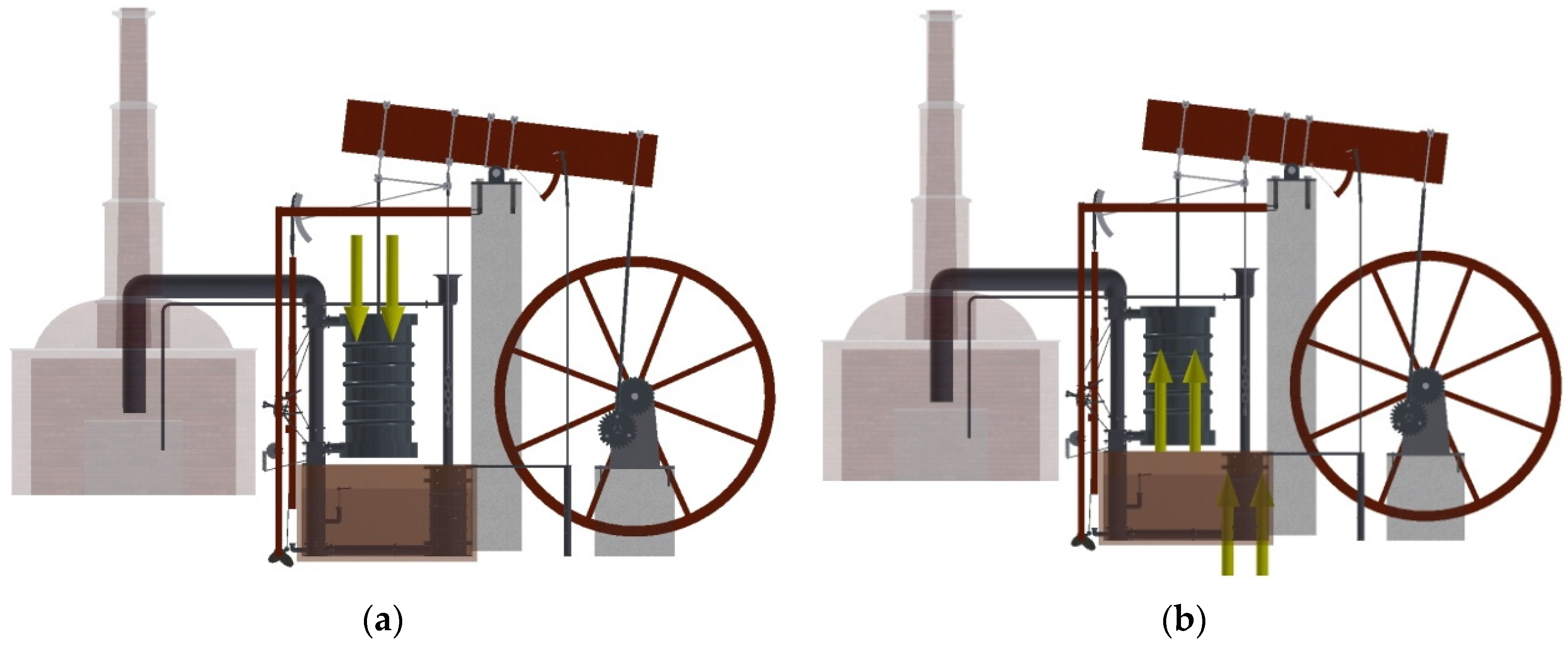
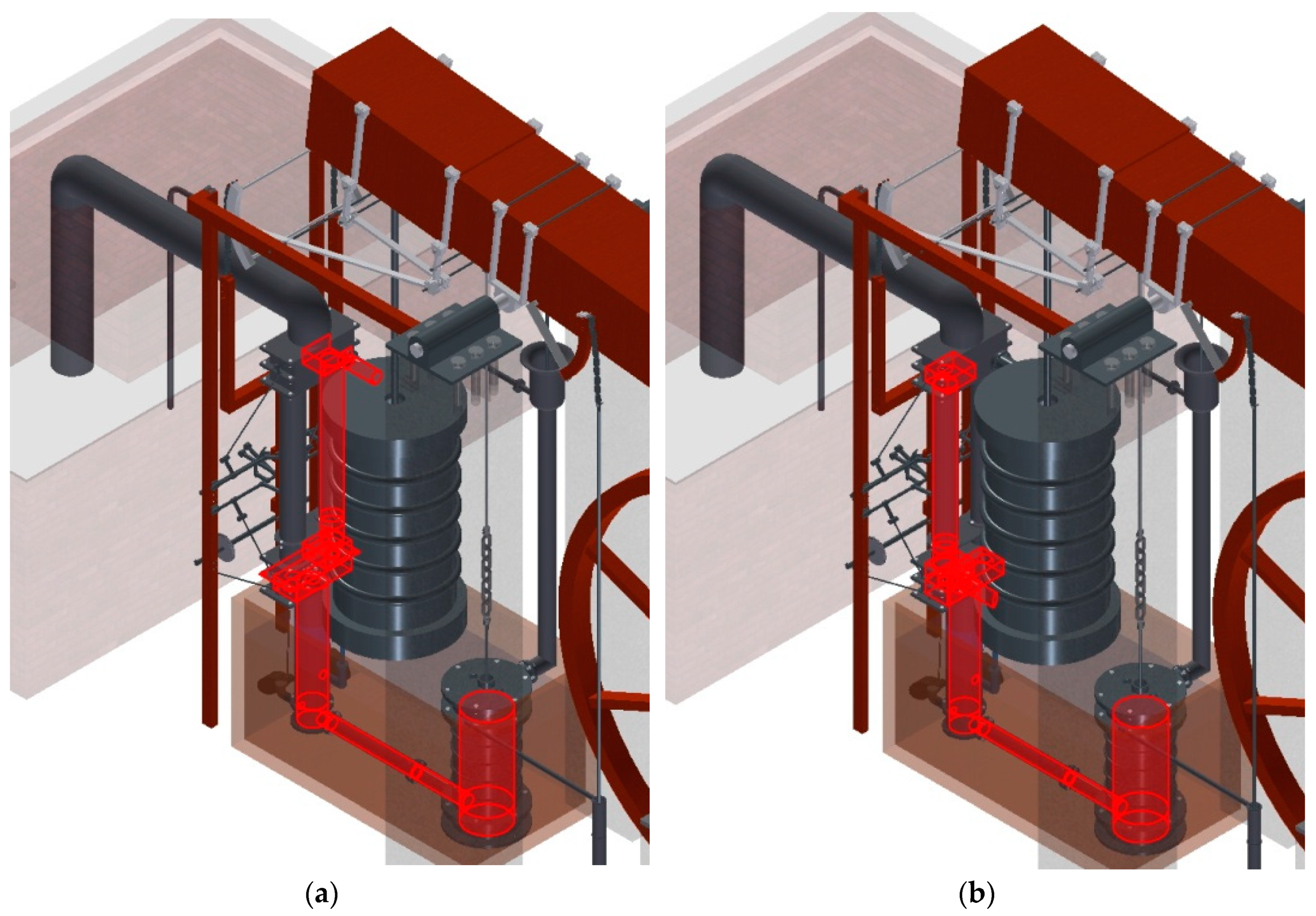
Figure 3 shows the path of the water vapor in the pipes depending on the action of the valves. Figure 3a shows the water vapor at high pressure and temperature impacting on the upper face of the piston of the steam cylinder and causing it to fall, while in Figure 3b the opposite occurs, the water vapor at high pressure and temperature affects the lower face of the piston causing upward movement of the same.
The incidence of water vapor is not the only cause of the movement of the piston of the steam cylinder. A vacuum is also generated in the condenser (35), creating a remarkable pressure difference which favours its movement. This can be seen in Figure 3b. When the piston is reaching its highest point, water vapor at a lower temperature is dislodged from the cylinder. At that moment valve Y (13) opens, allowing the momentary entry of cold water. This drop in temperature, together with the increase of the space where the steam is located (since the piston of the air pump is rising), produces the condensation of part of the water vapor. Thus, when condensing this steam the pressure decreases locally, becoming lower than the atmospheric pressure and, consequently, both the piston of the steam cylinder and that of the air pump (29) descend.
The piston of the air pump has two small valves, E’ and F’ (28) that allow the upward passage of the water vapor and prevent its return, facilitating also the evacuation of non-condensed water vapor. Also, a last pipe communicates the pump with the atmosphere, presenting at its end a condensation hood so that the water condensed in that hood returns to the boiler for its reuse through a return pipe M (19).
The movement of the piston of the steam cylinder and the downward movement of the piston of the air pump produce the movement of the rocker arm (2). This is connected to an inertia flywheel by a handle-crank mechanism. On one side of the rocker arm the pistons of the steam cylinder and the air pump are connected and at the opposite end there is the connecting rod-crank mechanism. The connecting rod (4) is connected by means of a joint to a satellite gear (9) and this gear is engaged with a planetary gear (6) solidly connected to the inertia flywheel (5). Finally, the inertia flywheel can move any mechanism.
Finally, it should be noted that there is a water pump, propelled by the same movement of the rocker arm, which serves to flood a space (Figure 3) where are submerged both the air pump and the lower pipe that connects the steam cylinder to the air pump. Thus, this pump maintains the water at a constant level and serves as a water reservoir for use in the condenser.
2.2. Computer-Aided Engineering (CAE)
Based on the 3D CAD model obtained in previous studies [2], reliable results can be obtained in the computer-aided engineering phase, allowing the static analysis to be carried out correctly using Autodesk Inventor Professional software (release 2016, Autodesk, Inc., San Rafael, CA, USA).
2.2.1. Pre-Processing
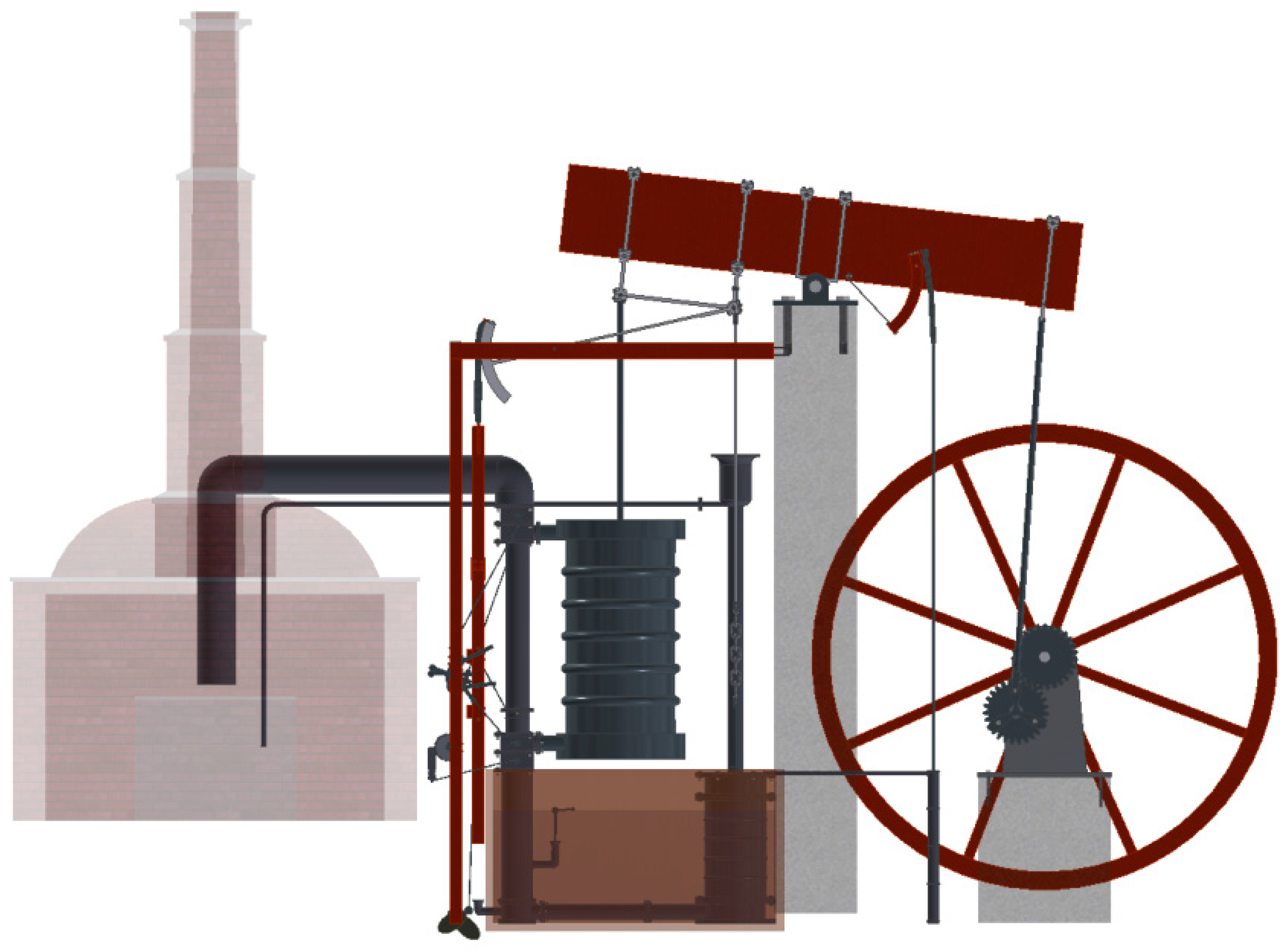
CAE analysis of the Betancourt double-acting steam engine involves high computational requirements since it consists of a large number of parts subjected to various types of stress. For this reason, it is essential to simplify the model that facilitates the analysis (Figure 4). In a similar manner, the mechanism works in several positions and the valves change noticeably the stresses of the different parts of the mechanism according to whether they are open or closed. Finally, for the static analysis of the engine the two positions in which the valves work have been chosen, since a priori one cannot see which of them is going to have greater stresses.
In the first place, it has been decided to remove the water boiler and the brick building that houses it since it is not a structural element of the mechanism and its stresses do not affect the rest of the assembly. However, the pipes that enter and leave the building have been taken into account and it is planned to restrict their movements in order to simulate what we would have if this construction existed.
Secondly, all the elements acting as a foundation have been removed, namely the brick supports of the rocker arm and the inertia flywheel. These elements have been replaced by actions that simulate their behaviour. Specifically, the brick supports have been eliminated and on the contrary, the axes supports that allow the movement of the rocker arm and the inertia flywheel are acted upon. Both supports are defined as articulated supports so that the lower faces do not have any degree of freedom but the axis of the supported element is free to rotate.
Thirdly, the last element that is excluded from the simulation is the water tank where the condenser is submerged and the water that cools it, since both elements do not contribute anything structurally to the mechanism and, on the other hand, water cannot be studied in the static analysis. This element is important when explaining the stresses to which the pipes are subjected due to the pressure and temperature differences that it facilitates but its influence does not go any further.
To conclude this section, it can be said that two different positions have been taken for the study based on the opening of the valves of the steam boxes. Valves B and C, as already explained, allow the passage of water vapor at high pressure and temperature to the upper part of the cylinder chamber or to the lower part. In the first position, when valve B is open and valve C is closed, water vapor passes into the PP pipe and enters the lower part of the cylinder pushing the lower face of the piston and, therefore, causing the rocker arm to rise. In the second position, valve C is open and B closed so that water vapor enters directly into the upper part of the cylinder, pushing the upper face of the piston and therefore lowering the rocker arm. The pressures and the vacuum generated in each of them will be considered when preparing their study.
2.2.2. Assignment of Materials
The next stage is to assign material to each of the elements that make up the assembly. However, the original documents of the invention do not specify the materials, although they do show different parts of the machine made of wood, metal or brick.
From the descriptions of other steam engines of the time, it is known what materials were used in those (e.g., the Watt and Boulton steam engine has been widely studied) and according to those specifications and the simple materials that Betancourt would have access to they have been specified. The materials chosen from the library of materials provided by Autodesk Inventor Professional software have been oak, cast iron for metal parts and brick for structural elements. It should be noted that since the structural elements have been excluded from the analysis for the reasons cited in the previous section, the description of the properties of the brick will be omitted.
Autodesk Inventor Professional establishes specific physical characteristics for each material such as thermal, mechanical, elasticity and breaking properties, among others. Cast iron has an isotropic behaviour and its main physical properties are: Young’s modulus (120,500 MPa), Poisson’s coefficient (0.30), density (7150 kg/m3) and breaking stress (758 MPa). On the other hand, oak wood has physical properties that depend on the direction in which the elements are studied, since it is an orthotropic material. The most favourable conditions occur when the material works in the direction of the grain since, in the other two orthogonal directions, the physical properties are more limited. For this reason, it is important that in the wooden parts the main axes are always those of the direction of the grain. Thus its main physical properties would be: Young’s modulus (9300 MPa), Poisson coefficient (0.0001), density (760 kg/m3) and breaking stress (46.6 MPa).
2.2.3. Boundary Conditions
Once the materials have been assigned and those elements that cannot be subjected to static analysis eliminated from the simulation, the next stage is to define the boundary conditions of the elements that have a support function. Each support can work in a certain way according to the degrees of freedom that define its mobility, so that the definition of this mobility will affect the static analysis of the complete assembly. The supports can be embedded, articulated, mobile or roller. Thus, the software studies the boundary conditions based on the freedom of movement of each component of the support.
In the first place, the elements that have no freedom of movement are defined, these being the surfaces that are screwed into the brick, such as the supports of the different axles (Figure 5a), as well as those that are geometrically inserted into the brick wall (Figure 5b).
Second, the articulations or elements that rotate freely are defined (Figure 6). These components cannot move longitudinally but can rotate, so they have a lesser degree of freedom. Among them are the hinges of the counterweights, the pulleys and the shaft fastenings.
Finally, it would be necessary to define those surfaces of the support that have freedom in only one direction but in the double-acting steam engine there are none.
On the other hand, the boundary conditions do not depend on the two extreme positions that have been proposed for the static analysis but the contacts between the parts change depending on the position to be studied. Autodesk Inventor Professional automatically detects existing contacts between contiguous surfaces as long as the surface is not excessively complex.
2.2.4. Forces Applied
The next step before performing the simulation is to define the forces acting on the invention, since defining each of them correctly is key to quantifying the stresses that affect the steam engine.
The first of the actions that affects the mechanism is gravity. Autodesk Inventor Professional allows the user to define severity using any direction and magnitude. For modelled engine, it is defined as a generic vector of intensity 9.81 m/s2 in the direction of the Z axis and in the negative direction. When defined in a generic way, the software represents the gravity vector applied at the centre of gravity of the engine (Figure 7).
The second action that is going to be characterized is the force that is exerted on the face of the piston of the steam cylinder (Figure 8) and for this the treatise of the English engineer Thomas Tredgold [18] was used, which proposed a method for the calculation of the effect of the strength of the water vapor, as well as its losses and useful work.
According to Tredgold, the quantifiable losses in the steam engine would be:
- (1)
- The force produced by the movement of steam when entering the steam cylinder: 0.007
- (2)
- Cooling in the steam cylinder and in the pipes: 0.016
- (3)
- Piston friction and losses: 0.125
- (4)
- The force necessary to expel the steam: 0.007
- (5)
- The force required to open and close the valves, raise the injection water and overcome the friction of the axles: 0.063
- (6)
- The loss that comes from intercepting the steam before the end of its trajectory: 0.100
- (7)
- The force needed to move the air pump: 0.050
Thus, the sum of all losses is 0.368 and therefore the useful energy would be 0.632.
On the other hand, the steam strength in the boiler was generally 900 mm Hg, the temperature of the non-condensed steam 50 °C and its force 100 mm Hg. So it will be necessary to:
900 × 0.632 – 100 = 468.8 mm Hg = 0.6373 kg/cm2
Since the pressure on the piston is 0.6373 kg/cm2 and its area of 2827.43 cm2, a force will act on it of:
Fpiston = 0.6373 kg/cm2 × 2827.43 cm2 × 9.81 m/s2 = 17,677 kN
Moreover, the force on the piston will be located on the lower face when valve B is open and on the upper face when valve C is open.
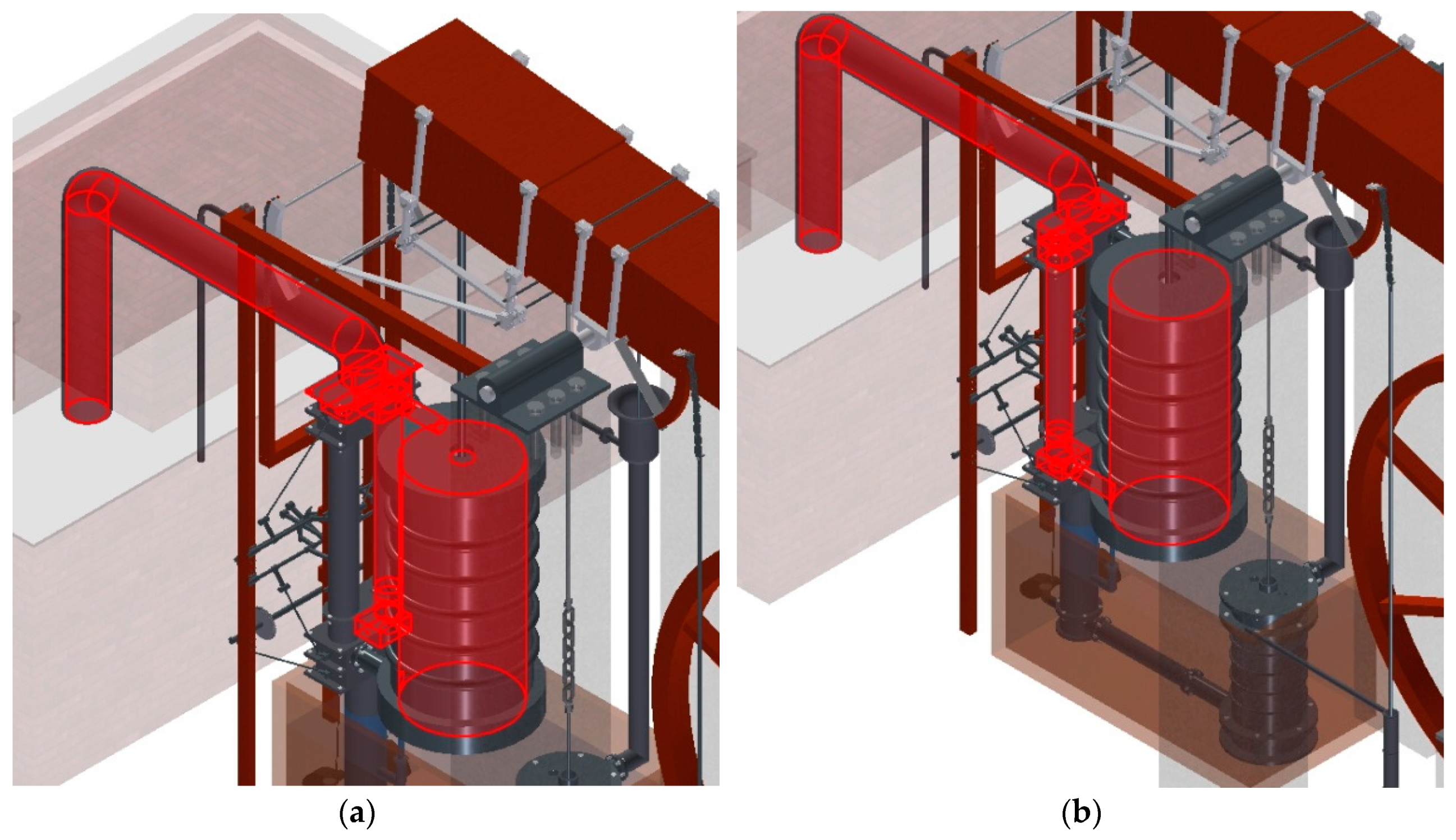
On the other hand, the pressure received by the face of the piston is the same as that received by the pipes directly connected to the boiler (Figure 9). Thus, depending on which valves are open or closed, the pressure in those pipes can be characterized.
When valve B is open, the pipe coming from the boiler, the upper valve box, the PP pipe, the lower valve box, the entrance to the steam cylinder and the lower part of it have a pressure of 0.6373 kg/cm2.
In a similar manner, when valve C is open the upper valve box, the upper entrance of the steam cylinder and the upper part thereof are subjected to a pressure of 0.6373 kg/cm2. The pressure that comes directly from the boiler is called the upper steam pressure. The calculation of the pressure in the lower pipe section with steam at low pressure and temperature (Figure 10) and in the air pump is somewhat more complicated. The air with water vapor that leaves the cylinder does so at a pressure of 0.6373 kg/cm2 but when it reaches the CC’ pipe the water vapor is mixed with a small amount of the water in the tank that is at a lower temperature and higher pressure, causing an immediate condensation of part of the water vapor and therefore producing the vacuum.
Similarly, the pressure outside the pipeline is close to the atmospheric pressure since the pipe is submerged at 0.75 m, so when it is submerged at this depth the external pressure will be:
P = 1000 kg/m3 × 9.81 m/s2 × 0.75 = 7357.5 Pa
This pressure is equivalent to 0.0725 atm which, added to the atmospheric pressure, results in an external pressure of 1.0725 atm. On the other hand, the vacuum pressure starts at 0.2960 atm, so the difference in pressure will be that required by the submerged water pump and piping, that is:
1.0725 − 0.2960 = 0.7765 atm, equivalent to 0.8023 kg/cm2 = 78,678.8 Pa
Finally, the piston of the air pump moves due to the pressure difference between the pipe and atmospheric pressure, so it will be necessary to:
1 − 0.2960 = 0.704 atm, equivalent to 0.727 kg/cm2 = 71,294.3 Pa
2.2.5. Meshing
Discretization is the last stage before executing the stress analysis of the invention and its object is to obtain a mesh that realistically fits its geometry. As a rule, the greater the density of the mesh, the better it adjusts to its geometry. However, smaller elements need a smaller mesh size than larger ones, although this rule admits some exceptions in the case of complex geometries. Similarly, in places where a specific force is applied it is advisable to establish a higher density mesh, because if the geometry of these points is distorted the results suffer important alterations.
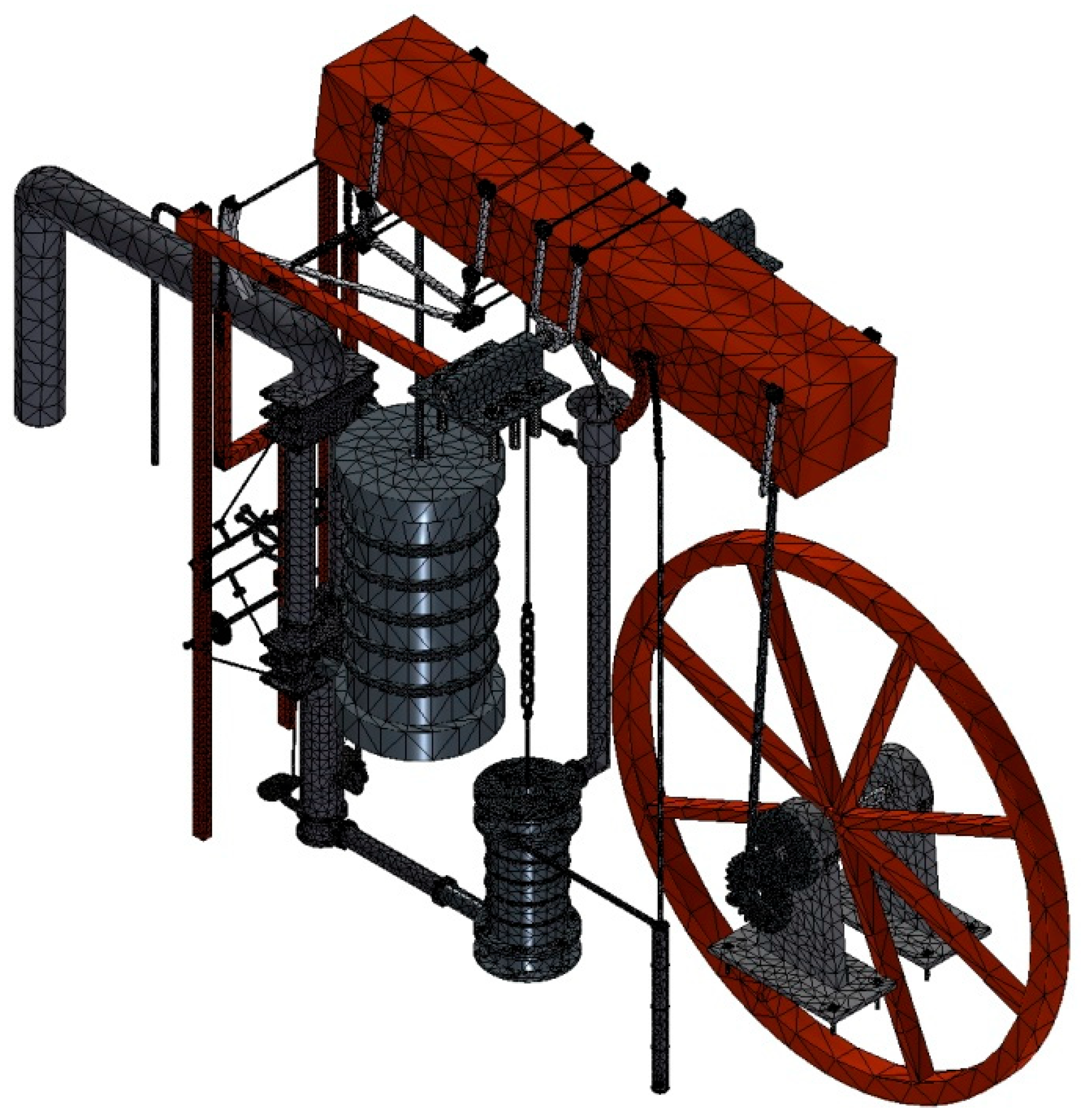
The software used (Autodesk Inventor Professional) presents the option of obtaining the automatic meshing of the part by adjusting some variables in a simple way (Figure 11). By default, this software establishes a mesh formed by tetrahedrons whose average size is 10% of the length of the element, a minimum size of the tetrahedron of 20% of the average size, a maximum variation between tetrahedrons of 1.5 and a maximum angle of rotation of 60°. In the case of the present invention these values are acceptable, although a mesh of higher density will be necessary in the chain links and smaller elements.
In order to modify the automatic discretization it is necessary to refine the mesh on some surfaces, directly indicating the size of the tetrahedron side. This is the procedure with small elements such as valves, valve axles and screws (Figure 12). On the other hand, the software presents a serious drawback with the chain links that appear in some elements of the steam engine since these links, defined individually by sweeping a circular sector on a closed curve, have a toric geometry, meaning that the assembly of these links is carried out by defining a contact between a point of the surface of the upper link and another of the lower one.
In a similar way, the density of the mesh in the zones of contact between links is very large and the contact is established as a single point, so that all the stress is applied to an infinitesimal surface unit, obtaining enormous pressures at these points and therefore distorting the stress results. In order to control and reduce this error at these points the manual mesh control allows the operator to take a mesh density lower than the one established by default, achieving stresses more in line with the real capacity of the chain.
In terms of finite-element analysis with Autodesk Inventor Professional, a convergence criterion has been established since this analysis has been carried out by iterative methods and for a maximum number of ten cycles. Thus, the software compares the result with that of the previous cycle and if that result varies more than 5%, reiterates. However, if the difference is less than 5% the analysis is stopped, adopting the result as definitive. In this study, taking into account computational resources, the analysis used a mesh size of 1,924,288 elements and 3,353,725 nodes.
3. Results and Discussion
Before showing the results of the static analysis of the double-acting steam engine (stress distribution, safety coefficients, deformations and displacements), it is convenient to perform a modal analysis of the engine to determine if there exist any rigid body modes.
Autodesk Inventor Professional performs this simulation by subjecting the structure to vibrations at different frequencies. If the modal frequencies obtained in the analysis are close to 0 Hz then the element to be studied behaves as a mechanism and therefore it would not make sense to perform a static analysis on it.
The eight modal frequencies obtained for the steam engine are: F1: 0.60 Hz, F2: 0.63 Hz, F3: 0.74 Hz, F4: 0.76 Hz, F5: 2.21 Hz, F6: 2.31 Hz, F7: 3.86 Hz and F8: 4.32 Hz. The simulation shows that the first four (slightly lower) frequencies cause displacements in two free counterweights that the invention has whose function is to transmit certain inertia that facilitates the opening and closing of the valves. These counterweights could be excluded in the simulation for a static analysis but this exclusion would affect the solicitation that affects the opening valves of the steam boxes. The dynamism of these elements will therefore be considered so that they do not contaminate interpretation of the results.
The static analysis of the invention has contemplated the study of the two cases indicated above: when the piston of the steam cylinder follows a downward movement and when it moves following an upward movement.
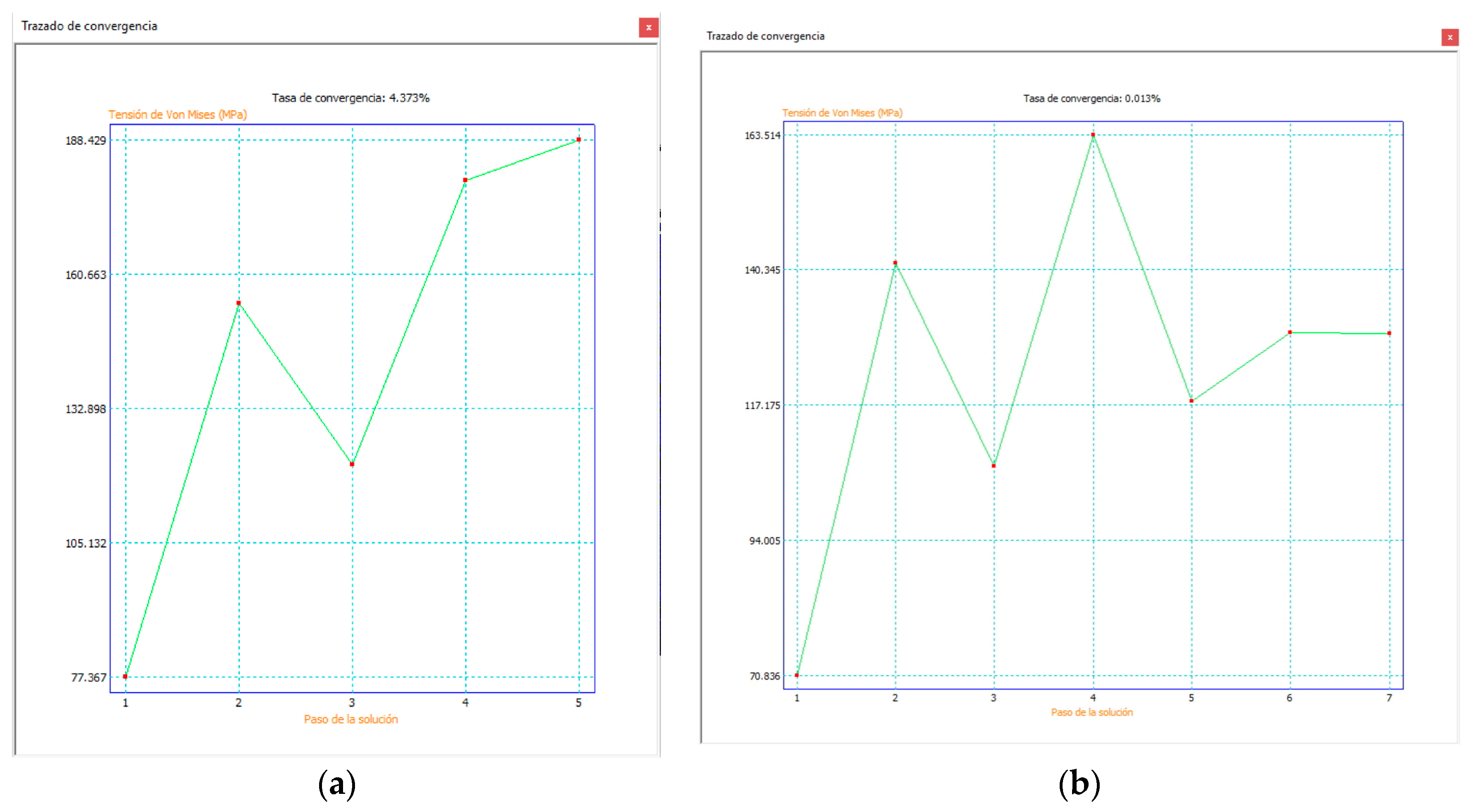
A mesh convergence study has also been performed in order to establish the credibility of the results, since the high stresses are concentrated in very narrow regions of the mechanism. As explained in Section 2.2.5, the discretization of each of the pieces directly affects the results of von Mises stress analysis. The software used allows a refinement of the mesh according to the places where the stress is greater. This process is cyclical since once the regions where the stress is greater are determined, the mesh is refined and the von Mises stress is recalculated. In addition, there are some convergence criteria and in the present study it has been defined that the maximum number of cycles is 10, specifying that when the difference between results is less than 5% the refining process of the mesh is stopped.
Figure 13 shows the convergence curve for the two cases under study. When the piston moves downward, the convergence rate is 4.373% in the fifth iteration (Figure 13a). On the other hand, when the piston moves upwards the convergence rate is lower and therefore more reliable, with a value of 0.013%, although this result is obtained in the seventh iteration (Figure 13b).
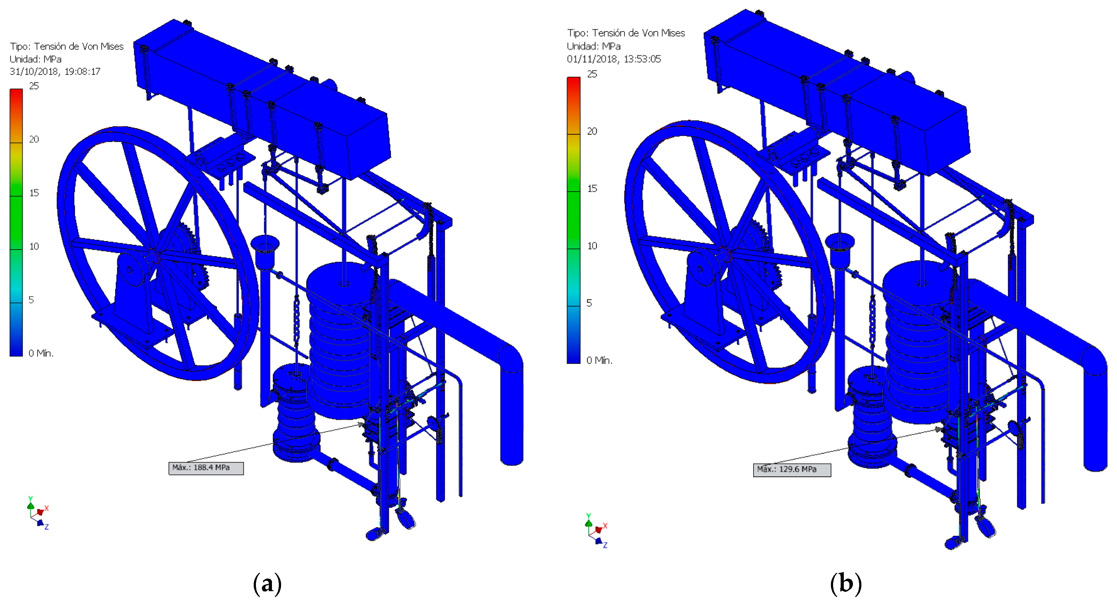
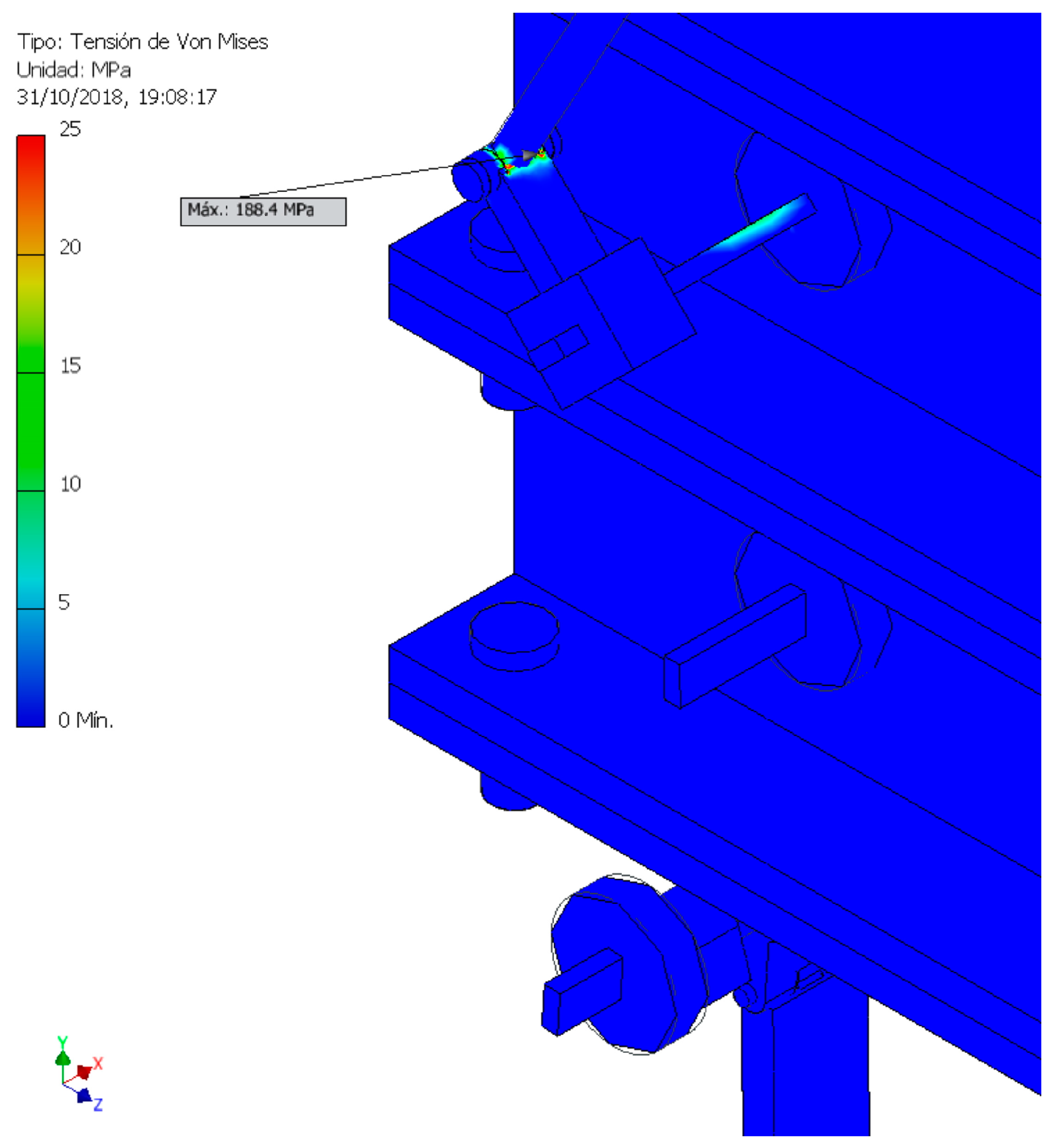
The analysis shows that von Mises stresses are generally low, not reaching 5 MPa (Figure 14), although there are a series of singular points where the stress is higher. This is the case of the opening axle of valve D, one of the valves that diverts water vapor into the piston or into the condensation pipe and occurs when the piston descends, reaching a value of 188.4 MPa (Figure 14a). Also, when the piston rises the maximum stress is located at the same point with a somewhat lower value of 129.6 MPa (Figure 14b). Although these values are high they are not too high, considering the elasticity limit of the material with which the piece is made (cast iron). Figure 15 shows in more detail the point at which the maximum load in the upward direction of the piston is recorded.
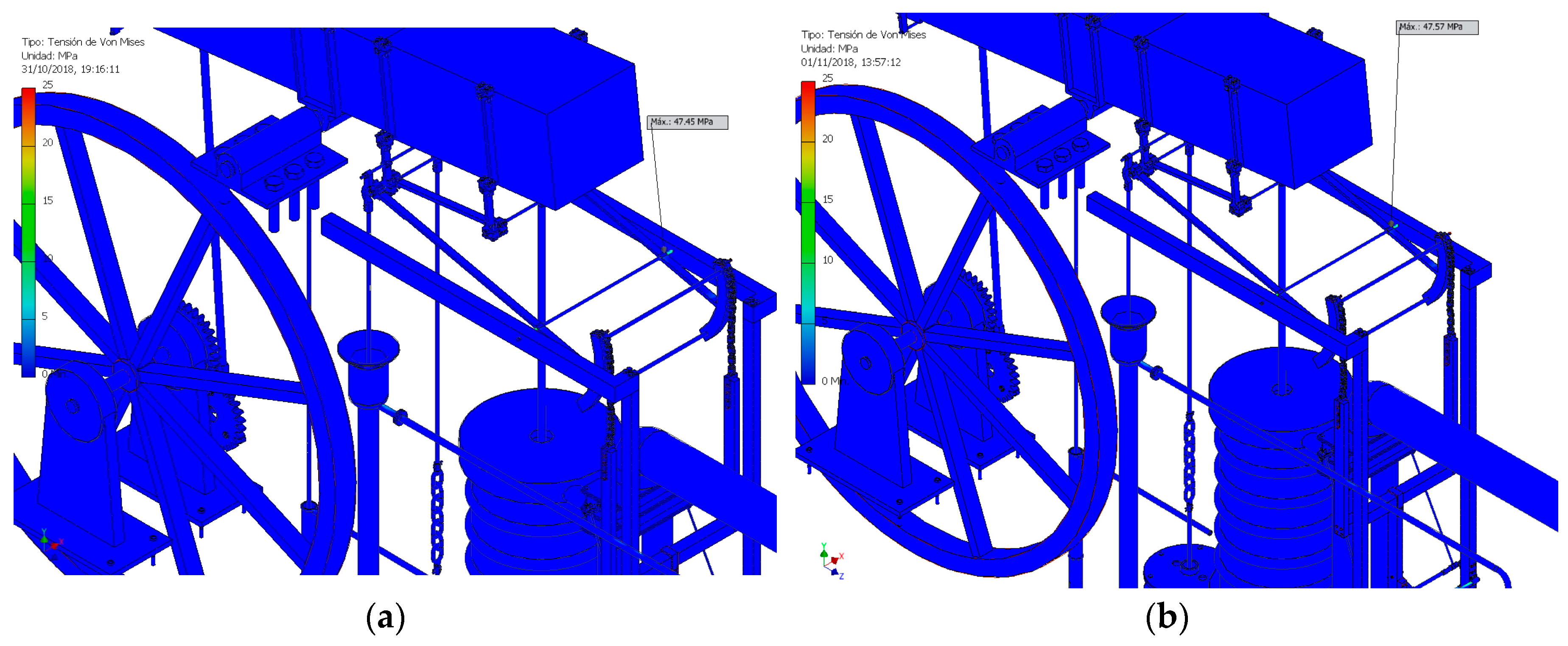
If the parts that regulate the opening of the valves are excluded, the next set of parts subjected to higher stresses are the rods that join the parallelogram to the piston of the steam cylinder. In Figure 16 this greater stress is located specifically in the second rod, just at the point of insertion of the rod with the frame that serves as support. The von Mises stress value for that point is 47.45 MPa (Figure 16a) when the piston of the steam cylinder moves in a downward direction and somewhat higher with a value of 47.57 MPa (Figure 16b), when moving in an ascending direction, which on the other hand makes sense. The values of this second main stress are already relatively low for the metallic materials with which they are made.
Another aspect to be studied is the safety coefficient, which is defined as the relationship between the stress to which a part is subjected and the elasticity limit of the material with which it is manufactured. This parameter shows which elements of a structure work with stresses close to the elastic limit of the material and therefore run the risk of breaking and which elements work below it within a particular safety threshold.
Currently, the parts function with a safety coefficient with values between 2 and 4. Parts that work below 2 are too close to the limit of elasticity and suffer significant fatigue, while if the value is above 4, the pieces work far from that limit and therefore are oversized.
In the time of Agustín de Betancourt, the knowledge that existed on the resistance of materials was not very broad and in addition tests were not realized to determine the limits of elasticity of the materials, the reason why mechanisms were generally quite over-dimensioned. The double-acting steam engine is no exception to this rule.
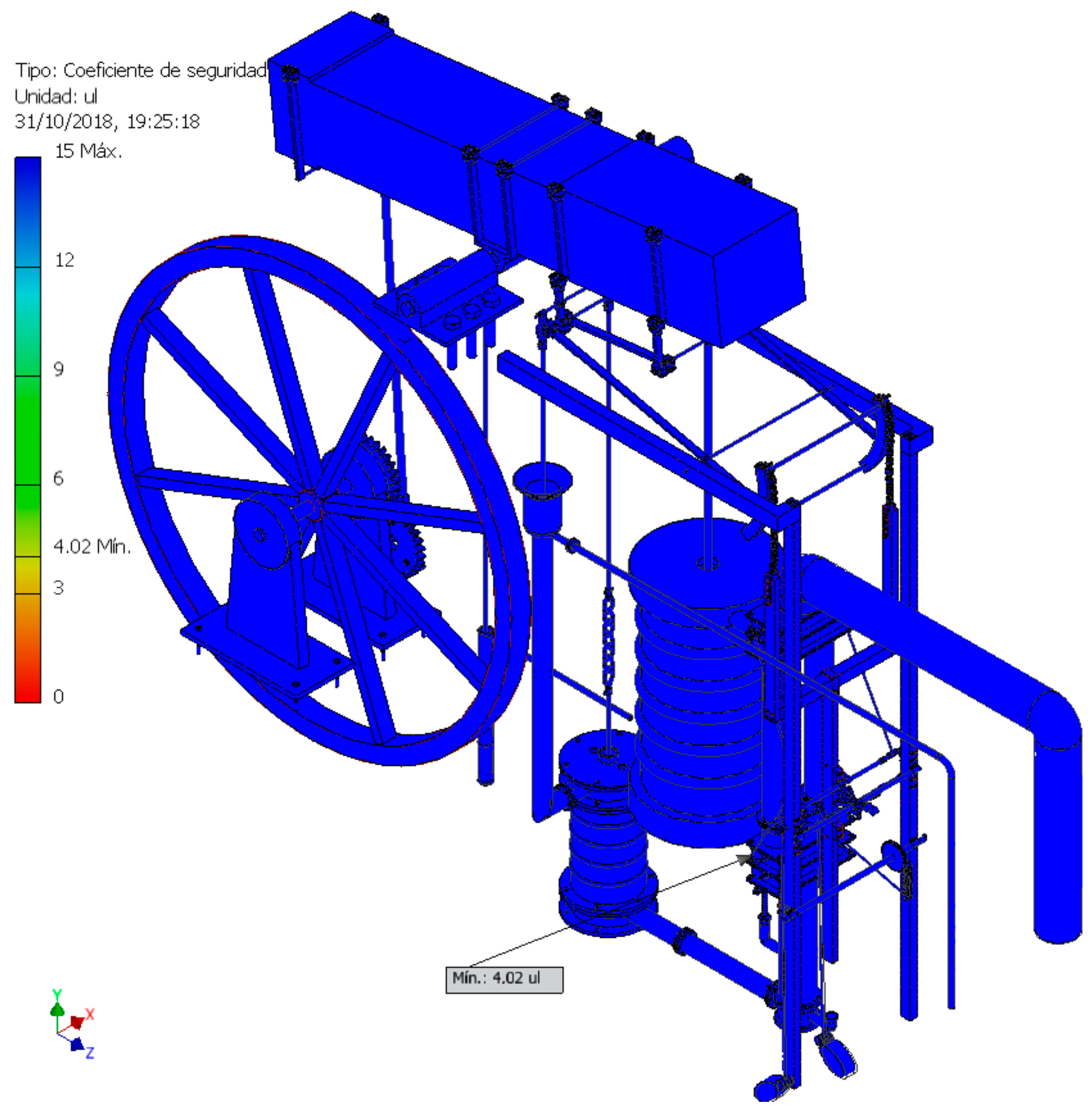
Figure 17 shows the distribution of safety coefficients, it being possible to observe that almost all the elements of the invention have a safety coefficient above 12 and that only a few elements work within a smaller range of values but in any case well over 4.
Furthermore, the point that gives a lower value for the safety coefficient is the opening axle of valve D. The detailed study of the safety coefficient in that axle shows that valve D works with greater stress when the piston of the cylinder is descending and therefore closed and preventing the passage of steam at high pressure to the lower chamber. In this situation the valve axle has a minimum safety coefficient of 4.02 (Figure 18a), above the optimum working values. Similarly, when the valve is open allowing the passage of steam at high pressure the safety coefficient of the valve axle is greater with a value of 5.85 (Figure 18b).
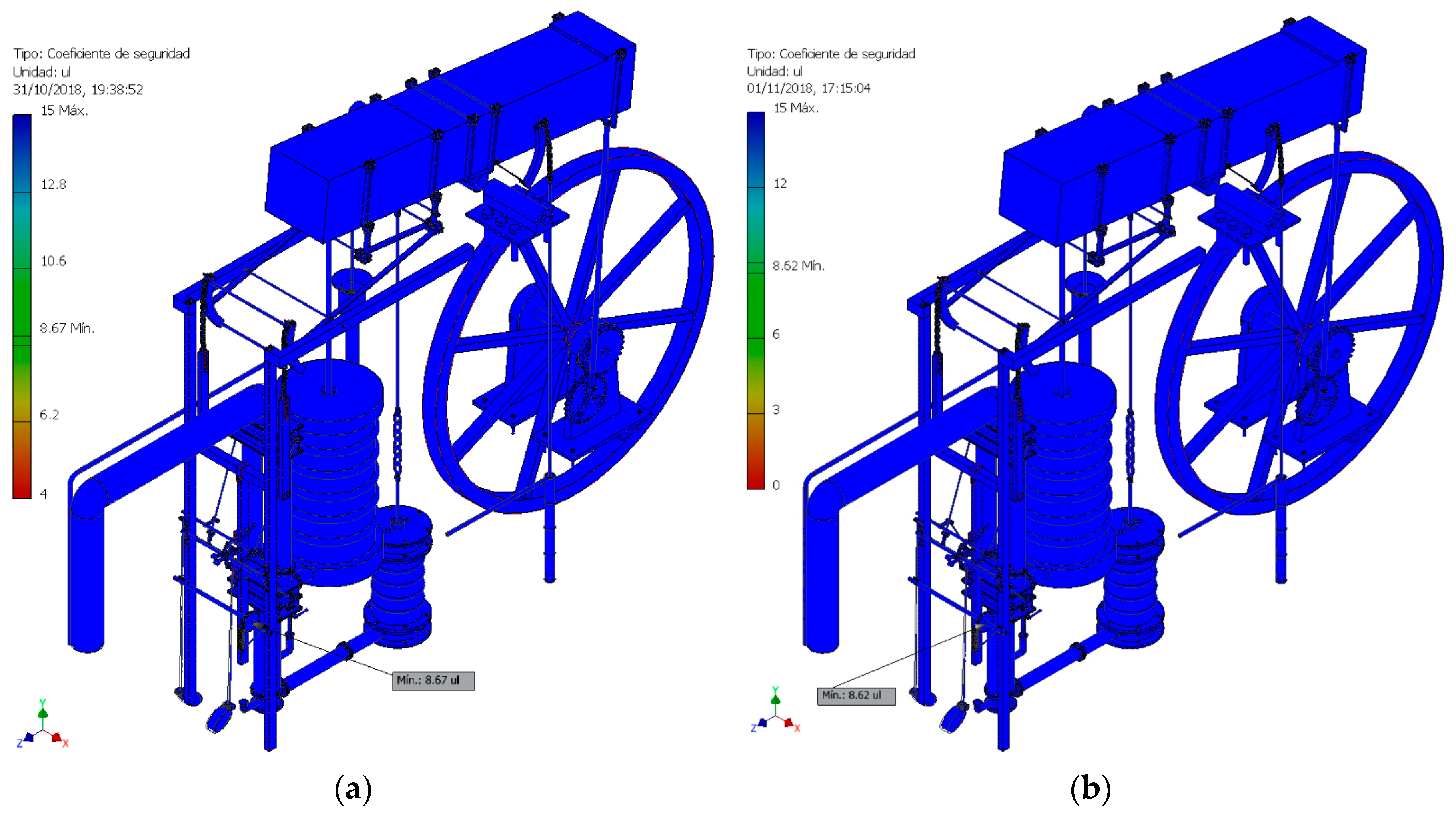
As indicated previously, if a study is performed excluding the valves the element with the lowest safety factor is the engine speed regulator, with a value of 8.67 when the piston of the steam cylinder falls (Figure 19a) and another of 8.62 when it ascends (Figure 19b). Thus, since the rest of the elements have higher coefficients it is completely clear that the engine is largely oversized.
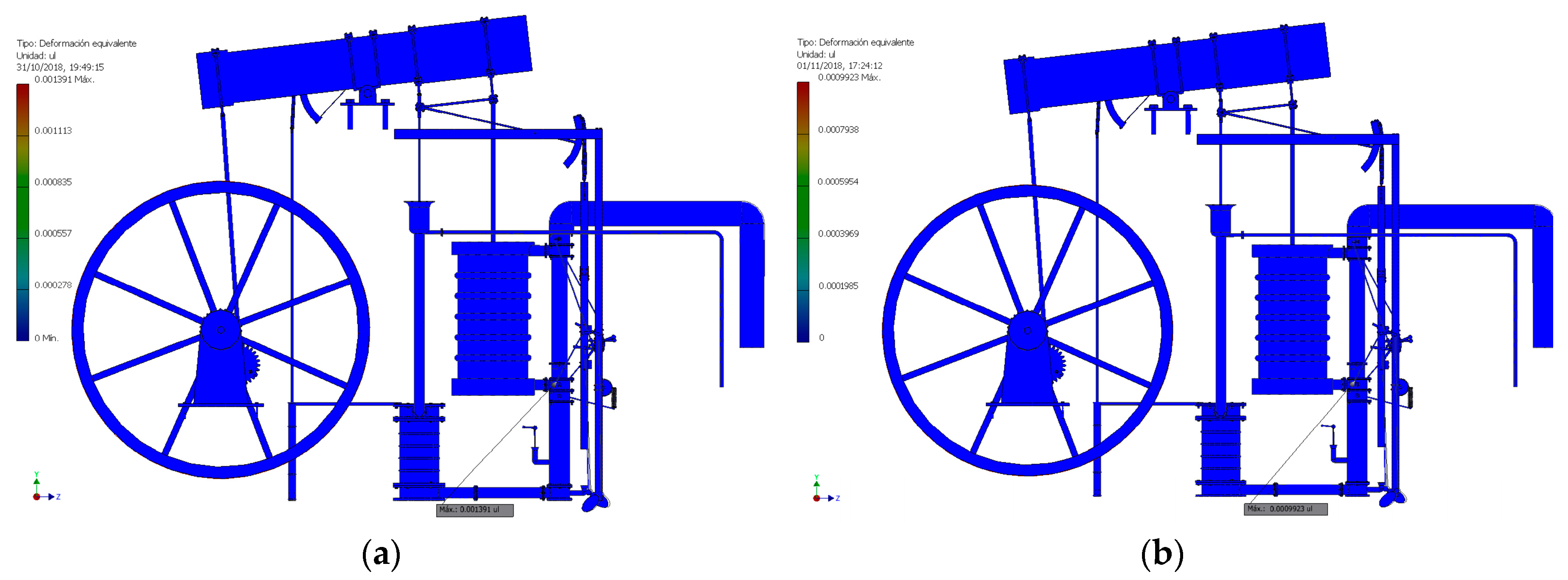
On the other hand, the study of the deformation of the elements that make up a mechanism is important, since even if an element does not work in a range of stresses close to the elastic limit of the material, due to its slenderness it can deform its geometry excessively, compromising the correct contact between these elements. Autodesk Inventor Professional shows the equivalent deformation of each element as a relationship between the deformation of the element and its length. In the present study, the maximum deformation is located in the element that suffers the highest stress, that is the opening axle of valve D. However, its deformation is 0.14% with respect to the size of the element when the piston descends (Figure 20a) and 0.10% when it rises (Figure 20b), so it can be considered negligible.
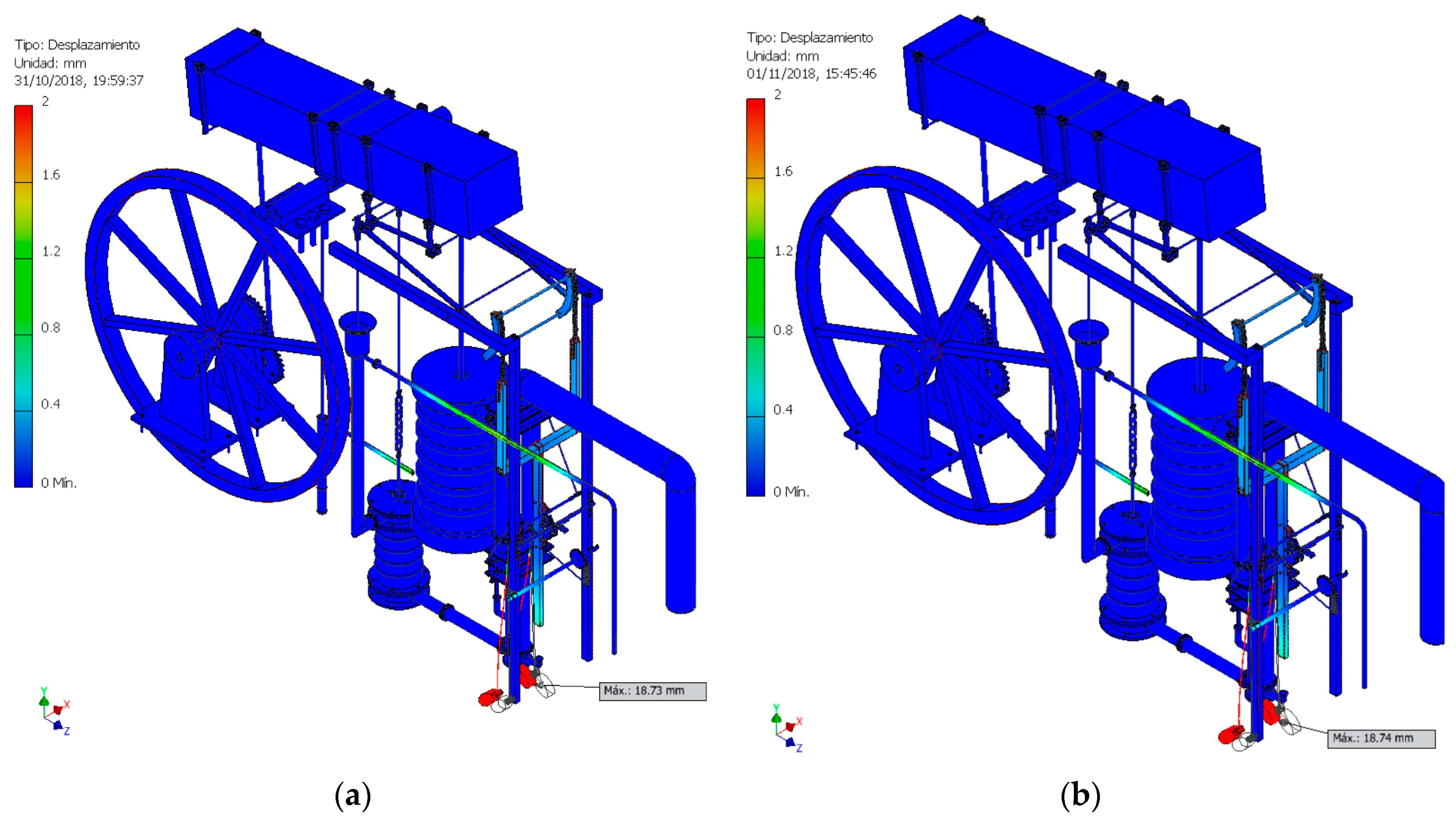
Finally, we should analyse the displacements of some singular elements such as mobile counterweights, which have the highest values. This aspect was indicated previously when carrying out the modal analysis of the invention, since when the counterweights had an inertial function they suffered the greatest displacements.
Thus, when the piston of the steam cylinder moves in a downward direction the counterweight will undergo a displacement of 18.73 mm (Figure 21a) and when it moves in an upward direction of 18.74 mm (Figure 21b). Not in vain, both the material with which the counterweights were made and the elliptical design of the same show that they were designed to bear the wear caused by the continuous movement to which they were subjected.
4. Conclusions
- The article shows the results of the static analysis carried out on the 3D model of the steam engine designed by Agustín de Betancourt and based on James Watt’s double-acting steam engine that he saw working in 1788. For this, CAE techniques have been used thanks to the parametric software Autodesk Inventor Professional.
- The machine presents substantial differences with respect to the model of the Scottish engineer, which makes it a more efficient engine. Its design better transforms the vertical movement of the piston of the steam cylinder into the movement of the rocker arm, using a chain system coupled to the articulated parallelogram invented by Watt in 1784. In addition, the regulating mechanism causes the vacuum generated by the condensation of the water in the pipes to be better used by the engine in the double movement of the piston.
- On the other hand, the results of the static analysis indicate that the double-acting steam engine was completely feasible (it is historically known that Betancourt started one with the Périer brothers in 1790 for a mill in Paris). The study of the von Mises stresses indicates that the point that undergoes a greater tension, the axle of the valve D that regulates the admission of water vapor in the cylinder, presents a value of 188.4 MPa, said value being far from the elastic limit of the material in which it is manufactured (758 MPa). The rest of the pieces work well below this stress value, so it can be said that the choice of materials and dimensions was correct.
- Therefore, according to the results obtained from the safety coefficient it can be said that the structure is a very solid structure, in line with the constructive criteria of the time. The lowest safety coefficient (4.02) is found on the opening axle of valve D, suffering a deformation of 0.14% with respect to its length. Moreover, the maximum displacement (18.74 mm) is found in the mobile counterweights of the engine, mechanisms designed to help in the opening and closing of the valves and designed not to suffer too much wear due to their continuous movement.
- All these data confirm that the invention was correctly sized, although taking into account the values of the safety coefficient of many other elements it could be said that it was clearly oversized. This confirms that practically all the inventions of the time were, due to the fact that there were no resistance tests of materials that would have helped in the design of these inventions.
Author Contributions
Formal analysis (J.I.R.-S. and E.d-.l.M.-D.l.F.); Funding acquisition (J.I.R.-S.); Investigation (J.I.R.-S.); Methodology (J.I.R.-S. and E.D.l.M.-D.l.F.); Project administration (J.I.R.-S.); Supervision (J.I.R.-S.); Validation (E.D.l.M.-D.l.F.); Visualization (J.I.R.-S.); Writing—original draft (J.I.R.-S. and E.D.l.M.-D.l.F.); Writing—review & editing (J.I.R.-S. and E.D.l.M.-D.l.F.).
Funding
This research was funded by the Spanish Ministry of Economic Affairs and Competitiveness (MINECO), under the Spanish Plan of Scientific and Technical Research and Innovation (2013–2016) and European Fund Regional Development (FEDER) under grant number [HAR2015-63503-P].
Acknowledgments
We are very grateful to the Fundación Canaria Orotava de Historia de la Ciencia for permission to use the material of Project Betancourt available at their website. Also, we sincerely appreciate the work of the reviewers of this article.
Conflicts of Interest
The authors declare no conflict of interest.
References
- Cioranescu, A. Agustín de Betancourt: Su obra Técnica y Científica; Instituto de Estudios Canarios: La Laguna de Tenerife, Spain, 1965. (In Spainsh) [Google Scholar]
- Rojas-Sola, J.I.; Galán-Moral, B.; De la Morena-De la Fuente, E. Agustín de Betancourt’s double-acting steam engine: Geometric modeling and virtual reconstruction. Symmetry 2018, 10, 351. [Google Scholar] [CrossRef]
- Ewbank, T. A Descriptive and Historical Account of Hydraulic and Other Machines for Raising Water, Ancient and Modern: With Observations on Various Subjects Connected with Mechanic Arts: Including the Progressive Development of the Steam Engine; D. Appleton and Company: New York, NY, USA, 1842. [Google Scholar]
- García Diego, J.A. Huellas de Agustín de Betancourt en los Archivos Breguet. Anuario de Estudios Atlánticos 1975, 21, 177–221. [Google Scholar]
- Betancourt, A. Mémoire sur une Machine à vapeur à Double Effet; Academy of Sciences: París, France, 1789; Available online: http://fundacionorotava.es/pynakes/lise/betan_doubl_fr_01_1789 (accessed on 2 October 2018).
- Cuadrado-Iglesias, J.I.; Ceccarelli, M. La síntesis de generación de trayectorias en Betancourt. In Proceedings of the XXI Spanish Conference on Mechanical Engineering, Elche, Spain, 9–11 November 2016; pp. 420–427. (In Spanish). [Google Scholar]
- Betancourt, A. Mémoire sur la Force Expansive de la Vapeur de l’eau; Academy of Sciences: París, France, 1790; Available online: http://fundacionorotava.es/pynakes/lise/betan_memoi_fr_01_1790 (accessed on 2 October 2018).
- Payen, M.J. Betancourt et l’introduction en France de la machine à vapeur à double effet. Revue D’histoire des Sciences et de leurs Applications 1967, 20, 187–198. [Google Scholar] [CrossRef]
- Egorova, O.V. The First Steam Machine in Cuba: Little-Known Pages of Agustin de Betancourt’s Work and Life. In Proceedings of the International Symposium on the History of Machines and Mechanisms, Taiwan, China, 11–14 November 2008; pp. 165–174. [Google Scholar]
- Hur, D.J.; Know, S. Fatigue analysis of greenhouse structure under wind load and self-weight. Appl. Sci. 2017, 7, 1274. [Google Scholar] [CrossRef]
- Hsia, S.Y.; Chou, Y.T.; Lu, G.F. Analysis of sheet metal tapping screw fabrication using a finite-element method. Appl. Sci. 2016, 6, 300. [Google Scholar] [CrossRef]
- Proyecto Betancourt. Available online: http://fundacionorotava.es/betancourt (accessed on 2 October 2018).
- Betancourt, A. Explication d’une Machine Destinée à Curer les Ports de mer; Academy of Sciences: París, France, 1808; Available online: http://fundacionorotava.es/pynakes/lise/betan_expli_fr_01_1808 (accessed on 2 October 2018).
- Rojas-Sola, J.I.; De la Morena-de la Fuente, E. Agustín de Betancourt’s Mechanical Dredger in the port of Kronstadt: Analysis through Computer-Aided Engineering. Appl. Sci. 2018, 8, 1338. [Google Scholar] [CrossRef]
- Rojas-Sola, J.I.; De la Morena-de la Fuente, E. Agustín de Betancourt’s piston lock: Analysis of its Construction through Computer-Aided Engineering. Inf. Constr. 2019, 71. [Google Scholar] [CrossRef]
- Rojas-Sola, J.I.; De la Morena-de la Fuente, E. Agustín de Betancourt’s wind machine for draining marshy ground: Analysis of its construction through computer-aided engineering. Inf. Constr. 2018, 70, e236. [Google Scholar] [CrossRef]
- Rojas-Sola, J.I.; De la Morena-de la Fuente, E. Agustín de Betancourt mil for grinding flint: Analysis by computer-aided engineering. Dyna 2018, 93, 165–169. [Google Scholar] [CrossRef]
- Tredgold, T.E. Tratado de las Máquinas de vapor y de su Aplicación a la Navegación, Minas, Manufacturas etc.; Imprenta de D. León Amarita: Madrid, Spain, 1831. (In Spanish) [Google Scholar]
Figure 1.
Isometric view of the double-acting steam engine.

Figure 2.
Detail of the plan of the regulating mechanism of the double-acting steam engine.

Figure 3.
Movement of water vapor in the hydropneumatic system: (a) downward movement of the piston; (b) upward movement of the piston.
Figure 3.
Movement of water vapor in the hydropneumatic system: (a) downward movement of the piston; (b) upward movement of the piston.

Figure 4.
Simplified model of the double-acting steam engine for static analysis.

Figure 5.
Embedded supports: (a) fixed elements (b) inertia flywheel defined as a built-in element to simulate stop situation.
Figure 5.
Embedded supports: (a) fixed elements (b) inertia flywheel defined as a built-in element to simulate stop situation.

Figure 6.
Rotary supports.

Figure 7.
Gravitational force applied at the centre of gravity of the engine.

Figure 8.
Force transmitted by the piston: (a) downward movement and (b) upward movement.

Figure 9.
Pipes with steam at high pressure and temperature: (a) affecting the upper face of the piston and (b) affecting the lower face of the piston.
Figure 9.
Pipes with steam at high pressure and temperature: (a) affecting the upper face of the piston and (b) affecting the lower face of the piston.

Figure 10.
Lower pipe with steam at low pressure and temperature: (a) subjected to atmospheric pressure and (b) subjected to a pressure below atmospheric pressure (by condensation).
Figure 10.
Lower pipe with steam at low pressure and temperature: (a) subjected to atmospheric pressure and (b) subjected to a pressure below atmospheric pressure (by condensation).

Figure 11.
Automatic mesh obtained from the double-acting steam engine.

Figure 12.
Refinement of the mesh in areas of complex geometry.

Figure 13.
Convergence curve: (a) downward movement and (b) upward movement.

Figure 14.
Von Mises stress distribution: (a) downward movement and (b) upward movement.

Figure 15.
Location of the point where the von Mises stress is maximum.

Figure 16.
Location of the second highest von Mises stress: (a) downward movement and (b) upward movement.
Figure 16.
Location of the second highest von Mises stress: (a) downward movement and (b) upward movement.

Figure 17.
Distribution of safety coefficients.

Figure 18.
Location of the lowest safety coefficient: (a) downward movement and (b) upward movement.
Figure 18.
Location of the lowest safety coefficient: (a) downward movement and (b) upward movement.

Figure 19.
Second lowest safety coefficient: (a) downward movement and (b) upward movement.

Figure 20.
Equivalent deformations: (a) downward movement and (b) upward movement.

Figure 21.
Displacements: (a) downward movement and (b) upward movement.

© 2018 by the authors. Licensee MDPI, Basel, Switzerland. This article is an open access article distributed under the terms and conditions of the Creative Commons Attribution (CC BY) license (http://creativecommons.org/licenses/by/4.0/).
Share and Cite
MDPI and ACS Style
Rojas-Sola, J.I.; De la Morena-De la Fuente, E. Agustín de Betancourt’s Double-Acting Steam Engine: Analysis through Computer-Aided Engineering. Appl. Sci. 2018, 8, 2309. https://0-doi-org.brum.beds.ac.uk/10.3390/app8112309
AMA Style
Rojas-Sola JI, De la Morena-De la Fuente E. Agustín de Betancourt’s Double-Acting Steam Engine: Analysis through Computer-Aided Engineering. Applied Sciences. 2018; 8(11):2309. https://0-doi-org.brum.beds.ac.uk/10.3390/app8112309
Chicago/Turabian StyleRojas-Sola, José Ignacio, and Eduardo De la Morena-De la Fuente. 2018. "Agustín de Betancourt’s Double-Acting Steam Engine: Analysis through Computer-Aided Engineering" Applied Sciences 8, no. 11: 2309. https://0-doi-org.brum.beds.ac.uk/10.3390/app8112309
Note that from the first issue of 2016, this journal uses article numbers instead of page numbers. See further details here.