Article

Sodium Acetate Orientated Hollow/Mesoporous Magnetite Nanoparticles: Facile Synthesis, Characterization and Formation Mechanism

School of Life Science and Chemistry, Hunan University of Technology, Zhuzhou 412007, China
*
Author to whom correspondence should be addressed.
These authors contributed equally to the work.
Submission received: 22 January 2018 / Revised: 7 February 2018 / Accepted: 9 February 2018 / Published: 16 February 2018
(This article belongs to the Section Chemical and Molecular Sciences)

Abstract

:

Featured Application

Magnetite nanoparticles with controllable sizes and spatial structures are promising to be applied in magnetic fluid, high performance batteries, magnetic targeting and imaging, and drug delivery systems related biomedical field.

Abstract

Monodispersed magnetite (Fe3O4) nanospheres with hollow or porous interior structures were synthesized by a facile one-pot solvothermal route. The facile synthetic process was carried out by using iron (III) chloride hexahydrate (FeCl3·6H2O) as only ferric ion resource, and anhydrous sodium acetate (NaAc) as structure-directing agent in an ethylene glycol solution without any templates or surfactants involved. The sizes, morphologies, crystal structures and magnetic properties of hollow Fe3O4 NPs are characterized via Scanning electron microscopy (SEM), Transmission electron microscopy (TEM), X-ray powder diffraction (XRD) and Vibrating sample magnetometer (VSM) techniques. The influences of reaction time, molar ratio of reactants on the morphologies and magnetic performances are also investigated. The different morphologies of magnetite (Fe3O4) particles were presented with tunable size ranging from 85 to 250 nm and controllable structures including porous and hollow construction by using different amount of anhydrous NaAc. A plausible mechanism based on sodium acetate assistant local Ostwald ripening is proposed for acquiring the tailorable morphology and magnetic performance. Such a design conception of anhydrous NaAc assisted Ostwald ripening applied here is a significant alternative for synthesizing hollow magnetic particles, and it could elucidate some light to understand and construct other novel hollow/mesoporous nanostructures.

1. Introduction

Since nanotechnology have been rapidly developed in recent decades, nanomaterials with high performances attract a lot of attentions in various applications. Recently, hollow nanoparticles (NPs) are synthesized successfully for practical application, such as catalysis, lithium ion battery and biomedicine because the large surface area and hollow/porous structures are facilitated to loading more drugs or increasing more active reaction sites. Especially, the hollow magnetic (Fe3O4) NPs show more potentiality in multi-functional application, including fundamental size-dependent magnetism/optoelectronics and targeted drug delivery application due to their low toxicity [1,2,3,4,5].
Various methods, including hard template method [6,7,8], soft template method [9], free template method [10,11] and sacrificial template method [12,13,14,15] are employed for synthesis of hollow iron oxide NPs. In particular, as for the hard template method, the greatest merit of it is that the grain size of the hollow structure is controllable. However, these steps are cumbersome and the hollow NPs are easy to collapse after removing the template. Comparatively, the soft template method is a low-cost technique for synthesis of hollow Fe3O4. However, the large particle size could restrict its practical application. Moreover, hollow Fe3O4 with small size could be precisely synthesized by sacrificial template method. Nanoscale Kirkendall effect is a typical mechanism for explaining the formation of hollow Fe3O4, which could be exploited and extended for synthesis with metal-containing starting materials. Additionally, the free template method is a common method for preparing the hollow nanostructure, it is easy to operate and to prepare the NPs with uniform size distribution [16,17,18]. This method could also be used for synthesis of hollow/mesoporous Fe3O4 NPs. But the disadvantage of this method is that the hollow diameter cannot be precisely controlled by artificial regulation.
Hydrothermal route is a typical free template method, and during hydrothermal process, the iron oxide nanoparticle with different morphology and particle sizes could be synthesized by changing the structure direct agents [19,20,21,22]. For example, Lin X. and co-workers [23] prepared a variety of hollow magnetic NPs by a simple hydrothermal method. Ethylene glycol was used as solvent and reducing agent, and a variety of ammonium salts were added as structure-directing agent for synthesis of the hollow Fe3O4 NPs with various morphologies. Moreover, in our previous work [24,25], the monodisperse Fe3O4 hollow/mesoporous spheres were synthesized by using ammonium acetate (NH4Ac) and ammonium bicarbonate (NH4HCO3) as a structural guide agent. The produced NH3 and CO2 bubbles could be responsible for hollow and mesoporous formation, respectively. After regulating the ratio of NH4Ac and NH4HCO3, the Fe3O4 NPs with different morphologies were obtained correspondingly.
However, as most literatures reported, the particle-sizes of hollow Fe3O4 NPs are always larger than 200 nm via hydrothermal method, and the intensity of saturation magnetization (Ms) is not satisfied for targeting applications. As a result, an alternative method to fabricate size-controllable magnetite NPs with hollow/mesoporous structure remains as a currently lasting challenge. Herein, hollow/mesoporous Fe3O4 NPs with different particle-sizes are synthesized by facile hydrothermal method. Iron (III) chloride hexahydrate (FeCl3·6H2O) is used as the only ferric ion resource, and anhydrous sodium acetate (NaAc) is acted as structure-directing agent to prepare hollow or mesoporous magnetite (Fe3O4) NPs in ethylene glycol solution under 200 °C. The sizes, morphologies, crystal structures and magnetic properties of Fe3O4 NPs are carefully characterized by SEM, TEM, XRD and VSM. The influences of reaction time, molar ratio of reactants on the morphologies and magnetic performances are also investigated. Finally, the formation mechanism of these Fe3O4 NPs is proposed.

2. Experimental Section

2.1. Material and Methods

Ferric chloride hexahydrate (FeCl3·6H2O), anhydrous sodium acetate (NaAc), ethylene glycol (EG), ethanol (99.7%) and other chemical reagents with analytical grade were purchased from Sinopharm Chemical Reagent Co., Ltd. (Shanghai, China). Millipore water (18.2 MΩ cm at 25 °C) was used throughout all experiments. Field emission Transmission electron microscopy (TEM) images were taken using a Hitachi JEM-1230 (JEOL, Tokyo, Japan) transmission electron microscope at an accelerating voltage of 200 kV. Scanning electron microscopy (SEM) images were obtained using a Hitachi S-3000 (Hitachi, Tokyo, Japan). X-ray powder diffraction (XRD) measurements were performed on a Bruker Advanced-D8 (Bruker AXS GmbH, Karlsruhe, Germany) Nanoparticle size analyzer patterns were taken at Malvern Zetasizer Nano S90 (Malvern, Worcestershire, UK), The HH-15 vibrating sample magnetometer (VSM) (Nanjing University Instrument Factory, Nanjing Institute of Electronics Ding one hundred, Nanjing, Jiangsu, China) was used in the magnetic measurement. The stopwatch timer (Tianfu PC2360, Zhejiang winds sporting goods factory, Yiwu City, Zhejiang, China) was measured the reaction time.

2.2. Synthesis of Hollow/Mesoporous Fe3O4 NPs

A certain amount of FeCl3·6H2O was dissolved in 40 mL of EG to form a clear solution, followed by adding a certain amount of anhydrous NaAc (The specific parameters were presented in Table 1.) The mixture was vigorously mixed by ultrasonication for formation of a homogeneous solution. Then, the solution was transferred into a Teflon-lined stainless steel autoclave (100 mL capacity) for hydrothermal treatment at 200 °C for 5–20 h. After the autoclave was allowed to cool down to room temperature, the precipitate was collected by magnetic separation and washed by water and ethanol for several times under sonication. Finally, the products are dried under vacuum at room temperature.

3. Result and Discussion

The influences of reaction time, molar ratio of FeCl3·6H2O and anhydrous NaAc on the sizes, morphologies, crystal structures and magnetic properties of these hollow or mesoporous Fe3O4 NPs are carefully investigated by SEM, TEM, XRD and VSM techniques.

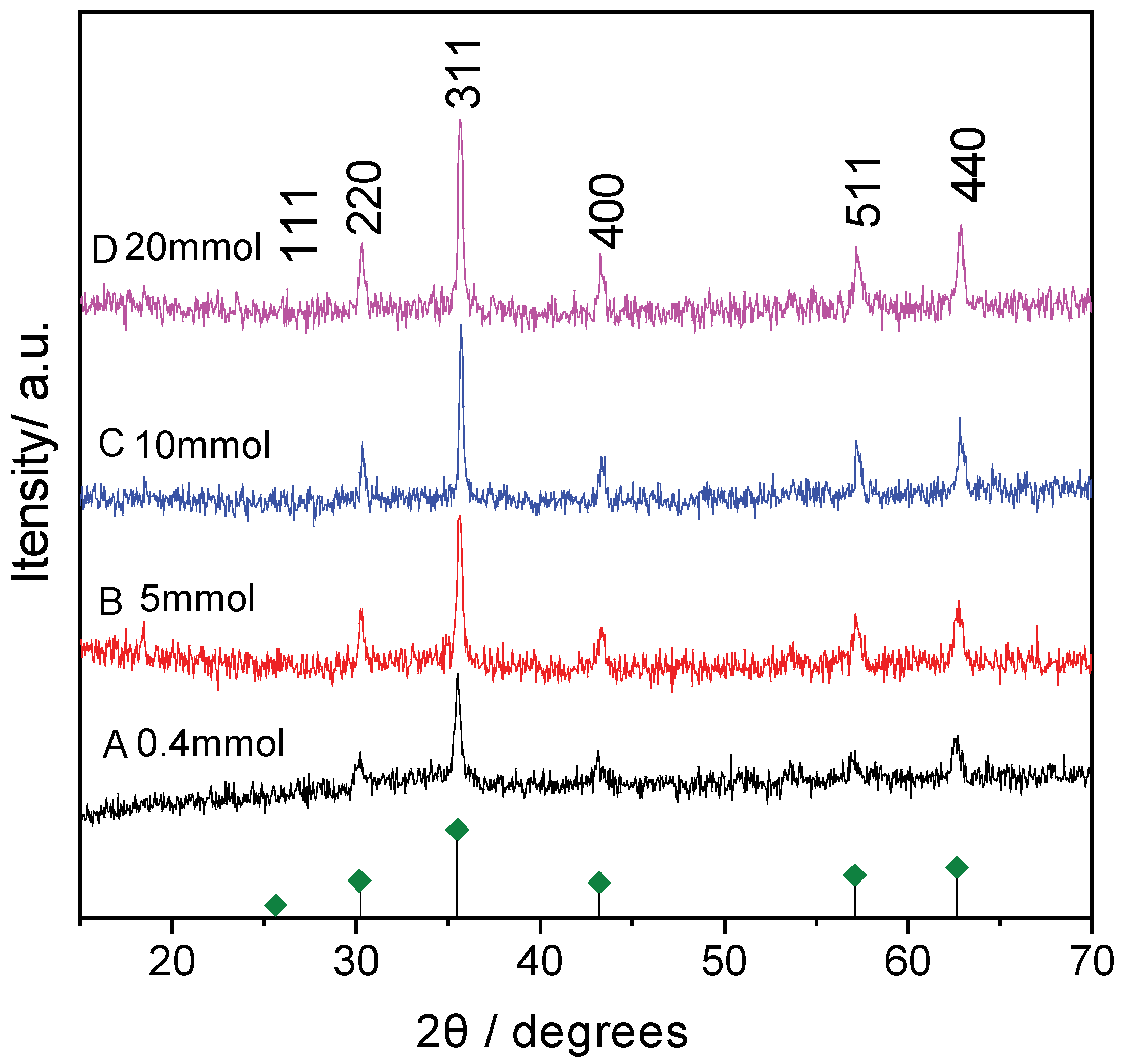
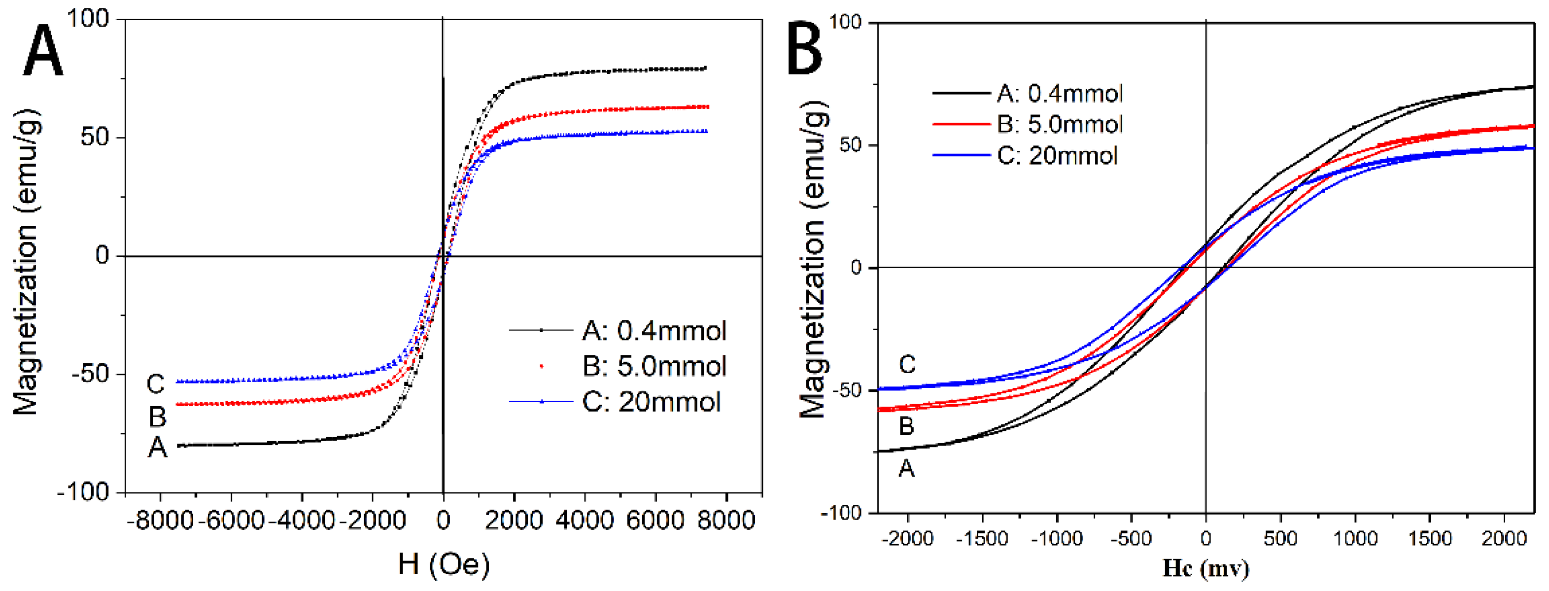
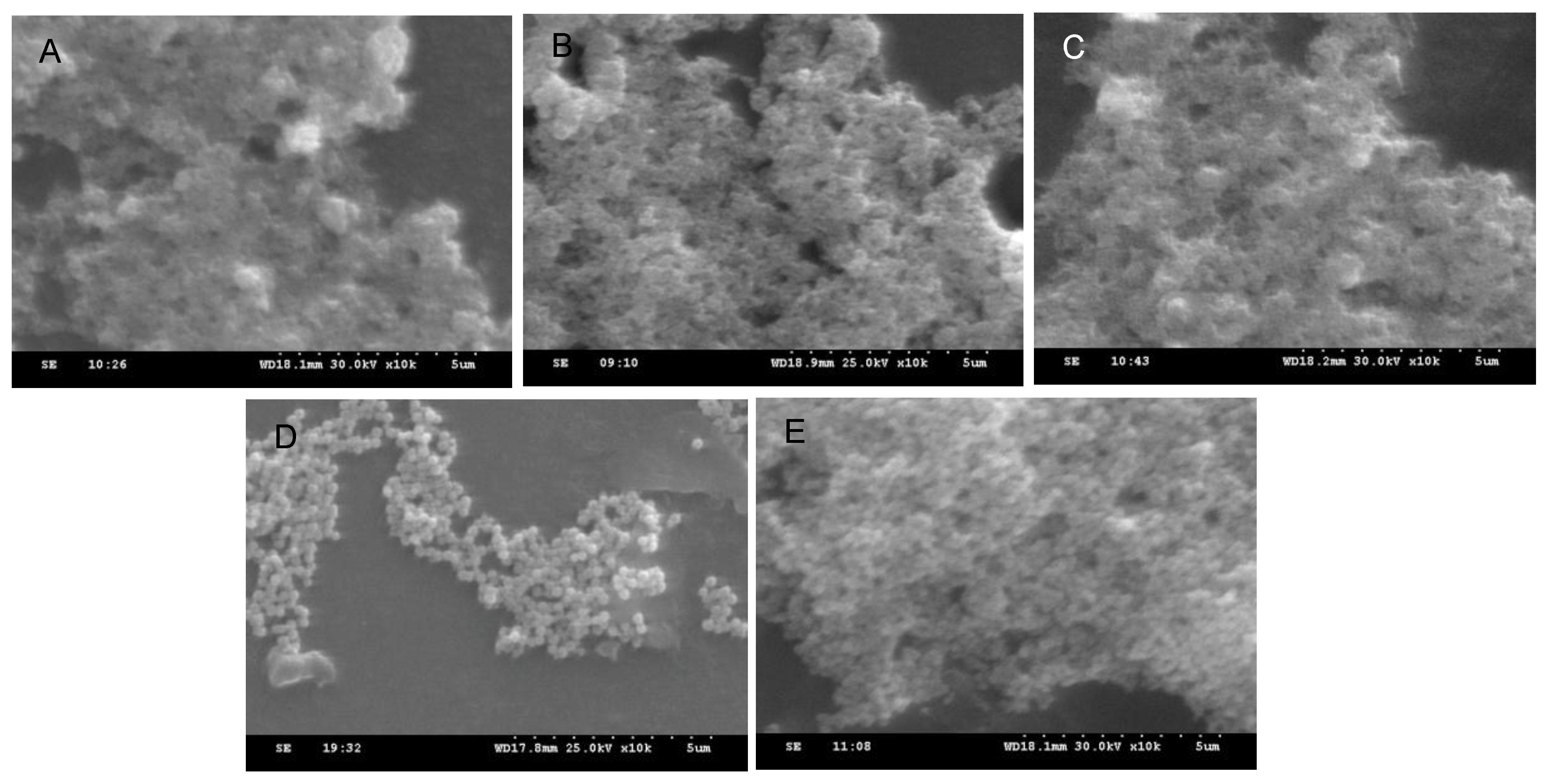
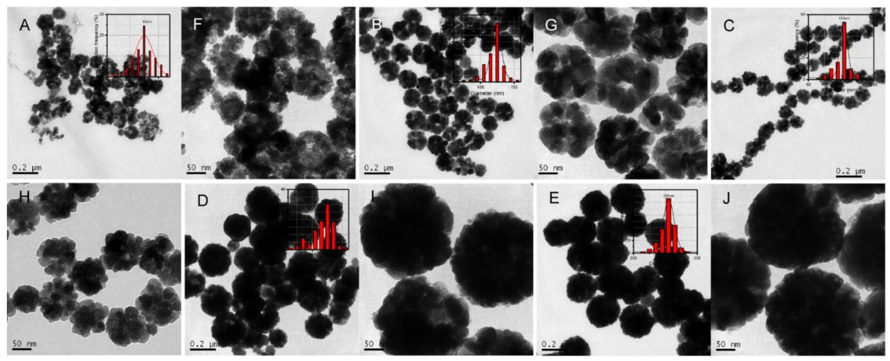
3.1. Morphology, Crystal Structure, and Magnetic Property of Fe3O4 NPs with Different Amount of FeCl3·6H2O

In this section, four experimental groups are carried out for investigating the influence of FeCl3·6H2O on the morphology of Fe3O4 NPs. By only changing the initial amount of FeCl3·6H2O (0.4 mmol (S1), 5 mmol (S2), 10 mmol (S3) and 20 mmol (S4)), the Fe3O4 NPs with different performances are obtained (The specific parameters are presented in Table 1). Firstly, the SEM images of as-synthesized Fe3O4 NPs are presented in Figure 1. As shown in the SEM images, the mean particle size of Fe3O4 NPs (S1) are smaller than 100 nm when 0.4 mmol of FeCl3·6H2O was added (Figure 1A). The mean particle size of Fe3O4 NPs (S2) is increasing to 200 nm when the amount of FeCl3·6H2O is 5 mmol. (Figure 1B), and the dispersity is better than these NPs in Figure 1A. As shown in Figure 1C, nearly monodispersed Fe3O4 NPs (S3) with mean particle sizes between 100 and 200 nm are obtained when the FeCl3·6H2O increase to 10 mmol. The SEM images in Figure 1D indicate that the average size of as prepared Fe3O4 NPs (S4) is less than 100 nm.
The TEM images and corresponding particle size distribution of the as-prepared Fe3O4 NPs are presented in Figure 2. The S1 showed spherical morphology with average particle size of 101 nm (Figure 2A,E). But the size distribution is wide, and the hollow structure is not obvious. After increasing the amount of FeCl3·6H2O to 5 mmol, the hollow structure of as-obtained Fe3O4 NPs (S2) is more apparent, and the mean particle size is 222 nm (Figure 2B,F). The average particles size of S3 is 116 nm, and the internal mesoporous structure could be observed in Figure 2C,G. Moreover, with the increasing of FeCl3·6H2O, the flower-like Fe3O4 NPs without hollow and mesoporous structure are presented in Figure 2D,H. These results indicated that the morphology could be influenced by the amount of FeCl3·6H2O greatly.
Moreover, the XRD patterns of these Fe3O4 (S1–S4) are shown in Figure 3. The XRD is conducted to confirm the crystal structure and composition of these samples. As shown in Figure 3, the peaks at 2θ = 25.7°, 30.4°, 35.7°, 43.2°, 57.3° and 62.8° are evidently observed in these curves, and these peaks could index to the crystal planes of (111), (220), (311), (400), (511) and (440) of Fe3O4 (JCPDS PDF: 01-1111, α = 8.393 Å), respectively. There are no other impurity peaks in these curves, it indicates that the as-prepared Fe3O4 NPs possess inverse spinel phase. Meanwhile, the intensities of S1–S4 is increasing gradually. It indicates that the FeCl3·6H2O could influence the crystal performance of as-prepared Fe3O4 NPs.
Finally, the magnetic performances of as-obtained Fe3O4 NPs are investigated by VSM. The magnetization curves of the Fe3O4 NPs are shown in Figure 4A,B. The magnetic saturation Ms values of the as-obtained Fe3O4 NPs in Figure 4A (a: S1, b: S2, c: S4) are 79.80, 62.50 and 53.43 emu·g−1, respectively. The present coercivity (Hc) values in Figure 4B are about 100 Oe (A/m), indicating a very good soft magnetic property. Obviously, the Ms values of Fe3O4 NPs increase gradually with the decreasing of FeCl3·6H2O. Figure 3C shows the photographs of the suspension of Fe3O4 NPs with an external magnet application. The Fe3O4 NPs can be easily dispersed in ethyl alcohol solution to form a black suspension, and it could also be drawn from the solution to the sidewall of the vial by an external magnetic field. The aggregate NPs could further re-dispersed in solution by removing the external field and slightly shaking.

3.2. Morphology, Crystal Structure, and Magnetic Property of Fe3O4 NPs with Different Amount of NaAc

The amount of anhydrous NaAc could be the another factor to influence the morphologies and performances of Fe3O4 NPs. Five experimental groups with different anhydrous NaAc adding (5 mmol (S5), 10 mmol (S6), 20 mmol (S7), 40 mmol (S8), 60 mmol (S9)) are carried out for discussion the effect. Other synthetic conditions in each of these experiments are kept the same as those in the typical experiment, and the specific parameters are presented in Table 1. In the first place, the SEM images of S5–S9 are presented in Figure 5. As shown in these SEM images, the floccule is observed when 5 mmol NaAc is added. It indicates that these Fe3O4 are presented with smaller particle sizes. With increasing the NaAc to 10 mmol, the particle sizes of the Fe3O4 samples are increased obviously with better dispersity, which is observed in Figure 5B. Moreover, nearly monodispersed Fe3O4 NPs with particle sizes between 100 and 200 nm are obtained when the NaAc is increased to 20 mmol (Figure 5C). While the particle sizes of S8 and S9 become larger than S5–S7. These as-prepared Fe3O4 NPs show better dispersity and homogeneity.
Additionally, these samples are further characterized by TEM, and these TEM images and the corresponding particle size distribution of the as-prepared Fe3O4 particles are presented in Figure 6. The homogeneity of S5 is very poor when 5 mmol of anhydrous NaAc was added, and the mean particle size of these Fe3O4 NPs (S5) is 85 nm with various morphologies (Figure 6A,F). After 10 mmol of anhydrous NaAc adding, the Fe3O4 (S6) NPs in Figure 6B,G show the unconspicuous hollow structures with uniform size distribution. The average particle size is 122 nm. When increasing the NaAc to 20 mmol, the flower-like Fe3O4 NPs (S7) with average particle size of 103 nm are presented in Figure 6C,H. The mesoporous structure of these Fe3O4 NPs become more apparent. However, the evident hollow structures could be found with the increasing of anhydrous NaAc. The S8 show a better hollow structure in Figure 6D,I with mean particle size of 222 nm, and their surface is smooth. S9 with mean particle size of 256 nm are presented in Figure 6E,J had a similar internal structure.
Moreover, the XRD patterns of Fe3O4 NPs (S5–S9) with different amount of NaAc are shown in Figure 7. The XRD is conducted to confirm the crystal structure and composition of the as-synthesized Fe3O4 NPs. As shown in Figure 7, these peaks at 2θ = 25.7°, 30.4°, 357°, 43.2°, 57.3° and 62.8° could be evidently observed in all curves, which are corresponding to the crystal planes of (111), (220), (311), (400), (511), (440) in Fe3O4 (JCPDS No. 01-1111, α = 8.393 Å) Only these peaks of Fe3O4 NPs are observed, it indicates that the Fe3O4 NPs show good crystallinity with inverse spinel phase. However, the diffraction peaks of S5 are significantly lower than other samples, indicating the lower crystallization property of S5. These results demonstrate that NaAc show a distinctly influence on the crystallinity of Fe3O4 NPs. S6 show the best crystallization property and smaller particle size, which is facilitated to magnetic targeting drug delivery.
The magnetization curves of the Fe3O4 NPs (S6, S8 and S9) are shown in Figure 8. The magnetic saturation Ms values of the obtained Fe3O4 NPs in Figure 8A (a: S6, b: S8, c: S9) are 49.64, 62.50 and 52.28 emu·g−1, respectively. The present coercivity Hc values in Figure 8B are less than 150 Oe (A/m), it indicates that these NPs show a good soft magnetic property. Figure 8C shows the photographs of the suspension of Fe3O4 NPs (S6, S8 and S9) with an external magnet. The Fe3O4 NPs can be easily dispersed in ethyl alcohol solution to form a black suspension in 1 min, and it could also be drawn from the solution to the sidewall of the vial by an external magnetic field. The aggregate NPs could further re-dispersed in solution by removing the external field and slightly shaking.

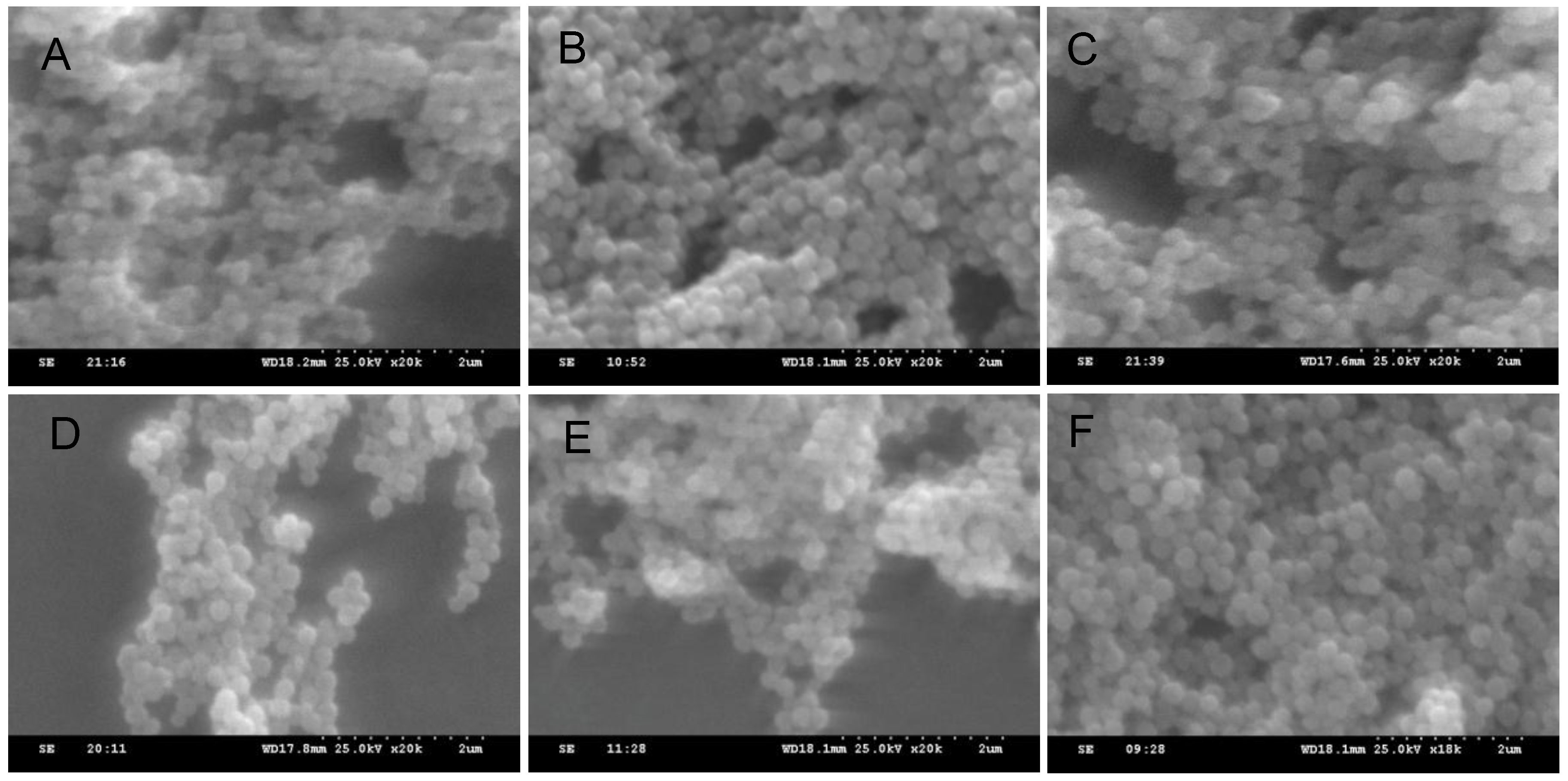
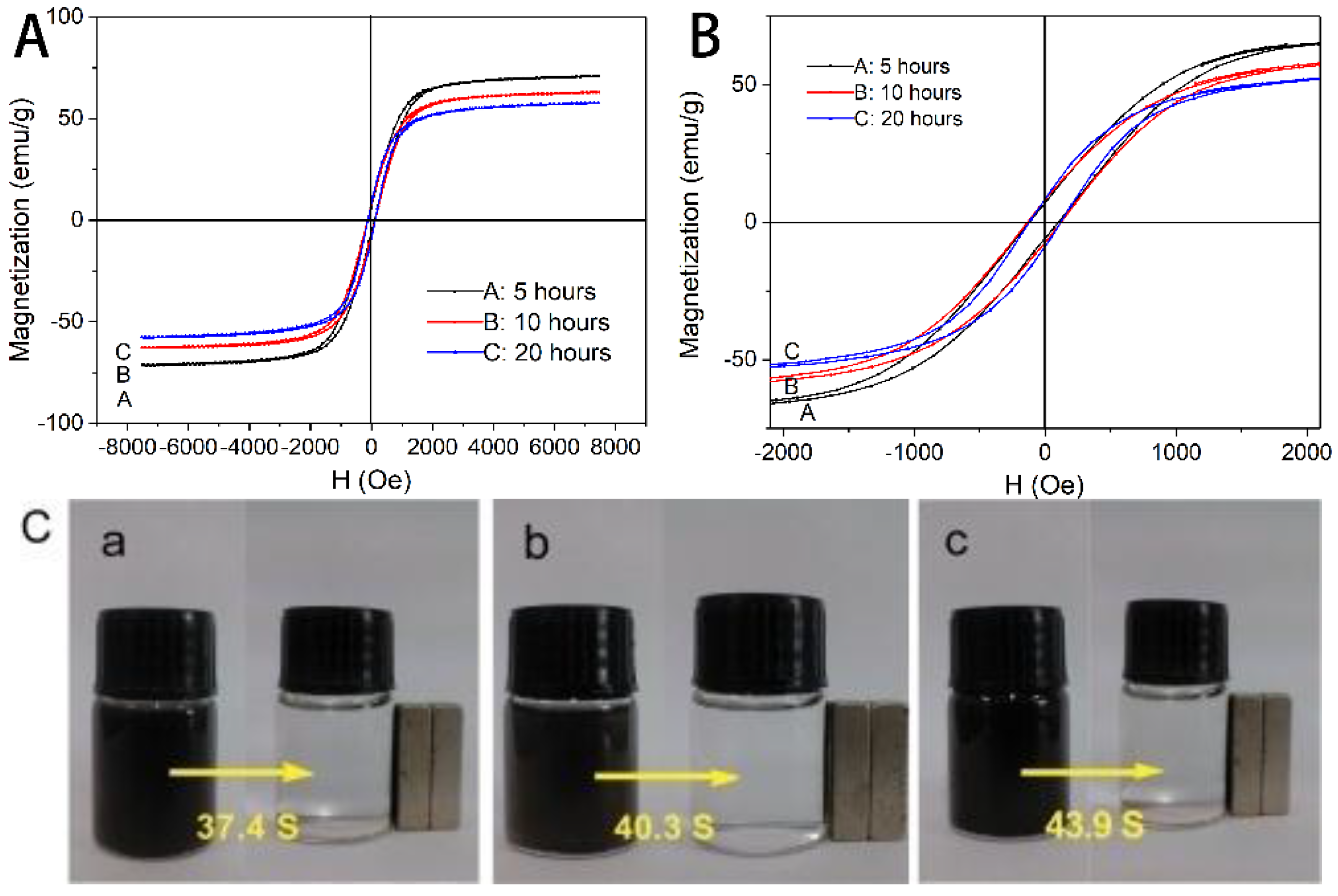
3.3. Morphology, Crystal Structure, and Magnetic Property of Fe3O4 NPs with Different Reaction Time

The reaction time during these hydrothermal routes is also considered. Six experimental groups under different reaction time (5, 6, 8, 10, 12 and 20 h) are carried out, and these sample are named as S10–S15 respectively. Other synthetic conditions in each of these experimental groups are kept the same as those in the typical experiment, and the specific parameters are presented in Table 1. The mixture is transferred into a Teflon-lined stainless steel autoclave (100 mL capacity) for hydrothermal treatment at 200 °C. Firstly, the SEM images of S10–S15 are presented in Figure 9A–F, respectively. As shown in these images, with increasing the reaction time, the particle sizes of the Fe3O4 samples are increased obviously with good dispersity.
In addition, the TEM images and the corresponding size distribution of the as-prepared Fe3O4 particles (S10–S15) are presented in Figure 10. With the prolonging of reaction time, the particle sizes of these Fe3O4 NPs (S10–S15) are increased gradually. As shown in the corresponding particle size distribution map, the average particle sizes of S10–S15 are 184 nm, 214 nm, 217 nm, 222 nm, 213 nm and 241 nm, respectively. The narrow particle size distribution Fe3O4 NPs could also be observed. Moreover, the hollow structure of all these Fe3O4 NPs could be observed clearly. However, with the prolonging of reaction time, as show in the magnified TEM images (Figure 10G–L), the hollow structure is increasingly apparent. These results indicate that the sizes and the hollow structures of as-obtained Fe3O4 NPs are increased with the extension of reaction time, because the time-dependent Ostwald ripening process could form the Fe3O4 NPs with controllable hollow/mesoporous structures.
The XRD patterns of Fe3O4 NPs (S10–S15) with different reaction time are presented in Figure 11. The XRD is conducted to confirm the crystal structure Fe3O4 NPs. As shown in Figure 11, these curves show the characteristic peaks of Fe3O4 NPs, and only these peaks of Fe3O4 NPs are observed, it indicates that the Fe3O4 NPs show good crystallinity with inverse spinel phase. Moreover, the intensities of the peaks in all these curves are almost the same. It indicated that the crystal structure could not influence by the reaction time effectively.
The magnetic property of these Fe3O4 NPs (S10–S15) are also investigated by VSM technique. The specific results are shown in Figure 12. The magnetic saturation Ms values of these as-obtained Fe3O4 NPs in Figure 12A (a: 5 h (S10), b: 10 h (S13), c: 20 h (S15)) are 71.42, 62.5 and 57.78 emu·g−1, respectively. All of the Hc values in Figure 4B are less than 100 Oe (A/m), this result indicate that these NPs are soft magnetic materials. Obviously, the obtained Fe3O4 NPs exhibit the gradually decreased Ms values with the prolonging reaction time. Figure 12C shows the photographs of the suspension of S10, S13 and S15 with an external magnet. These Fe3O4 NPs could also be easy to aggregate and re-disperse in ethyl alcohol solution.

3.4. Formation Mechanism of Fe3O4 NPs

These hollow/mesoporous Fe3O4 nanostructures are synthesized by solvothermal method. In the synthetic process, it is usually proposed that the EG acts both as a high-boiling-point solvent and a reducing agent, and sodium acetate provides as a structure-directive agent. Specifically, EG as a reducing agent is oxidized under heating to generate glycolaldehyde, as shown in formula (1). Then, glycolaldehyde can reduce Fe3+ to Fe2+, and the glyoxal is generated, as shown in formula (2). Moreover, with the increasing of temperature gradually, the Fe[Ac]3 and Fe[Ac]2 are formed by the reaction of Ac and Fe3+ (Fe2+), such as the formulas (3) and (4). As the temperature rising, the Fe(OH)3 and Fe(OH)2 are formed by the hydrolytic and alcoholysis process of Fe[Ac]3 and Fe[Ac]2. These processes are shown in formulas (5)–(8). Finally, the followed Fe3O4 primary NPs are generated via dehydration of these hydrolytic products.
2 H O C H 2 C H 2 O H + O 2 Δ 2 H O C H 2 C H O + 2 H 2 O
H O C H 2 C H O + 2 F e 3 + O H C C H O + 2 H + + 2 F e 2 +
F e 3 + + 3 A c F e [ A c ] 3
F e 2 + + 2 A c F e [ A c ] 2
F e [ A c ] 3 + 3 H 2 O Δ F e ( O H ) 3 + 3 H A c
F e [ A c ] 2 + 2 H 2 O Δ F e ( O H ) 2 + 2 H A c
F e [ A c ] 3 + 3 R O H Δ F e ( O H ) 3 + 3 R A c
F e [ A c ] 2 + 2 R O H Δ F e ( O H ) 2 + 2 R A c
2 F e ( O H ) 3 + F e ( O H ) 2 F e 3 O 4 + 4 H 2 O
Afterwards, in order to reducing the surface energy, these Fe3O4 primary particles could aggregate with magnetic dipole alignment by oriented attachment mechanis [26]. The schematic diagram is presented in Figure 13. However, the formation of the hollow structures without using any templates in this formation process need be further understood. As the reaction goes on, the formation mechanism of these hollow Fe3O4 NPs can further explained by Ostwald ripening mechanism. The inner primary particles could be dissolved and transformed into outer shell. In other words, reducing the overall surface energy provides the driving force for inner particles ripening. As a result, the large-scale synthesis of Fe3O4 nanospheres with hollow structures are formed finally.
Moreover, during the formation mechanism of these Fe3O4 NPs, the Ostwald ripening mechanism play an important role in formation of hollow structure. However, the influence of anhydrous NaAc to the performance of Fe3O4 NPs could also be taken into account. As shown in Table 1, the final Fe3O4 NPs with mesoporous structure or amorphous structure are preferred to form, when the ratio of FeCl3·6H2O and anhydrous NaAc is greater than 1:8. It means that the less anhydrous NaAc is facilitated to form the mesoporous structure. With the increasing of anhydrous NaAc, the Fe3O4 NPs with hollow structure are easily formed. In these reactions, we infer that all these Fe3+ are participated into the reaction, about 1/3 of Fe3+ could be reduced into Fe2+. Theoretically, the three times amount of Ac could coordinate with Fe3+, and two times amount of Ac could coordinate with Fe2+. Thus, the theoretical amount of Ac could be obtained in Table 2. As shown in Table 2, the hollow structures are preferred to form, when the practical amount of Ac is at least two times great than the theoretical amount. The NaAc is added and served not only as an electrostatic stabilization agent to prevent particle agglomeration, but also as an alkaline reagent for providing the alkaline reaction environment, which helps the EG to reduce the Fe3+ into Fe2+.
When the practical amount of Ac is two times less than the theoretical amount, the insufficient Ac is difficult to maintain the stability of this reaction system [27]. Therefore, the as-obtained Fe3O4 primary particles are easy to agglomerate rapidly with each other, under the Ostwald ripening mechanism, the Fe3O4 NPs with mesoporous structure are easily obtained (Figure 13, step C, and E). However, when the practical amount of Ac is two times great than theoretical amount, the aggregated speed of these Fe3O4 primary particles is relatively lower, under the Ostwald ripening process, the Fe3O4 NPs with hollow structure could be formed gradually (Figure 13, Step D and F.). It is considered that the anhydrous NaAc is an associated structure-directing agent, it assists the formation of hollow and mesoporous structure with Ostwald ripening process. Thus, the Fe3O4 NPs with controllable morphology, size and magnetic performance could be obtained by adjusting these synthetic condition [28,29].

4. Conclusions

In summary, the one-pot solvothermal route is applied to prepare Fe3O4 NPs with hollow and mesoporous structure. The different ratio of FeCl3·6H2O and anhydrous NaAc show the great influence on the morphology, size, hollow structure and magnetic property of as-obtained Fe3O4 NPs. Moreover, with the prolonging the reaction time, the particle size become larger, and the hollow structure is getting evident gradually. The final Fe3O4 NPs with obvious hollow structure, relatively smaller diameter (<200 nm) and satisfied magnetic performance are produced. The formation mechanism of these hollow or mesoporous structures is proposal as the NaAc assisted Ostwald ripening mechanism. This controllable method for synthesis of Fe3O4 NPs could provide an excellent example for preparation of other magnetic nanomaterials. Moreover, the hollow Fe3O4 NPs with well-defined structure and magnetic property show a good prospect in drug targeted delivery application.

Acknowledgments

This work was supported by Key Program of Hunan Provincial Department of Science and Technology (2016NK2096), China of Postdoctoral Science Foundation (2016M592456), Hunan Provincial Natural Science Foundation, Doctoral construction program of Hunan University of Technology, Project of Science and Technology Department of Hunan Province, and Zhuzhou Science and Technology Plans (201707-201806).

Author Contributions

Quanguo He, Jun Liu and Wen Li conceived and designed the experiments; Jun Liu and Jing Liang performed the experiments; Jun Liu, Quanguo He and Xiaopeng Liu analyzed the data; Quanguo He, Ziyu Ding and Du Tuo contributed reagents/materials/analysis tools; Quanguo He and Jun Liu wrote the paper.

Conflicts of Interest

The authors declare no conflict of interest.

References

  1. Xiong, Q.Q.; Tu, J.P.; Lu, Y.; Chen, J.; Yu, Y.X.; Qiao, Y.Q.; Wang, X.L.; Gu, C.D. Synthesis of Hierarchical Hollow-Structured Single-Crystalline Magnetite (Fe3O4) Microspheres: The Highly Powerful Storage versus Lithium as an Anode for Lithium Ion Batteries. J. Phys. Chem. C 2012, 116, 6495–6502. [Google Scholar] [CrossRef]
  2. Dorniani, D.; Hussein, M.Z.B.; Kura, A.U.; Fakurazi, S.; Shaari, A.H.; Ahmad, Z. Preparation of Fe3O4 magnetic nanoparticles coated with gallic acid for drug delivery. Int. J. Nanomed. 2012, 7, 5745–5756. [Google Scholar] [CrossRef] [PubMed]
  3. Liu, J.; Huang, C.; He, Q. Pharmaceutical Application of Magnetic Iron Oxide Nanoparticles. Sci. Adv. Mater. 2015, 7, 672–685. [Google Scholar] [CrossRef]
  4. He, Q.; Liu, J.; Huang, C.; Wu, W. Synthesis and Characterization of a Silver Incorporated Magnetic Nanocomposite with Enhanced Antibacterial Activity. Sci. Adv. Mater. 2014, 6, 366–376. [Google Scholar] [CrossRef]
  5. He, Q.; Liu, J.; Huang, C.; Wu, Z. A Nanoscale System for Remarkably Enhanced Drug Delivery Based on Hollow Magnetic Particles Encapsulated Within Temperature-Responsive Poly(methylmethacrylate). Sci. Adv. Mater. 2014, 6, 387–398. [Google Scholar] [CrossRef]
  6. Yu, J.; Yu, X.; Huang, B.; Zhang, X.; Dai, Y. Hydrothermal Synthesis and Visible-light Photocatalytic Activity of Novel Cage-like Ferric Oxide Hollow Spheres. Cryst. Growth Des. 2009, 9, 1474–1480. [Google Scholar] [CrossRef]
  7. An, K.; Kwon, S.G.; Park, M.; Na, H.B.; Baik, S.-I.; Yu, J.H.; Kim, D.; Son, J.S.; Kim, Y.W.; Song, I.C.; Moon, W.K.; Park, H.M.; Hyeon, T. Synthesis of Uniform Hollow Oxide Nanoparticles through Nanoscale Acid Etching. Nano Lett. 2008, 8, 4252–4258. [Google Scholar] [CrossRef] [PubMed]
  8. Cheng, K.; Peng, S.; Xu, C.; Sun, S. Porous Hollow Fe3O4 Nanoparticles for Targeted Delivery and Controlled Release of Cisplatin. J. Am. Chem. Soc. 2009, 131, 10637–10644. [Google Scholar] [CrossRef] [PubMed]
  9. Wei, J.; Du, A.; Jin, F.; Wang, Z.; Liu, X. The preparation and high-frequency electromagnetic properties of ferrimagnetic bisphthalonitrile–Fe3O4 core–shell hollow microspheres. J. Magn. Magn. Mater. 2013, 340, 70–75. [Google Scholar] [CrossRef]
  10. Yang, S.; Liu, H.; Zhang, Z. Fabrication of Novel Multihollow Superparamagnetic Magnetite/Polystyrene Nanocomposite Microspheres via Water-in-Oil-in-Water Double Emulsions. Langmuir 2008, 24, 10395–10401. [Google Scholar] [CrossRef] [PubMed]
  11. Ostwald, W. Studien über die Bildung und Umwandlung fester Körper. Zeitschrift für Physikalische Chemie 1897, 22U, 289–330. [Google Scholar]
  12. Peng, S.; Sun, S. Synthesis and Characterization of Monodisperse Hollow Fe3O4 Nanoparticles. Angew. Chem. Int. Edit. 2007, 46, 4155–4158. [Google Scholar] [CrossRef] [PubMed]
  13. Wang, Q.; Geng, B.; Wang, S.; Ye, Y.; Tao, B. Modified Kirkendall effect for fabrication of magnetic nanotubes. Chem. Commun. 2010, 46, 1899–1901. [Google Scholar] [CrossRef] [PubMed]
  14. Ong, Q.K.; Lin, X.-M.; Wei, A. The Role of Frozen Spins in the Exchange Anisotropy of Core–Shell Fe@Fe3O4 Nanoparticles. J. Phys. Chem. C 2011, 115, 2665–2672. [Google Scholar] [CrossRef] [PubMed]
  15. Chae, H.S.; Piao, S.H.; Choi, H.J. Fabrication of spherical Fe3O4 particles with a solvothermal method and their magnetorheological characteristics. J. Ind. Eng. Chem. 2015, 29, 129–133. [Google Scholar] [CrossRef]
  16. Ren, Y.; Zhang, H.; Chen, B.; Cheng, J.; Cai, X.; Liu, R.; Xia, G.; Wu, W.; Wang, S.; Ding, J.; Gao, C.; Wang, J.; Bao, W.; Wang, L.; Tian, L.; Song, H.; Wang, X. Multifunctional magnetic Fe3O4 nanoparticles combined with chemotherapy and hyperthermia to overcome multidrug resistance. Int. J. Nanomed. 2012, 7, 2261–2269. [Google Scholar]
  17. Zhang, W.; Qiao, L.; Wang, X.; Senthilkumar, R.; Wang, F.; Chen, B. Inducing cell cycle arrest and apoptosis by dimercaptosuccinic acid modified Fe3O4 magnetic nanoparticles combined with nontoxic concentration of bortezomib and gambogic acid in RPMI-8226 cells. Int. J. Nanomed. 2015, 10, 3275–3289. [Google Scholar]
  18. He, Q.; Liu, J.; Hu, R. Facile Magnetosensitive Catalyst Fabrication of Palladium/Platinum Coated Maghemite Nanocomposites and Characterization. Nanosci. Nanotechnol. Lett. 2013, 5, 995–1001. [Google Scholar] [CrossRef]
  19. Wu, W.; He, Q.; Chen, H.; Tang, J.; Nie, L. Sonochemical synthesis, structure and magnetic properties of air-stable Fe3O4/Au nanoparticles. Nanotechnology 2007, 18, 145609. [Google Scholar] [CrossRef]
  20. Akbarzadeh, A.; Mikaeili, H.; Zarghami, N.; Mohammad, R.; Barkhordari, A.; Davaran, S. Preparation and in vitro evaluation of doxorubicin-loaded Fe3O4 magnetic nanoparticles modified with biocompatible copolymers. Int. J. Nanomed. 2012, 7, 511. [Google Scholar]
  21. Liu, J.; Yang, S.; Wu, W.; Tian, Q.; Cui, S.; Dai, Z.; Ren, F.; Xiao, X.; Jiang, C. 3D flowerlike α-Fe2O3@TiO2 core–shell nanostructures: general synthesis and enhanced photocatalytic performance. ACS Sustainable Chem. Eng. 2015, 3, 2975–2984. [Google Scholar] [CrossRef]
  22. An, J.S.; Han, W.J.; Choi, H.J. Synthesis of hollow magnetite nanoparticles via self-assembly and their magnetorheological properties. Colloid. Surfaces A 2017, 535, 16–23. [Google Scholar] [CrossRef]
  23. Lin, X.; Ji, G.; Liu, Y.; Huang, Q.; Yang, Z.; Du, Y. Formation mechanism and magnetic properties of hollow Fe3O4 nanospheres synthesized without any surfactant. CrystEngComm 2012, 14, 8658–8663. [Google Scholar] [CrossRef]
  24. He, Q.; Wu, Z.; Huang, C. Dual gas-bubble-assisted solvothermal synthesis of magnetite with tunable size and structure. J. Nanosci. Nanotechnol. 2011, 11, 8568–8575. [Google Scholar] [CrossRef] [PubMed]
  25. He, Q.; Liu, J.; Liu, X.; Li, G.; Deng, P.; Liang, J. Preparation of Cu2O-Reduced Graphene Nanocomposite Modified Electrodes towards Ultrasensitive Dopamine Detection. Sensors 2018, 18, 199. [Google Scholar] [CrossRef] [PubMed]
  26. Tian, X.; Li, J.; Chen, K.; Han, J.; Pan, S.; Wang, Y.; Fan, X.; Li, F.; Zhou, Z. Nearly monodisperse ferroelectric BaTiO3 hollow nanoparticles: size-related solid evacuation in ostwald-ripening-induced hollowing process. Cryst. Growth Des. 2010, 10, 3990–3995. [Google Scholar] [CrossRef]
  27. Deng, H.; Li, X.; Peng, Q.; Wang, X.; Chen, J.; Li, Y. Monodisperse magnetic single crystal ferrite microspheres. Angew. Chem. 2005, 117, 2842–2845. [Google Scholar] [CrossRef]
  28. Liu, S.; Xing, R.; Lu, F.; Rana, R.K.; Zhu, J.-J. One-pot template-free fabrication of hollow magnetite nanospheres and their application as potential drug carriers. J. Phys. Chem. C 2009, 113, 21042–21047. [Google Scholar] [CrossRef]
  29. He, Q.; Liu, J.; Liang, J.; Liu, X.; Tuo, D.; Li, W. Chemically Surface Tunable Solubility Parameter for Controllable Drug Delivery—An Example and Perspective from Hollow PAA-Coated Magnetite Nanoparticles with R6G Model Drug. Materials 2018, 11, 247. [Google Scholar] [CrossRef] [PubMed]
Figure 1. SEM images of Fe3O4 with different molar quantity of FeCl3·6H2O, (A) 0.4 mmol; (B) 5 mmol; (C) 10 mmol; (D) 20 mmol.
Applsci 08 00292 g001
Figure 2. TEM images and size distribution patterns of Fe3O4 with different molar ratio of FeCl3·6H2O, (A) 0.4 mmol; (B) 5 mmol; (C) 10 mmol; (D) 20 mmol, the insets are the corresponding size distribution patterns. (EH) is the corresponding magnification images.
Applsci 08 00292 g002
Figure 3. XRD patterns of Fe3O4 obtained with different molar ratio of FeCl3·6H2O, A: 0.4 mmol, B: 5 mmol, C: 10 mmol, D: 20 mmol.
Applsci 08 00292 g003
Figure 4. The hysteresis loops at T = 300 K of Fe3O4 (A) and corresponding partly amplification images (B) with different molar ratio of FeCl3·6H2O (a) 0.4 mmol, (b) 5 mmol, (c) 20 mmol; (C) photograph of magnetic isolation.
Applsci 08 00292 g004aApplsci 08 00292 g004b
Figure 5. SEM images of Fe3O4 with different molar ratio of NaAc, (A) 5 mmol; (B) 10 mmol; (C) 20 mmol; (D) 40 mmol; (E) 60 mmol.
Applsci 08 00292 g005
Figure 6. TEM images and size analysis patterns of Fe3O4 with different molar ratio of NaAc, (A) 5 mmol; (B) 10 mmol; (C) 20 mmol; (D) 40 mmol; (E) 60 mmol, the insets are the corresponding size distribution patterns; (FJ) is the corresponding magnification images, respectively.
Applsci 08 00292 g006
Figure 7. XRD patterns of Fe3O4 obtained with different molar ratio of FeCl3·6H2O, A: 0.4 mmol, B: 5 mmol, C: 10 mmol, D: 20 mmol.
Applsci 08 00292 g007
Figure 8. The hysteresis loops at T = 300 K of Fe3O4 (A) and corresponding partly amplification images (B) with different molar ratio of NaAc (a) 10 mmol, (b) 40 mmol, (c) 60 mmol; (C) photograph showing magnetic isolation.
Applsci 08 00292 g008
Figure 9. SEM images of Fe3O4 with different reaction time, (A) 5 h, (B) 6 h, (C) 8 h, (D) 10 h, (E) 12 h, (F) 20 h.
Applsci 08 00292 g009
Figure 10. TEM images and size analysis patterns of Fe3O4 with different reaction time, (A) 5, (B) 6, (C) 8, (D) 10, (E) 12, (F) 20 (h); the insets are the corresponding size distribution patterns. (GL) is the corresponding magnification images respectively.
Applsci 08 00292 g010
Figure 11. XRD patterns of Fe3O4 obtained with different reaction time, 5 h; B: 6 h; C: 8 h; D: 10 h; E: 12 h; F: 20 h.
Applsci 08 00292 g011
Figure 12. The hysteresis loops at T = 300 K of Fe3O4 (A) and corresponding partly amplification images (B) with different reaction time (a) 5 h, (b) 10 h, (c) 20 h; (C) photograph showing magnetic isolation.
Applsci 08 00292 g012
Figure 13. Schematic illustration of the process of magnetite mesoporous hollow spheres formation.
Applsci 08 00292 g013
Table 1. The major morphology of samples obtained in specific experimental condition, A: FeCl3·6H2O, B: NaAc.
ParameterSample No.A mmolB mmolA:BReaction Time (hours)Reaction Tempereture (°C)Average Dimension (nm)Major Morphology
n(A)S10.4401:10010200101Little hollow structure with small solid particles
S25401:810200222Hollow structure
S310401:410200116Mesoporous structure
S420401:21020091Flowerlike nanospheres with Mesoporous structure
n(B)S5551:11020085Microcrystalline grain, bulk structure
S65101:210200122Hollow structure with hole in the wall
S75201:410200103Flowerlike nanospheres with Mesoporous structure
S85401:810200222Hollow structure
S95601:1210200256Hollow structure
Reaction TimeS105401:85200184larger particles without obvious hollow structure
S115401:86200212larger particles without obvious hollow structure
S125401:88200217Hollow structure
S135401:810200222Hollow structure
S145401:812200213Hollow structure
S155401:820200241Hollow structure
Table 2. The comparison of the theoretical amount and the practical amount of samples in specific experimental condition.
Fe3+ Added Amount (mmol)Ac Added Amount (mmol)Fe2+ Theoretical Amount (mmol)Fe3+ Theoretical Amount (mmol)Ac Theoretical Amount (mmol)
0.4400.1330.2671.07
5401.6673.33313.33
10403.3336.66726.67
20406.66713.33353.33
551.6673.33313.33
5101.6673.33313.33
5201.6673.33313.33
5401.6673.33313.33
5601.6673.33313.33

