Article

Manufacturing of Non-Stick Molds from Pre-Painted Aluminum Sheets via Single Point Incremental Forming

by
Oscar Rodriguez-Alabanda
,
Miguel A. Narvaez
,
Guillermo Guerrero-Vaca
and
Pablo E. Romero
*
Department of Mechanical Engineering, University of Cordoba, Medina Azahara Avenue 5, 14071 Cordoba, Spain
*
Author to whom correspondence should be addressed.
Submission received: 29 May 2018 / Revised: 17 June 2018 / Accepted: 18 June 2018 / Published: 20 June 2018
(This article belongs to the Special Issue Mechanical Behaviour of Aluminium Alloys)

Abstract

:

Featured Application

In this work we propose a method for deforming a pre-coated metal sheet via SPIF. The influence of the pitch and feed-rate on the dimensional precision has been studied. This work is of interest for companies dedicated to the manufacture of molds for the agri-food sector, which can directly manufacture prototypes or short series by this system.

Abstract

The process of single point incremental formation (SPIF) awakens interest in the industry of mold manufacturing for the food industry. By means of SPIF, it is possible to generate short series of molds or mold prototypes at low cost. However, these industries require such molds to be functional (non-sticky) and to have an adequate geometry accuracy. This study presents a technique that enables direct manufacturing of molds from pre-coated sheets with non-stick resins. It has also studied the influence of two technological variables in the process (feed-rate and pitch) for different geometrical parameters of the mold. Low values of these variables result in a lower overall error in the profile obtained. However, in order to obtain greater detail in particular parameters (angles, depth), it is necessary to use higher values of feed-rate and pitch.

1. Introduction

Single point incremental formation (SPIF), patented by Leszak in 1967 [1] and later developed by Prof. Matsubara [2] and Kitazawa et al. [3], consists of the progressive deformation of a metal sheet by means of a steel punch at the top of a machining center or robot. The forming is done in such a way that neither presses nor dies are necessary [4].
The SPIF technique enables the manufacturing of prototypes from sheet materials. By means of SPIF, forming can be done to all types of metals and alloys: aluminum, steel, stainless steel, tin, copper, titanium, among others [5,6]. Polymers can also be worked with [7]: polyamide (PA), polyethylene (PE), polyvinyl chloride (PVC), polystyrene (PS), polypropylene (PP), polycarbonate (PC), polyethylene terephthalate (PET). The advantages and disadvantages of the process are summarized in Table 1.
As well as prototypes, with SPIF, it is also possible to obtain short manufacturing series at low cost. Petek et al. [8] determined that SPIF technology is more profitable than deep drawing up to a batch size of 600 pieces. Ingarao et al. [9] affirm that SPIF is a more efficient process than deep forming processes which produce cuttings and scrap metal.
The process has evolved in recent years [11], and its use has increased in different sectors, such as automotive [12,13,14,15,16], medicine [17,18,19], energy [20], architecture [21], and art [22]. One of the least explored uses of this process is in the manufacturing of molds. Fiorotto et al. [23] have proposed the use of molds made by means of SPIF directed at compound material sheeting. Appermont et al. [24] and Afonso et al. [25] have considered its use in thermoforming operations. Recently, it has been tested in rotomolding processes, and in other polymer processing techniques [26].
In most cases, for the demolding process, it is desirable for the mold to have a non-stick coating. These coatings may be of several types, although the most common are those made with resins that are rich in fluoropolymers [27]. Such resins may be applied to the metal sheets before forming, so that the manufactured piece is the final one. However, until now the friction between the tool and the sheet complicated the forming process with pre-coated SPIF sheeting [28].
In order to avoid direct contact between the tool and the coating, in this study, the dummy technique [29,30] has been used: a dummy sheet is placed over the sheet to be formed, and the punch simultaneously forms both sheets, without any direct contact with the lower pre-coated sheet. This novel method enables the application of the SPIF process to sheets pre-coated in resins rich in fluoropolymers, and thus, among other applications, directly manufacture prototypes or short series of non-stick molds.
The aluminum–magnesium alloy EN AW 5754 H32 is commonly used to manufacture molds in the food industry, as it comes into contact with food and has good formability [31]. The incremental forming of this material has been studied previously by Verbert [32], Behera [33], and Gupta & Jeswiet [34].
For the industrial use of SPIF, it is imperative to reduce springback and achieve good geometrical accuracy [10]. There are previous studies that have analyzed this matter with aluminum alloys. Ambrogio et al. [35,36] focused on the improvement of the dimensional accuracy of truncated cone pieces from sheets of EN AW 1050-O. Guzman et al. [37] advanced in the accuracy reached using SPIF in two-slope cones manufactured in EN AW 3003. However, no previous studies have been found in the literature concerning the geometrical accuracy reached using SPIF with sheets of EN AW 5754 H32, nor authors who have approached this subject using the dummy method.
This work has two main aims. The first is to present and describe the use of the dummy method in incremental forming for the direct manufacturing of prototypes or short series of molds. The second aim is to study the influence of two technological parameters, pitch and feed-rate, in the accuracy reached in the manufacturing of truncated pyramidal geometry. The piece was manufactured using SPIF in EN AW 5754 H32 aluminum–magnesium sheets, pre-coated with resins rich in polytetrafluoroethylene (PTFE). The geometrical variables measured were initial and final angle, minimum thickness, depth, height, normalized springback, and area variation between theoretical and experimental profile.
The structure of the study is the following: Section 2 describes the equipment and material used in both the forming process and the measuring; Section 3 shows the results, which are discussed in Section 4; finally, the conclusions are presented in Section 5.

2. Materials and Methods

The dummy method in SPIF consists of the simultaneous deforming of two overlapping sheets [38]. This method has been used to improve the surface finish [29] and to deform previously welded sheets by means of friction stir welding [30]. In this case, the dummy method was used to manufacture non-stick molds from sheets pre-coated with PTFE resin (Figure 1).
The molds were made with aluminum–magnesium EN AW 5754-H32 sheets, the dimensions being 210 × 210 mm and 1.2 mm thick. On one side, a circular pattern was printed to control the deforming undergone at each point [39]. The other side was covered with a resin-rich PTFE. To protect this re-covering during the incremental deforming, a PVC dummy sheet of 210 × 210 mm and 3.0 mm thick was used.
The design chosen for the molds was a truncated pyramidal geometrical shape, as it is of industrial interest and facilitates the geometrical characteristics. Several tests were carried out in order to determine the maximum depth and angle that the sheets were able to reach. The final dimensions are shown in Figure 2.
The pieces were drawn using SolidWorks parametric software. Once drawn, the models were exported to the MasterCAM program, where the strategy was defined, and the technological parameters of the process were determined. This being done, the MasterCAM automatically generated the NC programs. The tool path strategy used was contour-parallel.
Nine tests were carried out, with different pitch and feed-rate values. For the pitch, the values 0.3, 0.6 and 1.0 mm were used; for the feed-rate, the values were 1800, 2000 and 2200 mm/min. The spindle speed in all cases was set at 750 RPM.
The geometrical parameters and technologies were selected according to database collected from the literature (Table 2) and after carrying out several sensitivity tests (Table 3). Breakage of any of the materials was avoided (PVC, PTFE, EN-AW 5754), since the aim was to attain healthy molds that could be studied geometrically.
It is important to bear in mind that during the process, there is a simultaneous deformation of two sheets with very different mechanical properties and behaviors. The dummy sheet (PVC) is that which is in contact with the punch, so that, although the intention is to deform the aluminum, it is necessary to work with values that are compatible with the PVC (Table 2).
The tests were carried out at a model QP2026-L Chevalier machining center, equipped with a Fanuc numerical control. The tool used for the forming was a 14.68 mm diameter punch, made up of two pieces: an EN AW 2024 aluminum body and a stainless steel spherical tip. SAE 30 mineral oil was used for lubrication, following the recommendations of Azevedo et al. [46]. Experiment set-up is shown in Figure 3.
Once the pieces were manufactured, different geometrical parameters were measured (Figure 4): minimum thickness, depth, height, initial angle, elastic recovery, and area of deviation between theoretical and real profile.
Depth was measured using a depth gauge and gauge blocks. Four measurements were taken in each mold. Height was measured on marble, using a height measure and four different measurements were also taken in each mold.
Angle #1 was measured with a goniometer. From this angle measured (actual) and the theoretical angle (CAD), the normalized springback was calculated, by means of the expression Equation (1), proposed by Martins et al. [7].
  S n = ( Ψ C A D Ψ a c t u a l ) Ψ C A D × 100
To measure the thickness, the molds were cut in half using a belt saw. Once this was done, different measurements were taken along the profile (one measurement every 10 mm) using a 0.01 precision micrometer. Fifty-six measurements were taken for each piece.
Once cut, the pieces were photographed. The images were imported from the AutoCAD program. Once scaled, the sections were drawn over them, which were used to measure angle #2. Besides this, the sections were compared with the theoretical profile of the mold. The area enclosed between them gives the overall error existing between both profiles.

3. Results

Figure 5 shows the exterior angle or angle #1 measured in each of the molds manufactured via SPIF with a dummy sheet. The theoretical angle sought after was 45°. Figure 6 shows the interior angle or angle #2. In this case, the theoretical angle sought after was 135°. The minimum thickness measured in the sections of the different pieces is shown in Figure 7. As can be observed, it shows no great variations for the different cases studied.
Figure 8 shows the average height and depth values measured in each mold. As can be appreciated, both parameters are closer to the expected theoretical measurements for greater values of pitch and feed-rate.
The normalized springback measured in the different tests can be seen in Figure 9. Here, the pitch is not seen to be an influencing factor. However, it appears that lower values of springback are associated with high values of feed-rate speed.
The area between the theoretical profile and the real one for each mold is shown in Figure 10. This area gives an idea of the overall error existing between the sought-after piece and the one obtained.
Figure 11 shows the forming limit diagram (FLD) corresponding to the manufactured molds with a feed-rate equal to 2000 mm/min. As can be observed, the greater the pitch, the greater the main deformations.

4. Discussion

The dummy method was inserted into the SPIF by Skjoedt et al. [38]. The initial aim was to improve the surface finish of the manufactured metallic pieces by incremental deforming [29]. Later, the dummy method was used to deform welded sheets by means of friction stir welding [30]. In the present study, the dummy method has been used to conform, directly via SPIF, pre-coated molds rich in a PTFE resin.
As well as presenting this novel method for directly manufacturing non-stick molds by incremental deforming, the present work has also studied the influence of both technological parameters (pitch and feed-rate) on the dimensional precision reached during the incremental forming of molds from pre-coated sheets using the dummy technique.
After analyzing the results, we can affirm the following:
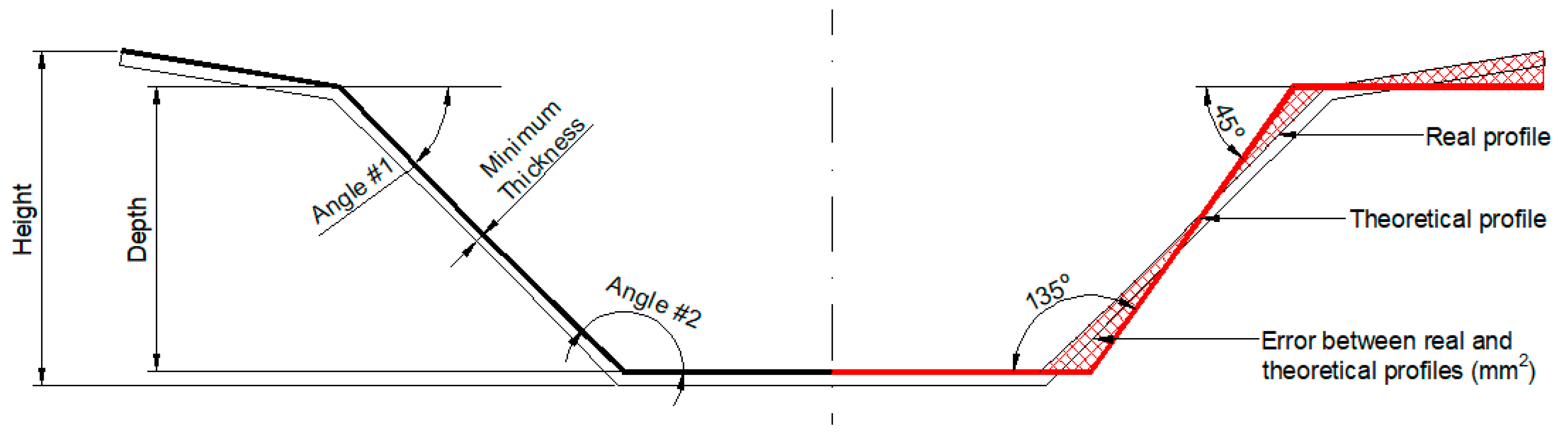
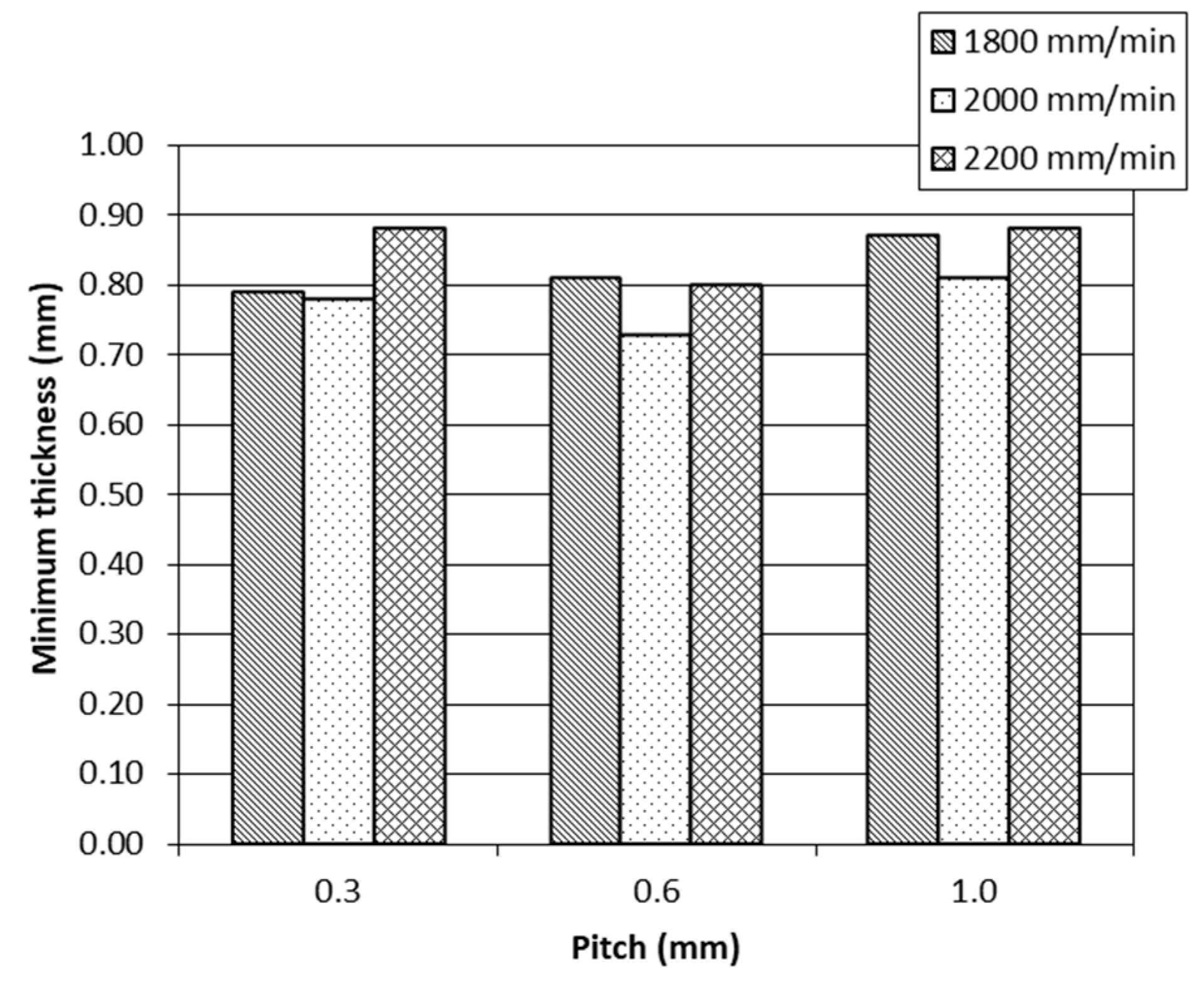
  • The minimum thickness appears to show no relation to any of the technological parameters studied (Figure 7). This result is coherent with the law of sine [47]. According to this law, the theoretical thickness can be calculated as a product of the initial thickness (1.20 mm) and the sine of the angle (45°). The theoretical value calculated (0.84 mm) coincides with the value measured experimentally.
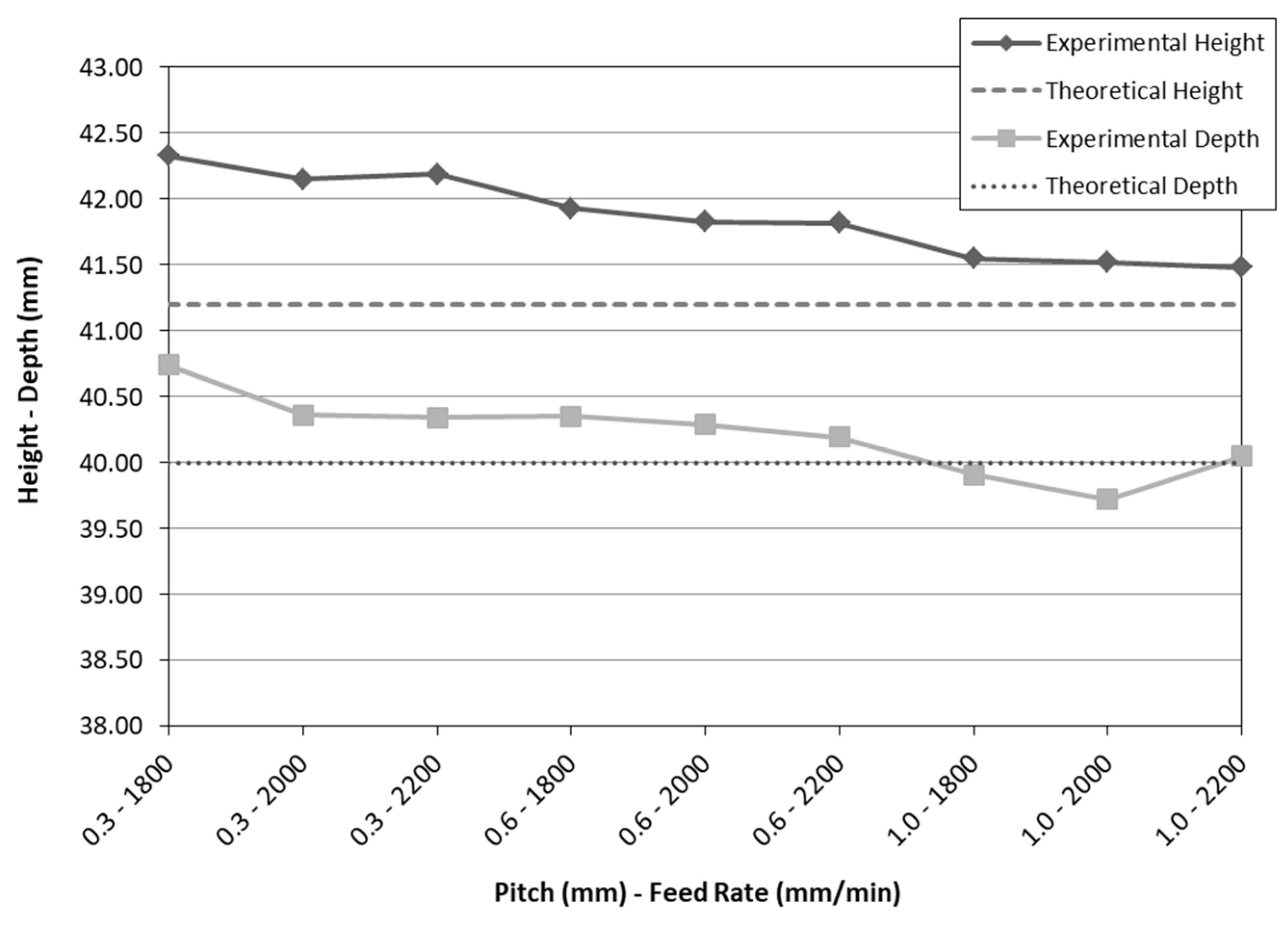
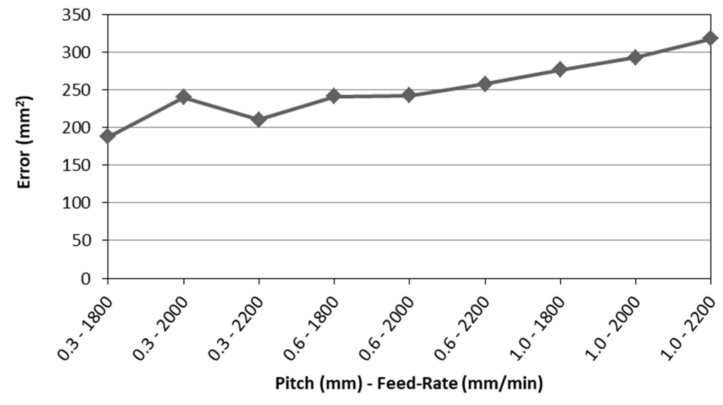
  • The differences between the theoretical profile and the real profile of the mold are minor, in general terms, when using low values of pitch and feed-rate (Figure 10). These results coincide with those obtained by Hussain, Lin & Hayat [48] (greater pitches provoke greater deviations), Maqbool & Bambach [49] (lower pitches provoke lower geometrical accuracy) and Radu & Cristea [50] (high values of the feed-rate lead to a low-dimensional accuracy).
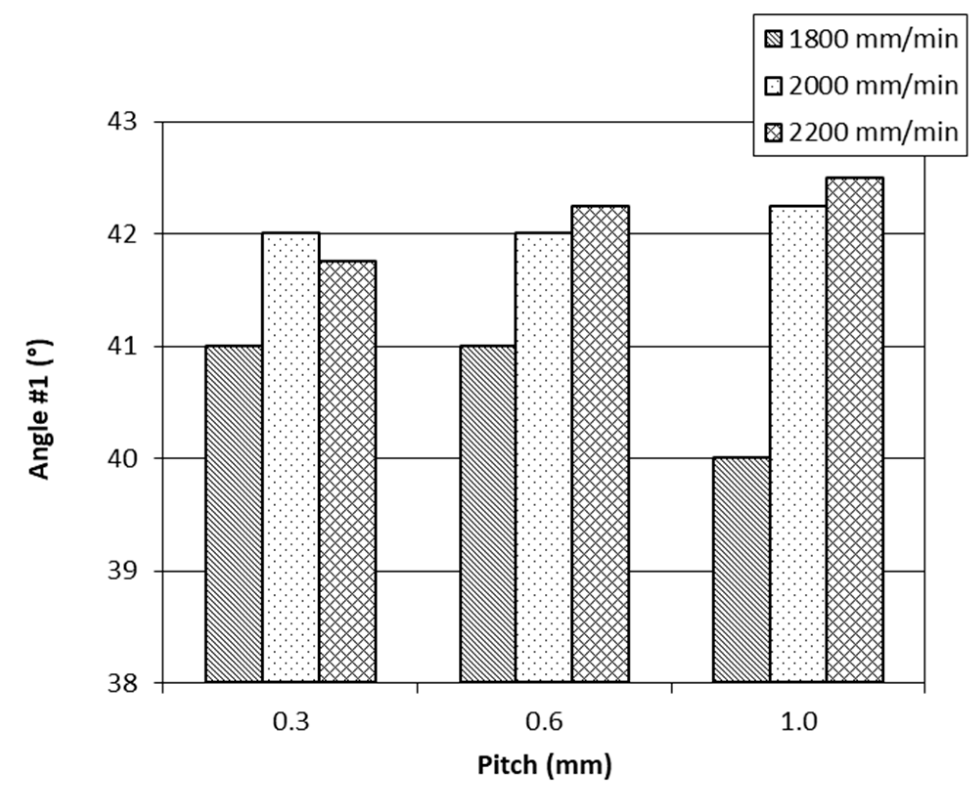
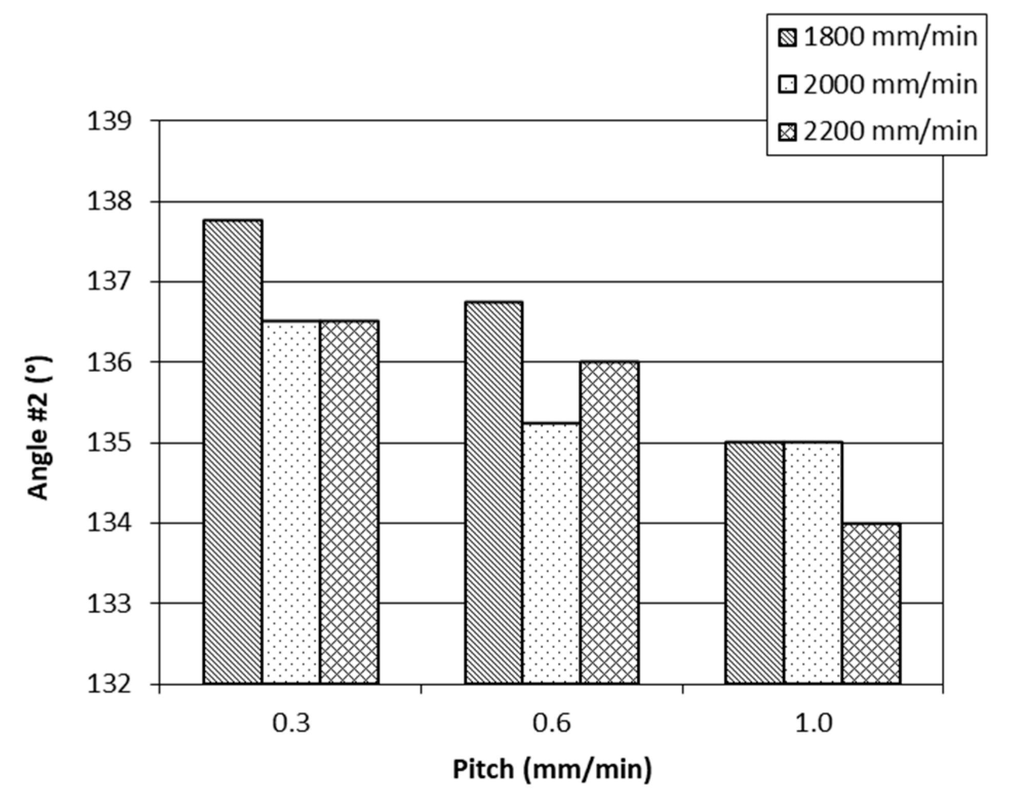
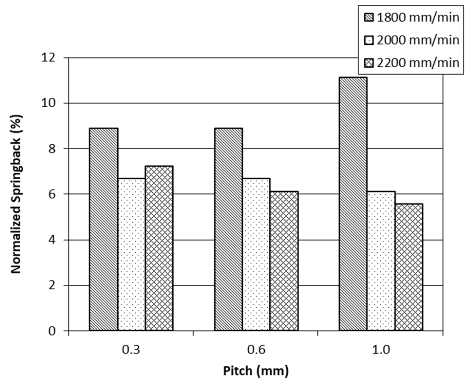
  • However, low values of pitch and feed-rate result in certain geometrical features (depth, height, angle #1, normalized springback, angle #2) moving away from the sought-after theoretical values:
    • The depth and height approach the theoretical ones with high pitch and feed-rate values (Figure 8).
    • Angle #1 approaches the sought-after value (45°) when high feed-rate values are programmed (Figure 5). Logically, the normalized springback shows the same behavior (Figure 9).
    • Angle #2 (135°) approaches the sought-after value when greater pitch values are used (Figure 6).
  • An increase in pitch increases the deformability (Figure 11). This result coincides with that presented by Liu et al. [51].
As can be appreciated, the test carried out with a greater pitch and feed-rate attains better results for the particular variables (height, depth, initial angle, maximum angle, minimum thickness). At the other end, the test carried out with a lower pitch and feed-rate manages to minimize the deviation area between the profile obtained and the expected theoretical one.
To sum up, it can be affirmed that the results obtained relative to geometrical accuracy in the dummy method are similar to those obtained in the incremental deforming processes of a single sheet. To solve this problem, Bambach, Araghi & Hirt [13] proposed a multistage strategy to improve geometrical accuracy. Following this idea, the authors are going to try a multi-stage strategy: firstly, high values of pitch and feed-rate will be used to get a good reproduction of the geometry details; secondly, lower values of pitch and feed-rate will be used to provide a lesser deviation in the real compared to the theoretical profile.

5. Conclusions

The present study has analyzed the geometrical accuracy obtained in the SPIF process of sheets pre-coated with resins rich in PTFE, using the dummy method. To do so, truncated pyramidal shapes were formed in EN-AW 5754 sheets of aluminum–magnesium with a PVC dummy sheet, using different pitch and feed-rate values.
The experiments carried out show that there is no apparent relation between some of the geometrical parameters studied (minimum thickness) and the technological parameters cited. However, it has been proven that there is a relation between the remaining parameters: the normalized springback value decreases with greater feed-rate values; height and depth get closer to the sought-after values when greater values of pitch and feed-rate are programmed; the area between the real and the theoretical profile (a measurement of error) also increase when using greater pitch and feed-rate values.
These results are of great interest to the local industrial sector involved in the manufacture of molds and trays for food products which, in the SPIF with dummy process, find a method for manufacturing prototypes from pre-coated sheets.
Future studies will address the geometrical accuracy obtained in incremental deforming processes using multi-stage strategy. In the initial stages, high values of pitch and feed-rate will be used in order to guarantee a good reproduction of the geometry details. In the final stages, lower values of pitch and feed-rate will be used that will provide a lesser deviation in the real compared to the theoretical profile. Besides this, the exact angles and maximum depths that can be reached by sheets of this material with different thicknesses will be studied, using different values of spindle speed and different tool diameters.

Author Contributions

O.R.-A. and P.E.R. conceived and designed the experiments; O.R.-A. and M.A.N. performed the experiments; M.A.N., G.G.-V. and P.E.R. analyzed the data; O.R.-A. and P.E.R. wrote the paper; G.G.-V. revised the paper.

Funding

This research received no external funding.

Conflicts of Interest

The authors declare no conflict of interest.

References

  1. Leszak, E. Apparatus and Processs for Incremental Dieless Forming. U.S. Patent 3342051, 19 September 1967. [Google Scholar]
  2. Matsubara, S. Incremental backward bulge forming of a sheet metal with a hemispherical head tool. Jpn. Soc. Technol. Plast. 1994, 35, 1311–1316. [Google Scholar]
  3. Kitazawa, K.; Wakabayashi, A.; Murata, K.; Yaejima, K. Metal-flow phenomena in computerized numerically controlled incremental stretch-expanding of aluminum sheets. J. Jpn. Inst. Light Met. 1996, 46, 65–70. [Google Scholar] [CrossRef]
  4. Jeswiet, J.; Micari, F.; Hirt, G.; Bramley, A.; Duflou, J.; Allwood, J. Asymmetric Single Point Incremental Forming of Sheet Metal. CIRP Ann. Manuf. Technol. 2005, 54, 88–114. [Google Scholar] [CrossRef]
  5. Afonso, D.; de Sousa, R.; Torcato, R. Integration of design rules and process modelling within SPIF technology—A review on the industrial dissemination of single point incremental forming. Int. J. Adv. Manuf. Technol. 2018, 94, 4387–4399. [Google Scholar] [CrossRef]
  6. McAnulty, T.; Jeswiet, J.; Doolan, M. Formability in single point incremental forming: A comparative analysis of the state of the art. CIRP J. Manuf. Sci. Technol. 2017, 16, 43–54. [Google Scholar] [CrossRef]
  7. Martins, P.A.F.; Kwiatkowski, L.; Franzen, V.; Tekkaya, A.E.; Kleiner, M. Single point incremental forming of polymers. CIRP Ann. Manuf. Technol. 2009, 58, 229–232. [Google Scholar] [CrossRef] [Green Version]
  8. Petek, A.; Gantar, G.; Pepelnjak, T.; Kuzman, K. Economical and Ecological Aspects of Single Point Incremental Forming Versus Deep Drawing Technology. Key Eng. Mater. 2007, 344, 931–938. [Google Scholar] [CrossRef]
  9. Ingarao, G.; Ambrogio, G.; Gagliardi, F.; Di Lorenzo, R. A sustainability point of view on sheet metal forming operations: Material wasting and energy consumption in incremental forming and stamping processes. J. Clean. Prod. 2012, 29–30, 255–268. [Google Scholar] [CrossRef]
  10. Echrif, S.B.M.; Hrairi, M. Research and Progress in Incremental Sheet Forming Processes. Mater. Manuf. Process. 2011, 26, 1404–1414. [Google Scholar] [CrossRef]
  11. Behera, A.K.; de Sousa, R.A.; Ingarao, G.; Oleksik, V. Single point incremental forming: An assessment of the progress and technology trends from 2005 to 2015. J. Manuf. Process. 2017, 27, 37–62. [Google Scholar] [CrossRef] [Green Version]
  12. Zha, G.; Xu, J.; Shi, X.; Zhou, X.; Lu, C. Forming process of automotive body panel based on incremental forming technology. Metall. Min. Ind. 2015, 12, 350–357. [Google Scholar]
  13. Bambach, M.; Taleb Araghi, B.; Hirt, G. Strategies to improve the geometric accuracy in asymmetric single point incremental forming. Prod. Eng. 2009, 3, 145–156. [Google Scholar] [CrossRef]
  14. Governale, A.; Lo Franco, A.; Panzeca, A.; Fratini, L.; Micari, F. Incremental Forming Process for the Accomplishment of Automotive Details. Key Eng. Mater. 2007, 344, 559–566. [Google Scholar] [CrossRef]
  15. Romero, P.E.; Aguilar-Contreras, F.J.; Dorado, R.; Lopez-Garcia, R. Rapid prototyping for automotive industry via incremental sheet forming. DYNA 2013, 88, 581–590. [Google Scholar]
  16. Amino, M.; Mizoguchi, M.; Terauchi, Y.; Maki, T. Current status of “Dieless” Amino’s incremental forming. Procedia Eng. 2014, 81, 54–62. [Google Scholar] [CrossRef]
  17. Ambrogio, G.; De Napoli, L.; Filice, L.; Gagliardi, F.; Muzzupappa, M. Application of Incremental Forming process for high customised medical product manufacturing. J. Mater. Process. Technol. 2005, 162–163, 156–162. [Google Scholar] [CrossRef]
  18. Castelan, J.; Schaeffer, L.; Daleffe, A.; Fritzen, D.; Salvaro, V.; Da Silva, F.P. Manufacture of custom-made cranial implants from DICOM® images using 3D printing, CAD/CAM technology and incremental sheet forming. Rev. Bras. Eng. Biomed. 2014, 30, 265–273. [Google Scholar] [CrossRef]
  19. Centeno, G.; Bagudanch, I.; Morales-Palma, D.; García-Romeu, M.L.; Gonzalez-Perez-Somarriba, B.; Martinez-Donaire, A.J.; Gonzalez-Perez, L.M.; Vallellano, C. Recent Approaches for the Manufacturing of Polymeric Cranial Prostheses by Incremental Sheet Forming. Procedia Eng. 2017, 183, 180–187. [Google Scholar] [CrossRef]
  20. Duflou, J.R.; Lauwers, B.; Verbert, J. Study on the achievable accuracy in single point incremental forming. In Advanced Methods in Material Forming; Springer: Berlin/Heidelberg, Germany, 2007; pp. 251–262. [Google Scholar]
  21. Afonso, D.; Alves de Sousa, R.; Torcato, R.; Sousa, J.P.; Santos, R.; Valente, R. Case studies on industrial applicability of single point incremental forming. In Proceedings of the Ciência 2017—Encontro com Ciência e Tecnologia en Portugal, Lisbon, Portugal, 3–5 July 2017. [Google Scholar]
  22. Kalo, A. N-Bowls. Available online: www.ammarkalo.com (accessed on 4 April 2018).
  23. Fiorotto, M.; Sorgente, M.; Lucchetta, G. Preliminary studies on single point incremental forming for composite materials. Int. J. Mater. Form. 2010, 3, 951–954. [Google Scholar] [CrossRef]
  24. Appermont, R.; Van Mieghem, B.; Van Bael, A.; Bens, J.; Ivens, J.; Vanhove, H.; Behera, A.K.; Duflou, J. Sheet-metal based molds for low-pressure processing of thermoplastics. PMI 2008, 383–388. [Google Scholar]
  25. Afonso, D.; De Sousa, R.A.; Torcato, R. Testing single point incremental forming molds for thermoforming operations. AIP Conf. Proc. 2016, 1769, 060016. [Google Scholar] [CrossRef] [Green Version]
  26. Afonso, D.; Pires, L.; de Sousa, R.A.; Torcato, R. Direct rapid tooling for polymer processing using sheet metal tools. Procedia Manuf. 2017, 13, 102–108. [Google Scholar] [CrossRef]
  27. Ruiz-Cabello, F.J.M.; Rodríguez-Criado, J.C.; Cabrerizo-Vílchez, M.; Rodríguez-Valverde, M.A.; Guerrero-Vacas, G. Towards super-nonstick aluminized steel surfaces. Prog. Org. Coat. 2017, 109, 135–143. [Google Scholar] [CrossRef]
  28. Katajarinne, T.; Vihtonen, L.; Kivivuori, S. Incremental forming of colour-coated sheets. Int. J. Mater. Form. 2008, 1, 1175–1178. [Google Scholar] [CrossRef]
  29. Skjoedt, M.; Silva, M.B.; Bay, N.; Martins, P.A.F. Single point incremental forming using a dummy sheet. In Proceedings of the 2nd International Conference on New Forming Technologies, Bremen, Germany, 20–21 September 2007; pp. 267–276. [Google Scholar]
  30. Silva, M.B.; Skjoedt, M.; Vilaça, P.; Bay, N.; Martins, P.A.F. Single point incremental forming of tailored blanks produced by friction stir welding. J. Mater. Process. Technol. 2009, 209, 811–820. [Google Scholar] [CrossRef]
  31. Guerrero-Vacas, G. Comparative Analysis of the Removal Processes of Fluoropolymer Anti-Adherent Coatings on Metallic Surfaces between Laser and Pyrolytic Technologies; University of Malaga: Malaga, Spain, 2013. [Google Scholar]
  32. Verbert, J. Computer Aided Process Planning for Rapid Prototyping with Incremental Sheet Forming Techniques; Katholieke Universiteit Leuven: Leuven, Belgium, 2010. [Google Scholar]
  33. Behera, A.K. Shape Feature Taxonomy Development for Toolpath Optimization in Incremental Sheet Forming; Katholieke Universiteit Leuven: Leuven, Belgium, 2013. [Google Scholar]
  34. Gupta, P.; Jeswiet, J. Observations on Heat Generated in Single Point Incremental Forming. Procedia Eng. 2017, 183, 161–167. [Google Scholar] [CrossRef]
  35. Ambrogio, G.; Costantino, I.; De Napoli, L.; Filice, L.; Fratini, L.; Muzzupappa, M. Influence of some relevant process parameters on the dimensional accuracy in incremental forming: A numerical and experimental investigation. J. Mater. Process. Technol. 2004, 153–154, 501–507. [Google Scholar] [CrossRef]
  36. Ambrogio, G.; Cozza, V.; Filice, L.; Micari, F. An analytical model for improving precision in single point incremental forming. J. Mater. Process. Technol. 2007, 191, 92–95. [Google Scholar] [CrossRef]
  37. Guzmán, C.F.; Gu, J.; Duflou, J.; Vanhove, H.; Flores, P.; Habraken, A.M. Study of the geometrical inaccuracy on a SPIF two-slope pyramid by finite element simulations. Int. J. Solids Struct. 2012, 49, 3594–3604. [Google Scholar] [CrossRef]
  38. Skjoedt, M. Rapid Prototyping by Single Point Incremental Forming of Sheet Metal. Ph.D. Thesis, Technical University of Denmark, Kgs. Lyngby, Denmark, 2008. [Google Scholar]
  39. Jackson, K.; Allwood, J. The mechanics of incremental sheet forming. J. Mater. Process. Technol. 2009, 209, 1158–1174. [Google Scholar] [CrossRef]
  40. Franzen, V.; Kwiatkowski, L.; Martins, P.A.F.; Tekkaya, A.E. Single point incremental forming of PVC. J. Mater. Process. Technol. 2009, 209, 462–469. [Google Scholar] [CrossRef]
  41. Silva, M.B.; Alves, L.M.; Martins, P.A.F. Single point incremental forming of PVC: Experimental findings and theoretical interpretation. Eur. J. Mech. A/Solids 2010, 29, 557–566. [Google Scholar] [CrossRef]
  42. Zhang, X.; Wang, J.; Zhang, S. Study on Process Parameters on Single Point Incremental Forming of PVC. Mater. Sci. Forum 2017, 878, 74–80. [Google Scholar] [CrossRef]
  43. Medina-Sánchez, G.; Torres-Jimenez, E.; Lopez-Garcia, R.; Dorado-Vicente, R.; Cazalla-Moral, R. Temperature influence on Single Point Incremental Forming of PVC parts. Procedia Manuf. 2017, 13, 335–342. [Google Scholar] [CrossRef]
  44. Ambrogio, G.; Ingarao, G.; Gagliardia, F.; Di Lorenzo, R. Analysis of energy efficiency of different setups able to perform single point incremental forming (SPIF) processes. Procedia CIRP 2014, 15, 111–116. [Google Scholar] [CrossRef]
  45. Aerens, R.; Duflou, J.R.; Eyckens, P.; van Bael, A. Advances in force modelling for SPIF. Int. J. Mater. Form. 2009, 2, 25–28. [Google Scholar] [CrossRef]
  46. Azevedo, N.G.; Farias, J.S.; Bastos, R.P.; Teixeira, P.; Davim, J.P.; Alves de Sousa, R.J. Lubrication aspects during Single Point Incremental Forming for steel and aluminum materials. Int. J. Precis. Eng. Manuf. 2015, 16, 589–595. [Google Scholar] [CrossRef]
  47. Jeswiet, J.; Hagan, E.; Szekeres, A. Forming parameters for incremental forming of aluminium alloy sheet metal. Proc. Inst. Mech. Eng. Part B J. Eng. Manuf. 2002, 216, 1367–1371. [Google Scholar] [CrossRef]
  48. Hussain, G.; Gao, L.; Hayat, N. Forming parameters and forming defects in incremental forming of an aluminum sheet: Correlation, empirical modeling, and optimization: Part A. Mater. Manuf. Process. 2011, 26, 1546–1553. [Google Scholar] [CrossRef]
  49. Maqbool, F.; Bambach, M. Dominant deformation mechanisms in single point incremental forming (SPIF) and their effect on geometrical accuracy. Int. J. Mech. Sci. 2018, 136, 279–292. [Google Scholar] [CrossRef]
  50. Radu, M.C.; Cristea, I. Processing metal sheets by SPIF and analysis of parts quality. Mater. Manuf. Process. 2013, 28, 287–293. [Google Scholar] [CrossRef]
  51. Liu, Z.; Li, Y.; Meehan, P.A. Experimental investigation of mechanical properties, formability and force measurement for AA7075-O aluminum alloy sheets formed by incremental forming. Int. J. Precis. Eng. Manuf. 2013, 14, 1891–1899. [Google Scholar] [CrossRef]
Figure 1. Schematic representation of SPIF process.
Applsci 08 01002 g001
Figure 2. Dimensions of the mold used in the tests (unit: mm).
Applsci 08 01002 g002
Figure 3. Experiment set-up and manufactured pieces.
Applsci 08 01002 g003
Figure 4. Geometrical characterization of the part and error respect to theoretical profile.
Applsci 08 01002 g004
Figure 5. Experimental angle #1 obtained for different pitches and feed-rates.
Applsci 08 01002 g005
Figure 6. Experimental angle #2 obtained for different pitches and feed-rates.
Applsci 08 01002 g006
Figure 7. Minimum thickness obtained in the different tests.
Applsci 08 01002 g007
Figure 8. Height and depth of the molds, for different pitches and feed-rates.
Applsci 08 01002 g008
Figure 9. Normalized springback, for different pitches and feed-rates.
Applsci 08 01002 g009
Figure 10. Area between real and theoretical profiles (global error).
Applsci 08 01002 g010
Figure 11. Format limit diagram for molds (2000 mm/min).
Applsci 08 01002 g011
Table 1. Advantages and disadvantages of single point incremental formation (SPIF) [10].
AdvantagesDisadvantages
It can be done in a machining center The equipment must be managed by experienced and qualified operators
The changes in design may be done easily and quicklyThe processing time is longer
The strengths within the material are relatively lowElastic recuperation is produced
The pieces are produced directly from a electronic fileThe process is limited to medium to small batches
The dimensions of the pieces are only restricted by the dimensions of the tool machineryThe forming of angles of 90° tends to be limited
Table 2. Parameters used in literature for SPIF of PVC and EN-AW 5754.
AuthorsMaterialFeed-Rate (mm/min)Spindle Speed (RPM)Pitch (mm)
Franzen et al. [40]PVC1500Free0.5
Silva, Alves & Martins [41]PVC1000Free0.5
Martins et al. [7]PVC1500Free0.5
Zhang, Wang & Zhang [42]PVC200020000.5/1.0
Medina-Sanchez et al. [43]PVC15005000.5
Ambrogio et al. [44]EN-AW 57542000/800025000.5
Aerens et al. [45]EN-AW 575420000.5
Ingarao et al. [9]EN-AW 575420002001.0
Gupta & Jeswiet [34]EN-AW 57543000/75001000/20000.2
Table 3. Results of preliminary tests.
TestAngle (°)Depth (mm)Pitch (mm)Spindle Speed (RPM)Feed-Rate (mm/min)Results
#150601.27502200PVC sheet breaks
#245651.27502200PVC sheet breaks
#345601.27502200OK
#455501.27502200Al sheet break
#550501.27502200OK

