Article

A Study on Stability Control of Grid Connected DC Distribution System Based on Second Order Generalized Integrator-Frequency Locked Loop (SOGI-FLL)

1
Department of Electrical and Computer Engineering, Sungkyunkwan University, Suwon 16419, Korea
2
R&D Center, WINIX Inc., Shiheung 15078, Korea
*
Author to whom correspondence should be addressed.
Submission received: 21 July 2018 / Revised: 13 August 2018 / Accepted: 13 August 2018 / Published: 16 August 2018
(This article belongs to the Special Issue HVDC for Grid Services in Electric Power Systems)

Abstract

:
This paper studies a second order generalized integrator-frequency locked loop (SOGI-FLL) control scheme applicable for 3-phase alternating current/direct current (AC/DC) pulse width modulation (PWM) converters used in DC distribution systems. The 3-phase AC/DC PWM converter is the most important power conversion system of DC distribution, since it can boost 380 Vrms 3-phase line-to-line AC voltage to 700 Vdc DC output with various DC load devices and grid voltages. The direct-quadrature (d-q) transformation, positive sequence voltage extraction, proportional integral (PI) voltage/current control, and phase locked loop (PLL) are necessary to control the 3-phase AC/DC PWM converter. Besides, a digital filter, such as low pass filter and all pass filter, are essential in the conventional synchronous reference frame-phase locked loop (SRF-PLL) method to eliminate the low order harmonics of input. However, they limit the bandwidth of the controller, which directly affects the output voltage and load of 3-phase AC/DC PWM converter when sever voltage fluctuation, such as sag, swell, etc. occurred in the grid. On the other hand, the proposed control method using SOGI-FLL is able to do phase angle detection, positive sequence voltage extraction, and harmonic filtering without additional digital filters, so that more stable and fast transient control is achieved in the DC distribution system. To verify the improvement of the characteristics in the unbalanced voltage and frequency fluctuation of the grid, a simulation and experiment are implemented with 50 kW 3-phase AC/DC PWM converter used in DC distribution.

1. Introduction

In recent years, a distributed power generation system using a new, renewable energy source, and an eco-friendly electric vehicle has been attracted. The production and consumption of DC power have thus inevitably increased, and studies on the energy efficiency of DC power have been actively conducted.
In order to implement a DC distribution system with the conventional AC distribution infrastructure, a high efficiency power conversion system using a power semiconductor device is required. In general, diode rectifiers have been used to convert AC power to DC power because of their relatively simple structure and operation. However, the diode rectifier is not suitable for a DC distribution system because the constant output voltage cannot be controlled when the power factor of AC input varies according to the type and size of the load. In addition, regenerative operation is not possible due to the unidirectional characteristic. Therefore, the 3-phase AC/DC pulse width modulation (PWM) converter is widely used to compensate for these drawbacks [1,2].
The 3-phase AC/DC PWM converter used for the DC distribution, as shown in Figure 1, is composed of six insulated gate bipolar transistors (IGBTs), dc-link capacitors, and an LCL filter to the reduce harmonics on the grid side. For bidirectional power control and power factor control of this system, phase angle information of the input power source is required. In many studies [3,4,5], a positive sequence voltage detector using an all pass filter (APF) and synchronous reference frame phase locked loop (SRF-PLL) have been widely used; however, not only do these devices have a complicated configuration, but they are also weak in lower order harmonics [6]. In addition, problems of the grid side, such as sag, swell, and frequency fluctuation directly affect the output of the 3-phase AC/DC PWM converter. As a result, it is difficult to maintain a stable condition in the DC distribution system in which various loads are repeatedly connected [7]. In order to solve the frequency variation of the grid for the DC distribution system, improved SRF-PLL method has been researched, but the unbalanced grid voltage and voltage drop condition are not taken into account [8].
Meanwhile, the second order generalized integrator (SOGI) algorithm was introduced by Prof. Rodriguez [9]. One of SOGI applications, SOGI-frequency locked loop (SOGI-FLL) has functions, such as the positive sequence voltage extraction and phase angle detection, as well as robust filtering characteristic. Therefore, phase synchronization can be performed using only the SOGI-FLL and it does not need any additional digital filters, such as the low pass filter (LPF) that is used in the conventional method [10,11].
Therefore, in this paper, we propose advanced control method using the SOGI-FLL that can be applied to a 3-phase AC/DC PWM converter for the DC distribution. The proposed control method is applied to improve the stability and transient characteristic of the DC distribution system, and it is verified that the DC distribution system achieves stable and fast transient characteristics, even though unbalanced grid voltage, frequency variation, and voltage drop occur.
This paper is organized as follows. In Section 2, we analyze the 3-phase AC/DC PWM converter, which constitutes the DC distribution system and describes the conventional method. In Section 3, we describe the phase detection and positive sequence voltage extraction while using the proposed SOGI-FLL technique. Section 4 and Section 5 give the simulation and experimental results for the proposed control method based on the SOGI-FLL control, and Section 6 provides the conclusion.

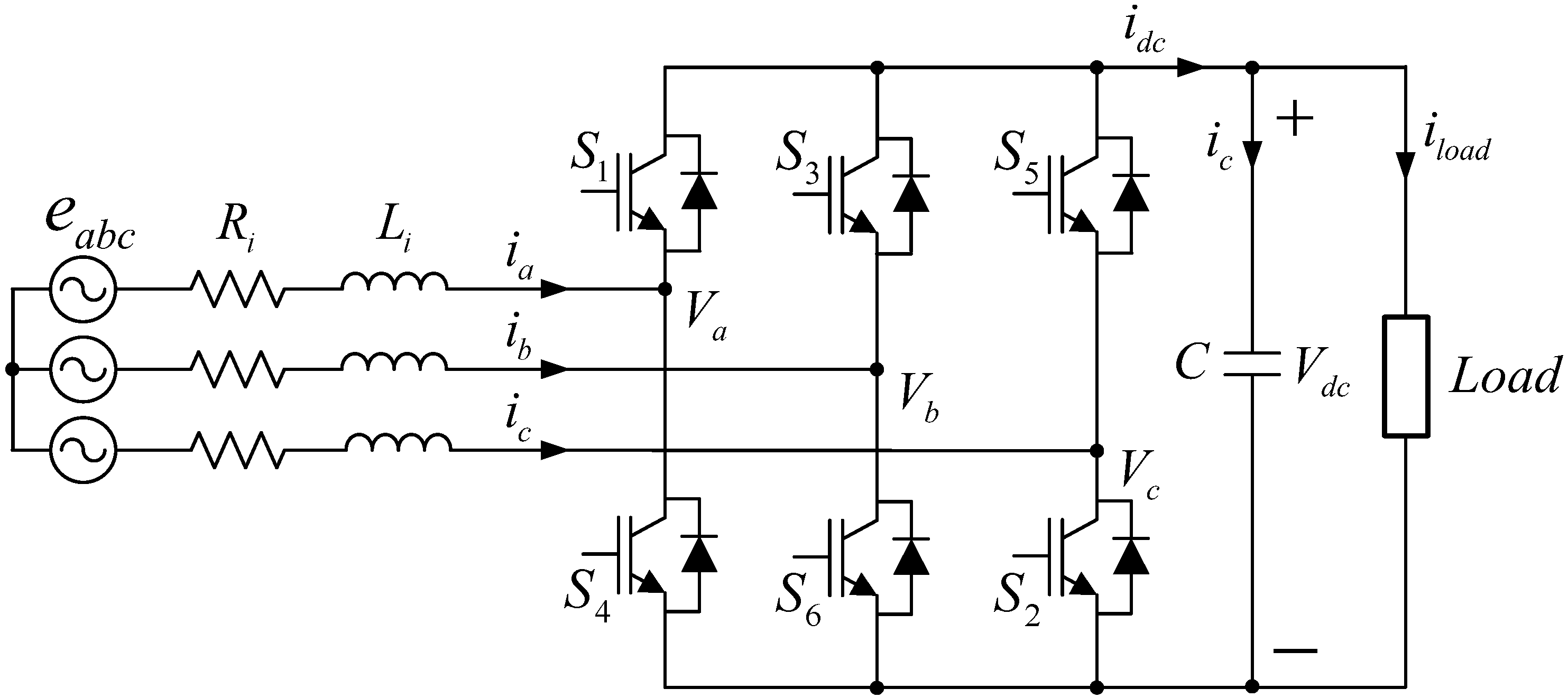
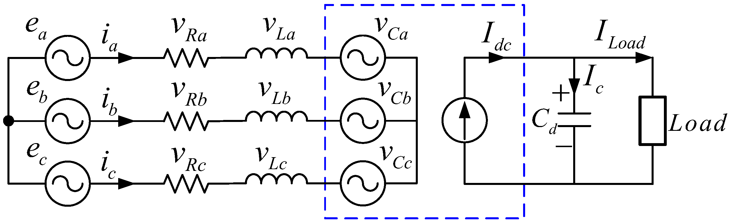
2. 3-Phase AC/DC PWM Converter Used in DC Distribution System

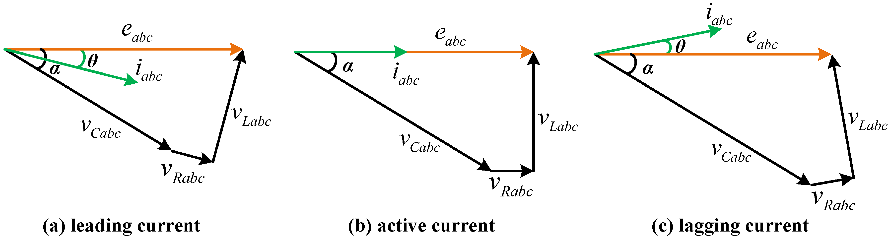
2.1. 3-Phase AC/DC PWM Converter [12,13,14]

The 3-phase AC/DC PWM converter that is used for DC distribution is an AC/DC step-up converter that outputs a boost DC while using an appropriately designed AC input side reactor. Using this 3-phase AC/DC PWM converter, the grid side AC current can be maintained at a waveform that is close to a sinusoidal waveform with a relatively low total harmonic distortion (THD), and the power factor can be freely controlled. In addition, a bi-directional energy flow is possible by using a power semiconductor switch capable with bidirectional power flow, such as IGBT instead of a diode, so it can operate as both a DC/AC inverter and an AC/DC inverter.
Figure 2 shows the equivalent circuit of the 3-phase AC/DC PWM converter that is shown in Figure 1. The AC input voltage of each phase satisfies Equation (1), and the relationship between the input current i a b c and the voltage across the AC input reactor V L a b c is expressed, as shown in Equation (2).
e a b c = v R a b c + v L a b c + v C a b c
v L a b c = j ω L a b c i a b c
As can be seen from Equation (2), increasing the V L a b c increases the AC input side current, i a b c . Conversely, if the value of V L a b c becomes negative, the direction of i a b c is reversed and a regenerating operation is thus performed, the power of which flows from the DC load to the grid side. If the switching loss and harmonic loss of the 3-phase AC/DC PWM converter are ignored, the input power and the DC output power have the relationship that is shown in Equation (3).
V C · C d V C d t = v C a i a + v C b i b + v C c i c = e a i a + e b i b + e c i c
Figure 3 shows a single-phase equivalent circuit of a 3-phase AC/DC PWM converter for analyzing the grid voltage and the current in a phasor diagram. When the converter performs a regenerative operation, the power factor angle of the AC power source in the steady state can be varied from leading to lagging, as shown in the phasor diagram of Figure 4 by controlling the AC side of the 3-phase AC/DC PWM converter. Figure 4 shows that the AC voltage is the smallest when the lagging operation is conducted. If the DC voltage is smaller than the maximum value of the AC input voltage, the constant DC output voltage can be controlled by lagging operation.

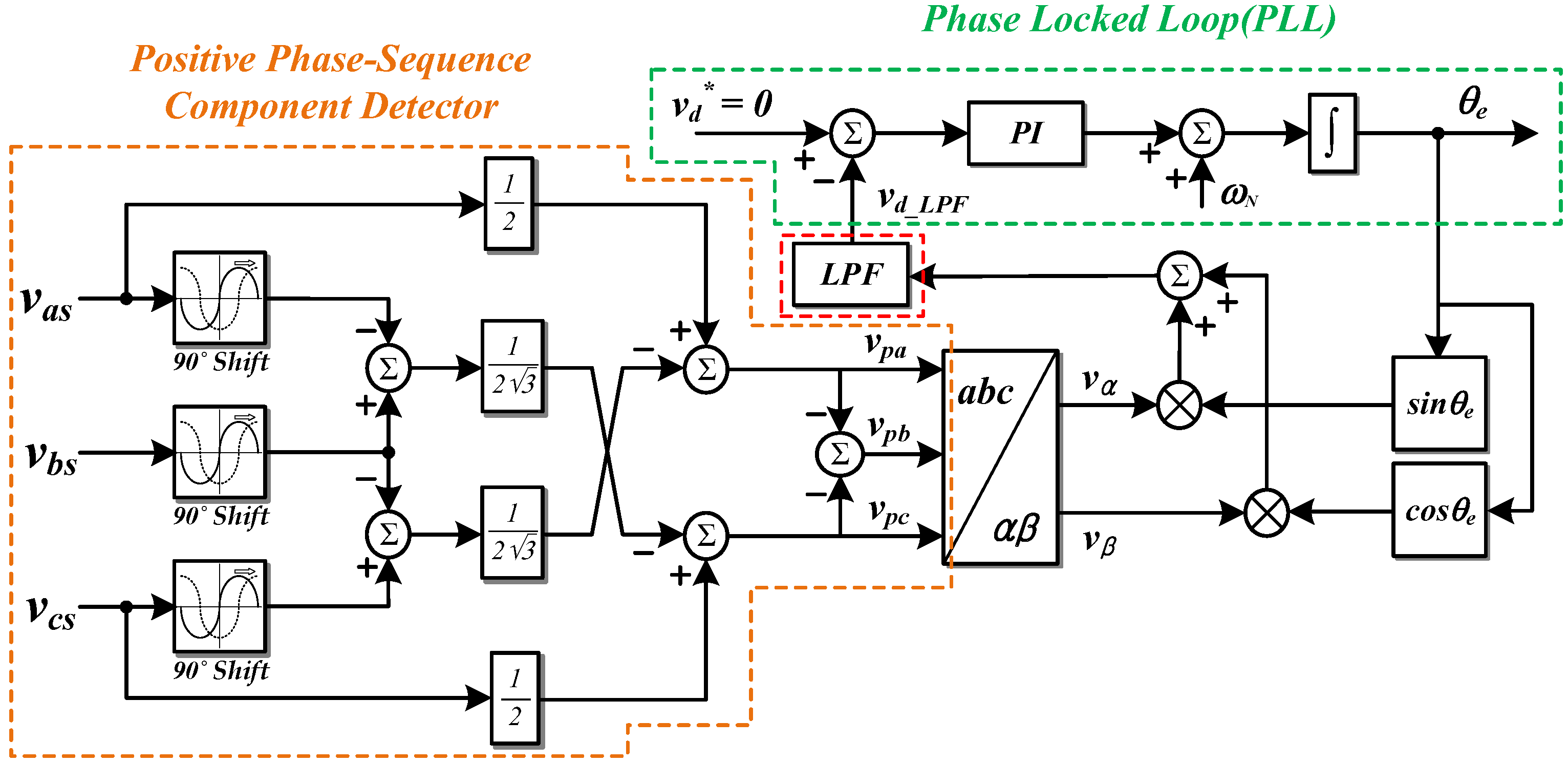
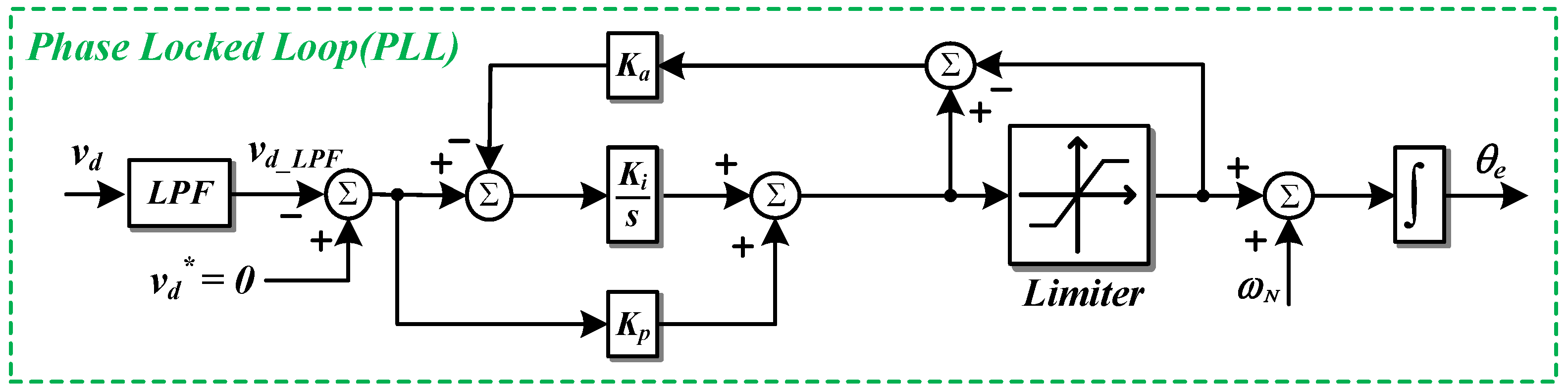
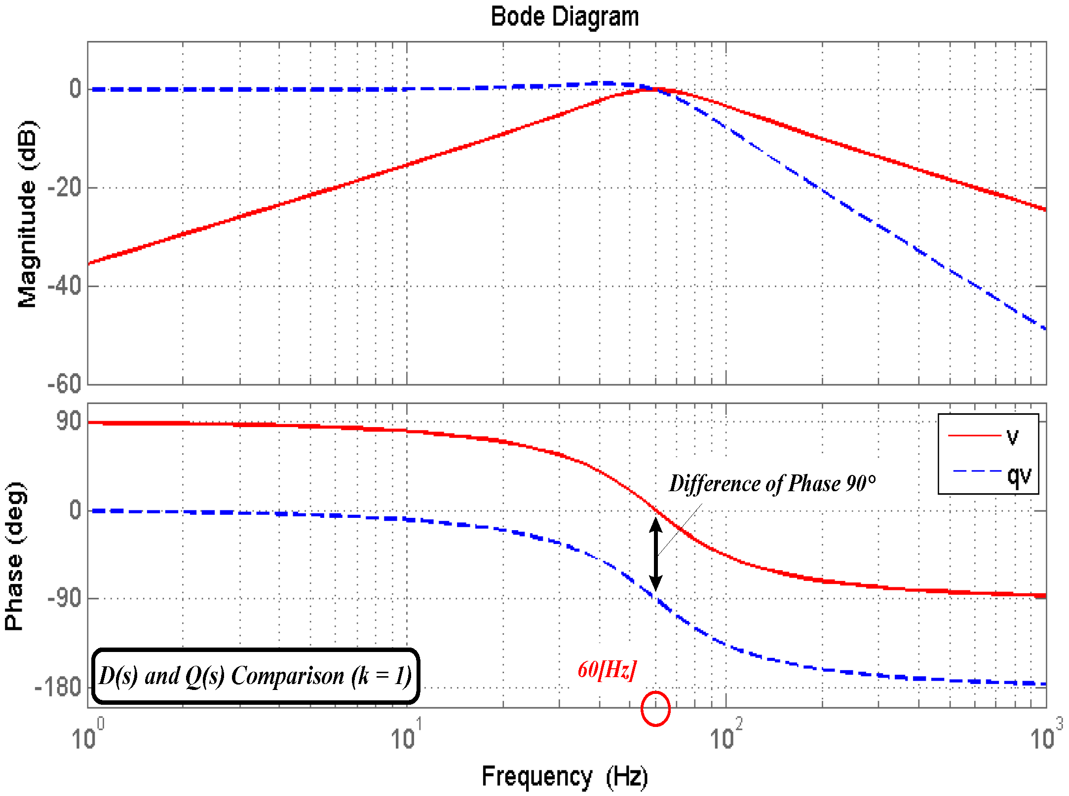
2.2. Positive Sequence Voltage and Phase Detector [15,16]

The phase angle information of the grid is needed in a grid-connected DC distribution system. In the case of power factor control, active/reactive power control, and harmonic current compensation, the current or voltage reference must be synchronized with the phase angle of the input voltage. A PLL is used for this phase synchronization. If the 3-phase power source is balanced, then the phase angle can be obtained by calculating the period between the zero-crossing points where the voltage of one phase or any line-to-line voltage changes from negative to positive. However, in the case of unbalanced 3-phase source, a miscalculated phase angle can result in harmonic components of voltage and current, which can lead to unforeseen problems. To avoid this problem that is caused by the unbalanced 3-phase source, the phase angle is detected by calculating the positive sequence voltage.
The equation for calculating the positive sequence voltage is given by the following Equation (4):
[ v p a v p b v p c ] = 1 3 · [ 1 α α 2 α 2 1 α α α 2 1 ] · [ v a s v b s v c s ]
where α = e j 2 π 3 = 1 2 + j 3 2 and α 2 = e j 4 π 3 = 1 2 j 3 2 .
α and α 2 can be substituted into Equation (4), and Equation (5) is then defined, as follows:
[ v p a v p b v p c ] = [ 1 2 v a s 1 2 3 j ( v b s v c s ) ( v p a + v p c ) 1 2 v c s 1 2 3 j ( v a s v b s ) ]
Figure 5 shows the control block diagram of the positive sequence voltage and PLL while using Equations (4) and (5). As shown in the figure, the d-q transformation is performed after extracting the positive sequence voltage while using the 3-phase voltage of the input power source. In the d-q transformation, the information on the q axis refers to the magnitude of the voltage output of the converter, and the information on the d axis is related to the phase error between the converter output voltage and the grid voltage. Therefore, the phase output voltage of the converter must control the d-axis voltage to zero for phase synchronization with the grid voltage. The d-axis voltage in the synchronous reference frame, as calculated by the PI controller, then performs a PLL that controls the phase angle to be zero so that the phase angle matches the actual phase angle of the grid side. When the input power source includes harmonics due to noise, the harmonics also appear in the d-axis voltage used as an input of the PLL. Therefore, as shown in Figure 6, the first order low pass filter is used to prevent pulsation.

3. Proposed Control Scheme of 3-Phase AC/DC PWM Converter Using SOGI-FLL

In the conventional PLL method that is discussed in Section 2.2, the sensed 3-phase input voltage is divided into magnitude and phase angle information by d-q transformation and the d-axis voltage in the synchronous reference frame is used to obtain phase angle information. However, the conventional PLL method is difficult to use in single-phase systems. In addition, if the cut-off frequency of the low pass filter is decreased to reduce the low frequency harmonics of the input power source, the total control bandwidth of the PLL will be reduced, which is disadvantageous to the sudden change of phase angle [17].
Therefore, this section describes the FLL method using SOGI, which is applicable to both single-phase and 3-phase systems and has excellent performance for low frequency harmonics reduction [18,19,20]. This section also introduces a method of detecting positive sequence voltage while using SOGI-FLL and it describes the design of the controller.

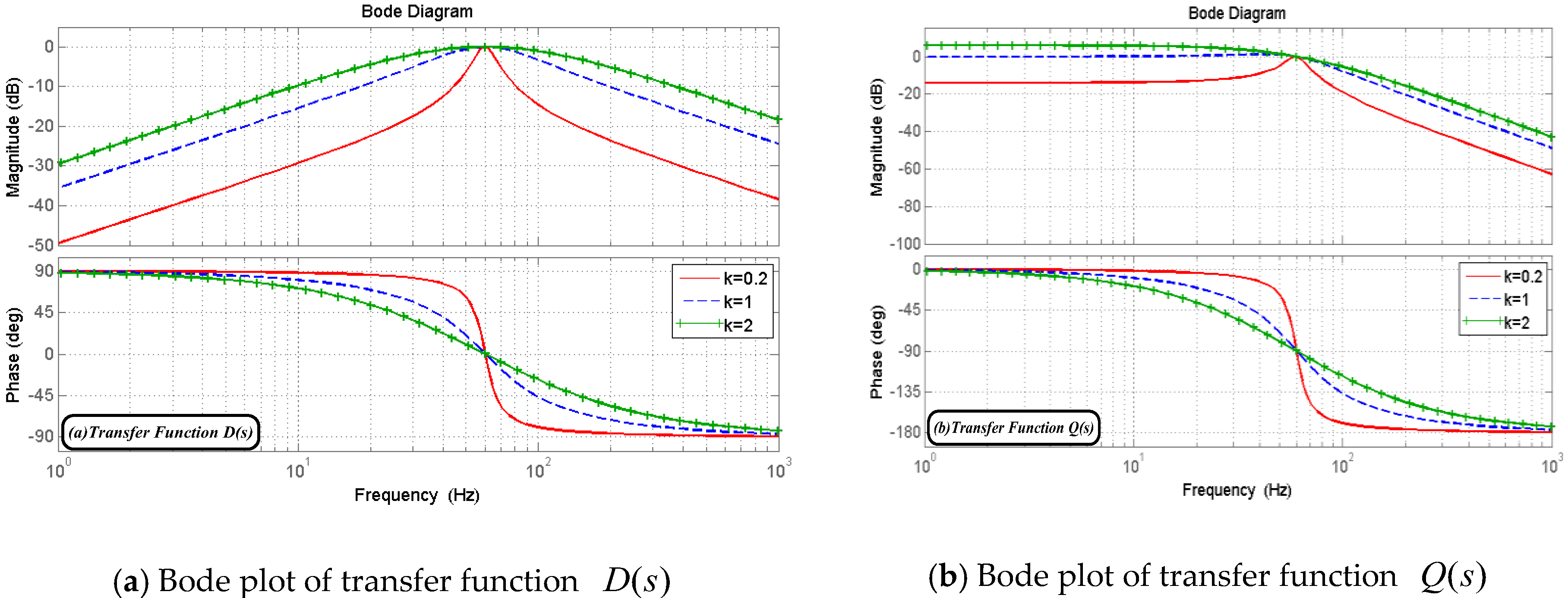
3.1. Second Order Generalized Integrator

Figure 7 shows the structure of the SOGI-based adaptive filter (AF) in a control block diagram [21]. The transfer function of the SOGI that is shown in Figure 7 can be expressed as Equation (6), and the transfer function for the output signals v and q v of the SOGI-based AF is defined as Equation (7). As can be seen from the transfer function D ( s ) in Equation (7), the bandwidth of the SOGI-based AF is independent of the frequency ω and it is only determined by the gain k . Also, the output signal q v generates a signal that is delayed by 90 degrees from the phase of the output v , irrespective of the frequency of the center frequency ω and the input signal v . Therefore, Equation (7) can be expressed as the bode plot as shown in Figure 8.
S G ( s ) = v k ε v ( s ) = ω s s 2 + ω 2
D ( s ) = v v ( s ) = k ω s s 2 + k ω s + ω 2 , Q ( s ) = q v v ( s ) = k ω 2 s 2 + k ω s + ω 2
Figure 9 shows the bode plot of the transfer function of Equation (7). From the figure, it can be seen that as the gain k decreases, the filtering effect improves, but the stability according to the frequency change decreases. The SOGI-based AF, as shown in Figure 7, is also called the SOGI-quadrature signal generator (SOGI-QSG).

3.2. SOGI-FLL

SOGI-FLL is used for detecting input voltage exactly, even if input frequency is varied and due to grid distortion or fault. Configuration and discretization of the SOGI-FLL technique in single-phase grid-connected inverter system is introduced in [22]. In this subsection, not only introducing the structure of SOGI-FLL, but also how SOGI-FLL extracts information of input voltage and tracks frequency variation based on its mathematical explanation and bode plot. If the center frequency ω is set to the same frequency as the input signal, the SOGI-based AF outputs v having the same amplitude and phase as the input signal and q v delayed only by 90 degrees from the input signal. However, if the frequency of the input signal varies, the amplitudes of v and q v is changed. Therefore, it is not appropriate to use SOGI only for power conversion systems that use AC power such as grid-connected systems. In order to apply SOGI to a system where the input frequency is possibly changed, the center frequency must be able to follow the frequency change of the input signal.
In the FLL method, frequency information is extracted using the phase delayed signal of SOGI q v , which is used as the center frequency ω of SOGI. FLL can be operated without the PI controller and trigonometric function calculations that were used in PLL. Figure 10 shows the control block diagram of SOGI-FLL, where ω N is the angular frequency of the input voltage in steady state, as used in the PLL.
In order to explain the SOGI-based AF with FLL, the error signal ε v , which is the relation between the output signals q v , v , and v , should be analyzed. The transfer function for the input signal v and the error signal ε v is shown in Equation (8).
E ( s ) = ε v v ( s ) = s 2 + ω 2 s 2 + k ω s + ω 2
The transfer function E ( s ) is illustrated in the bode plot that is shown in Figure 11.
As shown in Figure 11, if the frequency of the input signal ω is lower than the center frequency ω , q v , and ε v have the same phase. That is, the frequency error variable ε f can be calculated using the two signals q v and ε v . If ω < ω , then ε f is a positive value, if ω = ω then ε f = 0 and if ω > ω then ε f is a negative value. This means that the negative gain γ and the integrator expressed in Figure 10 are used to set the DC component of the frequency error variable ε f to zero so that the center frequency ω tracks the frequency of the input signal ω .
To use this SOGI-FLL in 3-phase systems, two SOGIs are used. This is called a double second order generalized integrator (DSOGI). Figure 12 shows a control block diagram of the DSOGI-FLL that is used in the 3-phase AC system.

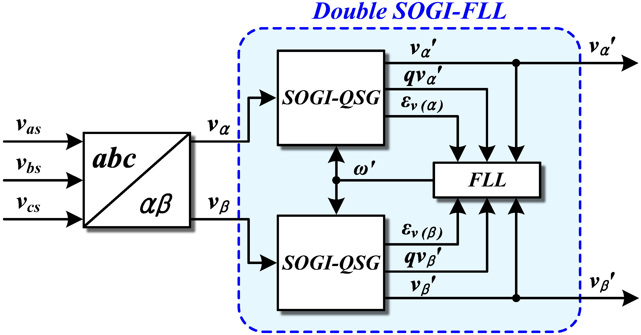
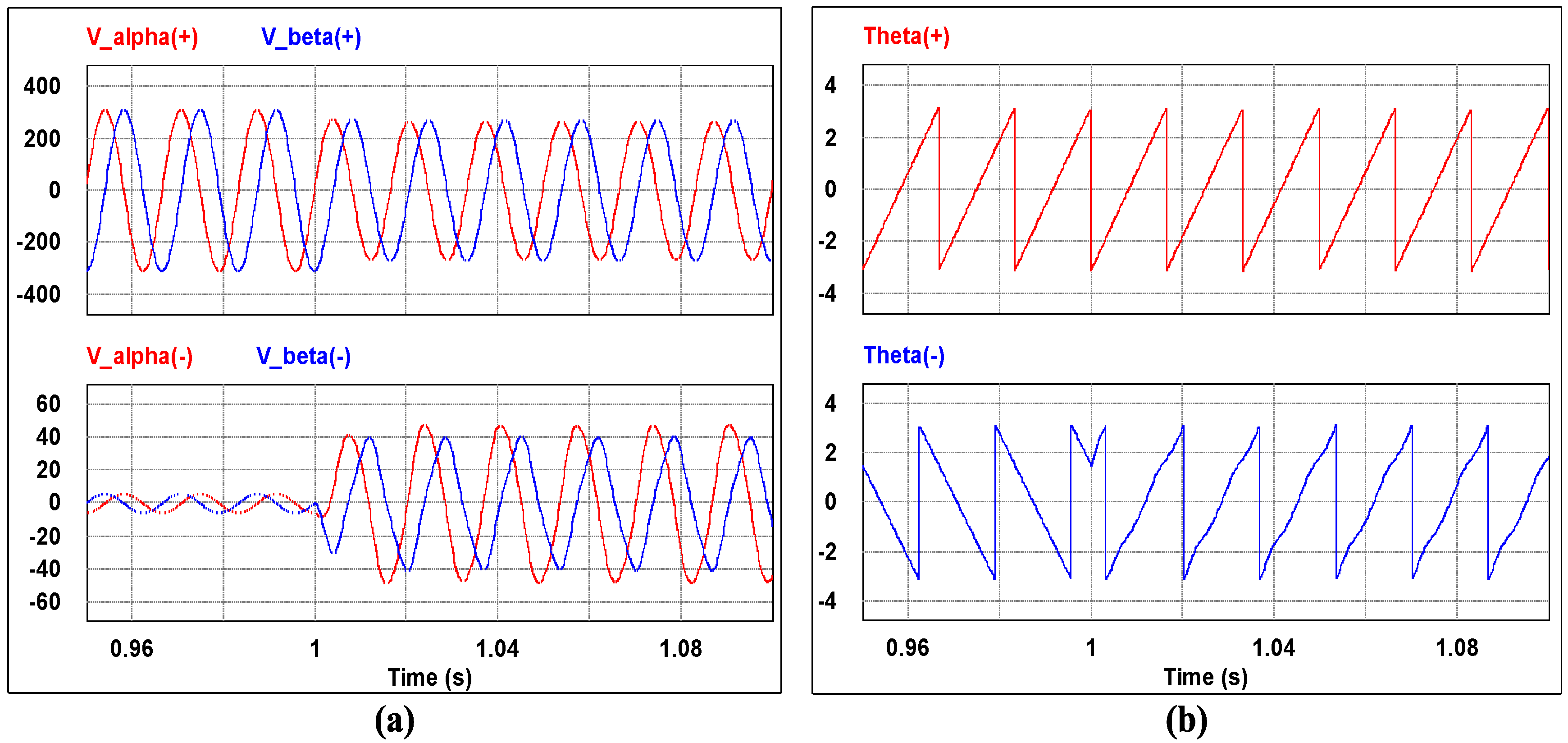
3.3. Positive Sequence Voltage Extraction and Phase Detection Using 3-Phase SOGI-FLL

In 1937, Lyon proposed a method for decomposing balanced 3-phase voltages v a , v b , and v c into positive, negative, and zero sequence voltage in the time domain, respectively, while in 1918, Fortescue proposed a method in the frequency domain [23]. Using these methods, the balanced 3-phase voltage is decomposed into positive, negative, and zero sequence voltages, as shown in Equations (9)–(11), respectively.
[ v a + v b + v c + ] = 1 3 · [ 1 α α 2 α 2 1 α α α 2 1 ] · [ v a v b v c ]   ( v a b c + = [ T + ] · v a b c )
[ v a v b v c ] = 1 3 · [ 1 α 2 α α 1 α 2 α 2 α 1 ] · [ v a v b v c ]   ( v a b c = [ T ] · v a b c )
[ v a 0 v b 0 v c 0 ] = 1 3 · [ 1 1 1 1 1 1 1 1 1 ] · [ v a v b v c ]   ( v a b c 0 = [ T 0 ] · v a b c )
where α = e j 2 π 3 = 1 2 + j 3 2 and α 2 = e j 4 π 3 = 1 2 j 3 2 .
3 × 3 matrices in each equation can be expressed as [ T + ] , [ T ] , and [ T 0 ] . If the balanced 3-phase voltage is transformed to the voltage in the stationary reference frame, it can be defined as Equation (12). Equation (12) is then simplified to Equation (13), with the assumption that no zero sequence components exist in the balanced 3-phase voltage.
[ v α v β v 0 ] = 2 3 · [ 1 1 2 1 2 0 3 2 3 2 1 2 1 2 1 2 ] · [ v a v b v c ] v α β 0 = [ T α β 0 ] · v a b c
[ v α v β ] = 2 3 · [ 1 1 2 1 2 0 3 2 3 2 ] · [ v a v b v c ] v α β = [ T α β ] · v a b c
The transpose matrix [ T α β ] is given by the following Equation (14).
[ T α β ] T = 3 2 · [ 2 3 0 1 3 3 3 1 3 3 3 ]
Using Equations (9)–(14), the positive and negative sequence voltages in the stationary reference frame can be summarized, as shown in Equations (15) and (16).
v α β + = [ T α β ] · v a b c + = [ T α β ] · [ T + ] · v a b c = [ T α β ] · [ T + ] · [ T α β ] T · v α β = 1 2 · [ 1 q q 1 ] · v α β
v α β = [ T α β ] · v a b c = [ T α β ] · [ T ] · v a b c = [ T α β ] · [ T ] · [ T α β ] T · v α β = 1 2 · [ 1 q q 1 ] · v α β
In Equations (15) and (16), q = e j π 2 , which indicates that the phase is delayed by 90 degrees. In this case, the positive and negative sequence voltage extractors are added. Figure 12 is then modified, as shown in Figure 13.

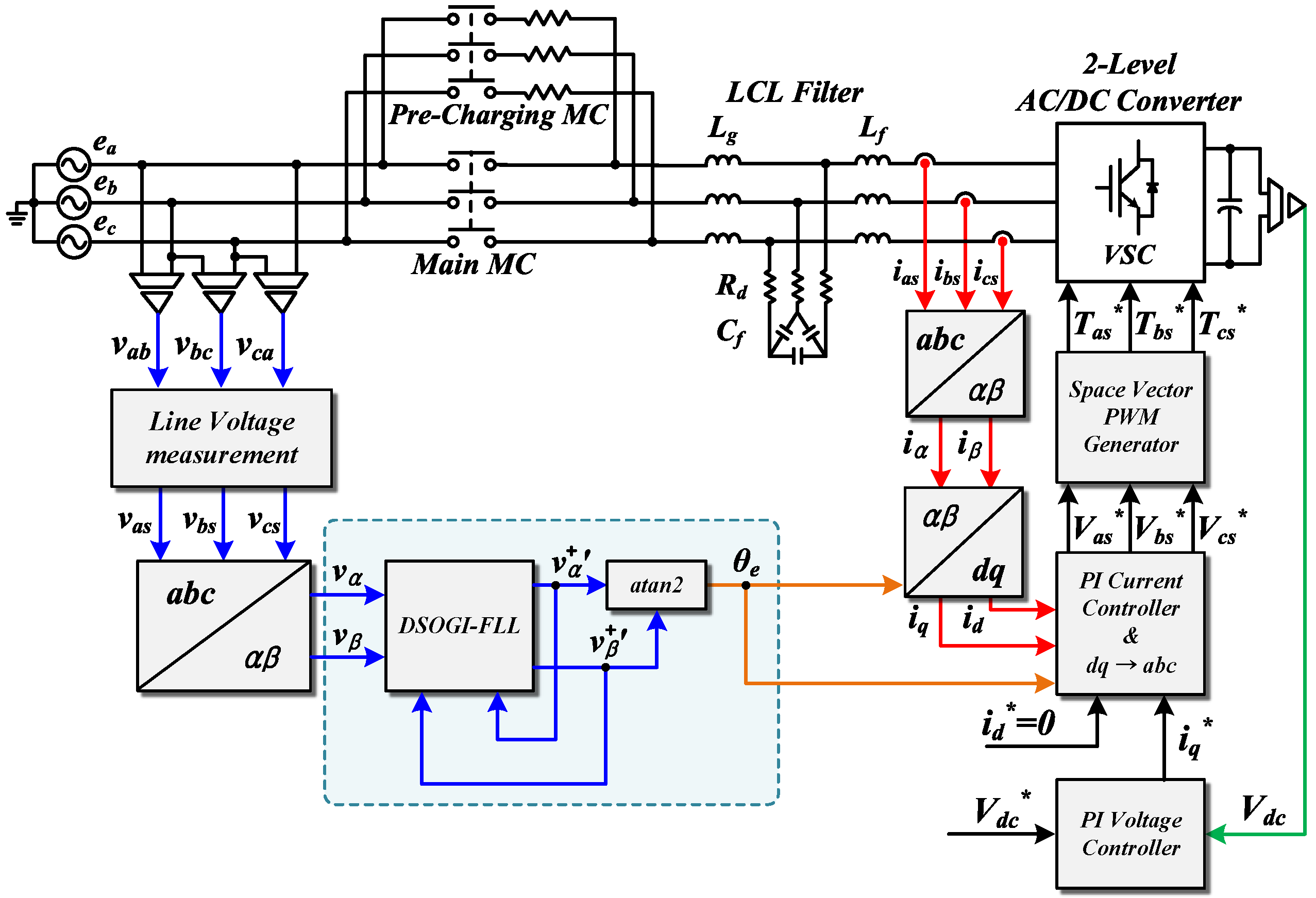
3.4. Control Block Diagram of Overall System with SOGI-FLL

Figure 14 shows the overall control block diagram of the proposed control scheme. Similar to the conventional control method, each line-to-line voltage of the grid is sensed and transformed to a stationary reference frame. The phase angle information is then extracted while using DSOGI-FLL. The coordinate of the input current of the 3-phase AC/DC PWM converter is transformed using the extracted phase angle derived from DSOGI-FLL. At this time, the output of the PI voltage controller that controls the dc-link voltage is applied to the input of the PI current controller that controls the active and reactive power of the grid. When the output of the current controller performs an inverse d-q transformation, an extracted phase angle using DSOGI-FLL is also used.
As can be seen from the control block diagram, when using the proposed control scheme, the coordinate transformation is simpler than the control method while using the conventional PLL. In addition, the low pass filter that affects the bandwidth of the controller disappears in the proposed control method.

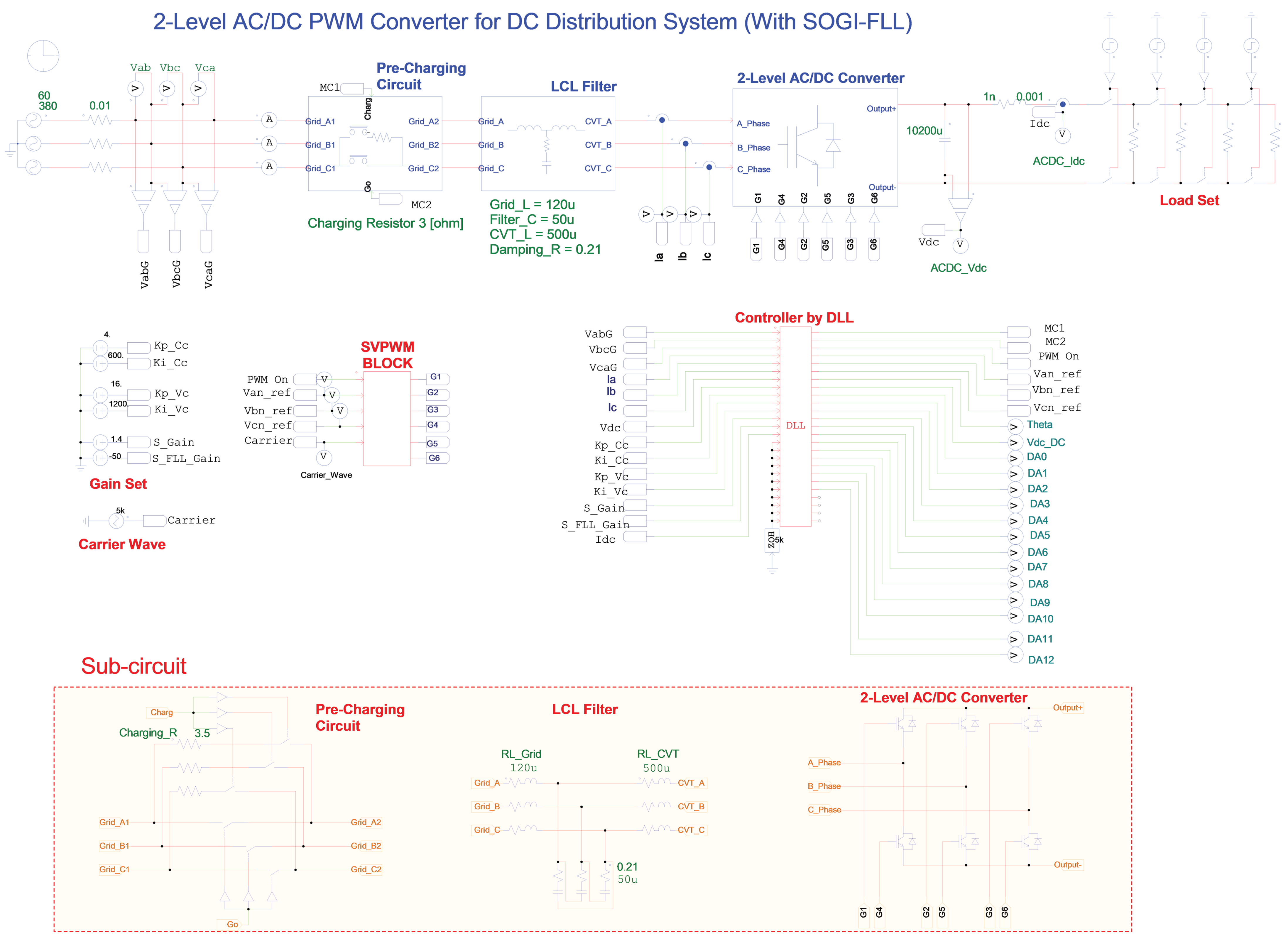
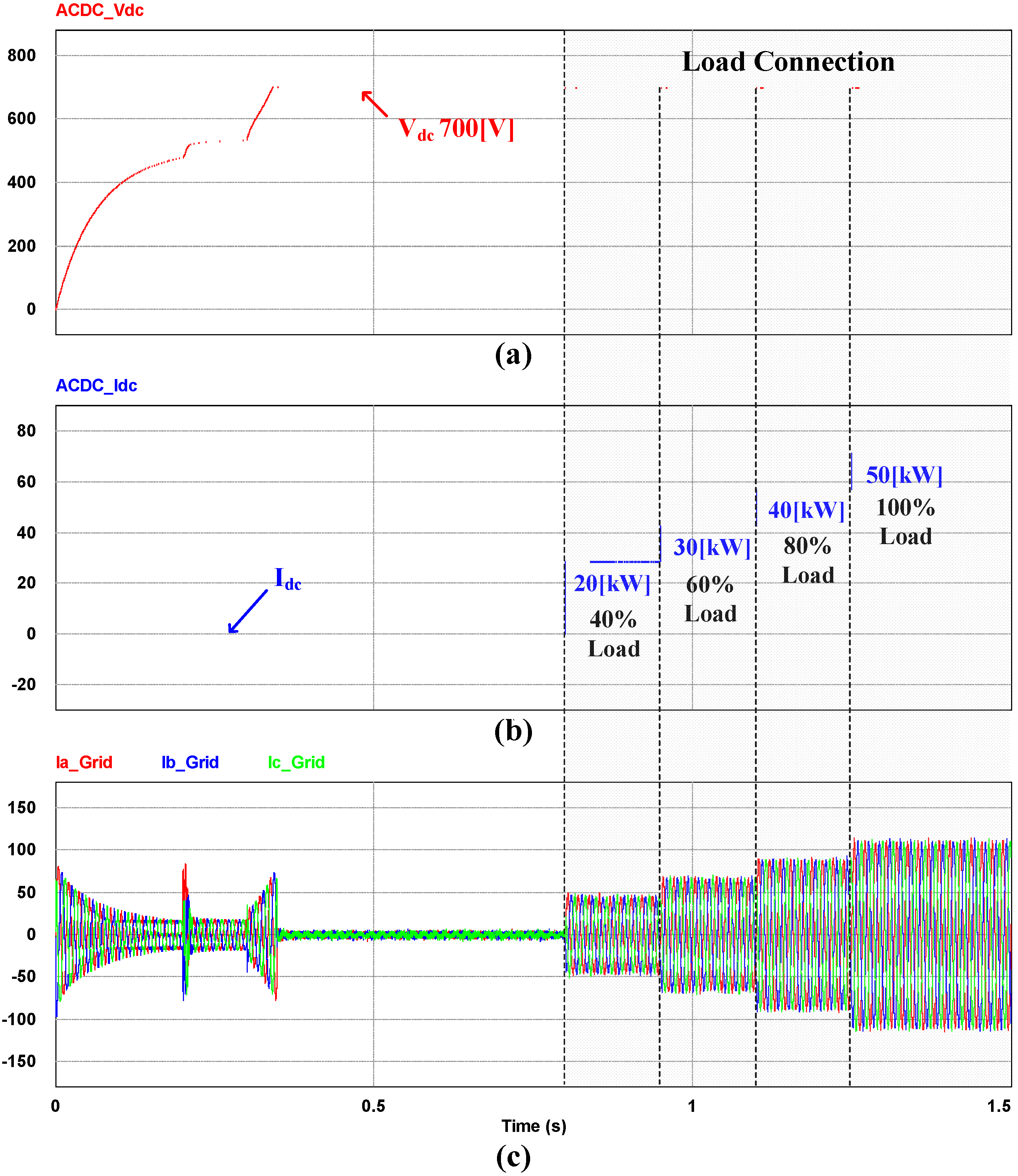
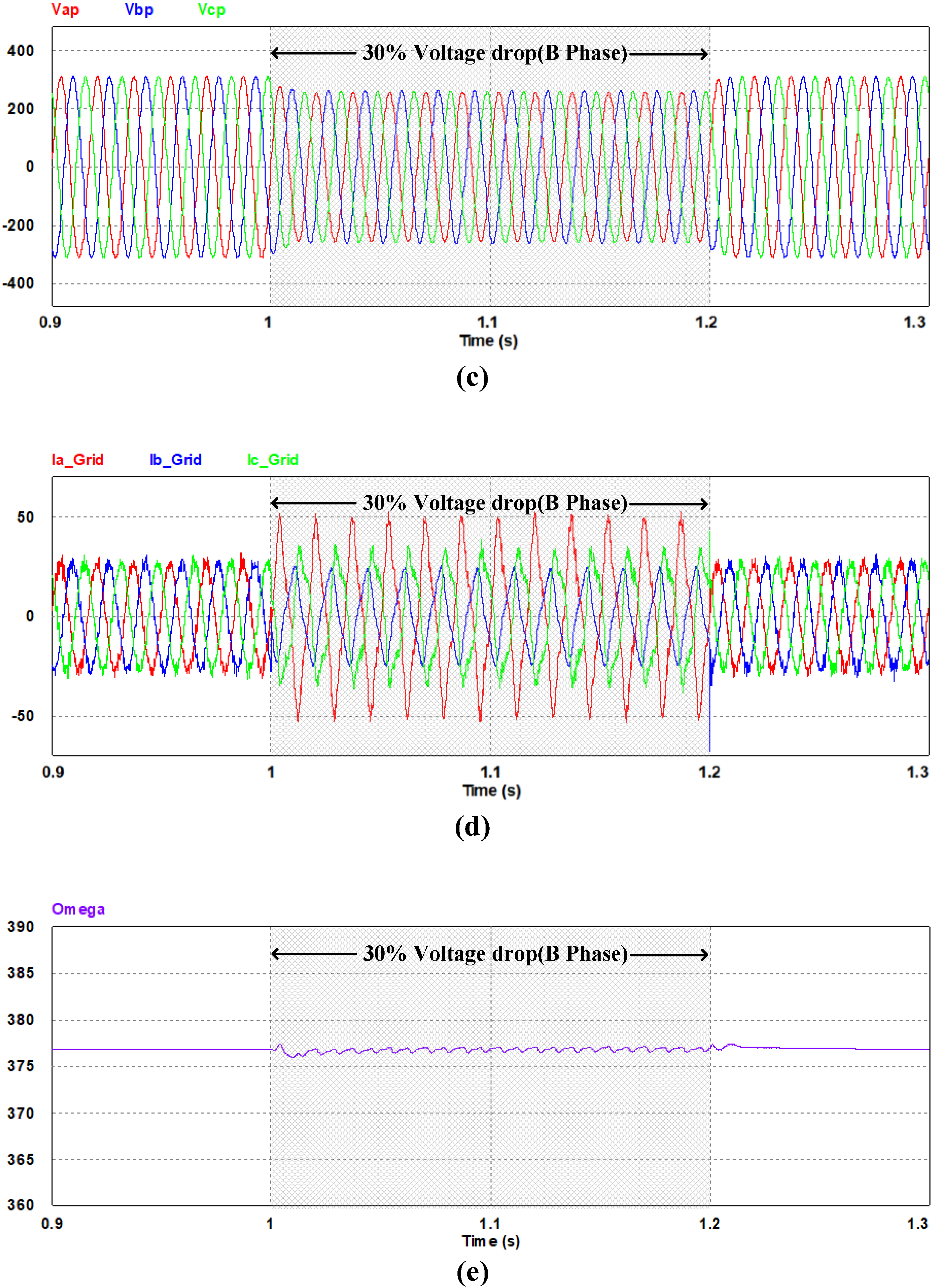
4. Simulation Results

In this paper, the simulation was performed before verifying the operation of the 3-phase AC/DC PWM converter with the SOGI-FLL method for the DC distributed system. Table 1 shows the parameters that are used in the simulation, while the configuration of the simulation circuit is shown in Figure 15. In the existing AC power grid, the power from the power plant is supplied to the consumer in single phase 220 Vrms and 3-phase 380 Vrms. Therefore, the 3-phase voltage is selected, as shown in the parameter. Also, when configuring of the DC distribution system, the DC-link voltage was selected as 700 Vdc, which is capable of meeting the scope of international electrotechnical commission (IEC) regulations [24]. The switching frequency is selected in consideration of the FS300R12KE3, which IGBT are used in this system, and the LCL filter are designed to satisfy the current distortion regulation of the IEEE ST 519-2014.
Figure 16a shows the output voltage waveform of a DC distribution system while using a 3-phase AC/DC PWM converter. The system uses an initial charge circuit that charges a certain amount of voltage to the output capacitor for 0.2 s to reduce the inrush current entering the output capacitor. Then, the charge of the capacitor voltage increases, while the initial charge circuit is changed from the initial charge to a standby condition. Finally, an output voltage control of 700 Vdc is initiated from 0.3 s. In order to prevent the high overshoot of the output voltage at the start of the control, the voltage reference is given in the form of a ramp. The voltage reference then rapidly enters the steady state due to the fast dynamic characteristics of the PI controller.
Figure 16b shows the output current waveform after connecting the DC link output to the load. The load is connected to the system from 0.8 s and the load capacity is increased by 10 kW every 0.15 s. Finally, a current is stably generated at the system rated capacity of 50 kW.
Figure 16c shows the 3-phase input current waveform from the grid to the system. It is confirmed that the reactive component rarely flows when no load is applied, and the magnitude of the input current increases step by step when the load is connected.
Figure 17a shows the 3-phase input voltage waveforms containing the 3rd, 5th, 7th, 9th, and 11th harmonics. The input voltage is detected through the sensor and is then input to the controller. The SOGI-FLL is applied to the system controller in the middle of the α β d q coordinate transformation, and the output voltage of the SOGI-FLL indicates that the harmonics are reduced, as shown in Figure 17b. The THD of the detected positive sequence voltage is about 3.9%, which is appropriate for the phase angle detection.
Figure 18 shows the waveforms when a voltage drop of about 30% occurs on the b phase. Figure 18a shows the dc-link output voltage waveform. A voltage ripple of about 2 [Vpeak-to-peak] is generated while voltage drop occurs. Figure 18b shows the unbalanced 3-phase input voltage waveform. The balanced 3-phase condition is distorted by the voltage drop from 1 to 1.2 s. Figure 18c shows the detected positive sequence voltage waveform using SOGI-FLL. Unlike that shown in Figure 18b, the magnitude of voltage is slightly reduced and it maintains a balanced 3-phase condition. The 3-phase input current waveform is illustrated in Figure 18d. Unlike the voltage in Figure 18b, the changes in the amplitudes of the phases differ, and the shape of the waveform is severely distorted. Figure 18e shows the center frequency ω extracted from SOGI-FLL. Only a slight ripple is generated, and it does not significantly differ from the frequency value in the steady state.
Figure 19 shows the positive and negative sequence voltages and the phase angle generated by SOGI-FLL. While only negligible negative sequence voltage occurs before the unbalance condition, the negative sequence voltage increases immediately after the unbalance condition. In addition, while the phase angle of the positive sequence voltage is stably tracked, the phase angle of the negative sequence component is rapidly changed.
Figure 20 shows the waveforms when the grid frequency decreased from 60 Hz to 45 Hz. Grid frequency is reduced to 45 Hz from 1 to 1.2 s, while the power is supplied to the 12 kW load, and the grid frequency is then recovered to 60 Hz. Figure 20a shows that the dc-link output voltage waveform maintains an almost constant voltage, even when the frequency decreases. Figure 20b shows the 3-phase input voltage waveform. When the frequency is decreased from 1 to 1.2 s, the period increases. Figure 20c shows the positive sequence voltage waveform that was detected by SOGI-FLL. As shown in Figure 20b, since only negligible distortion occurs in the voltage, only the period changes without large amplitude change. Figure 20d shows the 3-phase input current waveform. It can be seen that, while the input current also only changes the period, it but does not cause large distortion. Figure 20e shows the center frequency ω , as extracted from SOGI-FLL. As soon as the grid frequency changes, the FLL follows the grid frequency and synchronizes the output center frequency to the grid frequency. The FLL gain value is designed considering the frequency tracking time of 0.1 s, but the steady state takes slightly more time than the designed time due to the change of the grid conditions.
In Figure 21, the conventional synchronous reference frame-phase locked loop (SRF-PLL) method [25] and SOGI-FLL method are compared to each other when the 3-phase grid voltage frequency is decreased from 60 Hz to 45 Hz. During power supply to 50 kW load, the grid frequency decreases to 45 Hz from 1 to 1.2 s, and then recovers to 60 Hz.
Figure 21a shows that the d -axis voltage in a synchronous reference frame oscillates significantly when the grid frequency changes, and the dc-link voltage oscillation ranges from ± 0.5 to 0.9 Vdc. This oscillation of dc-link output voltage has the potential to adversely affect both the load and the dc-link capacitor. The oscillation occurs because the bandwidth of the controller is low due to the low cut-off frequency of the low pass filter. While this problem can be solved by increasing the cut-off frequency, the low frequency harmonics cannot be blocked.
On the other hand, in the voltages in the synchronous reference frame using SOGI-FLL, as shown in Figure 20b, no oscillation occurs in the d -axis voltage during the frequency change, and the transient state of the dc-link voltage is improved by about 50%.
As a result, the conventional SRF-PLL method takes a long time to stabilize the overshoot of the d -axis current controller in case of a frequency change because of the bandwidth problems in the controller due to digital filters, however, the proposed control method that is based on SOGI-FLL does not use these digital filters, so it is possible to stable and fast transient control.

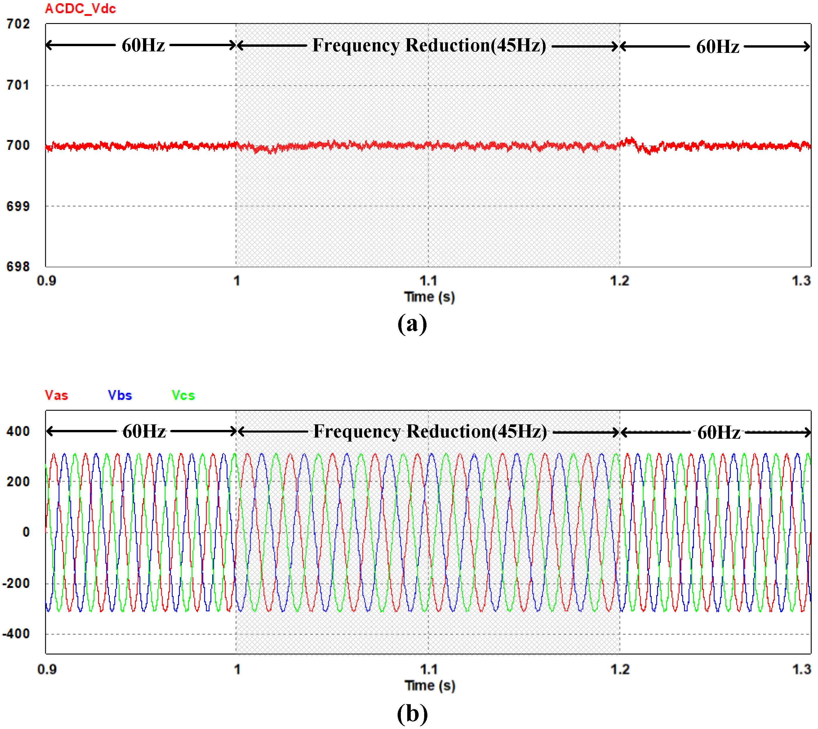
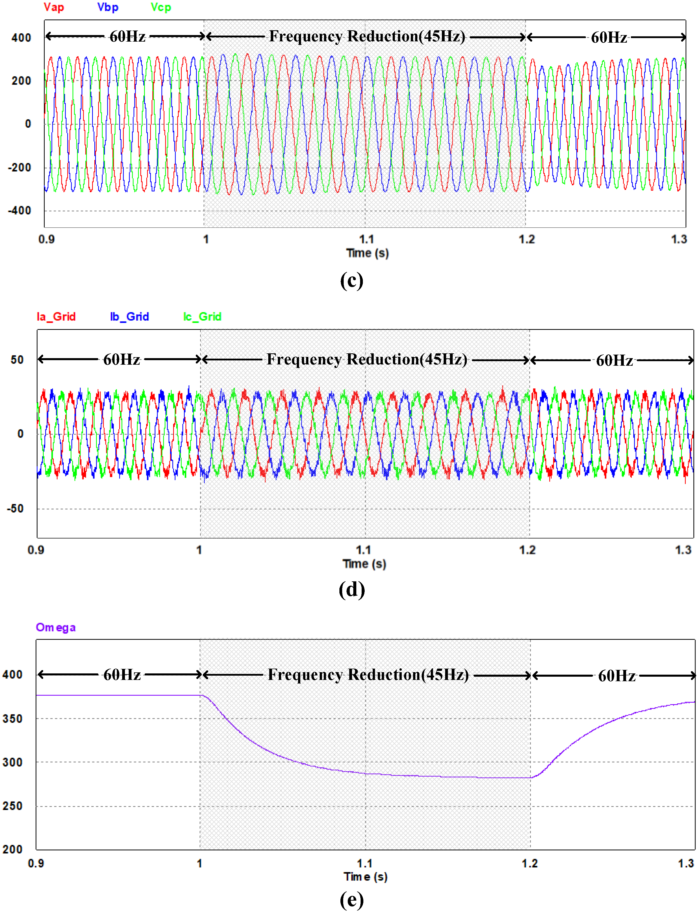
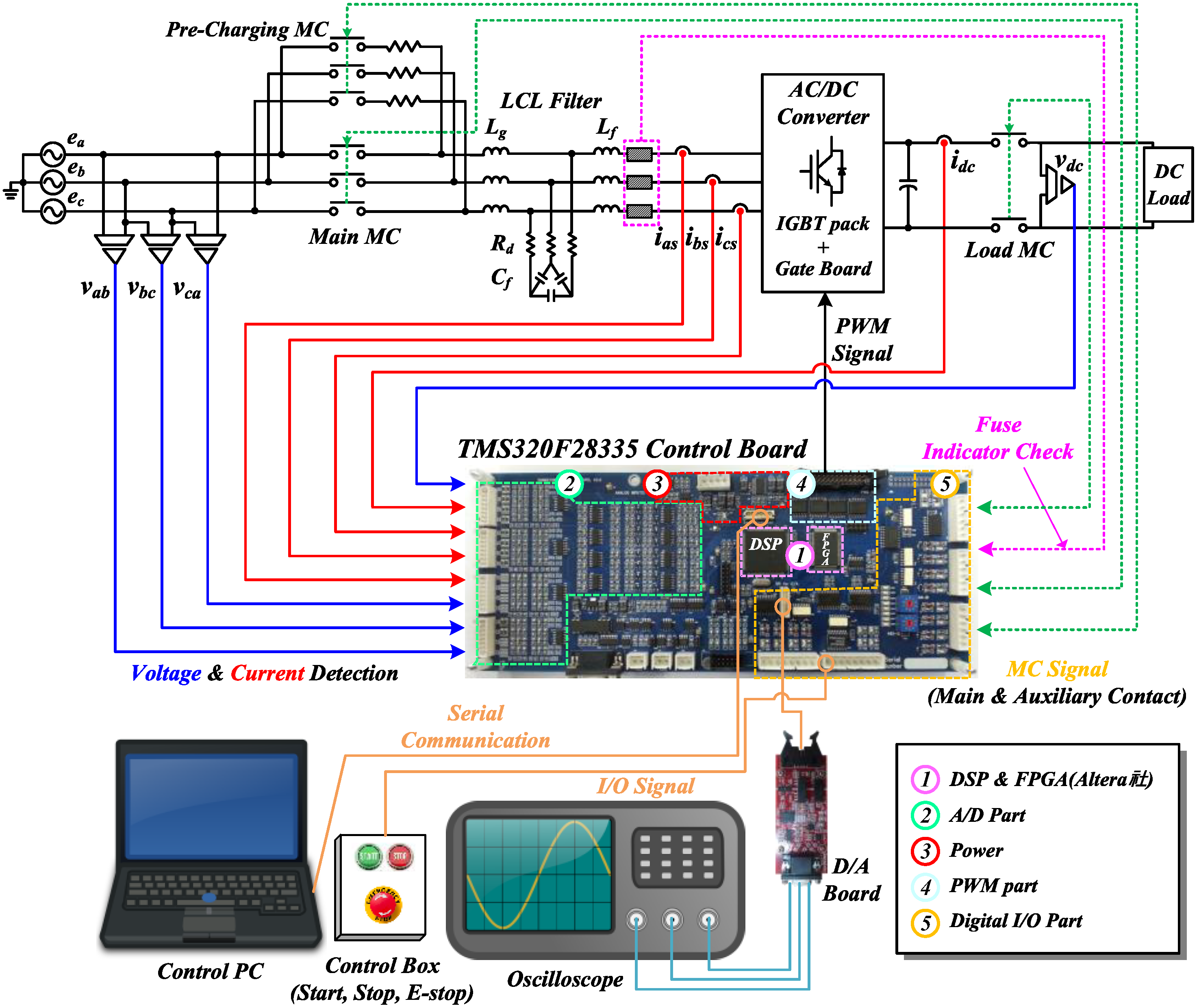
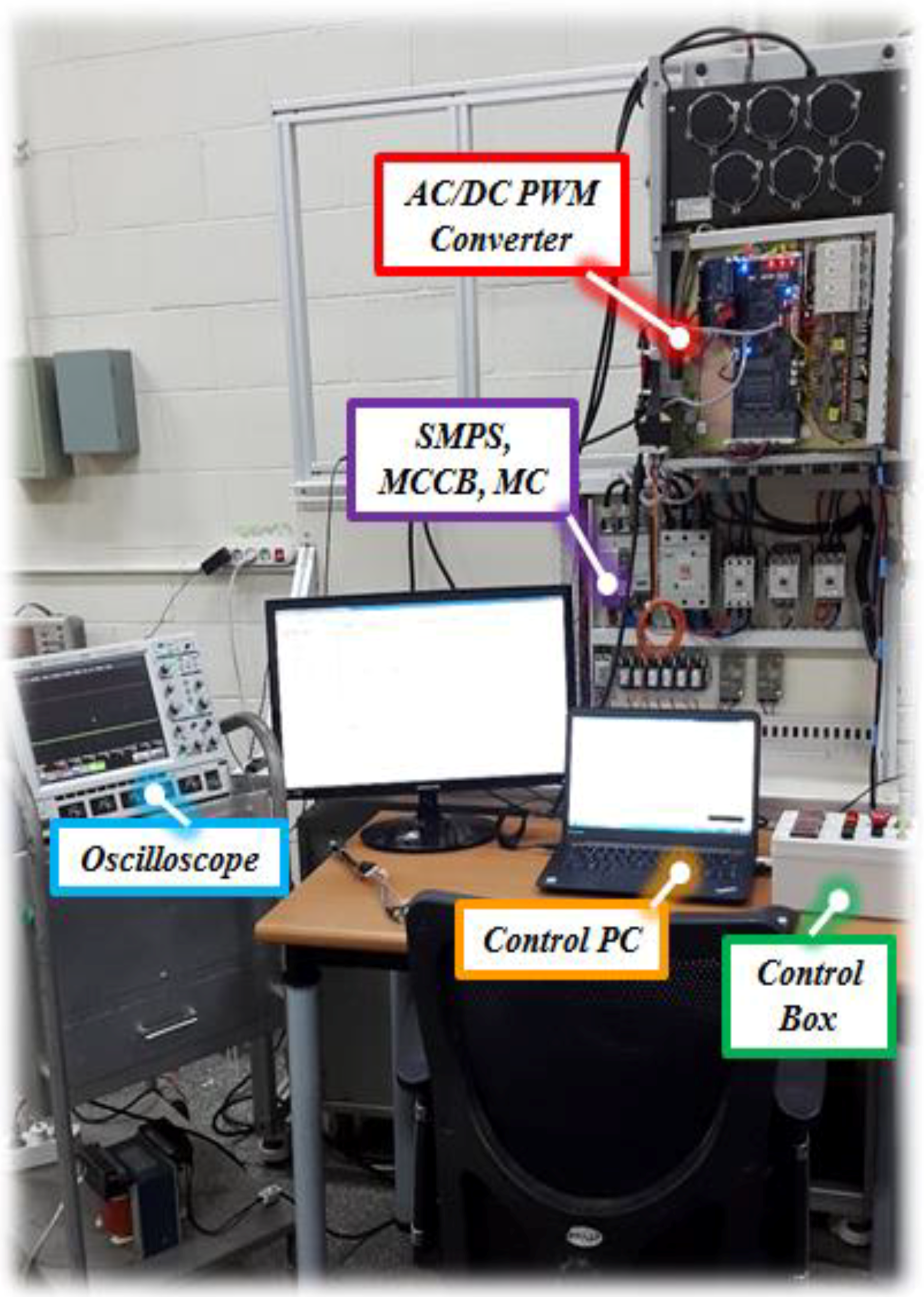
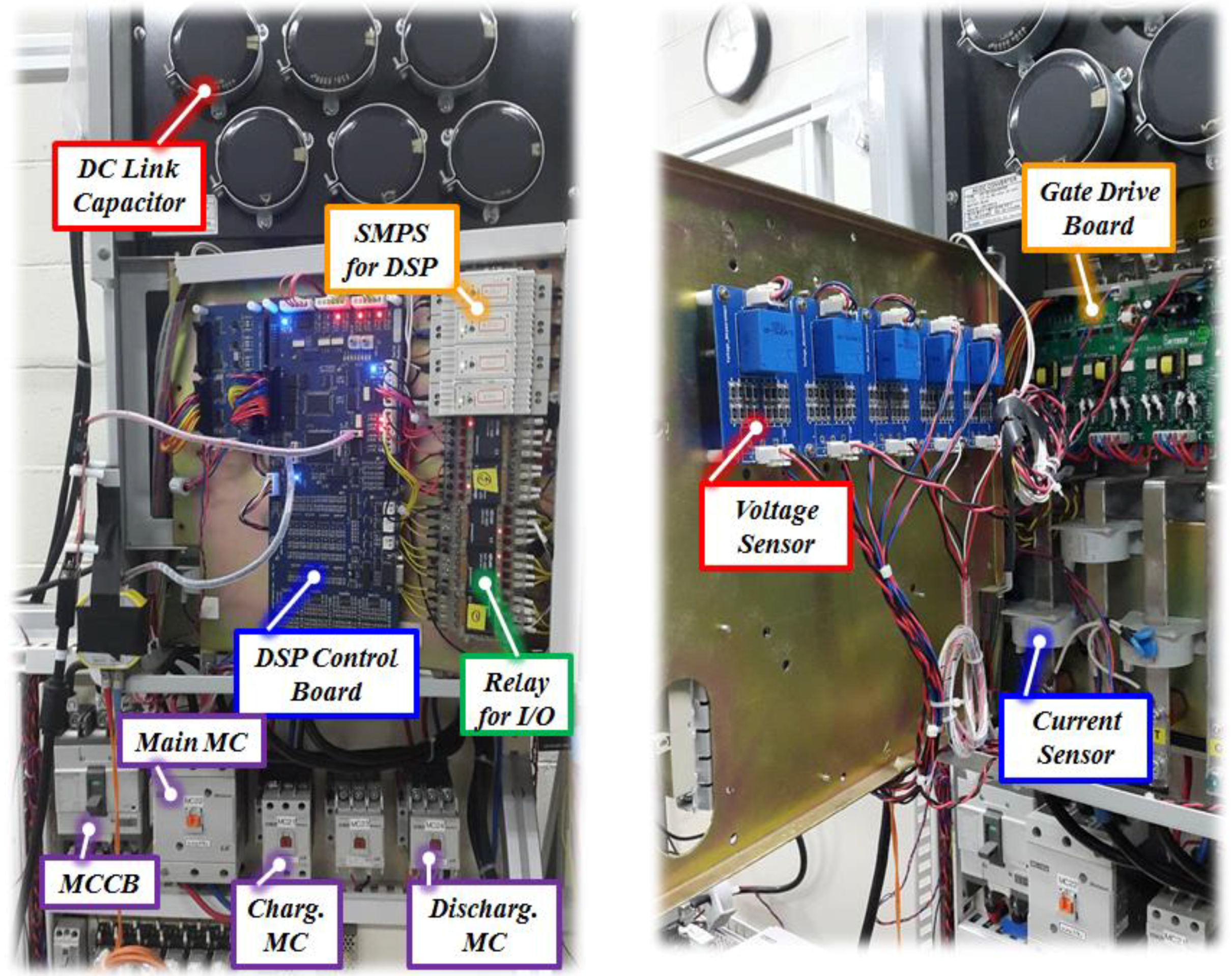
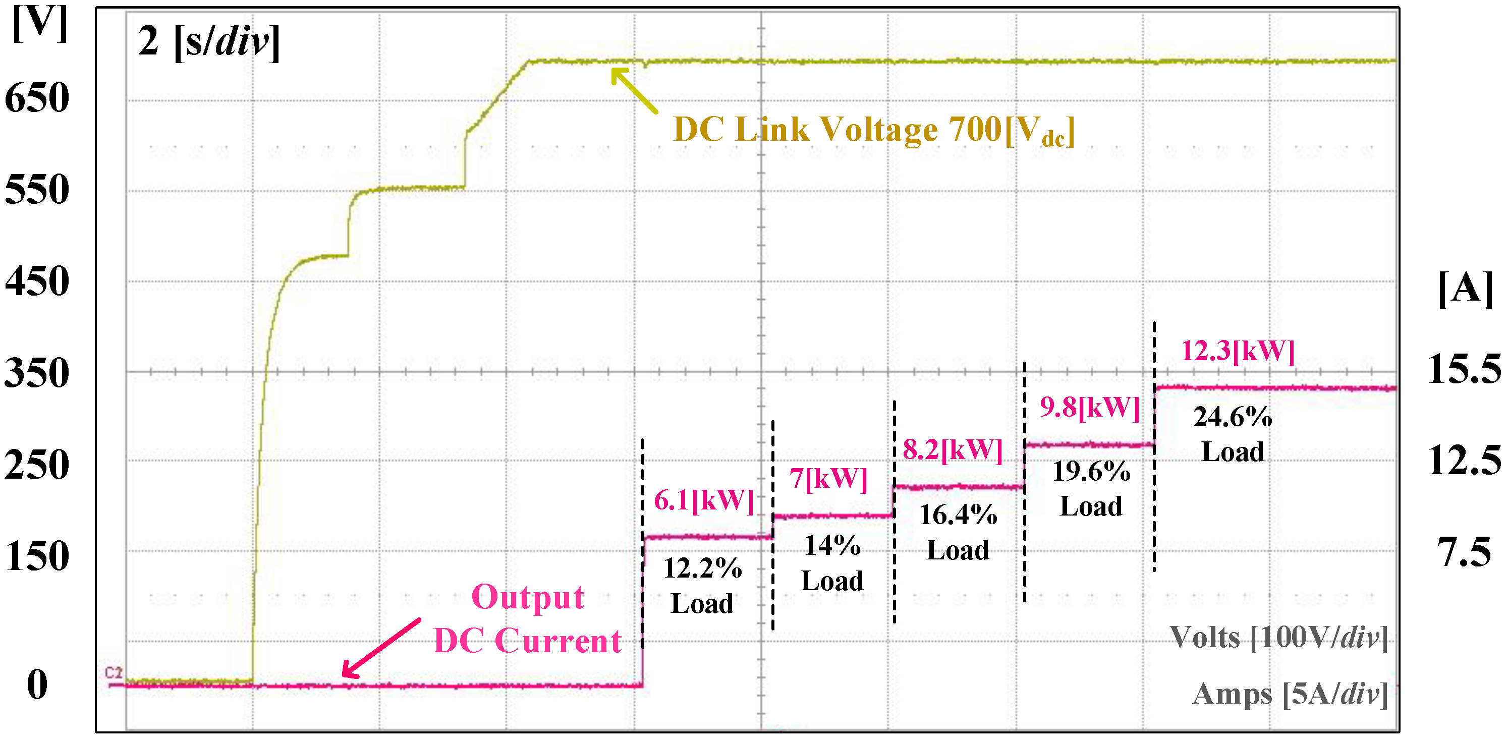
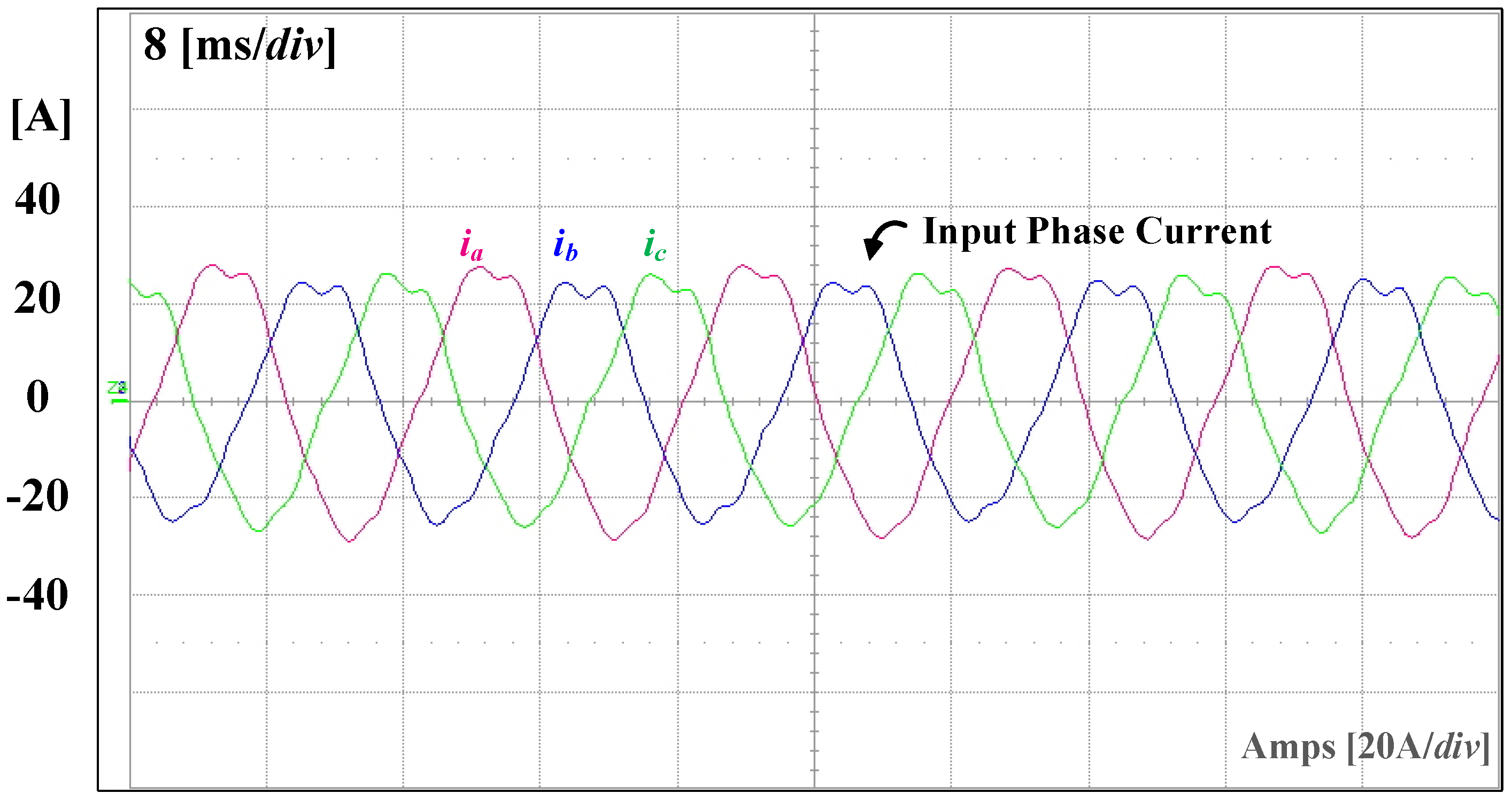
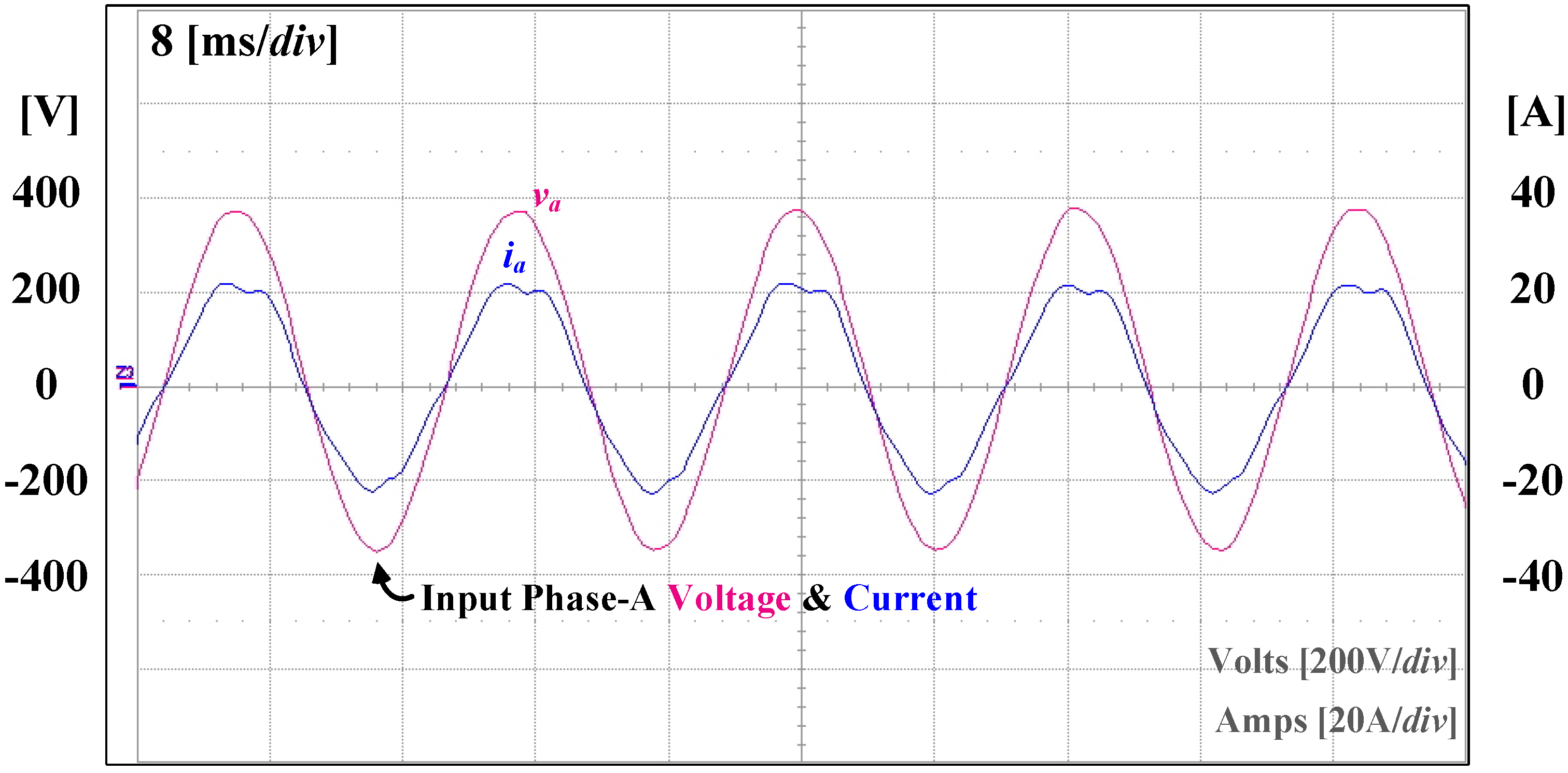
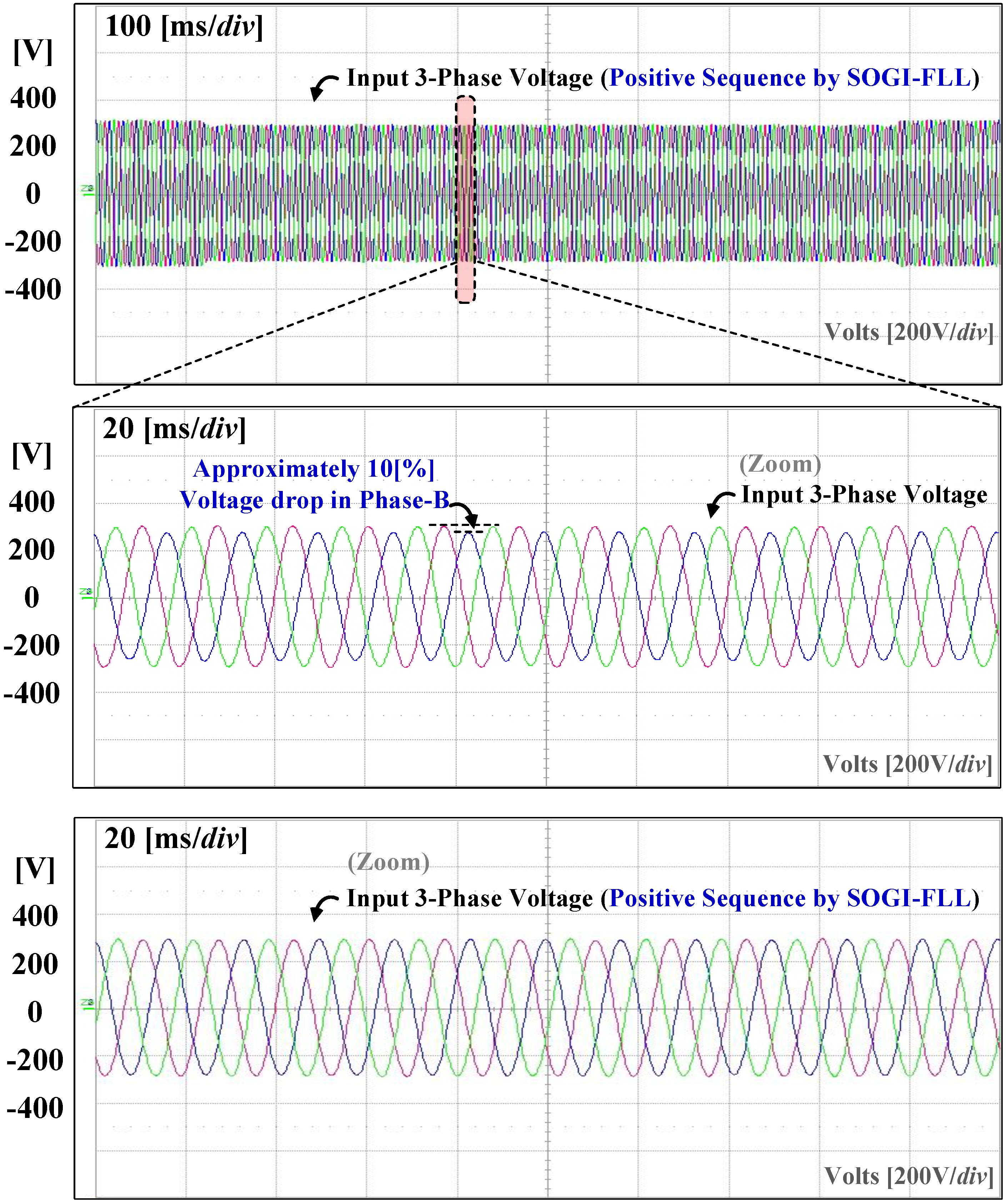
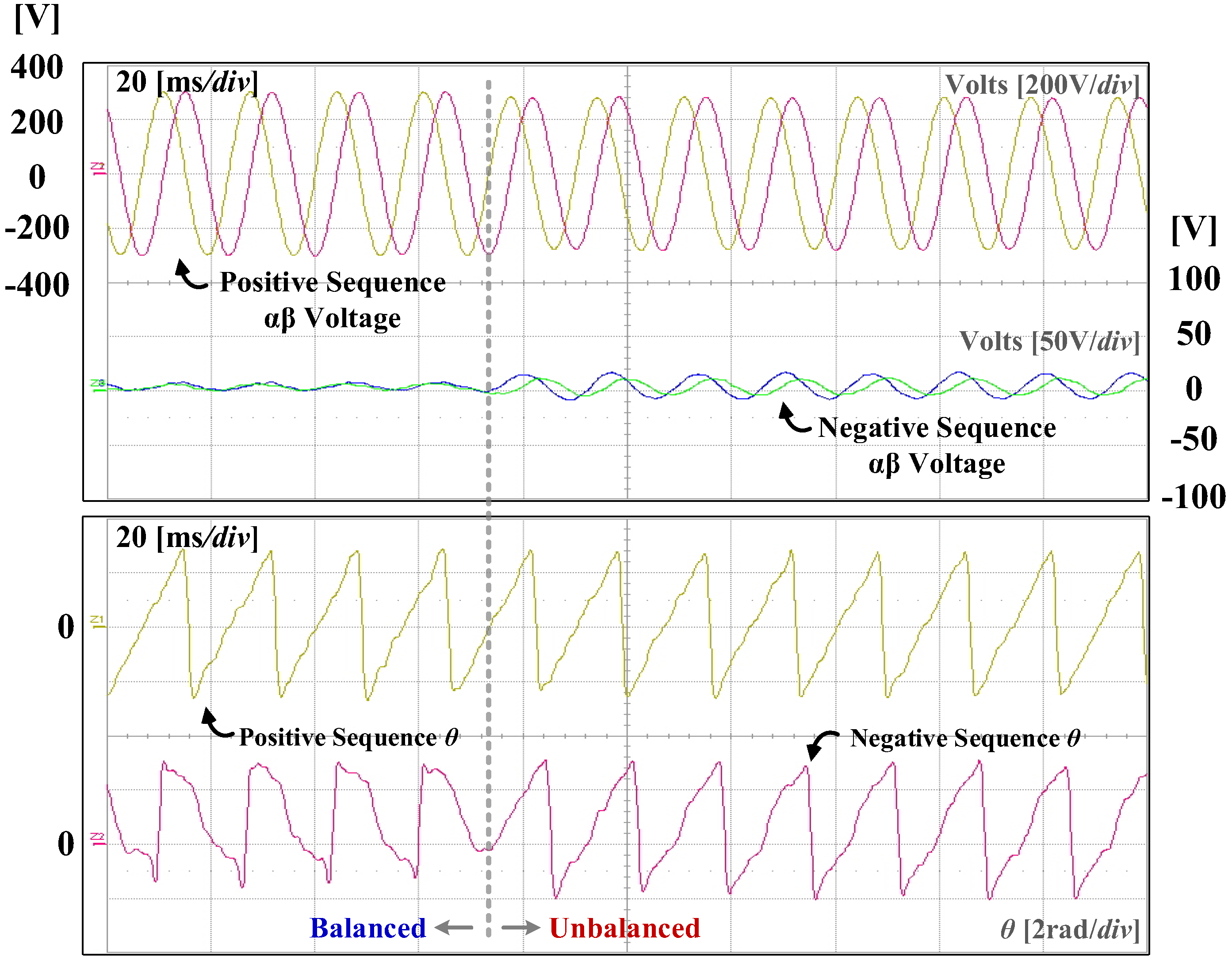
5. Experiment Results

An experiment was performed to verify the feasibility of the proposed control method that is applied in a 3-phase AC/DC PWM converter for a DC distribution system. The configurations of the experimental system and power stacks are shown in Figure 22, Figure 23 and Figure 24, and the experimental parameters are shown in Table 1.
Figure 25 shows the waveforms for the operating sequence of a 3-phase AC/DC PWM converter for DC distribution. To prevent an excessive inrush current to the capacitor, the dc-link capacitor is charged while using an initial charging circuit consisting of magnetic switch and a resistor. After the initial charging is completed, the main magnetic switch is activated and the voltage is charged to the capacitor up to the input phase voltage peak value of 311 Vdc. The controller then starts to operate and the voltage increases up to 700 Vdc, which is the voltage reference, and the operation maintains steady state. As the load capacity increases, the output current gradually increases and the voltage remains constant, despite the increasing load.
Figure 26 shows the input phase current waveform at the grid side when a load of 12.3 kW is applied, which is the largest capacity used of those shown in Figure 25. Since the load capacity is lower than that of the designed capacity of 50 kW, the current waveform includes the harmonics.
Figure 27 shows the grid side input a voltage and current waveforms. The phase angle of the input phase voltage was extracted while using the positive sequence voltage and phase detector using SOGI-FLL without the need to use the PLL of the conventional control or the PLL used for the coordinate transformation of the phase current. In addition, the power factor is controlled to be 1 by adjusting the d -axis current command in the synchronous reference frame, which is a reactive power component. The phase detection performance of SOGI-FLL is then verified by experiment waveform.
Figure 28 shows the 3-phase voltage waveform when a voltage drop (about 10%) occurs on the b phase. Figure 28b shows the expanded waveform of Figure 28a when the voltage drop occurs, and Figure 28c shows the waveform of the 3-phase positive sequence input voltage extracted while using SOGI-FLL. The amplitude of the 3-phase positive sequence voltage decreases due to the voltage drop. Even though the input 3-phase voltage is unbalanced, the extracted positive sequence voltage using SOGI-FLL maintains the balanced condition.
Figure 29 shows the positive and negative sequence α β voltage and phase angle θ , before and after the b phase voltage drop. In the case of the α β voltage in the stationary reference frame, the amplitude and phase angle of the positive sequence component are always the same as these of the grid side. While the appearance of the negative sequence component is negligible at the steady state, the amplitude varies depending on the distortion in the unbalance condition. The phase angle θ of the positive sequence is always rotated in the same direction. In the case of a negative sequence, the magnitude, direction, and shape of the phase angle change depending on the balance, unbalance, and distortion.

6. Conclusions

In this paper, we studied a control method using SOGI-FLL for a 3-phase AC/DC PWM converter that is used in a DC distribution system. The proposed control method comprises a SOGI-FLL, which performs positive sequence voltage extraction, phase angle extraction, and harmonic filtering without an additional filter.
In DC distribution system, the power delivered to the load will depend on the 3-phase AC/DC PWM converter that is connected to the grid. However, the conventional control method with PLL used in 3-phase AC/DC PWM converter can not flexibly cope with the various conditions occurred in the grid. Unlike the conventional method, the proposed control method using SOGI-FLL can allow for the stable power to supply to the load in DC distribution even when various conditions occurred in the grid because it have stable and fast transient characteristics.
Experiment and simulation applied to 50 kW 3-phase 2-level AC/DC PWM converter was performed to verify the feasibility and effectiveness of the proposed control method. As a result, stable and fast transient control was verified while using the proposed method, even if the input voltage includes various harmonics, the frequency changes and a voltage drop occurs. Given those results, it is expected that the proposed method based on SOGI-FLL is one of good candidates for DC distribution system.

Author Contributions

J.-W.K., and K.-W.S. conceived and designed the experiment; J.-W.K. and K.-W.S. performed the experiment; J.-W.K., K.-M.K., H.L. and K.-W.S. analyzed the theory. J.-W.K. and H.L. wrote the manuscript. J.K. and C.-Y.W. participated in research plan development and revised the manuscript. All authors have contributed to the manuscript.

Funding

This research received no external funding.

Acknowledgments

This work was supported by the Korea Institute of Energy Technology Evaluation and Planning (KETEP) and the Ministry of Trade, Industry & Energy (MOTIE) of the Republic of Korea. (No. 20162010103830). This work was supported by “Human Resources Program in Energy Technology” of the Korea Institute of Energy Technology Evaluation and Planning (KETEP), granted financial resource from the Ministry of Trade, Industry & Energy, Republic of Korea. (No. 20184030202190)

Conflicts of Interest

The authors declare no conflict of interest.

References

  1. Kim, H.S.; Ryu, M.H.; Baek, J.W.; Jung, J.H. High-Efficiency Isolated Bidirectional AC–DC Converter for a DC Distribution System. IEEE Trans. Power Electron. 2013, 28, 1642–1654. [Google Scholar] [CrossRef]
  2. Bosich, D.; Mastromauro, R.A.; Sulligoi, G. AC-DC interface converters for MW-scale MVDC distribution systems: A survey. In Proceedings of the 2017 IEEE Electric Ship Technologies Symposium (ESTS), Arlington, VA, USA, 15–17 August 2017; pp. 44–49. [Google Scholar]
  3. Rodríguez, P.; Teodorescu, R.; Candela, I.; Timbus, A.V.; Liserre, M.; Blaabjerg, F. New positive-sequence voltage detector for grid synchronization of power converters under faulty grid conditions. In Proceedings of the 37th IEEE Power Electronics Specialists Conference, Jeju, Korea, 18–22 June 2006; pp. 1–7. [Google Scholar]
  4. Bacon, V.D.; Oliveira da Silva, S.A. Performance improvement of a three-phase phase-locked-loop algorithm under utility voltage disturbances using non-autonomous adaptive filters. IET Power Electron. 2015, 8, 2237–2250. [Google Scholar] [CrossRef]
  5. Karimi-Ghartemani, M.; Iravani, M.R. A method for synchronization of power electronic converters in polluted and variable-frequency environments. IEEE Trans. Power Syst. 2004, 19, 1263–1270. [Google Scholar] [CrossRef]
  6. Jung, J.; Kim, H.; Ryu, M.; Kim, J.; Baek, J. Single-phase bidirectional AC-DC boost rectifier for DC distribution system. In Proceedings of the IEEE ECCE Asia Downunder, Melbourne, Australia, 3–6 June 2013; pp. 544–549. [Google Scholar]
  7. Jung, T.; Gwon, G.; Kim, C.; Han, J.; Oh, Y.; Noh, C. Voltage Regulation Method for Voltage Drop Compensation and Unbalance Reduction in Bipolar Low-Voltage DC Distribution System. IEEE Trans. Power Deliv. 2018, 33, 141–149. [Google Scholar] [CrossRef]
  8. Kim, H.; Ryu, M.; Baek, J.; Jung, J. High-Efficiency Isolated Bidirectional AC–DC Converter for a DC Distribution System. IEEE Trans. Power Electron. 2013, 28, 1642–1654. [Google Scholar] [CrossRef]
  9. Rodríguez, P.; Luna, A.; Muñoz-Aguilar, R.S.; Etxeberria-Otadui, I.; Teodorescu, R.; Blaabjerg, F. A Stationary Reference Frame Grid Synchronization System for Three-Phase Grid-Connected Power Converters under Adverse Grid Conditions. IEEE Trans. Power Electron. 2012, 27, 99–112. [Google Scholar] [CrossRef]
  10. Kang, J.; Hyun, S.; Hong, S.; Won, C. Advanced control method of 3-phase AC/DC PWM converter for DC distribution using the SOGI-FLL. In Proceedings of the IEEE 8th International Power Electronics and Motion Control Conference (IPEMC-ECCE Asia), Hefei, China, 22–26 May 2016; pp. 2120–2124. [Google Scholar]
  11. Kang, J.W.; Lee, H.; Hyun, S.W.; Kim, J.; Won, C.Y. An Enhanced Control Scheme Based on New Adaptive Filters for Cascaded NPC/H-Bridge System. Energies 2018, 11, 1034. [Google Scholar] [CrossRef]
  12. Jung, C.H. Control Method for Reducing Circulating Current in Parallel Operation of DC Distribution System for Building Applications. Master’s Thesis, Sungkyunkwan University, Suwon, Korea, February 2013. [Google Scholar]
  13. Han, D.W. Integrated Parallel Operation of Power Conversion Module for DC Distribution System. Master’s Thesis, Sungkyunkwan University, Suwon, Korea, February 2014. [Google Scholar]
  14. Park, Y.W. Parallel Control Using Current Droop Control of Cubic Equation for DC-grid Distribution Systems. Master’s Thesis, Sungkyunkwan University, Suwon, Korea, August 2014. [Google Scholar]
  15. Hadjidemetriou, L.; Kyriakides, E.; Blaabjerg, F. A New Hybrid PLL for Interconnecting Renewable Energy Systems to the Grid. IEEE Trans. Ind. Appl. 2013, 49, 2709–2719. [Google Scholar] [CrossRef]
  16. Rodriguez, P.; Luna, A.; Ciobotaru, M.; Teodorescu, R.; Blaabjerg, F. Advanced Grid Synchronization System for Power Converters under Unbalanced and Distorted Operating Conditions. In Proceedings of the IECON 2006-32nd Annual Conference on IEEE Industrial Electronics, Paris, France, 6–10 November 2006; pp. 5173–5178. [Google Scholar]
  17. Mnider, A.M.; Atkinson, D.J.; Dahidah, M.; Zbede, Y.B.; Armstrong, M. A programmable cascaded LPF based PLL scheme for single-phase grid-connected inverters. In Proceedings of the 7th International Renewable Energy Congress (IREC), Hammamet, Tunisia, 22–24 March 2016; pp. 1–6. [Google Scholar]
  18. Yuan, X.M.; Merk, W.; Stemmler, H.; Allmeling, J. Stationary-frame generalized integrators for current control of active power filters with zero steady-state error for current harmonics of concern under unbalanced and distorted operating conditions. IEEE Trans. Ind. Appl. 2002, 38, 523–532. [Google Scholar] [CrossRef] [Green Version]
  19. Rodriguez, P.; Luna, A.; Candela, I.; Teodorescu, R.; Blaabjerg, F. Grid synchronization of power converters using multiple second order generalized integrators. In Proceedings of the 34th Annual Conference of IEEE Industrial Electronics, Orlando, FL, USA, 10–13 November 2008; pp. 755–760. [Google Scholar]
  20. Rodriguez, P.; Luna, A.; Etxeberria, I.; Hermoso, J.R.; Teodorescu, R. Multiple. Second order generalized integrators for harmonic synchronization of power converters. In Proceedings of the IEEE Energy Conversion Congress and Exposition, San Jose, CA, USA, 20–24 September 2009; pp. 2239–2246. [Google Scholar]
  21. Xin, Z.; Qin, Z.; Lu, M.; Loh, P.C.; Blaabjerg, F. A new second-order generalized integrator based quadrature signal generator with enhanced performance. In Proceedings of the IEEE Energy Conversion Congress and Exposition (ECCE), Milwaukee, WI, USA, 18–22 September 2016; pp. 1–7. [Google Scholar]
  22. Ciobotaru, M.; Teodorescu, R.; Blaabjergc, F. A new single-phase PLL structure based on second order generalized integrator. In Proceedings of the 37th IEEE Power Electronics Specialists Conference, Jeju, Korea, 18–22 June 2006; pp. 1–6. [Google Scholar]
  23. Rocha, C.X.; Camacho, J.R.; Viajante, G.P. Fault detection in a three-phase system grid connected using SOGI structure to calculate vector components. In Proceedings of the International Conference on Renewable Energies and Power Quality (2015 ICREPQ), La Coruña, Spain, 25–27 March 2015; pp. 25–27. [Google Scholar]
  24. Nam, K.Y.; Choi, S.B.; Ryoo, H.S.; Jeong, S.H.; Lee, J.D.; Jung, D.H.; Kim, D.K. Establishment of Test Field for Application of IEC 60364-4-44 in Korea. In Proceedings of the IEEE PES Power Systems Conference and Exposition, Atlanta, GA, USA, 29 October–1 November 2006; pp. 1944–1949. [Google Scholar]
  25. Golestan, S.; Guerrero, J.M. Conventional Synchronous Reference Frame Phase-Locked Loop is an Adaptive Complex Filter. IEEE Trans. Ind. Electron. 2015, 62, 1679–1682. [Google Scholar] [CrossRef] [Green Version]
Figure 1. Configuration of 3-phase alternating current/direct current (AC/DC) pulse width modulation (PWM) converter.
Applsci 08 01387 g001
Figure 2. Equivalent circuit of 3-phase AC/DC PWM converter.
Applsci 08 01387 g002
Figure 3. Equivalent circuit of a 3-phase AC/DC PWM converter.
Applsci 08 01387 g003
Figure 4. Phasor diagram of a 3-phase AC/DC PWM converter.
Applsci 08 01387 g004
Figure 5. Control block diagram of positive sequence voltage and phase detector.
Applsci 08 01387 g005
Figure 6. Control block diagram of phase detector using first order low pass filter and proportional integral (PI) controller.
Applsci 08 01387 g006
Figure 7. Control block diagram of second order generalized integrator (SOGI)-based adaptive filter (AF) (= SOGI-quadrature signal generator (QSG)).
Applsci 08 01387 g007
Figure 8. Comparison of transfer function D ( s ) and Q ( s ) .
Applsci 08 01387 g008
Figure 9. Characteristics of SOGI-based AF various gain k .
Applsci 08 01387 g009
Figure 10. Control block diagram of SOGI-frequency locked loop (FLL) for phase synchronization.
Applsci 08 01387 g010
Figure 11. Comparison of transfer functions E ( s ) and Q ( s ) .
Applsci 08 01387 g011
Figure 12. 3-phase SOGI-FLL (= DSOGI-FLL).
Applsci 08 01387 g012
Figure 13. Positive sequence voltage extractor using 3-phase SOGI-FLL.
Applsci 08 01387 g013
Figure 14. Control block diagram of 3-phase AC/DC PWM converter with SOGI-FLL.
Applsci 08 01387 g014
Figure 15. 3-phase AD/DC PWM converter schematic of DC distribution system used in simulation.
Applsci 08 01387 g015
Figure 16. Input and output waveforms of DC distribution system (a) the dc-link voltage; (b) the current of the DC load; and, (c) the current of the grid.
Applsci 08 01387 g016
Figure 17. Waveform of voltage when harmonics is included in input side; (a) the 3-phase input voltage with harmonic components; and, (b) the 3-phase input voltage detected by the SOGI-FLL.
Applsci 08 01387 g017
Figure 18. Waveforms of simulation results when b phase has a voltage drop; (a) the dc-link voltage; (b) the 3-phase input voltage with voltage unbalance; (c) the 3-phase input positive voltage detected by SOGI-FLL; (d) the 3-phase input current; and, (e) the center frequency extracted from SOGI-FLL.
Applsci 08 01387 g018aApplsci 08 01387 g018b
Figure 19. Waveforms of simulation results when voltage drop is occurred; (a) the positive and negative sequence voltage; and, (b) the phase angle of the positive and negative sequence voltage.
Applsci 08 01387 g019
Figure 20. Waveforms of simulation results when grid frequency decreased from 60 Hz to 45 Hz drop; (a) the dc-link voltage; (b) the 3-phase input voltage; (c) the 3-phase input positive voltage detected by SOGI-FLL; (d) the 3-phase input current; and, (e) the center frequency that was extracted from SOGI-FLL.
Applsci 08 01387 g020aApplsci 08 01387 g020b
Figure 21. Waveforms of simulation results when frequency suddenly change (a) the DC-link voltage, d and q-axis voltage in synchronous reference frame with conventional synchronous reference frame-phase locked loop (SRF-PLL) (b) the DC-link voltage, d and q-axis voltage in synchronous reference frame with proposed control method.
Applsci 08 01387 g021
Figure 22. Configuration of the experiment system. MC: Magnetic Contactor.
Applsci 08 01387 g022
Figure 23. Experiment setup 1 of the 3-phase AC/DC PWM converter.
Applsci 08 01387 g023
Figure 24. Experiment setup 2 of the 3-phase AC/DC PWM converter. SMPS: switched-mode power supply; DSP: digital signal processor; MCCB: molded case circuit breaker.
Applsci 08 01387 g024
Figure 25. Waveform of 3-phase AC/DC PWM converter operation.
Applsci 08 01387 g025
Figure 26. Waveform of input phase current of 3-phase AC/DC PWM converter.
Applsci 08 01387 g026
Figure 27. Waveform of input phase a voltage and current.
Applsci 08 01387 g027
Figure 28. Waveforms of extracted 3-phase positive sequence input voltage using SOGI-FLL when the b phase has voltage drop.
Applsci 08 01387 g028
Figure 29. Waveform of detected positive/negative sequence α β voltage and phase angle θ (before and after b phase voltage drop).
Applsci 08 01387 g029
Table 1. Simulation parameter of DC distributed system.
ParameterValueUnit
Rated power of system50[kW]
3 phase line-to-line grid voltage380[Vrms]
Grid frequency60[Hz]
Switching frequency5[kHz]
Output DC-link voltage 700[Vdc]
DC-link capacitance10200[ μ F ]
LCL filter inductance at grid side 120[ μ H ]
LCL filter capacitance50[ μ F ]
LCL filter inductance at converter side500[ μ H ]

