Article

A Solar–Thermal-Assisted Adiabatic Compressed Air Energy Storage System and Its Efficiency Analysis

1
China State Key Laboratory of Power System and Generation Equipment, Department of Electrical Engineering, Tsinghua University, Beijing 100084, China
2
School of QiDi (TUS) Renewable Energy, Qinghai University, Xining, Qinghai 810036, China
3
Hebei Electric Power Design & Research Institute, Shijiazhuang 221116, China
*
Author to whom correspondence should be addressed.
Submission received: 14 June 2018 / Revised: 10 August 2018 / Accepted: 14 August 2018 / Published: 17 August 2018
(This article belongs to the Special Issue Smart Grid and Smart Cities Activities)

Abstract

:
Adiabatic compressed air energy storage (A-CAES) is an effective balancing technique for the integration of renewables and peak-shaving due to the large capacity, high efficiency, and low carbon use. Increasing the inlet air temperature of turbine and reducing the compressor power consumption are essential to improving the efficiency of A-CAES. This paper proposes a novel solar–thermal-assisted A-CAES system (ST-CAES), which features a higher inhale temperature of the turbine to improve the system efficiency. Solar–thermal energy, as an external thermal source, can alleviate the inadequate temperature of the thermal energy storage (TES), which is constrained by the temperature of the exhaust air of the compressor. Energy and exergy analyses were performed to identify ST-CAES performance, and the influence of key parameters on efficiency were studied. Furthermore, exergy efficiency and the destruction ratio of each component of ST-CAES were investigated. The results demonstrate that electricity storage efficiency, round-trip efficiency, and exergy efficiency can reach 70.2%, 61%, and 50%, respectively. Therefore, the proposed system has promising prospects in cities with abundant solar resources owing to its high efficiency and the ability to jointly supply multiple energy needs.

1. Introduction

Modern cities are facing environmental and energy shortage issues, and the large-scale development and utilization of renewable energy sources (RES) in smart cities is a primary strategy for addressing those issues [1]. However, much wind and solar energy is curtailed due to a lack of reasonable planning and compatibility with conventional energy [2,3,4]. Notably, in 2017, the average curtailment ratios of wind and solar power in Gansu Province, China reached 25% and 20%, respectively [5]. Moreover, RES will enlarge the peak to valley difference of power demands. These facts have posed great challenges to the smart grid and caused crises in secure operation [6]. Therefore, strategies to ensure the large-scale utilization of RES in a safe, efficient, and economical way has become a crucial issue in the construction of today’s smart grid and city.
Energy storage has been recognized as an effective means of RES integration and peak-shaving [7]. Currently, compressed air energy storage (CAES) and pumped storage systems (PHS) are the major large-scale energy storage technologies [8,9]. Compared with PHS, CAES has broad application prospects because the geographic conditions or water resources hardly constrain it. Nevertheless, commercial CAES plants, including Huntorf (E.N Kraftwerke, Huntorf, Germany, 1978) and McIntosh (Alabama, America, 1991), strongly depend on natural gas to enhance electricity storage efficiency [10,11], which is a restriction in areas without abundant natural gas resources.
Integrated with thermal energy storage (TES), adiabatic CAES (A-CAES) is the main trend of CAES that is independent of fossil fuels. Several A-CAES projects have been announced, are under construction, or are in operation [12]. Germany has planned to build a large-scale A-CAES power plant with a target cycle power of 70% [13]. China’s first 500 kW A-CAES demonstration system successfully realized energy storage and power generation in 2014 [14,15]. In addition, a national A-CAES demonstration power station led by Tsinghua University, with rated power of 60 MW and rated capacity of 300 MWh, is under construction in China [16].
However, constrained by the efficiency and structure of compressors and the effectiveness of multi-stage heat exchangers, the heat medium of TES that depend on compression heat cannot reach a high temperature [17]. Consequently, it is difficult to enlarge electricity production in the discharge process, which may not balance the load demand and confine system efficiency. It is an effective measure to replace the TES of A-CAES with solar thermal collection and storage (STC) of concentrating solar power to overcome deficient heat capacity. Hybrid A-CAES (HA-CAES) notably enhances the storage heat temperature and capacity and can also improve the comprehensive utilization level of clean energy [18,19]. Therefore, researchers have recently begun to focus on essential technologies of HA-CAES such as process design, efficiency analysis, and key parameter optimization to improve the system efficiency.
A gas turbine combined solar energy and CAES focusing on process design and efficiency analysis has been proposed, and characteristics of its off-design were studied in [20]. To cope with the issue of wind and solar curtailment, a novel scheme of wind-energy complementary A-CAES was presented and its thermodynamic characteristics were analyzed in [21]. A HA-CAES design scheme to optimize cycle efficiency and efficiency for microturbines, solar dish collectors, and A-CAES was described in [22,23]. Modeling and analysis of combined cooling heating and power (CCHP) integrated solar thermal energy for its cogeneration characteristics were established in [24]. Because of the multi-carrier poly-generation capability, an HA-CAES-based multi-carrier clean energy hub is proposed and modeled in [25] to realize the comprehensive consumption of the renewable energy. A HA-CAES is utilized as an energy hub in a solar-based smart micro-energy grid in [26].
However, few studies have worked on enhancing the comprehensive efficiency with stable solar thermal resources and utilizing compression heat to supply heat to residents. Unstable thermal resources cause low system electrical storage, round-trip and exergy efficiencies.
In this paper, a novel solar–thermal-assisted A-CAES (ST-CAES) is proposed to attain high efficiency. During the charging process, low-price electricity such as curtailed wind, solar, and off-peak electricity, is used to compress ambient air to high-pressure air and store it in a steel pipeline tank (SPT), recovering compression heat that could be used for heating. Solar–thermal energy is collected and stored by STC, which can supply stable thermal energy. During the discharging process, the stored high-pressure air is released and preheated with the exhaust air of a turbine, and further heated with the stored stable solar–thermal energy to generate electricity. The use of solar thermal energy improves the intake air temperature of the turbine generator, thereby enhancing the efficiency of ST-CAES. In consequence, ST-CAES can provide benefits to the smart grid and integrated RES.
The major contributions of this paper are: (1) A novel hybrid A-CAES based on the utilization of solar energy, which can be used for RES integration and peak-shaving and, furthermore, could significantly improve the round-trip efficiency, is proposed and analyzed; (2) Compared to the current HA-CAES, ST-CAES eliminates the combustion chamber that has already been proposed in [22]. Consequently, it is a zero-carbon-emission system. Moreover, ST-CAES can provide stable high-grade thermal energy in the discharging process, which is compared with HA-CAES in [23], and can greatly simplify the regenerative system.
The rest of this paper is organized as follows. Section 2 elaborates the overall design scheme and mathematic model of ST-CAES. Section 3 presents an energy and exergy analyses of ST-CAES. This is associated with the influence of primary parameters on system performance in Section 4, followed by the conclusions in Section 5.

2. System Description

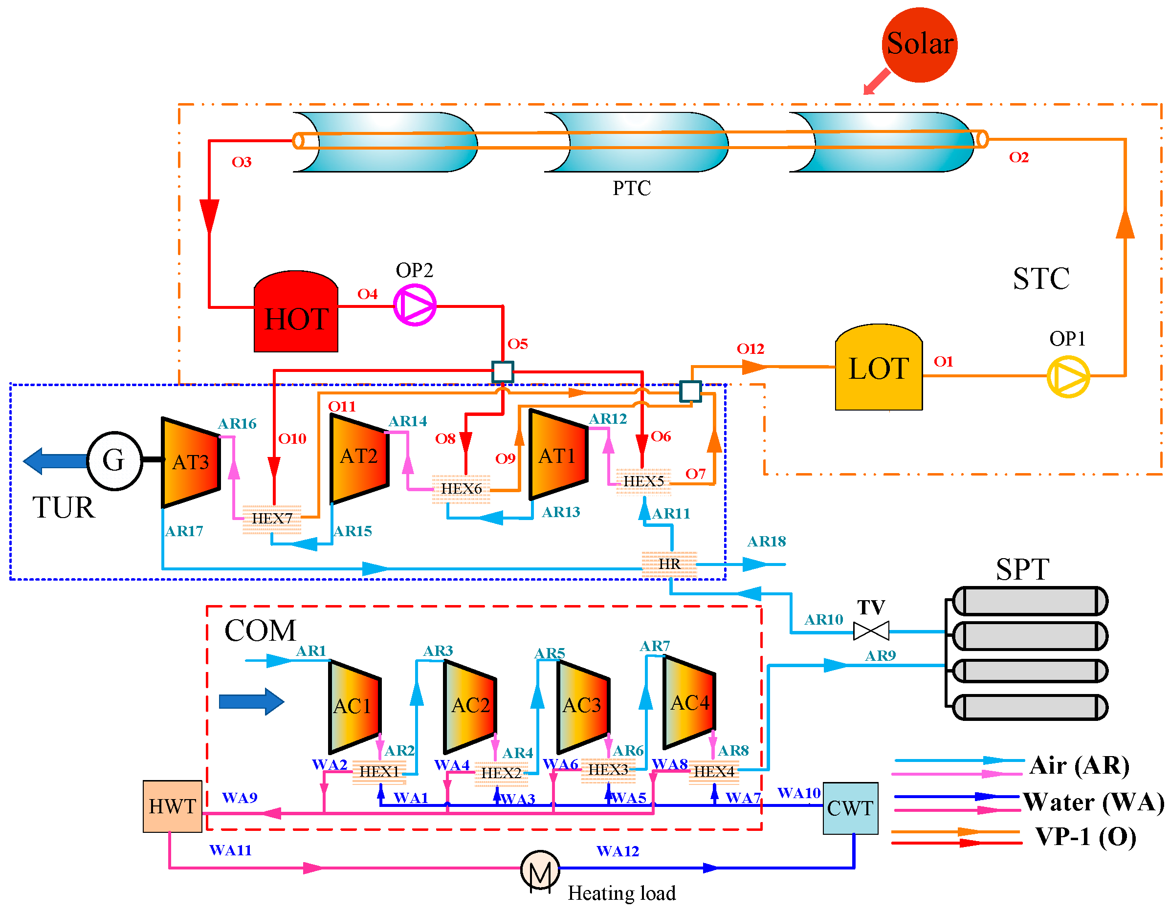
The implementation of an ST-CAES with four-stage compression and three-stage expansion is illustrated in Figure 1. The system comprises three main subsystems, including a compression subsystem (COM), a solar thermal collection and storage (STC), and a turbine subsystem (TUR). The COM contains a four-stage compressor train (AC1-AC4), four-stage heat exchangers (HEX1-HEX4), a cold-water tank (CWT), and a hot water tank (HWT). It is worth noting that the number of compression stages is determined by the maximum pressure of the steel pipeline tank (SPT) and the type of compressor in use. The designed maximum pressure of (SPT) is 10 MPa and the conventional single-stage pressure ratio of the reciprocating piston compressor is approximately 3. Therefore, the four-stage compressor can meet the requirement of maximum air pressure in SPT.
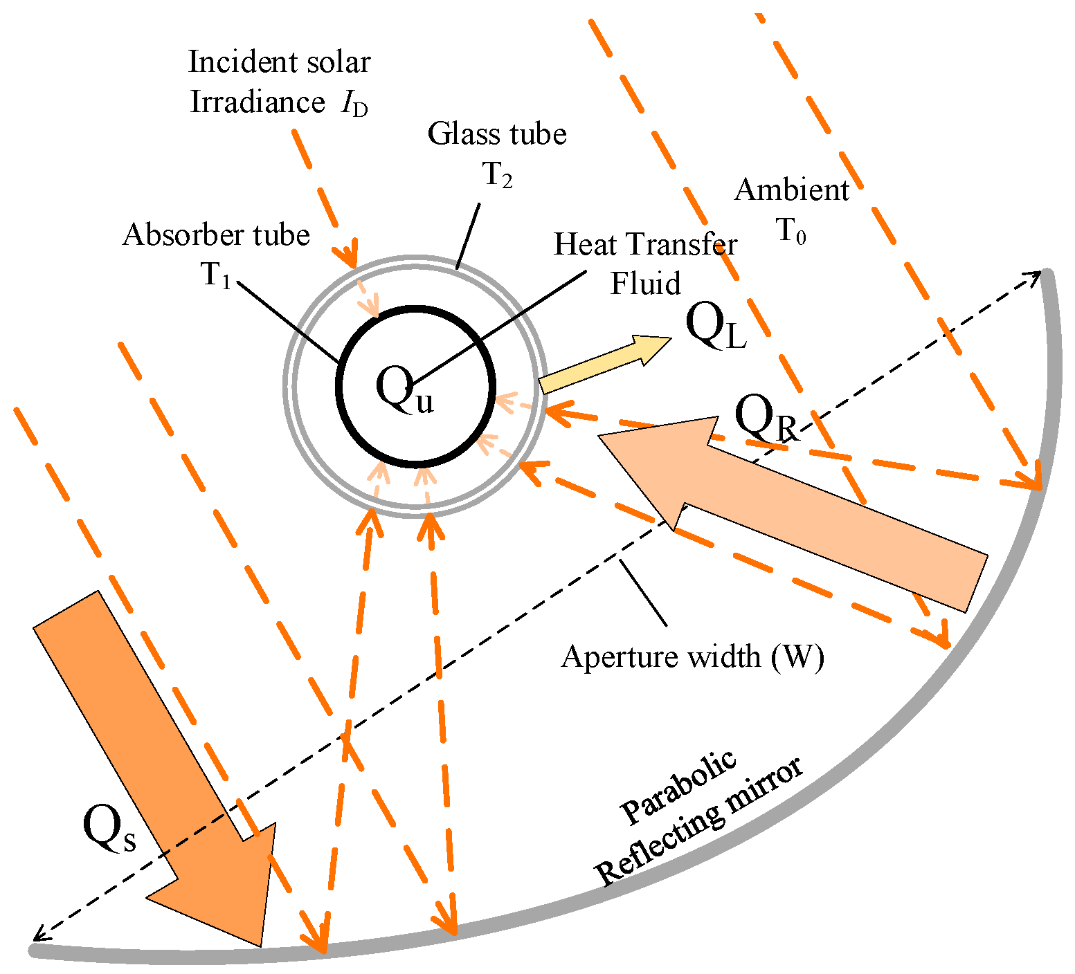
The STC consists of a parabolic trough collector (PTC), a low-temperature oil tank (LOT), and a high-temperature oil tank (HOT). The TUR includes a throttle valve (TV), an air turbine chain (AT1-AT3), a heat regenerator (HR), and three heat exchangers (HEX5-HEX7) as well. Moreover, three types of fluids are introduced into the system, namely air (AR), water (WA), and Therminol oil VP-1 (O). To clearly describe the system, all the components and streams are listed and numbered as in Figure 1.
Although the COM and TUR subsystems are similar to the A-CAES reported in numerous studies [12,13,14,15], ST-CAES features several distinct characteristics. Firstly, the compression heat is absorbed and stored in HWT and utilized to provide thermal energy to residents. Secondly, low-temperature thermal oil from LOT is heated by the PTC to attain high temperatures and then stored in an HOT that can supply stable heat resources. Thirdly, the compressed air is preheated by exhaust air before entering the air turbine, and further heated by the high-temperature oil from the HOT through heat exchangers (HEX5-HEX7) to improve the system efficiency.

3. Thermodynamic Analysis Model

3.1. Basic Assumptions and Mathematical Model

The proposed ST-CAES system is comprised of a conventional CAES and a STC subsystem. The classical Peng–Robinson equations of the state were selected as the property package. The analysis was carried out using Thermoflow software. To simplify the analysis, the following assumptions are made:
  • The system operates in a steady state condition;
  • All gases in the system are treated as the ideal gas;
  • A constant isentropic efficiency is assumed for the compressors and air turbine;
  • The pressure drop of each heat exchanger is 2%, and its heat loss is ignored.

3.2. Energy Analysis Model

3.2.1. Conventional CAES

The energy analysis of the ST-CAES system is based on the first law of thermodynamics. It describes the process of energy transfer and conversion of each component. Outlet temperature T o u t c , i of the compressor is obtained via:
T o u t c , i = T i n c , i ( 1 + 1 η c o m ( β i k 1 k 1 ) ) ,
where k is the polytropic index, β is the pressure ratio, and η c o m represents the adiabatic efficiency of the compressor, which is calculated by
η c o m = h o u t , s h i n h o u t h i n .
The required power of the compressor is equal to the enthalpy difference between the outlet and inlet streams multiplied by its mass flow rate, and is obtained by
W c o m = i = 1 4 m A R i n ( h o u t i h i n i ) ,
where Wcom is the compressor power consumption and mARin is the mass flow rate of the compressor.
Energy balance allows for computation of the amount of hot water power produced in HEX1-HEX4:
Q h e a t = m A R ( h A R , i n h A R , o u t ) = m W A ( h W A , o u t h W A , i n ) ,
where Qheat is the recovery compression heat power that can supply heat to residents.
The charge and discharge time of the SPT are decided by the maximum and minimum allowable air pressures:
τ c h = ( p max p 0 ) V S P T m A R 9 R T ,
τ d c h = ( p max p 0 ) V S P T m A R 10 R T ,
where τch and τdch are the charge and discharge time, respectively; VSPT is the volume of SPT; R is the gas constant of air under normal circumstances; and T is the temperature in SPT.
To calculate the outlet temperature of the air turbine, T o u t e , j (streams AR13, AR15, and AR17), the following is used:
T o u t e , j = T i n e , i ( 1 η e ( 1 π j 1 k k ) ) ,
where π is the expand ratio, and the isentropic efficiency of the turbine ηe is defined by
η e = h o u t h i n h o u t , s h i n .
An STC subsystem is used to collect and store solar radiation energy to heat the inlet air of the turbine. The temperature of the heated air is obtained from the energy balance as shown by
m A R 10 ( h A R i n h A R o u t ) = m O ( h O o u t h O i n ) .
The output power of the air turbine generator WTur is
W T u r = j = 1 3 m A R 10 ( h o u t j h i n j ) .

3.2.2. STC

The STC system includes PTC and a heat storage tank. The PTC thermal model is shown in Figure 2. Its collecting thermal efficiency, ηc, is defined as the ratio of useful energy Qu absorbed by the HTF to energy incident on the parabolic reflecting mirror, which is outlined as follows [27]:
η C = Q u Q s ,
where the incident energy, Qs, is proportional to the PTC area and direct normal insolation per unit of collector area, and is computed by
Q s = I D A ,
where ID is the direct normal irradiation and A is the effective collection area. A part of the solar energy is delivered to the receiver, and the amount of that energy is a function of the parabolic trough mirror optical efficiency. Equation (13) shows the relationship between the optical efficiency and the incident energy. We assumed a constant value of 0.9 for the optical efficiency of the collector. The reflecting heat power QR by parabolic reflecting mirror is
Q R = η o p Q s ,
where ηOP is the optical efficiency. The useful heat energy Qu obtained by the absorber tubes is computed by
Q u = Q R Q L .
To obtain the useful heat absorbed by the receiver, its heat loss should be calculated. In general, there are three types of heat dissipation, namely conduction, convection, and radiation. Therefore, the total heat loss QL of the receiver can be expressed as [28]:
Q L = Q c o n d + Q c o n v + Q r a d .
To simplify the analysis, the thicknesses of the glass envelope and absorber tube are not considered, and the heat conduction loss between the absorber tube and the glass tube is ignored. The heat convection loss, based on Newton’s law, is as follows:
Q c o n v = Q c o n v 1 , 2 + Q c o n v 2 , 0 , Q c o n v 1 , 2 = h d ( T 1 T 2 ) A a b , Q c o n v 2 , 0 = h c ( T 2 T 0 ) A g ,
where Qconv1,2 is the heat convection loss between the absorber tube surface and inner glass tube. Qconv2,0 is the heat convection loss between the inner glass tube and the external environment. Aab and Ag are the surface areas of the absorber and glass tube, respectively. hd is the convection heat transfer coefficient of the annular space. hc is the convection heat transfer coefficient of the glass tube and environment, and T1 and T2 are the surface temperatures of the absorption tubes and glass tubes, respectively.
Q r a d = Q r a d 1 , 2 + Q r a d 2 , 0 .
The operation characteristics of the absorber tube show that the temperature of absorber tube is much higher than that of the glass tube. The heat radiation between them is calculated by
Q r a d 1 , 2 = σ ( T 1 4 T 2 4 ) 1 / ε 1 + ( 1 ε 2 ) D 1 / ε 2 D 2 A a b ,
where σ is the Stefan–Boltzmann constant (W/m2-K4) and D1 and D2 are the outer absorbers and inner glass tube diameters, respectively. T1 is the outer absorber surface temperature, and T2 is the inner glass tube surface temperature. ε1 is the absorber selective coating emissivity, and ε2 is the glass tube emissivity. The heat radiation between the glass absorber and the environment is calculated via
Q r a d 2 , 0 = σ ε 2 ( T 2 4 T 0 4 ) A g .
The thermal energy tanks are modeled by dynamic mass and energy balances for two tanks [29]. The mass balance for a tank is
ρ H T F d V H T F d t = m i n m o u t ,
where VHTF is the volume of HTF in the tank, and ρHTF refers to the density of HTF.
The energy balance for each tank is
ρ H T F C H T F d ( V H T F T ) d t = C H T F ( T i n m i n T m o u t ) U A t ( T T 0 ) ,
where U is the overall heat transfer coefficient for the tank walls and At is the surface area of the tank subject to the heat transfer. It is assumed that no heat transfer occurs from the top or bottom of either tank because the volumes of HTF (VHTF) in the tanks are not constant. The energy balances are solved for the product VHTFT. For further clarity, the key design factors of the parabolic trough collectors (PTC) are enumerated. The key design factors and thermal characteristics that impact the efficiency of PTC are shown in Table 1.
The major design factors are the mirror field area and optical efficiency [30]. Under certain solar irradiation conditions, the collected heat energy increases with enlargement in the mirror field area. The optical efficiency is affected by the glass envelop transmissivity, optical intercept factor, and cosine loss correction factor, which relies on tracking accuracy. As the optical efficiency increases, the collecting thermal efficiency also increases.

3.3. Exergy Analysis Model

An exergy analysis based on the second law of thermodynamics can be performed to decide the exergy destruction of each subsystem. Generally, the enthalpy exergy of state i can be calculated by
E x i = m i [ ( h i h 0 ) T 0 ( s i s 0 ) ] ,
where mi is the mass flow rate, h is the specific enthalpy, s is the specific entropy, and subscripts i and 0 represent state i and ambient conditions, respectively.
The thermal exergy supplied for TUR by the STC can be calculated via
E x H T F = E x O 5 E x O 12 .
The thermal exergy supplied by the compression heat can be calculated via
E x h e a t = E x W A 11 E x W A 12 .

3.4. Performance Criteria

The proposed ST-CAES system has two operational modes: energy storage and energy release. Different from conventional CAES, the energy storage mode can be divided into air storage and solar thermal collection and storage processes. It is worth mentioning that the solar thermal collection and storage process is independent of air compression. Therefore, these two processes can be conducted simultaneously. In the energy release mode, the stored high-pressured air in SPT and thermal energy in HOT are released simultaneously and drive the air turbine to generate electric energy. The electricity storage efficiency (ESE), round-trip efficiency (RTE), and exergy efficiency are important indices to analyze the performance of the proposed system. The ESE is defined as the electricity generation in the discharging process divided by power consumption in the charging process. The power consumption of the water and oil pumps is neglected because of their low values. Therefore, the ESE can be expressed as
η E S E = W T U R τ d c h W C O M τ c h .
RTE is defined as the ratio of total thermal and electrical energy output to total solar and electrical energy input in a full charge/discharge cycle. It can be expressed as
η R T E = W T U R τ d c h + Q h e a t τ h s W C O M τ c h + Q u τ c .
The exergy efficiency can be represented as
η E X E = W T U R τ d c h + E x h e a t τ h s W C O M τ c h + E x H T F τ c ,
where Qheat is the thermal energy supply to the heat load, Qu is collected and stored solar thermal energy, Exheat is enthalpy exergy of Qheat, and ExHTF is the HTF enthalpy exergy absorbed by the PTC.
For each subsystem j, the exergy destruction and exergy efficiency can be calculated as follows:
L j = E j , i n E j , o u t ,
η EXE , j = E j , o u t E j , i n ,
where the subscripts in and out represent the input and output states, respectively, of subsystem j. The expressions for input and output exergy of each subsystem are listed in Table 2.

4. Results and Discussion

4.1. Typical Operational Conditions

In this section, the performance of ST-CAES under typical operational conditions is analyzed. Table 3 lists the design parameters of the system. In this case, the durations of charging and discharging were the same (4 h), and the mass flow rate of the air was fixed at 0.56 kg/s. The adiabatic efficiency of the air compressors was 86%. The pressure of the outlet air of the throating valve (state A10), which is defined as the minimum SPT pressure, is approximately equal to the pressure of the inlet air of the first-stage air turbine (state A11). From the calculation presented in this section, the compression and expansion pressures were selected as 10 and 7 MPa, respectively. The effects of the compression and expansion pressures on system performance are discussed in Section 4.2. In the TUR subsystem, the adiabatic efficiency of the turbines was selected at 85%. The other parameters of the STC were selected by previous studies [31,32].
Table 4 lists the main simulation results of the ST-CAES system under typical operational conditions. Table 4 and Table 5 list the stream parameters of air and other fluids, respectively. As shown in Table 3, the total compression power consumption was 329.9 kW, and the heat energy collected from solar was 213.5 kW. The output power of the turbine was 231.5 kW. The mass flow rate associated with the consumption of cooling water was 1.36 kg/s, and the consumed solar thermal power to heat the inlet air of the turbine was 189.67 kW. The ESE, RTE, and exergy efficiency of the proposed system were 70.2%, 61%, and 50%, respectively. As listed in Table 4, the temperatures of supply and return water for the heating load were 80 and 30 °C. Under average solar irradiation operational conditions, the system needed about 6 h to raise 11.7 tons of VP-1 from 115 to 305 °C. Output power of the turbine is strongly influenced by the VP-1 temperature provided by collected and stored solar energy, which is discussed in Section 4.2. A-CAES performance depends on the key technology of A-CAES, which is to recover and store compression heat in thermal energy storage (TES) [33]. This is greatly constrained by structure of compressor and multi-stage heat exchanger effectiveness. The use of solar thermal energy can eliminate the high-temperature limit of the compressor and complex heat regeneration subsystem, which can greatly simplify the structure of A-CAES [14]. For a 4-h discharge duration with total power generation capacity of 955.4 kWh, Table 5 and Table 6 list the stream thermodynamic parameters of air, water, and Therminol VP-1.
To assess the performance of each subsystem, the exergy efficiency, and destruction were calculated from Equations (26) and (27) and Table 2. Figure 3 shows the exergy efficiency of each subsystem. The exergy efficiencies of the STC subsystem were much lower than those of the other subsystems except HEX of TUR, because of the basic STC characteristics. In the STC, absorption energy of the heat medium is supplied by stored Therminol VP-1 in the HOT hot oil tank, and this is greatly affected by the area of mirrors field, mass flow, weather, optical efficiency, and tracking accuracy of PTC [32]. Further, the HEX of TUR enthalpy efficiency is the lowest, due to the high temperature difference between the cold and hot fluids in the discharging process.
Figure 4 shows exergy destruction of the primary subsystem. In the STC system, the exergy destruction is 17.17% because of the substantial irreversible loss caused by external heat conduction, convection and radiation on the surface of the parabolic mirror and absorber tubes during the heat collection [31,32,33,34,35]. The STC requires a long time to heat the VP-1 from ambient temperature to the design temperature before operation. The exergy destruction of the system in this process does not take into account in the exergy analysis of ST-CAES. The HEX of TUR exergy destruction is the largest of all subsystem due to high temperature difference heat transfer, which caused an irreversible heat loss.
To further clarify the performance of the proposed ST-CAES, a comparison of ST-CAES to an HA-CAES that integrated a gas turbine and dish collector in [23] is illustrated in Table 7. In the comparison case, the RTE and EXE for each system are 61% and 76.5%, and 50% and 53.4%, respectively. The inlet temperature of gas turbine is 900 °C due to being combined with dish collector and combustion chamber. Since these kinds of HA-CAES do not contain TES, output power of gas turbine fluctuates with changes in solar radiation. Although the RTE and exergy efficiency are higher than ST-CAES, such HA-CAES rely on fossil fuel supplies, which can cause certain carbon emissions. Compared with the above HA-CAES, ST-CAES with TES can provide a stable external heat resource, which can greatly improve the output power stability and operational flexibility.

4.2. Parameter Analysis

To investigate the effect of key parameters on the proposed of ST-CAES system’s performance, a thorough parametric analysis was conducted. These parameters included ambient temperature, inlet temperature of the air turbine, and maximum and minimum pressures of the SPT. The parametric analysis was conducted by varying one parameter, which caused affiliated parameters to vary correspondingly, while others were kept constant.

4.2.1. Ambient Temperature

Figure 5 shows the effect of ambient temperature on the WCOM, WTUR, and pressure inside the SPT (PSPT). The ambient temperature slightly affects WCOM and PSPT, with WTUR kept constant. With the increasing ambient temperature, the inlet temperature of the compressor also increased, which augmented the WCOM calculated by Equation (3). Thus, when the ambient temperature increases from 15 °C to 35 °C, the energy consumption of WCOM increases by 8 kWh. Meanwhile, based on the ideal gas equation and constant volume of SPT, PSPT increases by 0.15 MPa.
Figure 6 shows that the ESE, RTE, and ηex all decline with increasing ambient temperature. As illustrated in Figure 5, WCOM increases but WTUR stays constant. Furthermore, the supplied heat load and heat energy provided by the STC remain constant. Therefore, when the ambient temperature increases from 15 °C to 35 °C, ESE, RTE, and ηex all decrease by 1.1, 4, and 2, respectively. In general, a lower ambient temperature is more beneficial to system performance.

4.2.2. Air Turbine Inlet Temperature

Figure 7 illustrates the effect of air turbine inlet temperature on WCOM, WTUR, and mass flow of VP-1. As revealed in Figure 7, the increasing inlet air temperature of the turbine increases the power generation of the turbine system owing to a greater decrease in the enthalpy of air, which can be calculated by Equation (10). As inlet temperature of the air turbine increases, the VP-1 mass flow also increases because the TUR subsystem needs more heat energy to enhance inlet air temperature. When the inlet temperature of the air turbine reaches 280 °C, the maximum WTUR and mass flow of Therminol VP-1 reaches 956 kWh and 2.7 kg/s, respectively. No compressor parameters were changed, so WCOM remained the same.
Figure 8 shows that the ESE, RTE, and ηex increased with air turbine inlet temperature. As shown in Figure 7, WTUR increased while WCOM remained unchanged, which resulted in greater ESE according to Equation (25), while Qheat was constant due to the parameter being keep constant during the compression stage. Finally, by a comprehensive calculation using Equations (26) and (27), RTE and ηex increase with the air turbine inlet temperature.
For example, when air turbine inlet temperature increases from 240 °C to 280 °C under design inlet air pressure, ESE, RTE, and ηex increase by 5.21%, 4.43%, and 4.38%, respectively. Therefore, all the efficiencies increase with the increasing air turbine inlet temperature. Moreover, the increments in the ESE, RTE, and ηex are linear; the increasing rate of total output energy also increases with the increasing inlet air turbine pressure.

4.2.3. Minimum SPT Pressure

Figure 9 shows the variation of operation time and turbine power with minimum pressure of SPT. To eliminate throttling loss, we defined the inlet air turbine pressure as equal to the minimum SPT pressure. A greater turbine inlet pressure increases the output power of the turbine. However, when constrained by the SPT maximum pressure, increasing the SPT operation pressure leads to reduced system operation time. Meanwhile, the effect of SPT exerts minimum pressure on ESE, RTE, and ηex, as shown in Figure 10. The decrease in the operation time reduced the amount of hot water and VP-1 consumption.
As shown in Figure 9 and Figure 10, when the minimum pressure of SPT increases from 4.9 MPa to 8.8 MPa and the discharge duration time decreases from 6.9 to 1.4 h, the output power increases by 29.7 kW. Correspondingly, ESE, RTE, and ηex increase by 8%, 5%, and 2.4%, respectively. Therefore, the combination of all these effects amplifies the ESE; RTE and ηex increase with the increase in the SPT minimum pressure.

4.2.4. Maximum SPT Pressure

Figure 11 shows the variation of compressors power consumption Pcom and operation time with maximum pressure of the SPT. Increasing the maximum pressure of SPT means that the compression train needs to consume more energy to compress the air to a higher pressure. This also increases the system operation time. As shown in Figure 11 and Figure 12, when the maximum pressure of SPT increases from 8 MPa to 12 MPa and the mass flow rate of air fluid is 2 t/h, the charge duration time increases from 1.4 to 6.9 h, and the consumption power of compressors increases by 34.2 kW. Correspondingly, ESE, RTE, and ηex decrease by 7.36%, 4.2%, and 4%, respectively. Therefore, ESE, RTE, and ηex decrease with the increasing maximum pressure of SPT. Furthermore, the increasing mass flow rate of compressors leads to a gradual increase in compression power consumption.

5. Conclusions

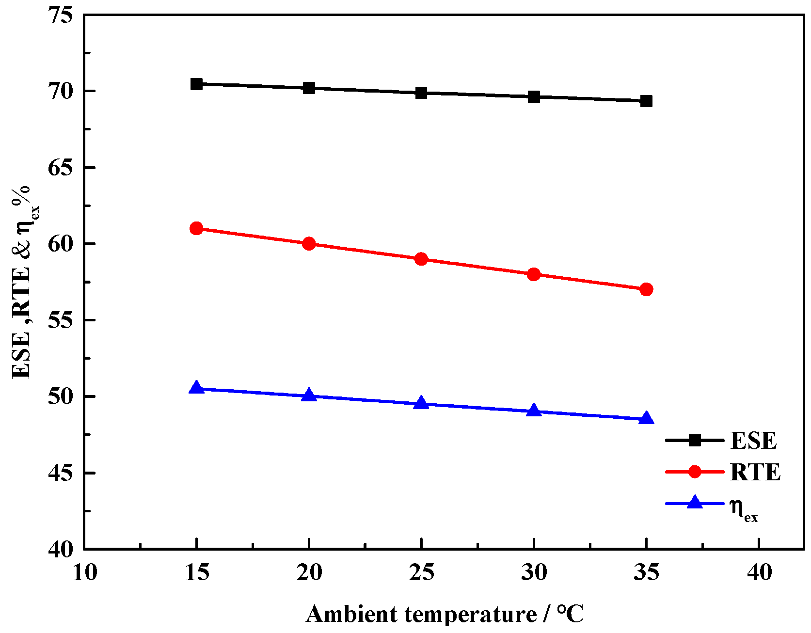
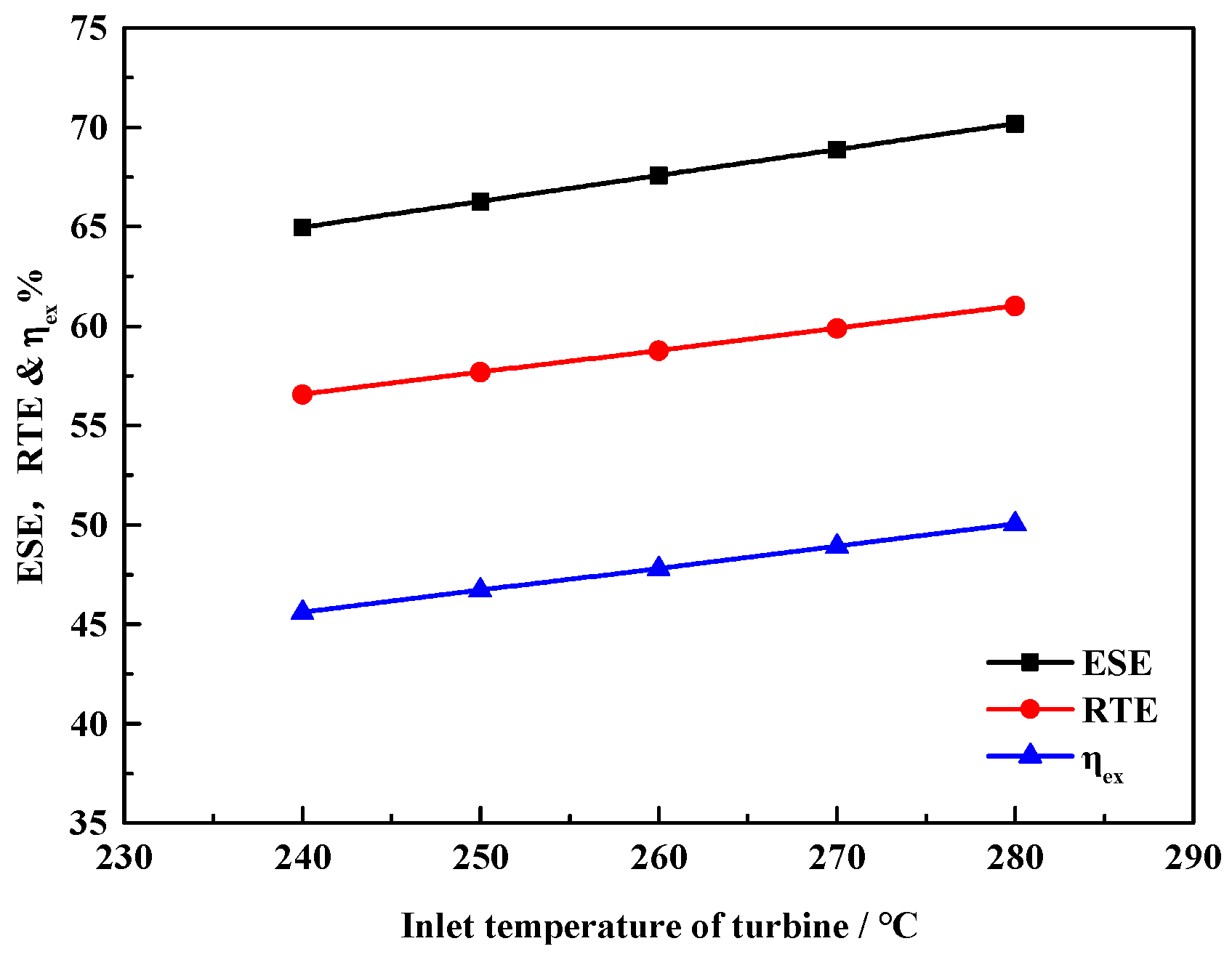
In this paper, we proposed a solar–thermal-assisted A-CAES, i.e., ST-CAES. Exhaust air preheats the compressed air, which is further heated by stable solar thermal energy, which greatly improves the performance of ST-CAES during the discharge process. In the charge process, water at ambient temperature was used to recover the compression heat and produce hot water, which provides heat for residents and reduces the power consumption of the compressor. Moreover, a mathematical model comprising energy and exergy analyses was developed. On an implementation of ST-CAES with a four-stage compression train and a three-stage expansion train, the ESE, RTE, and exergy efficiency were found to be 70.2%, 61%, and 50%, respectively. In addition, investigations of the system performance and the effects of key parameters have indicated that the turbine inlet temperature and pressure in the SPT are the critical parameters affecting the performance of the proposed ST-CAES system. Therefore, they can act as essential components in current smart grids and cities owing to the high efficiency and ability to accommodate renewables.

Author Contributions

X.C., X.X. and Q.L. conceived and designed the experiments; X.C. analyzed the data; T.Z., L.C. and S.M. revised the paper; X.C. wrote the paper.

Funding

This research Supported by the Foundation for Innovative Research Groups of the National Natural Science Foundation of China (51621065), the Scientific and Technological Project of Qinghai Province (2017-GX-101), and the Natural Science Foundation of Qinghai Province (2017-ZJ-932Q).

Conflicts of Interest

The authors declare not conflict of interests.

Nomenclature

Abbreviations
COMair compressor stage
CAEScompressed air energy storage
A-CAESadiabatic compressed air energy storage
RESrenewable energy sources
TESthermal energy storage
PHSpumped storage system
H-ACAEShybrid ACAES
TURair turbine stage
CCHPcombined cooling heating and power
HEXheat exchanger
STCsolar thermal collection and storage
PTCparabolic trough collector
HWThot water tank
HTFheat transfer fluid
CWTcold water tank
HOThigh-temperature oil tank
LOTlow-temperature oil tank
ESEelectricity storage efficiency
EXEexergy efficiency
RTEround-trip efficiency
ACair compressor
ATair turbine
OPoil pump
SPTsteel pipeline tank
TVthrottle valve
HRheat regenerator
ST-CAESsolar–thermal CAES
Greek Symbols
η efficiency (%)
β compression ratio
τtime (h)
σ Stefan–Boltzmann constant
εemissivity
Symbols
Exexergy (kW)
PPower (kW)
sspecific entropy (kJ/kg·K)
kpolytropic index
hspecific enthalpy (kJ/kg)
Qenergy (kW)
mMass flow (kg/s)
pPressure (MPa)
Ttemperature (°C)
Uheat transfer coefficient
Rgas constant
Subscripts
0ambient condition
i, jstate point
sisentropic
uuseful
Rreflection
opoptical
LLoss
ininput
outoutput
ababsorber
chcharging
dchdischarging
gglass
Ddirect normal irradiation
ccollecting hour
hsheat supply
convconvection
radradiation
condconduction
Streams
ARair stream
Ooil stream
WAwater stream

References

  1. Sun, J.; Wang, Z.; Li, G. Measuring emission-reduction and energy-conservation efficiency of Chinese cities considering management and technology heterogeneity. J. Clean. Prod. 2018, 175, 561–571. [Google Scholar] [CrossRef]
  2. Rosiek, S.; Batlles, F.J. Renewable energy solutions for building cooling, heating and power system installed in an institutional building: Case study in southern Spain. Renew. Sustain. Energy Rev. 2013, 26, 147–168. [Google Scholar] [CrossRef]
  3. Bitaraf, H.; Rahman, S. Reducing Curtailed Wind Energy through Energy Storage and Demand Response. IEEE Trans. Sustain. Energy. 2018, 9, 228–236. [Google Scholar] [CrossRef]
  4. Inage, S.I. Prospects for Large-Scale Energy Storage in Decarbonized Power Grids; International Energy Agency IEA: Paris, France, 2009. [Google Scholar]
  5. Wind Power Curtailment in China on the Mend-Renewable Energy World. Available online: https://www.renewableenergyworld.com/articles/2018/01/wind-power-curtailment-in-china-on-the-mend.html (accessed on 15 August 2018).
  6. Liu, Z. Global Energy Interconnection; China Electric Power Press: Beijing, China, 2015; pp. 85–86. [Google Scholar]
  7. Luo, X.; Wang, J.; Dooner, M.; Clarke, J. Overview of current development in electrical energy storage technologies and the application potential in power system operation. Appl. Energy 2015, 137, 511–536. [Google Scholar] [CrossRef]
  8. Lund, H.; Salgi, G. The role of compressed air energy storage (CAES) in future sustainable energy systems. Energy Convers. Manag. 2009, 50, 1172–1179. [Google Scholar] [CrossRef]
  9. Chen, L.; Zheng, T.; Mei, S.; Xue, X.; Liu, B.; Lu, Q. Review and prospect of compressed air energy storage system. J. Mod. Power Syst. Clean Energy 2016, 4, 529–541. [Google Scholar] [CrossRef]
  10. Budt, M.; Wolf, D.; Span, R.; Yan, J. A review on compressed air energy storage: Basic principles, past milestones and recent developments. Appl. Energy 2016, 170, 250–268. [Google Scholar] [CrossRef]
  11. Raju, M.; Khaitan, S.K. Modeling and simulation of compressed air storage in caverns: A case study of the Huntorf plant. Appl. Energy 2012, 89, 474–481. [Google Scholar] [CrossRef]
  12. Wang, J.; Lu, K.; Ma, L.; Wang, J.; Dooner, M.; Miao, S.; Jian, L.; Wang, D. Overview of Compressed Air Energy Storage and Technology Development. Energies 2017, 10, 991. [Google Scholar] [CrossRef]
  13. Hartmann, N.; Vöhringer, O.; Kruck, C.; Eltrop, L. Simulation and analysis of different adiabatic Compressed Air Energy Storage plant configurations. Appl. Energy 2012, 93, 541–548. [Google Scholar] [CrossRef]
  14. Mei, S.; Wang, J.; Tian, F.; Chen, L.; Xue, X.; Lu, Q.; Zhou, Y.; Zhou, X. Design and engineering implementation of non-supplementary fired compressed air energy storage system: TICC-500. Sci. China Technol. Sci. 2015, 58, 600–611. [Google Scholar] [CrossRef]
  15. Wang, S.; Zhang, X.; Yang, L.; Zhou, Y.; Wang, J. Experimental study of compressed air energy storage system with thermal energy storage. Energy 2016, 103, 182–191. [Google Scholar] [CrossRef]
  16. Mei, S.; Gong, M.; Qin, G.; Tian, F.; Xue, X.; Li, R. Advanced Adiabatic Compressed Air Energy Storage System with Salt Cavern Air Storage and Its Application Prospects. Power Syst. Technol. 2017. [Google Scholar] [CrossRef]
  17. Grazzini, G.; Milazzo, A. Thermodynamic analysis of CAES/TES systems for renewable energy plants. Renew. Energy 2008, 33, 1998–2006. [Google Scholar] [CrossRef] [Green Version]
  18. Yang, C.; Wang, X.; Huang, M.; Ding, S.; Ma, X. Design and simulation of Gas Turbine-Based CCHP Combined with Solar and Compressed Air Energy Storage in a hotel Building. Energy Build. 2017, 153, 412–420. [Google Scholar] [CrossRef]
  19. Arabkoohsar, A.; Dremark-Larsen, M.; Lorentzen, R.; Andresen, G.B. Subcooled compressed air energy storage system for coproduction of heat, cooling and electricity. Appl. Energy 2017, 205, 602–614. [Google Scholar] [CrossRef]
  20. Ji, W.; Zhou, Y.; Sun, Y.; Zhang, W.; An, B.; Wang, J. Thermodynamic analysis of a novel hybrid wind-solar-compressed air energy storage system. Energy Convers. Manag. 2017, 142, 176–187. [Google Scholar] [CrossRef]
  21. Xu, Y.; Chen, H.; Liu, J.; Tan, C. Performance analysis on an integrated system of compressed air energy storage and electricity production with wind-solar complementary method. Proc. CESS 2012, 32, 88–95. [Google Scholar]
  22. Semprini, S.; Sánchez, D.; Pascale, A.D. Performance analysis of a micro gas turbine and solar dish integrated system under different solar-only and hybrid operating conditions. Sol. Energy 2016, 132, 279–293. [Google Scholar] [CrossRef]
  23. Mohammadi, A.; Mehrpooya, M. Exergy analysis and optimization of an integrated micro gas turbine, compressed air energy storage and solar dish collector process. J. Clean. Prod. 2016, 139, 372–383. [Google Scholar] [CrossRef]
  24. Yang, G.; Zhai, X. Optimization and performance analysis of solar hybrid CCHP systems under different operation strategies. Appl. Therm. Eng. 2018, 133, 327–340. [Google Scholar] [CrossRef]
  25. Li, R.; Chen, L.; Yuan, T.; Li, C. Optimal Dispatch of Zero-Carbon Emission Micro Energy Internet Integrated with Non-Supplementary Fired Compressed Air Energy Storage System. J. Mod. Power Syst. Clean Energy 2016, 4, 566–580. [Google Scholar] [CrossRef]
  26. Mei, S.; Li, R.; Xue, X.; Chen, Y.; Lu, Q.; Chen, X.; Ahrens, C.; Li, R.; Chen, L. Paving the Way to Smart Micro Energy Internet: Concepts, Design Principles, and Engineering Practices. CSEE J. Power Energy Syst. 2017, 3, 440–449. [Google Scholar] [CrossRef]
  27. Nation, D.D.; Heggs, P.J.; Dixon-Hardy, D.W. Modelling and simulation of a novel Electrical Energy Storage (EES) Receiver for Solar Parabolic Trough Collector (PTC) power plants. Appl. Energy 2017, 195, 950–973. [Google Scholar] [CrossRef] [Green Version]
  28. Forristall, R. Heat Transfer Analysis and Modeling of a Parabolic trough Solar Receiver Implemented in Engineering Equation Solver; National Renewable Energy Laboratory: Golden, CO, USA, 2003.
  29. Powell, K.M.; Edgar, T.F. Modeling and control of a solar thermal power plant with thermal energy storage. Chem. Eng. Sci. 2012, 71, 138–145. [Google Scholar] [CrossRef]
  30. Zeroual, B.; Moummi, A. Design of parabolic trough collector solar field for future solar thermal power plants in Algeria. In Proceedings of the 2nd International Symposium on Environment Friendly Energies and Applications, Newcastle upon Tyne, UK, 25–27 June 2012; pp. 168–172. [Google Scholar] [CrossRef]
  31. Farzad, J.; Emad, A.; Hossein, A. Energy and exergy efficiency of heat pipe evacuated tube solar collectors. Therm. Sci. 2016, 20, 150. [Google Scholar]
  32. Huang, D. Analysis on Exergy in the Photo-thermal Conversion Process of Trough Type Solar Collector. Hydropower New Energy 2014. [Google Scholar] [CrossRef]
  33. Zunft, S.; Freund, S. Large-scale Electricity Storage with Adiabatic CAES—The ADELE-ING project. In Proceedings of the Energy Storage Global Conference, Paris, France, 19–21 November 2014. [Google Scholar]
  34. Kalogirou, S.A. Solar thermal collectors and applications. Prog. Energy Combust. Sci. 2004, 30, 231–295. [Google Scholar] [CrossRef]
  35. Hachicha, A.A.; Rodríguez, I.; Capdevila, R.; Oliva, A. Heat transfer analysis and numerical simulation of a parabolic trough solar collector. Appl. Energy 2013, 111, 581–592. [Google Scholar] [CrossRef] [Green Version]
Figure 1. The design scheme of ST-CAES.
Applsci 08 01390 g001
Figure 2. Parabolic trough collector thermal model.
Applsci 08 01390 g002
Figure 3. Exergy efficiencies of each subsystem.
Applsci 08 01390 g003
Figure 4. Exergy destruction of each subsystem.
Applsci 08 01390 g004
Figure 5. Effect of ambient temperature on WCOM, WTUR, and PSPT.
Applsci 08 01390 g005
Figure 6. Effect of ambient temperature on ESE, RTE, and ηex.
Applsci 08 01390 g006
Figure 7. Effect of air turbine inlet temperature on WCOM, WTUR, and VP-1 mass flow.
Applsci 08 01390 g007
Figure 8. Effect of inlet air turbine temperature on ESE, RTE, and ηex.
Applsci 08 01390 g008
Figure 9. Effect of SPT minimum pressure on PTUR and operation time.
Applsci 08 01390 g009
Figure 10. Effect of SPT minimum pressure on ESE, RTE, and ηex.
Applsci 08 01390 g010
Figure 11. Effect of SPT maximum pressure on PCOM and operation time.
Applsci 08 01390 g011
Figure 12. Effect of SPT maximum pressure on ESE, RTE, and ηex.
Applsci 08 01390 g012
Table 1. Key design factors of PTC.
Key Parameters of PTCCorresponding Data
Mirror typeUltra-white float glass
Optical efficiency at 0 degrees incidence75%
Reflector length per row (m)13.12
Number of reflector rows8
Aperture width (m)1
Specular reflectivity0.94
Absorber tube emissivity0.15
Glass envelope emissivity0.9
Glass tube support fin efficiency5%
Table 2. Expressions of input and output exergy of each subsystem.
SubsystemExinExout
ACWCOM + ExAR3 + ExAR5 + ExAR7ExAR2 + ExAR4 + ExAR6 + ExAR8
HEX of COMExAR2+ ExAR4+ ExAR6+ ExAR8+ ExWA1+ ExWA3+ ExWA5+ ExWA7ExAR3+ ExAR5+ ExAR7+ ExAR9+ ExWA2+ ExWA4+ ExWA6+ ExWA8
STCExQuExO3 − ExO2
ATExAR12+ ExAR14+ ExAR16WTUR +ExAR13+ ExAR15+ ExAR17
HEX of TURExAR10+ ExAR17+ ExAR11+ ExAR13+ ExAR15+ ExO5ExAR11+ ExAR18+ ExAR12+ ExAR14+ ExAR16+ ExO12
SPTExAR9ExAR10
Table 3. Basic design parameters of ST-CAES system.
ParametersUnitsValues
Ambient pressureMPa0.1
Ambient temperature°C20
Compression stage/4
Expansion stage/3
Compressor exhaust pressureMPa10
Inlet pressure of air turbineMPa6.9
Inlet temperature of air turbine°C280
τchh4
τdchh4
Mass flow rate of air-fluidkg/s0.56
Mass flow rate of VP-1 to PTCkg/s0.54
Temperature of hot water°C80
Temperature of return water°C30
Adiabatic efficiency of air compressor%90
Adiabatic efficiency of air turbine%85
Inlet temperature of cooling water°C20
Volume of stored air tankm33000
Range of temperature with hot oil tank°C300~305
Direct normal irradianceW/m2841.1
Solar heat storage durationh6
Hot water supplying durationh8
Efficiency of heat collection%68.18
Solar hours/dayh12/173 (22 June)
Total effective aperturem299.7
Table 4. Simulation results of the ST-CAES system under typical operational conditions.
ParametersUnitValues
Compressor power consumptionkW329.9
Air turbine electricity generationkW231.5
Collection power of PTCkW213.3
Mass flow rate of VP-1 to TURkg/s2.75
Mass flow rate of cooling waterkg/s1.36
Production the mass of hot waterton20
Electricity storage efficiency%70.2
Round-trip efficiency%61
Exergy efficiency%50
Table 5. Thermodynamic parameters of air stream.
StreamT (°C)P (MPa)h (kJ/kg)s (kJ/kg·K)Ex (kJ/kg)m (kg/s)
AR1200.12946.840.000.56
AR21500.3425.146.88120.730.56
AR3400.3313.686.5897.100.56
AR4178.51.0453.716.61226.560.56
AR5401.0312.296.25193.060.56
AR6181.43.3455.146.28325.420.56
AR7403.2307.975.90290.320.56
AR8179.510.2449.225.93421.510.56
AR94010.0295.955.53385.420.56
AR10206.9278.935.58353.630.56
AR111006.9366.315.85363.680.56
AR122806.7557.596.27430.600.56
AR13131.61.7404.976.35253.950.56
AR142801.7558.596.68311.160.56
AR15132.20.4406.936.76135.850.56
AR162800.4558.927.09192.530.56
AR17124.50.1399.467.1515.280.56
AR1834.50.1308.596.890.350.56
Table 6. Thermodynamic parameters of water and Therminol VP-1 stream.
StreamT (°C)P (MPa)h (kJ/kg)s (kJ/kg·K)Ex (kJ/kg)m (kg/s)
O11150.113.77−2.7214.530.54
O2115.20.414.30−2.7214.900.54
O33050.1633.92−1.48273.060.54
O43000.2346.60−2.03144.640.76
O53000.1624.90−1.50268.910.76
O63000.1624.90−1.50268.910.26
O7102.80.1−3.36−2.7610.540.26
O83000.1624.90−1.50268.910.25
O9134.30.142.11−2.6521.990.25
O103000.1624.90−1.50268.910.25
O111350.143.16−2.6422.220.25
O12123.80.126.50−2.6917.870.76
WA1200.184.010.300.000.24
WA2800.1335.061.0822.660.24
WA3200.184.010.300.000.31
WA4800.1335.061.0822.660.31
WA5200.184.010.300.000.32
WA6800.1335.061.0822.660.32
WA7200.184.010.300.000.49
WA8800.1335.061.0822.660.49
WA9800.1335.061.0822.661.36
WA10200.184.010.300.001.36
WA11800.2335.131.0822.760.66
WA12300.2125.910.4340.270.66
Table 7. The comparison of performance of ST-CAES to hybrid A-CAES.
ParametersUnitST-CAESHybrid A-CAES
Compressor power consumptionkWh1361.5152.1
Charging timeh46.59
Discharging timeh45.13
With/without TES/Yesno
Expansion train working period load peak hoursIrradiation peak hours
Inlet temperature of air turbine°C280900
Air turbine electricity generationkWh949.1228.54
Round trip efficiency%6176.5
Exergy efficiency%5053.4

