Article

Simulation of Motion Interactions of a 2-DOF Linear Piezoelectric Impact Drive Mechanism with a Single Friction Interface

School of Instrument Science and Opto-electronics Engineering, Hefei University of Technology, Hefei 230009, China
*
Authors to whom correspondence should be addressed.
Haojie Xia and Liling Han contributed equally to this work.
Submission received: 20 July 2018 / Revised: 16 August 2018 / Accepted: 16 August 2018 / Published: 19 August 2018
(This article belongs to the Special Issue Piezoelectric Actuators)

Abstract

:

Featured Application

This study provides theoretical and technical references for the practical development of a parallel piezoelectric impact drive mechanism. A controllable complex curve motion can be realized by the method of using coupled motions.

Abstract

A two-degrees-of-freedom (2-DOF) linear piezoelectric impact drive mechanism (PIDM) is actuated by two independent piezoelectric actuators (PAs). The coupled motion interactions of a two orthogonal DOF linear PIDM with a single friction interface are introduced and analyzed. A complete dynamic model of the 2-DOF PIDM is established with the Karnopp friction model considering the distribution of friction in the x-axis and y-axis. The output displacements of the 2-DOF PIDM and two corresponding independent 1-DOF PIDMs are investigated numerically. When the two input exciting signals of a 2-DOF PIDM have the same driving voltage of 100 V with a duty ratio of 98% at 10 Hz and two 1-DOF PIDMs are driving under the same conditions, the step displacements in the two axes of 2-DOF PIDM are improved compared to the corresponding 1-DOF PIDM. When the two input exciting signals of a 2-DOF PIDM have the same driving voltages of 100 V with a duty ratio of 98% but the driving frequency is 10 Hz in the x-axis and 20 Hz in the y-axis, the results show that the displacement of high frequency achieves a slight decrease and displacement of low frequency shows a large increase compared to the two corresponding 1-DOF PIDMs.

Graphical Abstract

1. Introduction

Because piezoelectric impact drive mechanisms (PIDMs) have a compact structure, high positioning accuracy, and a long stroke, they have been widely used in the fields of precision positioning [1,2]. Multiple-degrees-of-freedom (DOF) motions of stages and manipulators with PIDMs can achieve flexible and wide control in actuators. Multi-DOF motions of PIDM can be designed in two structures. The first kind of structure is the complex structure in series [3,4,5], for which the motions are independent and their corresponding controls are relatively simple. The second kind of structure is the compact structure in parallel [6,7,8,9], for which the motions often share a common friction interface [6,8] that leads to a coupled motion when the motions are operated at the same time [8,10]. Recent studies on parallel PIDMs have attained multi-DOF motions by using different modes of vibration under ultrasonic driving [8,11,12,13,14,15], and studies on series PIDMs have achieved multi-DOF motions by avoiding coupled motions [4,5,16]. However, there are few studies on the coupled motion characteristics of the parallel impact PIDM [17,18].
Establishing the dynamic model of parallel multi-DOF PIDMs is foundational to understanding coupled motion interactions and estimating the influences on motion performances. PIDMs are usually combined by three basic elements: piezoelectric actuator (PAs), a stage, and a slider. The working process is a stick-slip motion with friction actuation under a sawtooth driving voltage signal [19]. In the dynamic analysis, the PA and stage are simplified as a spring–mass–damper lumped model, and the slider is considered as a mass. The motion of the slider relies on the friction between the stage and slider [20]. The friction force is nonlinear, so an accurate friction model is important to study coupled motion interactions. Many friction models, such as the Coulomb, Karnopp, LuGre, Leuven, and elastoplastic friction models, have been widely used in the friction analysis of PIDMs [21,22,23,24,25]. The Coulomb model is a basic static friction model that cannot describe friction when the relative speed is zero. The Karnopp model is an improved static friction model that provides a simple manner to avoid the detection of zero relative velocity by defining a zero velocity interval. Dynamic friction models, such as such as the LuGre, Leuven, and elastoplastic models, have high accuracy and can explain the presliding, Stribeck, and hysteretic effects, although the definitions of the model parameters are difficult [26,27,28,29,30]. The Karnopp friction model is used for analysis when the precision is low.
In this paper, a 2-DOF parallel linear PIDM is considered as the research object. A simplified model for the orthogonal motions of the PIDM is established and a two-dimensional extended Karnopp friction model is introduced. Interactions of the orthogonal motions are investigated numerically by simulations [31].

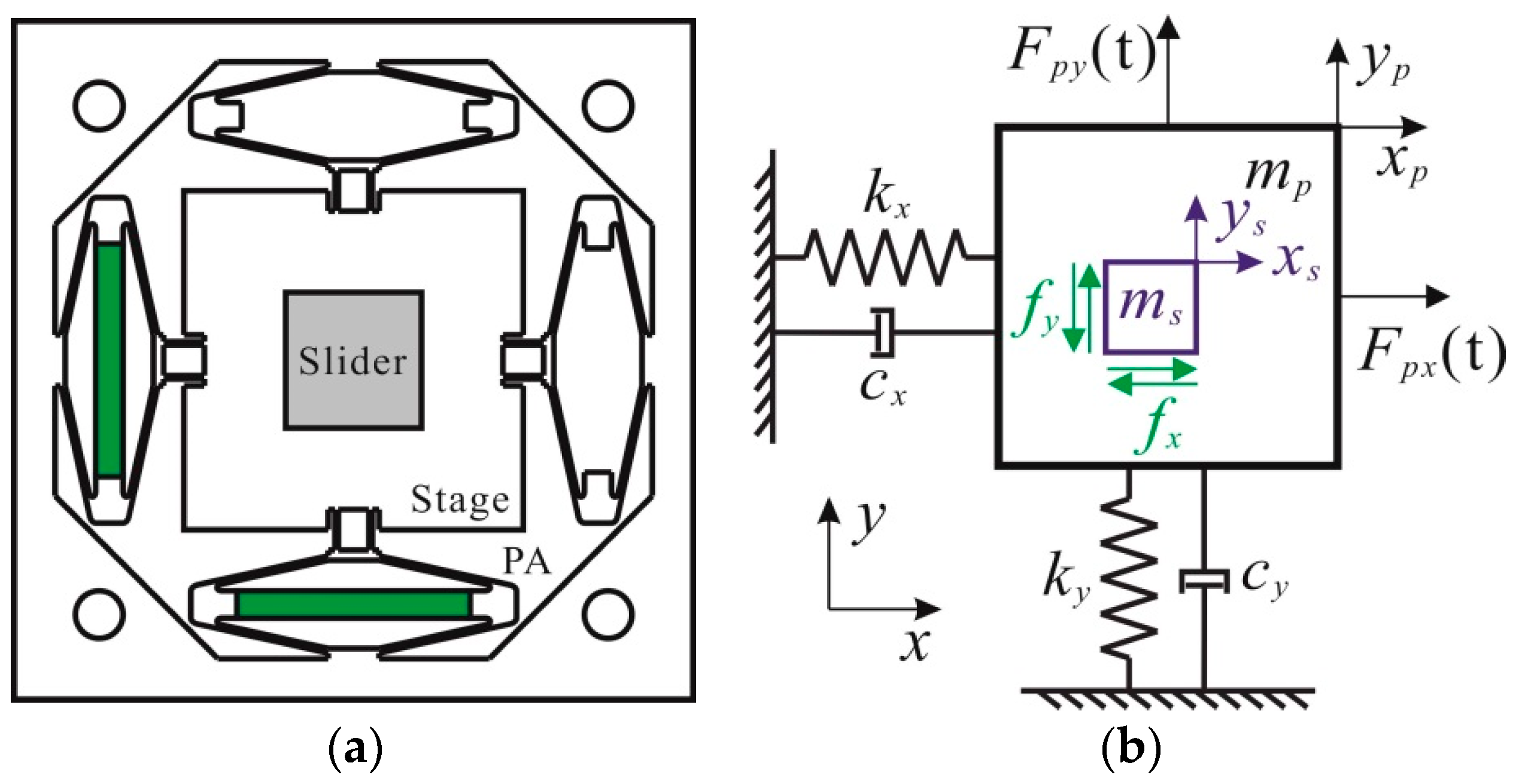
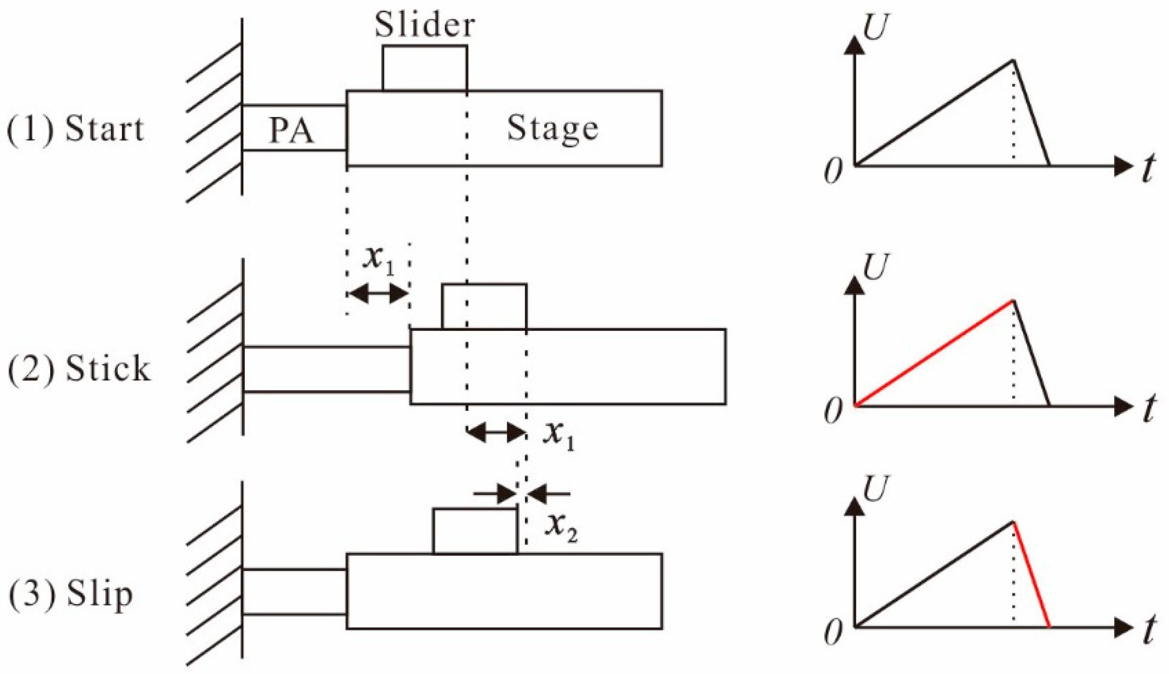
2. Structure Design, Working Process, and Dynamic Model Analysis

The proposed 2-DOF linear PIDM is shown in Figure 1a and is made up of two orthogonal PAs, a stage, and a slider. According to present studies, the 2-DOF linear PIDM can be regarded as two spring–mass–damper systems. The simplified system of the PIDM is shown in Figure 1b, where mpx is the equivalent mass of the PA and stage in the x-axis, xp is the distance of the PA in the x-axis, xs is the distance of the slider in the x-axis, kx is the stiffness of the PA and stage in the x-axis, cx is the damper of the PA and stage in the x-axis, Fpx(t) is the equivalent driving force of the PA in the x-axis, fx is the friction force in the x-axis, msx is the mass of the slider in the x-axis, mpy is the equivalent mass of the PA and stage in the y-axis, yp is the distance of the PA in the y-axis, ys is the distance of the slider in the y-axis ky is the stiffness of the PA and stage in the y-axis, cy is the damper of the PA and stage in the y-axis, Fpy(t) is the equivalent driving force of the PA in the y-axis, fy is the friction force in the y-axis, and msy is the mass of the slider in the y-axis [32,33].
Kinematics equations of the 2-DOF orthogonal motions in the parallel 2-DOF PIDM can be extended from the 1-DOF PIDM model [34] and expressed as
{ m p x x ¨ p = F p x ( t ) c x x ˙ p k x x p f x m s x x ¨ s = f x F p x ( t ) = δ x V x ( t ) ,
{ m p y y ¨ p = F p y ( t ) c y y ˙ p k y y p f y m s y y ¨ s = f y F p y ( t ) = δ y V y ( t ) ,
where the subscript x and y represent the two directions of motion and δ is the conversion coefficient between Fp(t) and driving voltage V(t).
When the x-axis and y-axis motions of the 2-DOF PIDM are driven independently, there is no coupled motion and the control is very simple. Taking the x-axis motion of 2-DOF PIDM as an example, the working principle is shown in Figure 2. One working cycle can be divided into three parts: (1) initial state: all components of the structure are still and they stay in their initial positions; (2) stick state: with the slow rise of the driving voltage, the PA extends to a length of x1 and the stage moves along the PA with the distance of x1 in a low speed as a result of the static friction force; (3) slip state: with the sudden decrease of the driving voltage, the PA contracts back to its original position quickly. The stage is adhered to the PA, so the stage moves back to its original position with a high speed. Because the slider moves by the friction force between the contact surface of the stage and slider, the speed of slider is less than the speed of the stage. Thus, the slider cannot catch the stage and it moves back with a small displacement of x2. After the working cycle, the slider moves forward with a stepping displacement of x1x2. With repeated working cycles, the slider will move forward continuously. When the driving voltage rises rapidly and falls down slowly, the slider will move backward [35].
The working principle of the y-axis is similar to the x-axis motion when the 2-DOF PIDMs are driven independently. Because the two motions share a common friction interface, the coupled motion will exist when the two PAs are working together. The study of friction distribution and the value in the x-axis and y-axis of a 2-DOF PIDM is very import. The Karnopp friction model is often used to analyze the friction force in a 1-DOF PIDM, as shown in Figure 3. A zero velocity interval is defined from −a to a; then, the Karnopp friction model [22] of a 1-DOF motion is described as follows:
f = { f c sgn ( v ) ,   | v | > a min ( f e ( t ) ,   f s ) ,   | v | a ,   f e ( t ) > 0 max ( f e ( t ) , f s ) ,   | v | a ,   f e ( t ) 0 ,
where fc is the Coulomb friction, fs is the maximum static friction, fe(t) is the external force, v is the relative velocity of the friction interface, and a is a nonzero artificial parameter.
By extending the Karnopp friction model in a 1-DOF PIDM and considering the friction distribution in the x-axis and y-axis of a 2-DOF PIDM, the value of the friction in the two directions satisfy the following formulations of a 2-DOF Karnopp friction model:
while ( x ˙ p x ˙ s ) 2 + ( y ˙ p y ˙ s ) 2 > a
{ f x = f x ˙ p x ˙ s ( x ˙ p x ˙ s ) 2 + ( y ˙ p y ˙ s ) 2 f y = f y ˙ p y ˙ s ( x ˙ p x ˙ s ) 2 + ( y ˙ p y ˙ s ) 2 f = f c ,
while ( x ˙ p x ˙ s ) 2 + ( y ˙ p y ˙ s ) 2 a
{ f x = f x ¨ p ( x ¨ p ) 2 + ( y ¨ p ) 2 f y = f y ¨ p ( x ¨ p ) 2 + ( y ¨ p ) 2 f = { m s ( x ¨ p ) 2 + ( y ¨ p ) 2 ,   m s ( x ¨ p ) 2 + ( y ¨ p ) 2 f s f s ,   m s ( x ¨ p ) 2 + ( y ¨ p ) 2 > f s ,
where f is the friction between the slider and stage.

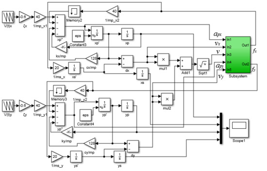
3. Numerical Simulation Processes

Assume that the spring-mass-damper system of the PA and stage has a resonant frequency of 1 kHz and a mechanical quality factor Q of 50. Through the flexure hinge amplifier based on the principle of triangle amplification, the final output displacement of one PA can be amplified to 60 μm with a driving voltage of 100 V. The driving force of the PA can be measured by the theory of spring deformation force; thus, the conversion coefficient δ can be calculated to −0.6 N∙V−1. The resonant frequency and damper ratio can be calculated according to the formulas based on free vibration as follows:
f r = 1 2 π k m p ,
ξ = 1 2 Q = c 2 k m p ,
where fr is the resonant frequency, k is the stiffness of the PA and stage, mp is the equivalent mass of the PA and stage, c is the damper of the PA and stage, and ξ is the damping ratio.
Structural parameters of the PIDM were assumed equal in the x-axis and y-axis. By choosing an appropriate slider, the parameters for numerical simulation were calculated and are listed in Table 1.
With these simulation parameters, the simulation blocks were established (Figure 4) according to the abovementioned kinematics equations [36]. The whole simulation block used a subsystem module, which included a relay module, a saturation module, and a logical operator module. Thus, it could distinguish the friction force when the system was driving under different speeds. The relay module was used to judge whether the slider was sliding on the contact surface between the slider and stage. Because the stage and PA were tightly adhered, the speed of the stage and PA were assumed to be equal. If the relative speed between the slider and PA was beyond the velocity range of a in the Karnopp friction model, the sliding friction was chosen in the kinematics equations. The sliding friction was usually equal to Coulomb friction, and if the relative speed between the slider and PA was in the velocity range of a, the static friction was chosen and used with the kinematics equations according to the logical operator module. The saturation module was used to judge whether the calculated static friction exceeded the maximum static friction. If the calculated static friction was greater than the maximum static friction, the maximum static friction was chosen. If the calculated static friction was less than the maximum static friction, the calculated static friction was chosen and used with the kinematics equations.

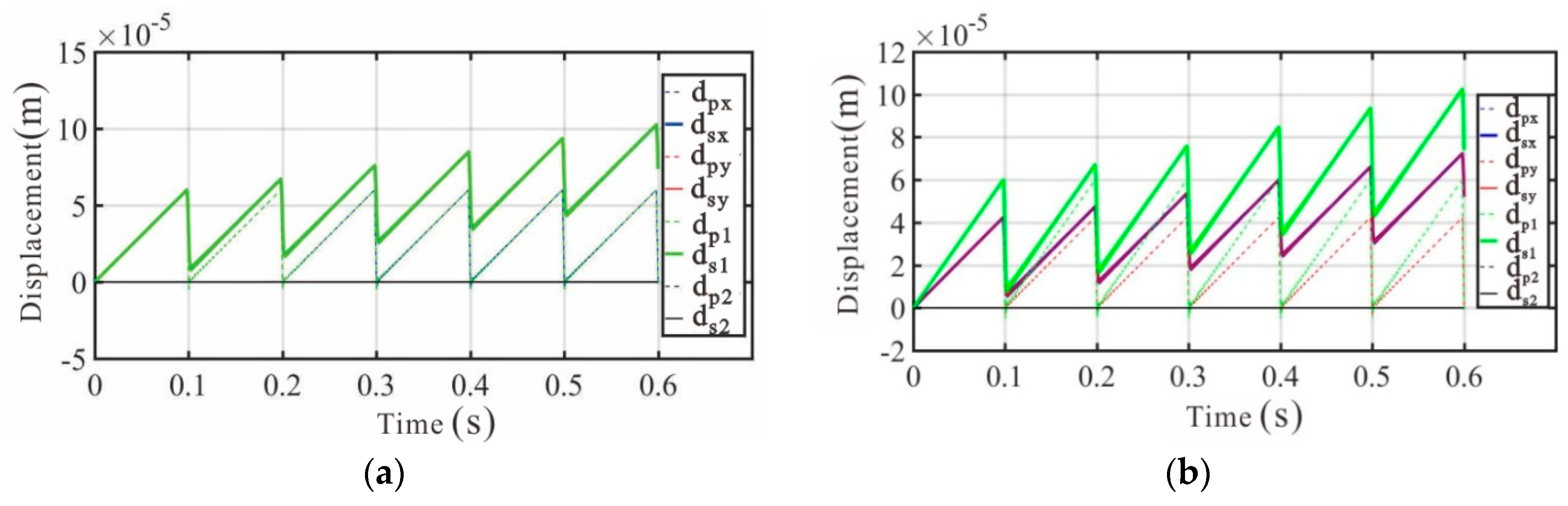
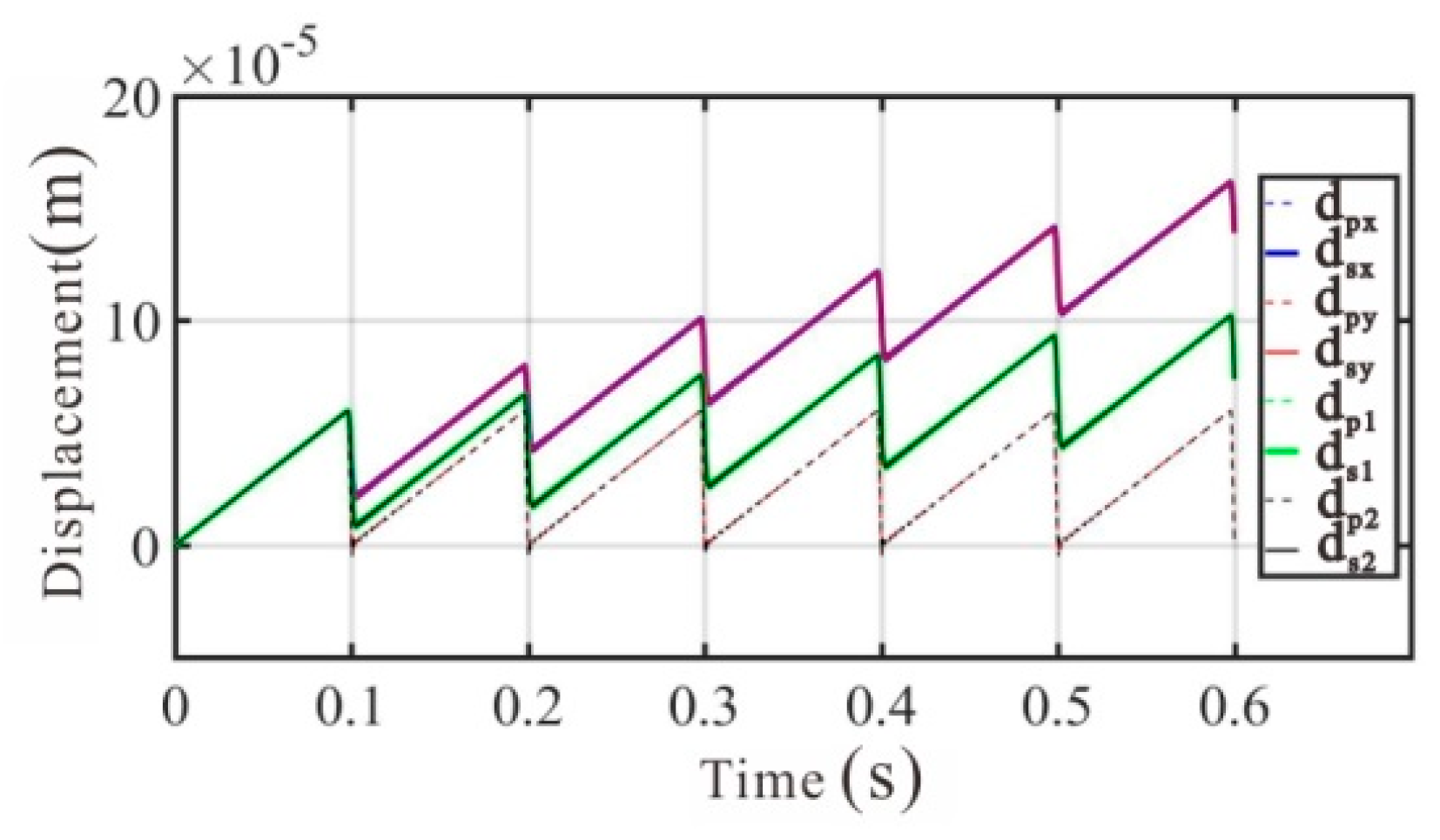
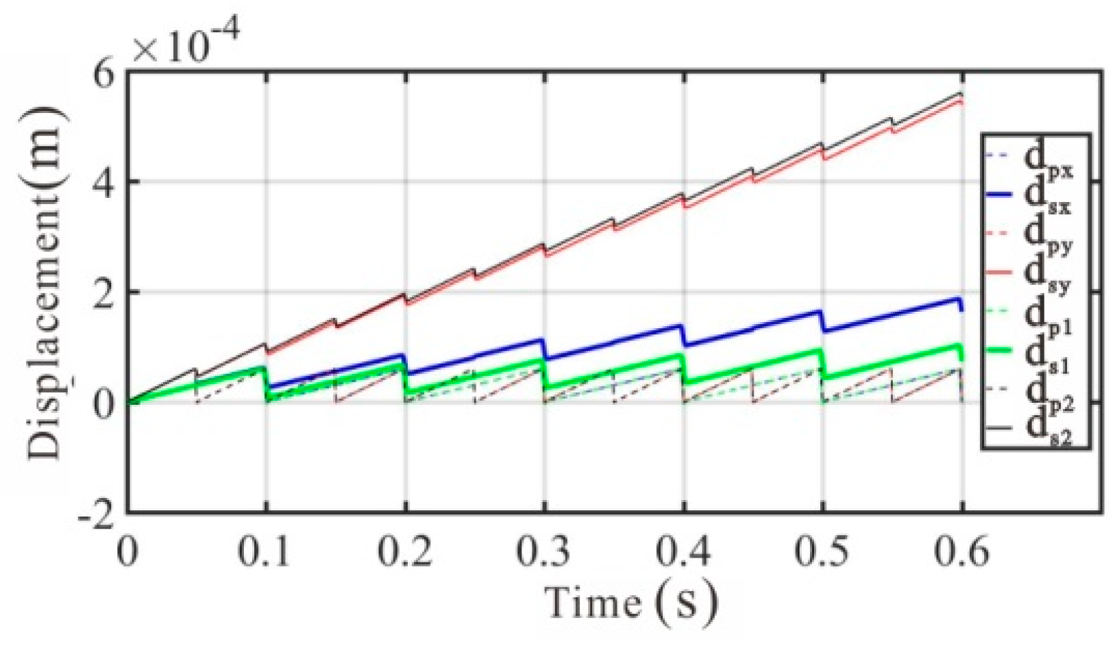
4. Simulation Results and Discussions

The output displacements of the PA and slider in the direction of the x-axis and y-axis of the 2-DOF PIDM were compared to the output displacements of the PA and slider of the two corresponding independent 1-DOF PIDMs in order to analyze the coupled motion interactions. The PAs were actuated by sawtooth driving voltage signals. The curves of output displacements of the PA in the direction of the x-axis and y-axis in the 2-DOF PIDM are shown as curve-dpx and curve-dpy, respectively. The output displacement curves of the PA are the periodic sawtooth curves (dotted curves), which are similar to the driving signals. The output displacement curves of the slider in the direction of the x-axis and y-axis in the 2-DOF PIDM are shown as curve-dsx and curve-dsy, and the output curves are usually the stepping curves (solid curves). The output displacements of the PAs and sliders in the two corresponding independent 1-DOF PIDMs are curve-dp1, curve-dp2, curve-ds1, and curve-ds2, respectively. The curve-dp1 and curve-ds1 correspond to the curves of the 2-DOF PIDM (curve-dpx and curve-dsx), which was driven by the x-axis alone. The curve-dp2 and curve-ds2 correspond to the curves of the 2-DOF PIDM (curve-dpy and curve-dsy), which was driven by the y-axis alone. According to the above principles, curve-dpx and curve-dp1 are the same dotted curves, and curve-dpy and curve-dp2 are the same dotted curves.
In order to verify the correctness of the friction distribution in the two orthogonal coupled motions, the 2-DOF PIDM was excited by a driving voltage of 100 V at a frequency of 10 Hz with a duty ratio of 98% in the direction of the x-axis and a driving voltage of 0 V at a frequency of 10 Hz with a duty ratio of 98% in the direction of the y-axis. In addition, one of the two corresponding independent 1-DOF PIDMs was excited by a driving voltage of 100 V at a frequency of 10 Hz with a duty ratio of 98%, and the other was excited by a driving voltage of 0 V. The results of the mentioned eight curves are shown in Figure 5a. The 2-DOF PIDM was driven by a voltage of 100/√2 V at the frequency of 10 Hz with duty ratio of 98% in both the direction of the x-axis and y-axis. Simultaneously, one of the two corresponding independent 1-DOF PIDMs was driven by a voltage of 100 V at a frequency of 10 Hz with duty ratio of 98%, and the other was driven by a voltage of 0 V. The results of the mentioned eight curves are shown in Figure 5b.
The results in Figure 5a show that curve-dpx and curve-dp1 are the same sawtooth curves, and the results of curve-dsx and curve-ds1 are the same output stepping displacement curves. All curves in the y direction and the corresponding 1-DOF PIDM are horizontal lines with a magnitude of 0. The results in Figure 5b show that curve-dpx and curve-dpy are the same sawtooth curves (dotted curves), and curve-dsx and curve-dsy are also the same sawtooth curves (solid curves). Figure 5b shows that the maximum value of curve-dp1 is about √2 times than that of curve-dpx (in one cycle), and the maximum value of curve-ds1 is about √2 times than that of curve-dsx (in one cycle). The results indicate that the two-dimensional extended Karnopp friction model in the 2-DOF parallel linear PIDM is correct.
The 2-DOF PIDM was driven at a frequency of 10 Hz with a voltage of 100 V and a duty ratio of 98% in both the x-axis and y-axis directions. At the same time, the two corresponding independent 1-DOF PIDMs were driven at the same conditions. The results of the mentioned eight curves are shown in Figure 6. The output of slider was important and was analyzed. The results show that the average stepping displacements of the slider for the 2-DOF PIDM in the two axes (curve-dsx and curve-dsy) are both about 19.5 μm, but the average stepping displacement of the two 1-DOF PIDMs (curve-ds1 and curve-ds2) are both about 6.0 μm. In the parallel 2-DOF PIDM, the backlash displacement of the slider was decomposed, and the stepping displacement in the two axes was improved in a circle.
The two directions of the 2-DOF PIDM were driven at the same frequency of 10 Hz with a duty ratio of 98%, but the driving voltage was 100 V in the direction of the x-axis and 50 V in the direction of the y-axis. At the same time, one of the two corresponding independent 1-DOF PIDMs was excited by a voltage of 100 V at a frequency of 10 Hz with a duty ratio of 98%, and the other was excited by a voltage of 50 V at a frequency of 10 Hz with a duty ratio of 98%. The results of the eight curves are shown in Figure 7. The average stepping displacements of the slider for the 2-DOF PIDM in the two axes (curve-dsx and curve-dsy) are about 10.8 and 5.8 μm, while the average stepping displacements of the two 1-DOF PIDMs (curve-ds1 and curve-ds2) are about 6.0 and −3.3 μm. The 2-DOF motions are quite different from the corresponding 1-DOF motions.
The two directions of the 2-DOF PIDM were excited by the same driving voltage of 100 V with a duty ratio of 98%, but the driving frequency was 10 Hz in the direction of the x-axis and 20 Hz in the direction of the y-axis. At the same time, one of the two corresponding independent 1-DOF PIDMs was excited by a driving voltage of 100 V at a frequency of 10 Hz with a duty ratio of 98%, and the other was excited by a voltage of 100 V at a frequency of 20 Hz with a duty ratio of 98%. The results of the eight curves are shown in Figure 8. The average stepping displacements of the slider for the 2-DOF PIDM in the two axes (curve-dsx and curve-dsy) are about 23.8 and 43.1 μm, while the average stepping displacements of the two 1-DOF PIDMs (curve-ds1 and curve-ds2) are 6.0 and 44.3 μm. It is obvious that the high frequency motion achieves a slight decrease and the low frequency motion obtains a large increase.
The results from Figure 6, Figure 7 and Figure 8 indicate that the coupled motion interactions of the 2-DOF parallel linear PIDM are complex and they are not a simple superposition of double 1-DOF motions.

5. Conclusions

This paper presents the coupled motion interactions of a 2-DOF parallel linear PIDM with a single friction interface. The complete dynamic model with the Karnopp friction model was established to analyze the distribution of friction force in the orthogonal directions. With different relationships of the two sawtooth driving signals, the influences of the coupled motion interactions on the 2-DOF PIDM’s performance and the two independent 1-DOF PIDMs are contrasted through numerical values. The results show that when the driving voltage or driving frequency is different in the two directions of the parallel 2-DOF linear PIDM, the value of the stepping displacement of the slider will change, and even the motion direction can turn over compared to the corresponding 1-DOF PIDM. The results mean that by using the coupled motion, the complex motion curves can be synthesized by the two directions of the 2-DOF parallel PIDM. This study provides theoretical and technical references for the practical development of a parallel piezoelectric impact drive mechanism. Thus, a controllable complex curve motion can be realized by a parallel piezoelectric impact drive mechanism.

Author Contributions

All authors conceived the structure and analyzed the data; L.H. and C.P. conducted the simulation process and studied the analysis method; H.J. analyzed the datas; all authors wrote the paper; H.X. and L.Y. contributed to revising the paper.

Funding

This research was funded by the National Natural Science Foundation of China (No. 51775157), the Natural Science Foundation of Anhui Province (No. 1608085ME108), the Project 111 (No. B12019), and the National Key Scientific Apparatus Development Project (Grant No. 2013YQ220893).

Acknowledgments

The authors would like to express their gratitude to the reviewers and editors for their kind help.

Conflicts of Interest

The authors declare no conflict of interest.

References

  1. Li, H.; Quan, Q.Q.; Deng, Z.Q.; Hua, Y.X.; Wang, Y.C.; Bai, D. A novel noncontact ultrasonic levitating bearing excited by piezoelectric ceramics. Appl. Sci. 2016, 6, 280. [Google Scholar] [CrossRef]
  2. Liu, Y.X.; Xu, D.M.; Yu, Z.Y.; Yan, J.P.; Yang, X.H.; Chen, W.S. A novel rotary piezoelectric motor using first bending hybrid transducers. Appl. Sci. 2015, 5, 472–484. [Google Scholar] [CrossRef]
  3. Zhang, Y.L.; Zhang, Y.; Ru, C.; Chen, B.K.; Sun, Y. A load-lock-compatible nanomanipulation system for scanning electron micro scope. IEEE/ASME Trans. Mechatron. 2012, 18, 230–237. [Google Scholar] [CrossRef]
  4. Sun, X.T.; Chen, W.H.; Zhang, J.B.; Zhou, R.; Chen, W.J. A novel piezo-driven linear-rotary inchworm actuator. Sens. Actuators A Phys. 2015, 224, 78–86. [Google Scholar] [CrossRef]
  5. Zhang, Y.; Zhang, W.J.; Hesselbach, J.; Kerle, H. Development of a two-degree-of-freedom piezoelectric rotary-linear actuator with high driving force and unlimited linear movement. Rev. Sci. Instrum. 2006, 77, 465–481. [Google Scholar] [CrossRef]
  6. Li, H.Y.; Wang, L.; Cheng, T.H.; He, M.; Zhao, H.W.; Gao, H.B. A high-thrust screw-type piezoelectric ultrasonic motor with three-wavelength exciting mode. Appl. Sci. 2016, 6, 442. [Google Scholar] [CrossRef]
  7. Dong, W.; Li, H.; Du, Z. A planar nano-positioner driven by shear piezoelectric actuators. Aip Adv. 2016, 6, 669–671. [Google Scholar] [CrossRef]
  8. Mashimo, T.; Toyama, S. Rotary-linear piezoelectric microactuator with a cubic stator of side length 3.5 mm. IEEE Trans. Ultrason. Ferroelectr. Freq. Control. 2010, 57, 1825. [Google Scholar] [CrossRef] [PubMed]
  9. Morita, T.; Yoshida, R.; Okamoto, Y.; Higuchi, T. Three dof parallel mechanism utilizing smooth impact drive mechanism. Precis. Eng. 2002, 26, 289–295. [Google Scholar] [CrossRef]
  10. Shim, J.Y.; Gweon, D.G. Piezo-driven metrological multiaxis nanopositioner. Rev. Sci. Instrum. 2001, 72, 4183–4187. [Google Scholar] [CrossRef]
  11. Chen, Z.; Li, X.; Liu, G.; Dong, S. A two degrees-of-freedom piezoelectric single-crystal micromotor. J. Appl. Phys. 2014, 116, 224101. [Google Scholar] [CrossRef]
  12. Guo, M.; Hu, J.; Zhu, H.; Zhao, C.; Dong, S. Three-degree-of-freedom ultrasonic motor using a 5-mm-diameter piezoelectric ceramic tube. IEEE Trans. Ultrason. Ferroelectr. Freq. Control. 2013, 60, 1446–1452. [Google Scholar] [CrossRef]
  13. Lee, D.J.; Lee, S.K. Ultraprecision XY stage using a hybrid bolt-clamped Langevin-type ultrasonic linear motor for continuous motion. Rev. Sci. Instrum. 2015, 86, 812–818. [Google Scholar] [CrossRef] [PubMed]
  14. Liu, Y.; Yan, J.; Wang, L.; Chen, W. A two-dof ultrasonic motor using a longitudinal-bending hybrid sandwich transducer. IEEE Trans. Ind. Electron. 2018. [Google Scholar] [CrossRef]
  15. Liu, Y.; Wang, L.; Gu, Z.; Quan, Q.; Deng, J. Development of a two-dimensional linear piezoelectric stepping platform using longitudinal-bending hybrid actuators. IEEE Trans. Ind. Electron. 2018. [Google Scholar] [CrossRef]
  16. Zhang, Y.; Liu, G.; Hesselbach, J. On Development of a Rotary–Linear Actuator Using Piezoelectric Translators. IEEE/ASME Trans. Mechatron. 2006, 11, 647–650. [Google Scholar] [CrossRef]
  17. Peng, Y.; Ito, S.; Sakurai, Y.; Shimizu, Y.; Gao, W. Construction and verification of a linear-rotary microstage with a millimeter-scale range. Int. J. Precis. Eng. Manuf. 2013, 14, 1623–1628. [Google Scholar] [CrossRef]
  18. Zhu, W.L.; Zhu, Z.; Shi, Y.; Wang, X.; Guan, K.; Ju, B.F. Design, modeling, analysis and testing of a novel piezo-actuated XY compliant mechanism for large workspace nano-positioning. Smart Mater. Struct. 2016, 25, 115033. [Google Scholar] [CrossRef]
  19. Zhang, Z.M.; An, Q.; Li, J.W.; Zhang, W.J. Piezoelectric friction-inertia actuator-a critical review and future perspective. Int. J. Adv. Manuf. Technol. 2012, 62, 669–685. [Google Scholar] [CrossRef]
  20. Liu, Y.F.; Li, J.; Hu, X.H.; Zhang, Z.M.; Cheng, L.; Lin, Y.; Zhang, W.J. Modeling and control of piezoelectric inertia-friction actuators: Review and future research directions. Mechanicalences 2015, 6, 95–107. [Google Scholar] [CrossRef]
  21. Awrejcewicz, J.; Olejnik, P. Analysis of dynamic systems with various friction laws. Appl. Mech. Rev. 2005, 58, 389–411. [Google Scholar] [CrossRef]
  22. Karnopp, D. Computer simulation of stick-slip friction in mechanical dynamic systems. Trans. ASME J. Dyn. Syst. Meas. Control 1985, 107, 100–103. [Google Scholar] [CrossRef]
  23. Astrom, K.J.; Canudas-De-Wit, C. Revisiting the Lugre friction model. IEEE Control Syst. 2008, 28, 101–114. [Google Scholar] [CrossRef]
  24. Ha, J.L.; Fung, R.F.; Han, C.F.; Chang, J.R. Effects of frictional models on the dynamic response of the impact drive mechanism. J. Vib. Acoust. 2006, 128, 88–96. [Google Scholar] [CrossRef]
  25. Dupont, P.; Hayward, V.; Armstrong, B.; Altpeter, F. Single state elastoplastic friction models. IEEE Trans. Autom. Control 2002, 47, 787–792. [Google Scholar] [CrossRef]
  26. Edeler, C.; Meyer, I.; Fatikow, S. Modeling of stick-slip micro-drives. J. Micro-Nano Mechatron. 2011, 6, 65–87. [Google Scholar] [CrossRef]
  27. Peng, J.Y.; Chen, X.B. Modeling of piezoelectric-driven stick-slip actuators. IEEE/ASME 2011, 16, 394–399. [Google Scholar] [CrossRef]
  28. Nguyen, H.X.; Edeler, C.; Fatikow, S. Contact mechanics modeling of piezo-actuated stick-slip microdrives. Phys. Mesomech. 2012, 15, 280–286. [Google Scholar] [CrossRef]
  29. Ge, P.; Jouaneh, M. Generalized preisach model for hysteresis nonlinearity of piezoceramic actuators. Precis. Eng. 1997, 20, 99–111. [Google Scholar] [CrossRef]
  30. Wang, D.H.; Zhu, W.; Yang, Q. Linearization of stack piezoelectric ceramic actuators based on bouc-wen model. J. Intell. Mate Syst. Struct. 2010, 22, 401–413. [Google Scholar] [CrossRef]
  31. Karpinskii, D.N.; Parinov, I.A. Computer simulation of microstructure formation in a piezoelectric ceramic. J. Appl. Mech. Tech. Phys. 1992, 33, 134–138. [Google Scholar] [CrossRef]
  32. Nguyen, H.X.; Edeler, C.; Fatikow, S. Modeling of piezo-actuated stick-slip micro-drives: An overview. Adv. Sci. Technol. 2013, 81, 39–48. [Google Scholar] [CrossRef]
  33. Szufnarowski, F.; Schneider, A. Two-dimensional dynamics of a quasi-static legged piezoelectric actuator. Smart Mater. Struct. 2012, 21, 055007. [Google Scholar] [CrossRef]
  34. De Wit, C.C.; Olsson, H.; Astrom, K.J.; Lischinsky, P. A new model for control of systems with friction. IEEE Trans. Autom. Control 1995, 40, 419–425. [Google Scholar] [CrossRef] [Green Version]
  35. Zhao, Y.H.; Han, L.L.; Zhang, R.; Pan, C.L.; Yu, L.D. Dynamic responses of piezoelectric inertia friction motors with different friction models. In Proceedings of the 2016 Symposium on Piezoelectricity, Acoustic Waves, and Device Applications (SPAWDA), Xi’an, China, 21–24 October 2016. [Google Scholar] [CrossRef]
  36. Han, L.L.; Zhao, H.N.; Xia, H.J.; Pan, C.L.; Jiang, Y.Z.; Li, W.S.; Yu, L.D. A compact impact rotary motor based on a piezoelectric tube actuator with helical interdigitated electrodes. Sensors 2018, 18, 2195. [Google Scholar] [CrossRef] [PubMed]
Figure 1. A two-degrees-of-freedom (2-DOF) linear piezoelectric impact drive mechanism (PIDM): (a) Schematic diagram; (b) Simplified system.
Applsci 08 01400 g001
Figure 2. Working principle of 1-DOF PIDM.
Applsci 08 01400 g002
Figure 3. Karnopp friction model.
Applsci 08 01400 g003
Figure 4. Simulation block: (a) 2-DOF whole block diagram; (b) 2-DOF subsystem block diagram; (c) 1-DOF whole block diagram; (d) 1-DOF subsystem block diagram.
Applsci 08 01400 g004
Figure 5. Model comparison: (a) 2-DOF PIDM with single input; (b) The driving voltage of the 1-DOF PIDM is √2 times than that of the 2-DOF PIDM in the direction of the x-axis (y-axis).
Applsci 08 01400 g005
Figure 6. Results of two directions in the 2-DOF PIDM and the two 1-DOF PIDMs driven at the same driving signal.
Applsci 08 01400 g006
Figure 7. Results of two directions in the 2-DOF PIDM when driving under different voltages and the two 1-DOF PIDMs driving at the corresponding conditions.
Applsci 08 01400 g007
Figure 8. Results of two directions in the 2-DOF PIDM when driven under different frequencies and the two 1-DOF PIDMs driven at the corresponding conditions.
Applsci 08 01400 g008
Table 1. Parameters of the parallel 2-DOF linear PIDM.
ParameterValueUnit
mpx (mpy)2.5 × 10³kg
msx (msy)5.0 × 10³kg
kx (ky)1.0 × 10⁶N·m−1
cx (cy)3.2N·s·m−1
δx (δy)−0.6N·V−1
fs1.2N
fc1.0N
a1.0 × 10−6m·s−1

