Electro-Aero-Mechanical Model of Piezoelectric Direct-Driven Flapping-Wing Actuator


Toyota Central R&D Labs. Inc., Aichi 480-1192, Japan
*
Author to whom correspondence should be addressed.
Appl. Sci. 2018, 8(9), 1699; https://0-doi-org.brum.beds.ac.uk/10.3390/app8091699
Submission received: 31 July 2018
/
Revised: 3 September 2018
/
Accepted: 17 September 2018
/
Published: 19 September 2018
(This article belongs to the Special Issue Piezoelectric Actuators)
Abstract
:We present an analytical model of a flapping-wing actuator, including its electrical, aerodynamic, and mechanical systems, for estimating the lift force from the input electrical power. The actuator is modeled as a two-degree-of-freedom kinematic system with semi-empirical quasi-steady aerodynamic forces and the electromechanical effect of piezoelectricity. We fabricated actuators of two different scales with wing lengths of 17.0 and 32.4 mm and measured their performances in terms of the stroke/pitching angle, average lift force, and average consumed power. The experimental results were in good agreement with the analytical calculation for both types of actuators; the errors in the evaluated characteristics were less than 30%. The results indicated that the analytical model well simulates the actual prototypes.
1. Introduction
Micro aerial vehicles (MAVs) have recently attracted significant attention owing to the increasing demand for automated transport, precision agriculture, and unmanned exploration/rescue missions. Among various types of MAVs, bioinspired flapping-wing robots have attracted particular interest owing to their potential to mimic the high agility and robustness of natural insects or birds. In particular, insect or hummingbird life-scale MAVs are considered useful because their extremely low weight and small size can enable safe flight and widespread applications.
There are many candidate actuation principles for flapping-wing MAVs, including piezoelectric, electromagnetic, shape memory alloy, and electrostatic. Piezoelectric actuation appears most suitable for small-scale vehicles owing to its high power-to-weight ratio, and some studies have already used piezoelectric actuators. For example, Harvard University [1,2,3] developed “RoboBee” and demonstrated stable tethered flight of a piezoelectric-actuated vehicle with a 30-mm wing span. This robot is equipped with piezoelectric Pb(Zr,Ti)O3 (PZT) bimorph actuators and lever mechanisms to amplify and transmit the output displacement of the actuator to wings.
To realize fully untethered flight, an energy-efficient design is important. Because a flapping-wing actuator includes an electrical system, aerodynamic effects, and mechanical parts, a model integrating these three physics is required for detailed characterization. Several studies have reported mechanical-aerodynamic coupling models with nonlinear aerodynamic force [4,5] using semi-empirical quasi-steady aerodynamic theory [6,7,8,9]. The reported results showed that the models were in good agreement with experiments. In contrast to aerodynamics, the integration of electrical models has received less attention. For instance, a research group at UC Berkeley first presented an integrated model of a flapping-wing actuator that integrated the electric, aerodynamic, and mechanical parts to estimate the lift force and power consumption [10,11,12]. However, in their model, the aerodynamic force was approximated as a linear damping although it is basically nonlinear. The Harvard University research group considered the scaling of their robot on lift force, weight, and power consumption [13]. Because they focused on refining the design based on a specific prototype, their approach was heuristic, and they have not presented a deterministic model. Another group reported system modelling based on the measured response of the actuator [14]. This approach was very effective for designing a control system with an existing actuator; however, it was difficult to apply to the prediction of a newly designed actuator. A research group at the University of Southern California developed an MAV called “Robo Raven”, a larger, bird-scale vehicle, and reported the dynamic modelling of motor-driven flapping-wing MAVs and validation with flight data [15,16]. Another group at the California Institute of Technology developed “Robobat”, a bat-inspired MAV, and reported aerodynamics-based model optimization of the lift force [17]. However, these studies did not confirm the scalability of their models down to insect-scale vehicles. We believe that constructing an integrated model for an insect-scale actuation system can significantly contribute to the development of flapping-wing MAVs. Whitney et al. analyzed the conceptual design of insect-scale flapping-wing MAVs with a generalized (unspecified) actuator and aerodynamic force models [18]. They theoretically reported on how flight endurance was limited by power consumption without any experiments.
In light of the abovementioned previous studies, in the present study, we focused on the experimental validation of a flapping-wing actuator based on a piezoelectric actuation system. We present a model that integrates a flapping-wing actuator with a piezoelectric unimorph actuator and a several-tens-of-millimeter-long wings, as reported previously [19,20]. This actuator uses a direct-driven mechanism. In contrast to the mechanism used in RoboBee, this actuator does not have any amplifying transmission system; instead, a wing is directly connected to the unimorph actuator. This direct-driven mechanism was first proposed by a research group at the Army Research Laboratory [21,22], and it is advantageous in terms of structural simplicity. Two different-sized prototypes were fabricated and evaluated. We verified the theoretical model by comparing it to experimental results.
2. Electro-Aero-Mechanical Model
2.1. Direct-Driven Flapping-Wing Actuator
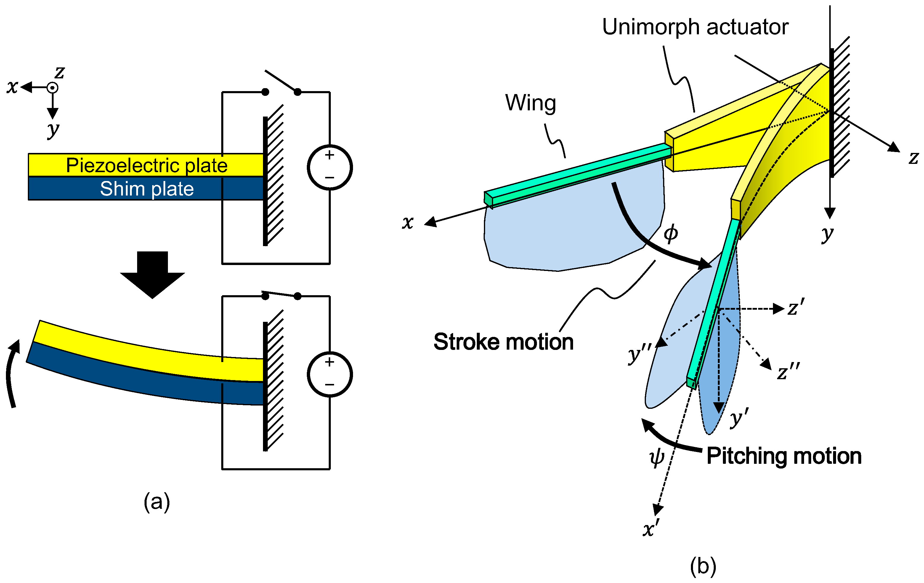
Figure 1 shows the actuation principle of a piezoelectric unimorph actuator and the structure and motion of the flapping-wing actuation system with the direct-driven mechanism. A unimorph actuator consists of a combination of a piezoelectric plate and a shim plate (elastic material), as shown in Figure 1a. Upon applying a voltage to the piezoelectric material, the actuator bends owing to the induced transverse piezoelectric stress. Figure 1b shows the structure of the flapping-wing actuation system. As described above, this system comprises only a unimorph piezoelectric actuator and a wing, and the wing is directly attached to the tip of the unimorph actuator. By actuating the unimorph, the wing is swung around the y-axis. This y-axis motion is simply called the “stroke motion”, and the stroke angle is expressed by . When the voltage signal frequency matches the resonance frequency of the system, large stroke amplitude is obtained. We define the x′y′z′-coordinate frame that rotates with the stroke motion. The wing is passively rotated around the x′-axis by air pressure associated with the stroke motion. This x′-axis rotation is called “pitching motion”, and its rotation angle is defined by . We define the x′y″z″-coordinate as a wing fixed frame. The pitching motion is crucial to generate lift force; the pitched wing gets a certain angle of attack against the stroke motion and it generates lift force along the negative y-axis. Therefore, the wing should be designed to smoothly rotate around the x′-axis and to be rigid against the other directions. For this purpose, hinge structures have often been equipped near the top edge of the wing.
In the section below, we describe the analytical model of the actuation system. To derive this model, we employ several approximations for simplicity:
- The system has only two degrees of freedom (DOFs), and . Specifically, the wing can not only rotate but also translate on the x-z plane, and therefore, this assumption is generally incorrect. However, under a cyclic resonant condition, the wing motion can be approximated as a simple rotation around a certain axis. This approximation is verified based on the experimental results reported in a later section.
- We ignore the piezoelectric and other material losses and anchor-loss because their contribution is much smaller than that of aerial damping.
We derive the model based on Lagrange’s motion equation [23]. The total kinematic energy of the system is expressed as
where , , and are the kinematic energy of the unimorph actuator, leading edge part (square bar on the top edge of the wing in Figure 1b), and wing, respectively. The total potential energy is also expressed by the sum of the elastic stored energy of the unimorph, , and the pitching hinge, , as
By using and and the aerodynamic moment along the and directions, and , respectively, the motion equation of the system can be written as
where is the Lagrangian of the system.
2.2. Mechanical Model
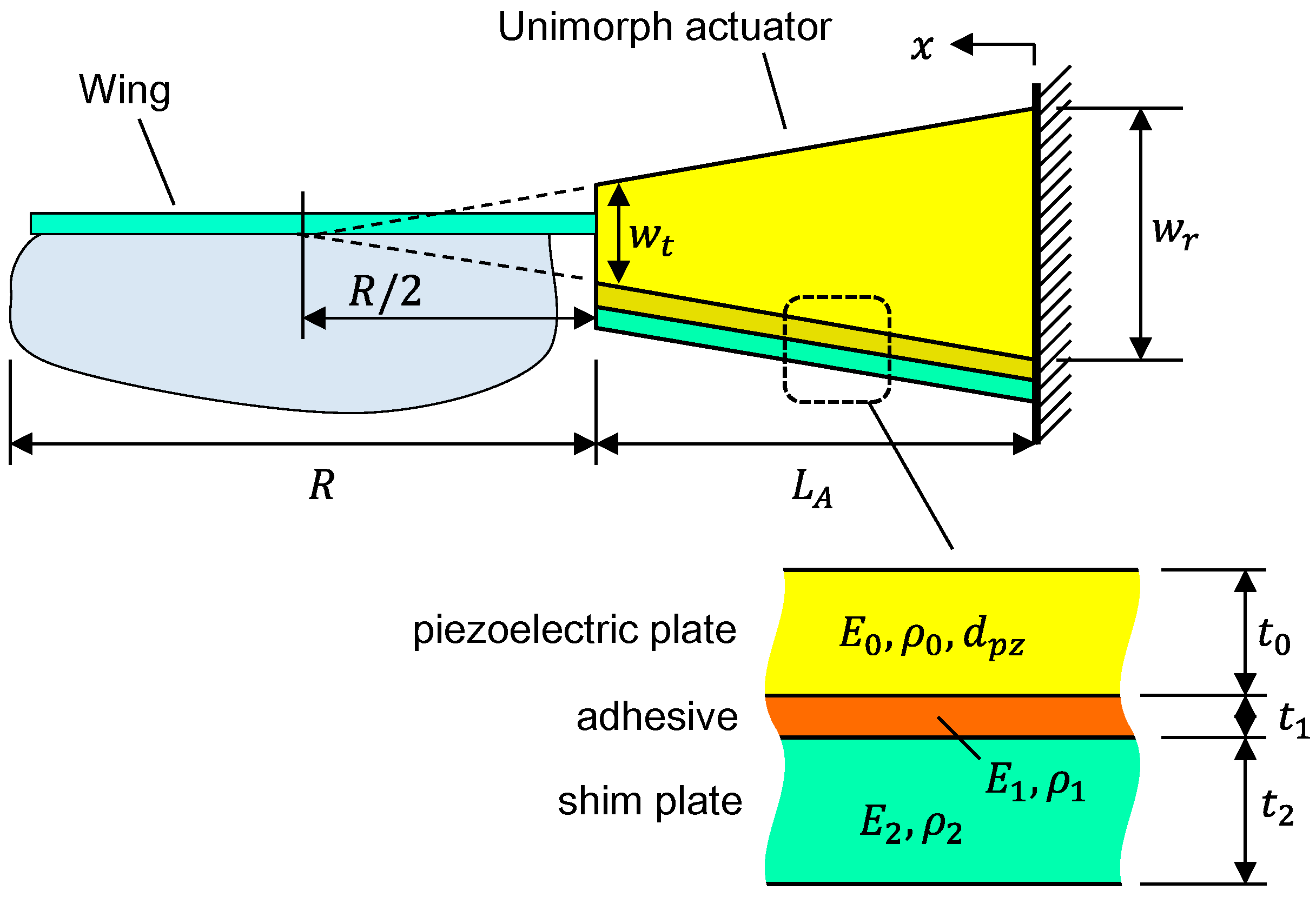
Here, we describe the derivation of and from the material and dimensional parameters of the system. Figure 2 shows the dimensions and coordinates of the system (details of the wing geometry are explained in a later section). The unimorph is designed as a trapezoid. It can reduce the stress concentration at the fixed end against inertial load and the aerodynamic force of the wing, and it can also reduce the risk of brittle fracture [24]. The cross point of the extended line of the unimorph side edges is designed to coincide with the center of the wing (, where and are the lengths of the wing and unimorph, respectively). We assumed that the rotational axis of the stroke motion is placed at . This assumption can be valid when the inertial and aerial forces of the wing are considered as concentrated forces at . Of course, this is a very rough simplification, and it is not always suitable. Thus, we check the position of the rotational center of the wing experimentally; the result is described in the Result section. By using this assumption, the curvature of the unimorph is simply expressed by as
The deflection of the unimorph can be given by
Thus, is calculated from the following integral with respect to x:
where and are the density and thickness of the i-th layer of the unimorph, respectively, as shown in Figure 2. The bending moment caused by the piezoelectric effect is given by
where and are Young’s modulus and the piezoelectric coefficient of the piezoelectric plate along the x-axis, respectively [25]. is the applied voltage to the piezoelectric material. are the z-positions of the layers of the unimorph, and they are expressed as . is the neutral axis about the bending of the unimorph, and it is expressed as
Assuming the unimorph as an Euler-Bernoulli beam [26], the curvature generated by the piezoelectric actuation is given by
where is the bending stiffness of the unimorph per unit width, and it is given by
By using and , is calculated as
Next, we describe the kinematic and potential energy of the wing. Figure 3 shows the coordinates and dimensional parameters. We newly define a coordinate as the distance from the wing root along the x-axis. is obtained as
where is the inertia of the leading edge part around the stroke rotation axis. is calculated as
where and are the mass and inertia tensor of the wing, respectively. The origin of is at the center of mass (COM) of the wing. and are the velocity of the COM and angular velocity of the wing, respectively. Upon defining these variables based on the wing-fixed x′y″z″ frame, and can be expressed by and as
and
where and are the - and -position of the COM, respectively, and is the distance between the wing root and the center axis of the stroke rotation. Upon assuming that the wing is a flat thin plate, the inertia terms with respect to x′z″ and y″z″ can be considered to be zero, and is expressed as
By substituting Equations (14)–(16) into Equation (13), is rewritten as
is defined as the spring constant of the pitching hinge, and is simply obtained as
2.3. Aerodynamics on Wing
As stated above, we model the aerodynamic force as the sum of the translational force, force due to the added-mass effect, and rotational damping. The translational forces acting on a blade element of the wing (as shown in Figure 3) are given by [9]
where and are the drag force (along z′-axis) and lift force (along y-axis), respectively. is the density of air. and are coefficients of the translational forces for and , respectively. is the angle of attack of the wing (). is the chord length of the wing. is the velocity at the center of a blade element in the z’-direction, and it is expressed as . The force component normal to the wing plane is also given by [9]
By integrating with respect to , the total translational lift force can be calculated as
where is the mean chord length (, is the area of the wing). is a nondimensional geometrical parameter of the wing, and it is defined as
where , , and . In the integration in Equation (21), we approximated as being uniform for the entire wing; we replaced with , where is the value of at . This approximation can become invalid when the wing spins around itself; however, we concluded that it is acceptable because such motion is rare in the intended flapping behavior.
The translational moment about the pitching (x’-axis) is also derived by integration with respect to as
where is the normalized center position of the air pressure. Dickson et al. reported that it can be estimated as [8]
The translational moment about the stroke (y-axis) is obtained in a similar way:
The translational coefficients are calculated using the equations below [4,27]:
where we used and based on [4].
The force due to the added-mass effect on a blade element is expressed as [5,6,7,8,9]
where is the normal component of the wing velocity: . is obtained by a time-derivative of as . The total force is obtained by integration as
acts along the z″-axis (normal direction of the wing). The added-mass moment about the pitching x′-axis and y″-axis are respectively given by
and
The moment due to the rotational damping on a blade element is calculated as [4]
where is a constant coefficient. Different values of 2.0–5.0 were used, as reported in several previous studies as well [4,28,29]. In this study, we used = 3.5. Upon integrating , the total moment can be expressed as
where is a constant that depends on the wing geometry as follows:
and are respectively given by
The total lift force is given by
2.4. Electrical Model of Unimorph Actuator
The current flow into the actuator is given by a time-derivative of the sum of the charge due to the static capacitance, , and the charge due to the dynamic piezoelectric effect, , as
and are respectively calculated by integrating charge densities along the unimorph longitudinal direction as [30]
and [30]
where is the permittivity of the piezoelectric plate. By substituting Equations (37) and (38) into Equation (36), can be rewritten as
and the consumed power of the system is obtained as
By using the above equations (Equations (6), (11)–(13), (18), and (34)), the motion equation (Equation (3)) is expressed by known parameters and . Therefore, by giving a certain initial condition and a prescribed , the motion of the system can be calculated by integrating Equation (3). In this study, we numerically performed the integration using the built-in function for ordinary differential equations, NDSolve, in Mathematica (Wolfram). The total lift force and consumed power are obtained by substituting the calculated motion, and , and into Equations (33) and (38).
3. Experiment
3.1. Design and Fabrication
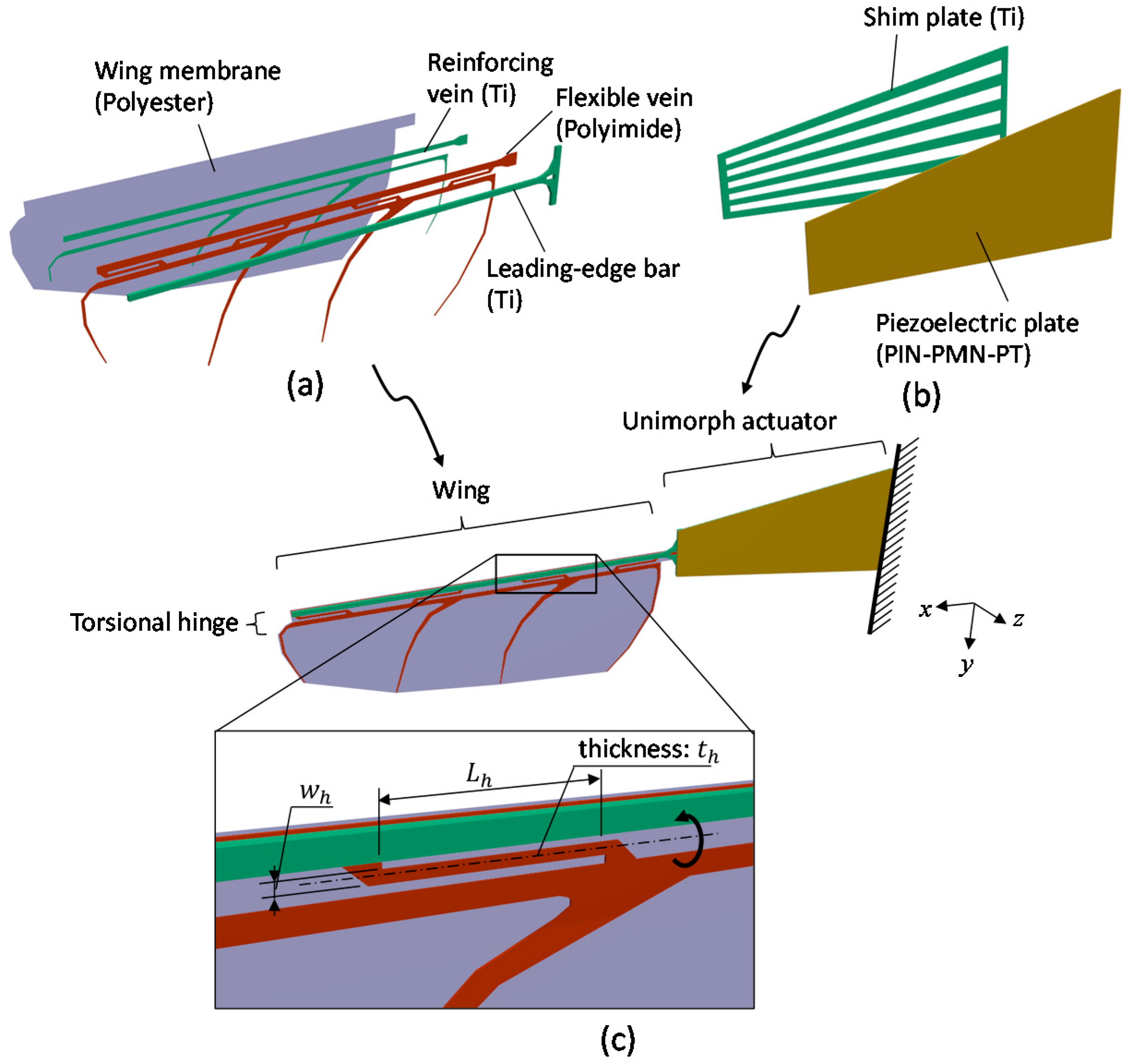
To verify the analytical model, we measured the performance of prototypes of the flapping-wing actuation system and compared the result to the analytical calculation. Figure 4 shows the structure of the system. The system comprises two parts: a piezoelectric unimorph actuator and a wing. The wing comprises four parts (shown in Figure 4a): Leading-edge bar, flexible vein, reinforcing vein, and wing membrane. The wing membrane is a thin polyester film, and it is supported by the veins. The veins consist of a combination of titanium (Ti) reinforcing layer and polyimide (PI) flexible layer. The wing can rotate around the x-axis at the hinge structure, which is also made of the PI layer. A magnified drawing of the hinge structure is shown in Figure 4c. The hinge of the prototype comprises a torsional beam structure. Thus, can be calculated simply as the spring constant of the torsional beams [31]:
where and are the number of torsional beams and the shear modulus of PI, respectively. , , and are the thickness, width, and length of the torsional beams, respectively. The unimorph actuator consists of a piezoelectric plate and a Ti shim plate bonded by epoxy adhesive (shown in Figure 4b). We used a Pb(In1/2Nb1/2)O3-Pb(Mg1/3Nb2/3)O3-PbTiO3 (PIN-PMN-PT) single crystal as the piezoelectric material; it is suitable for large-displacement actuators because of its extremely high piezoelectric coefficient. PIN-PMN-PT plates were obtained from TRS Technologies (United States). The Ti shim plate has slits along the longitudinal direction to let excess adhesive flow out.
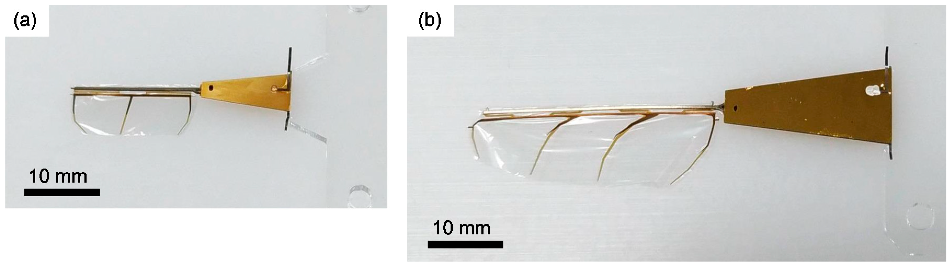
In this experiment, two prototypes with different size were measured for confirming the generality of the model. One has a 17.0-mm-long wing and a 10.5-mm-long unimorph and the other has a 32.4-mm-long wing and a 21.0-mm-long unimorph; they are respectively called “small type” and “large type” below. The other design parameters and material properties are summarized in Appendix A. Figure 5 shows photographs of the small and large types.
3.2. Measurement
Figure 6 shows the experimental setup for the wing motion, lift force, and power consumption. We captured the wing motion using an experimental setup with a high-speed camera. The average lift force and consumed power were measured using a precise electrical balance (HR-100A, A&D Co., Tokyo, Japan) and a power analyzer (PA1000, Tektronix, Beaverton, United States), respectively. To block the wind produced by the wing, an acrylic plate was placed between the wing and the electric balance.
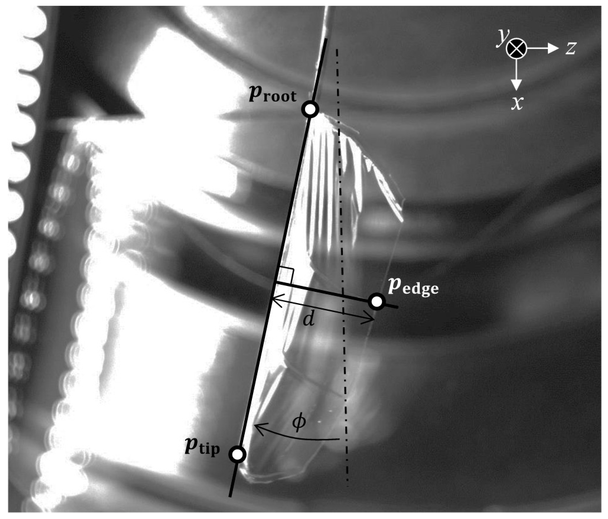
Figure 7 shows a typical image of the actuated wing. We tracked the tip and root and the tip position of the leading edge, and , respectively, and a position on the lower edge of the wing, , based on the images to estimate and . was simply calculated as the angle between and the x-axis. was estimated by
where and are the distance between the leading edge and in the image and the chord length at the measured point, respectively. We applied unipolar sinusoidal driving signals with amplitude of : . In this experiment, the maximum voltages for the small and large types were 30 and 50 V, respectively, to prevent fracture of the piezoelectric material. The frequency of the voltage signal was matched to the resonance frequency of the system.
4. Results and Discussion
4.1. Center Position of Stroke Motion
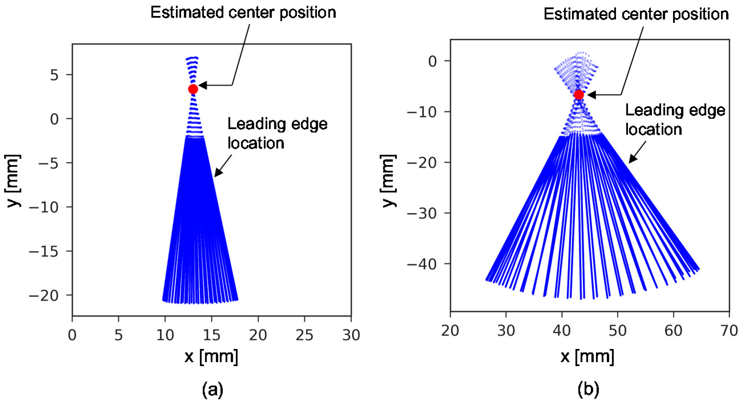
We estimated the rotational center position, , of the wing to check whether approximation 1 is acceptable. The center positions were determined as the nearest position from lines through and . Specifically, we solved the following problem:
where and are the positions in the i-th image frame. Figure 8 shows the tracking and estimation results; the blue solid lines indicate the line segments between and , and the red point indicates the estimated center position . Both types show rotational motion centering on an almost fixed point. The positional errors relative to between and the assumed center position (center at the unimorph) were 4.1% for the small type and 8.4% for the large type. We concluded that these errors were small and acceptable to demonstrate the effectiveness of the model.
4.2. Resonance Frequency
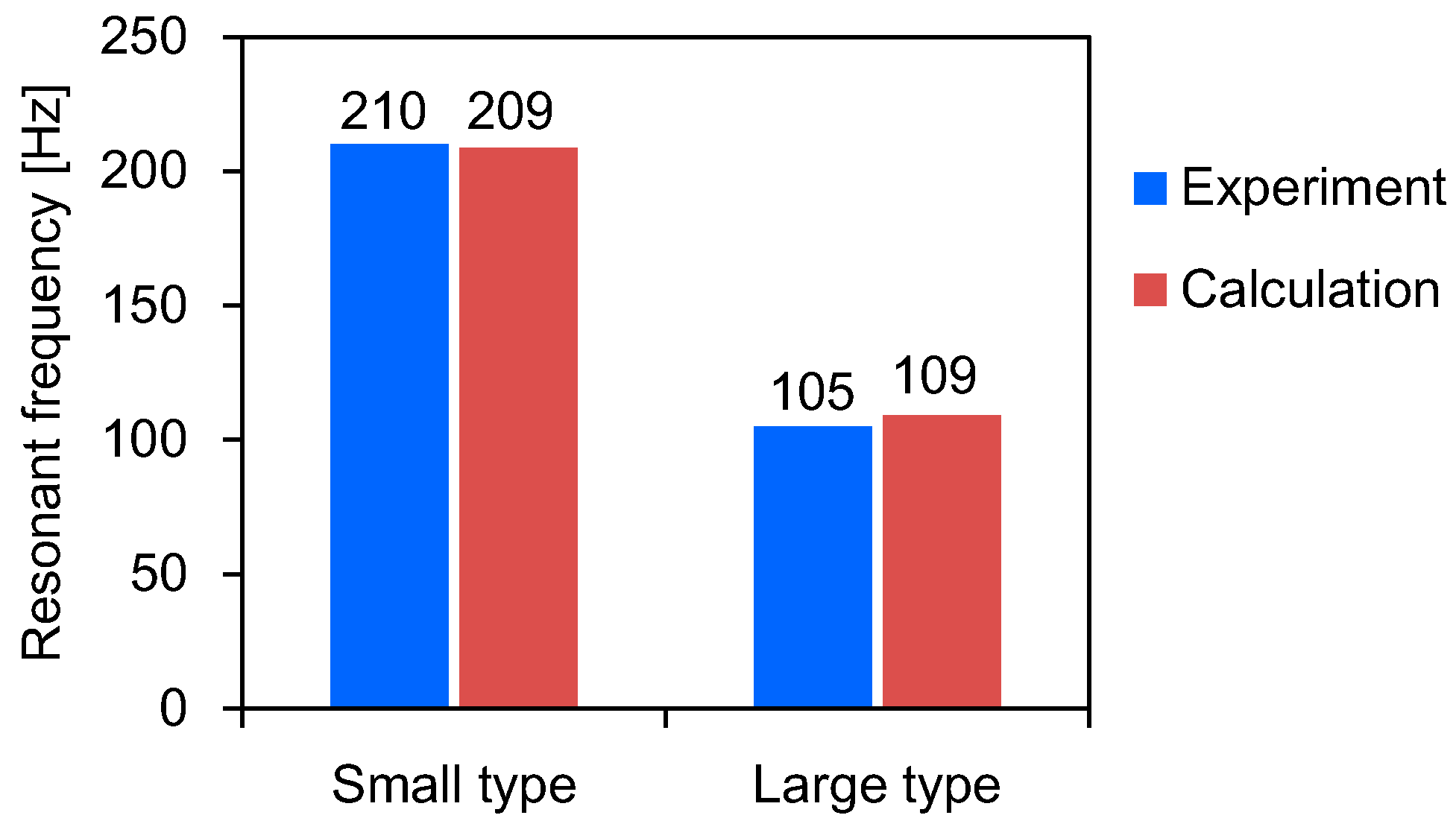
The resonance frequencies were identified by the stroke amplitude response against the frequency-swept input signal in the experiment; we defined the resonant frequency as the frequency with the maximum stroke amplitude. In the calculation, we estimated the resonance frequencies from impulse system responses. The motion equation was solved with an initial condition of at and an impulse input of V. The resonant frequency can be derived by fitting to a function of : , where , , and are parameters that are also estimated in the fitting operation. This method has an advantage of shorter computational time comparing to calculating the response to the frequency-swept input. Figure 9 shows the calculated impulse responses and their fitted curves.
Figure 10 shows a comparison of the measured and calculated results. Blue and red bars show the measured and calculated data, respectively. The measure resonant frequencies of the small and large types were 210 and 105 Hz, respectively. The corresponding calculated resonant frequencies were 209 and 109 Hz. The small type showed roughly two times higher resonance frequency than the large type. The calculations were in very good agreement with the experiments; the errors of the small and large types were −0.7% and 3.8%, respectively. This result indicates that the kinematic part (inertias and springs) of the system has been modelled accurately.
4.3. Resonant Driving Characteristics
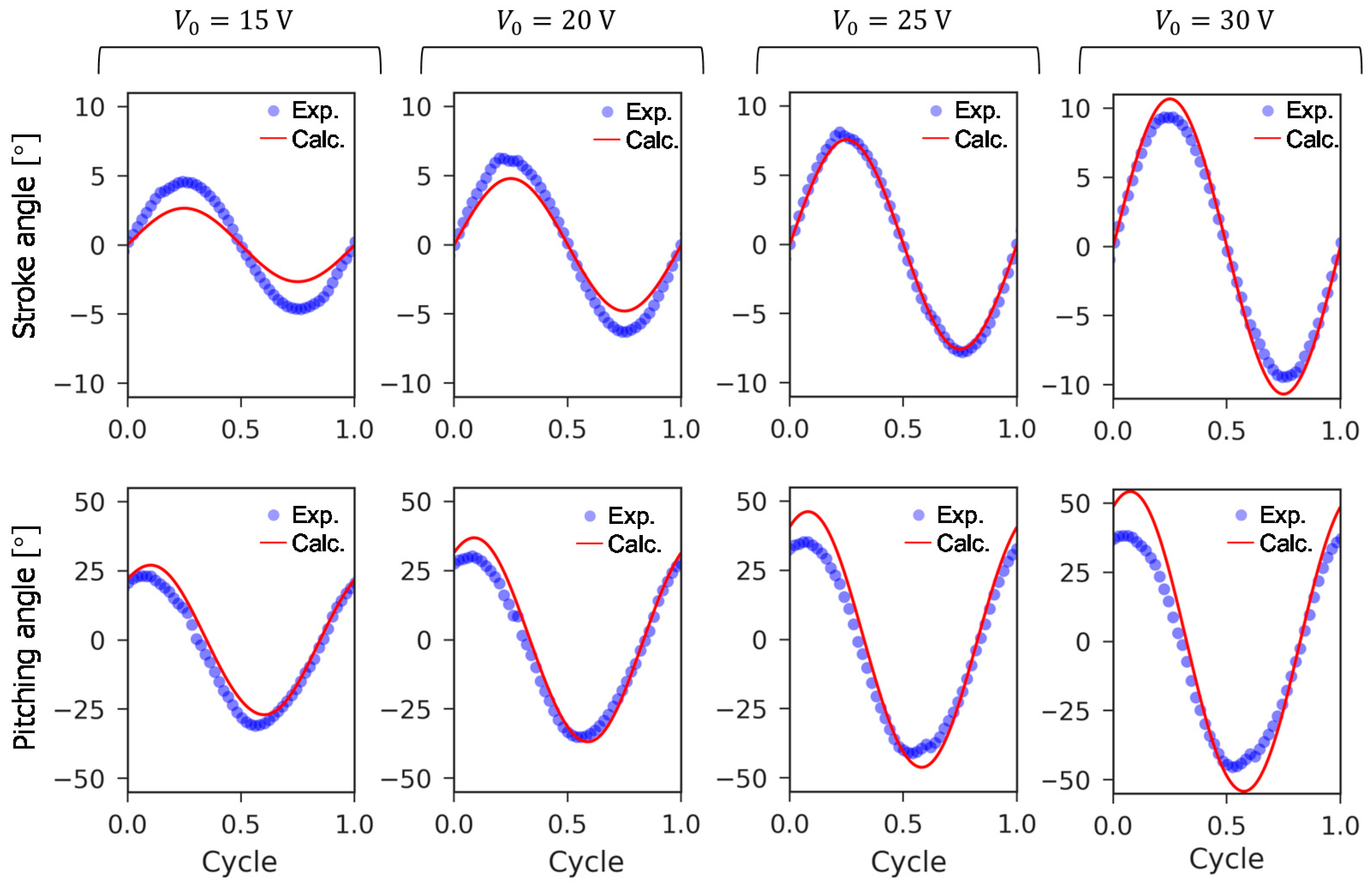
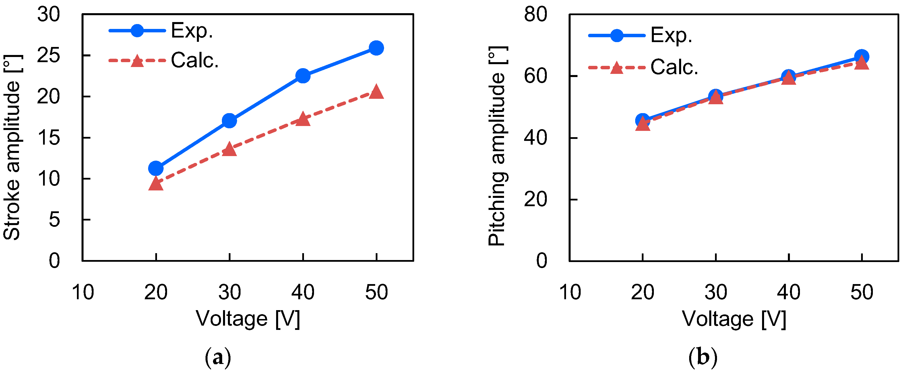
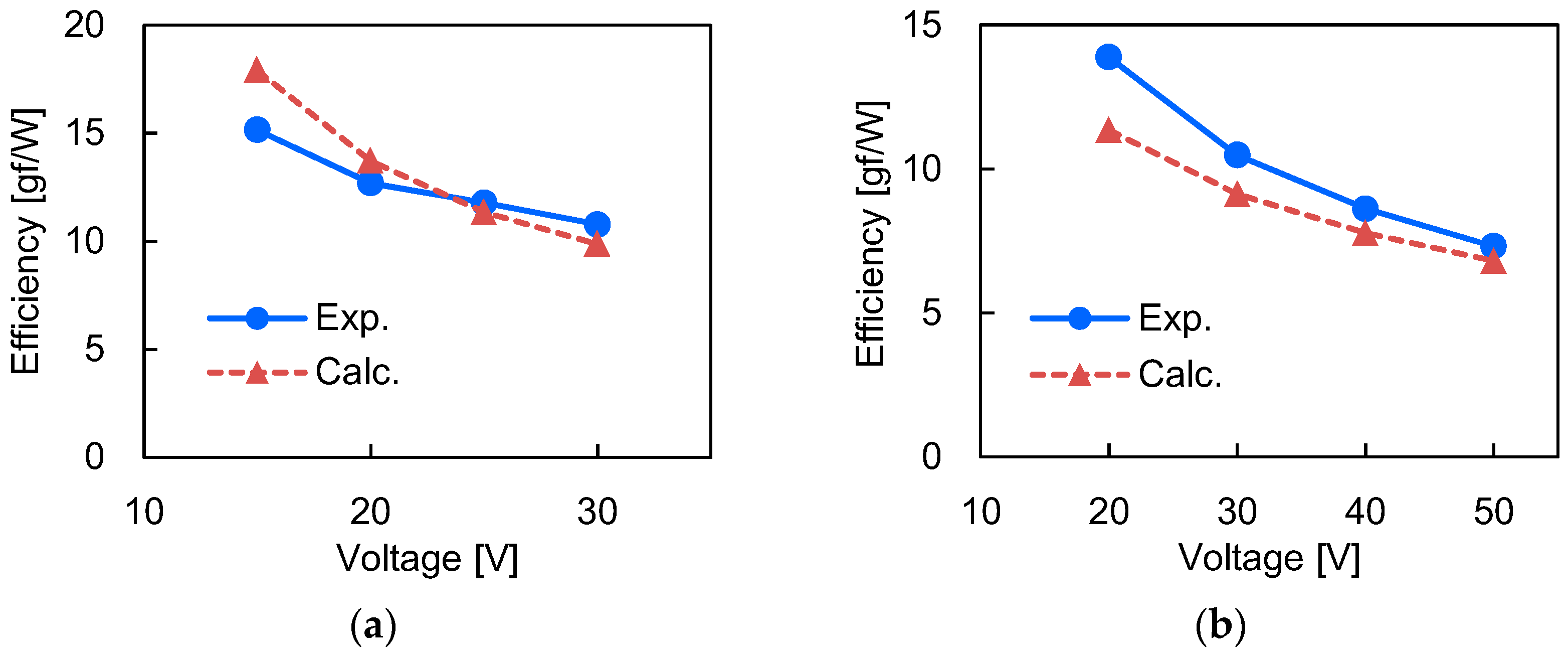
In this experiment, we measured the resonant driving performance of the small- and large-type actuators with of 15–30 and 20–50 V, respectively. Figure 11 and Figure 12 show the motion of the small and large types, respectively. Given the simplicity of the analytical model, we found that the behaviors of the calculated and showed good agreement with the measured data. Figure 13 and Figure 14 show the amplitudes of and . The average absolute errors of and amplitude were 20% and 8.1%, respectively. Figure 15 and Figure 16 show these tendencies of with the lift force and power consumption, respectively. The average absolute errors of the lift force and consumed power between the calculation and the experiment were 15% and 8.7%, respectively. These results suggest that the derived model can well simulate the performances of the flapping-wing actuation system. Figure 17 shows the lift-to-power efficiency of the actuation system; it is defined as the ratio of the lift force to the power consumption. Upon increasing the applied voltage, the efficiency of both types of actuators decreased. The efficiencies of the small and large types at their maximum applied voltages were 10.8 and 7.31 gf/W, respectively.
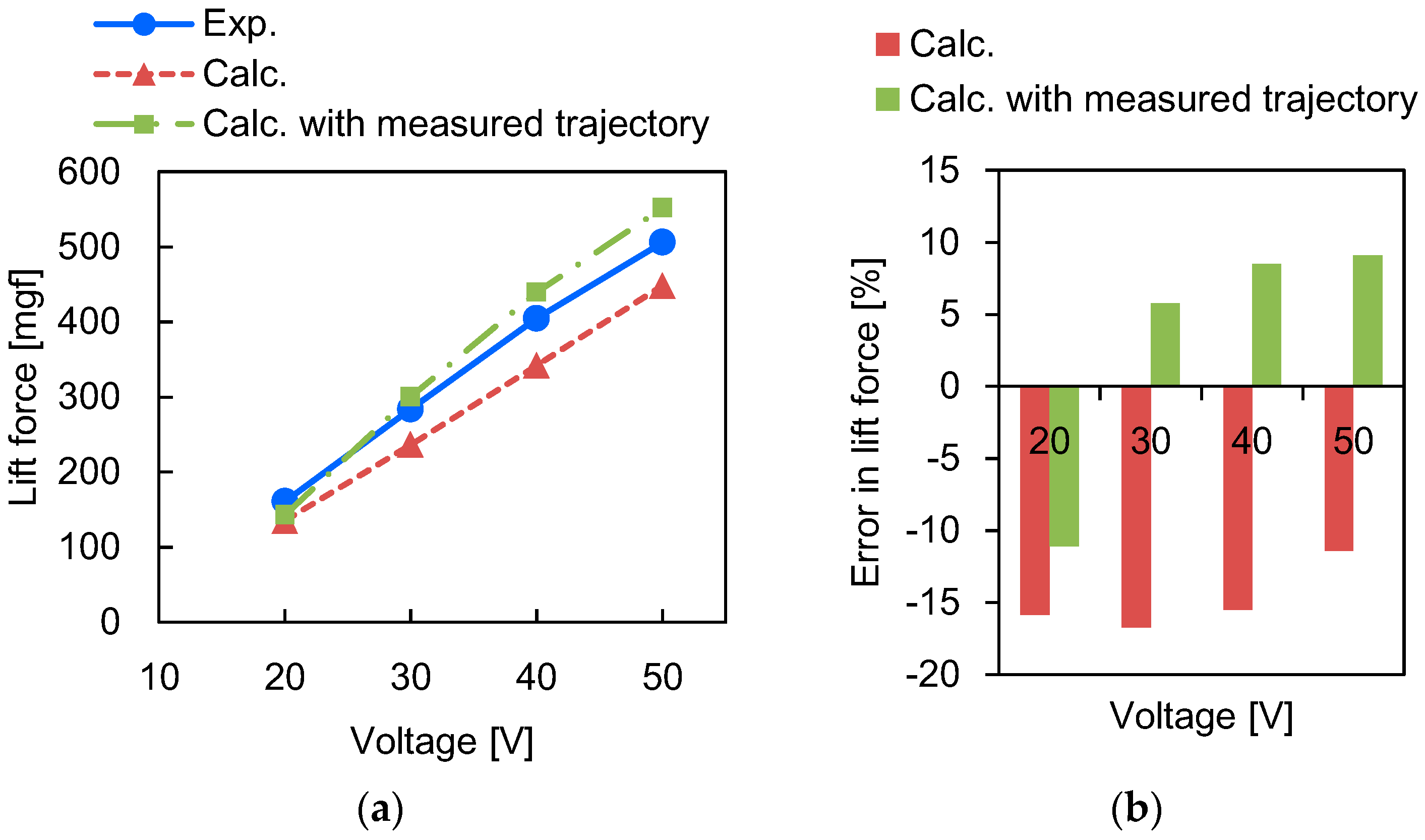
There are two possible causes of lift force error: Wing motion (, ) and analytical model of lift force. As shown in Figure 13 and Figure 14, the predicted and have nonnegligible error. In particular, the trend of the error in showed a similarity to the lift force error. For example, for the small-type actuator, lower resulted in underestimated (calculated was smaller than the measured data) and larger , in overestimated . On the other hand, for the large-type actuator, the calculated was slightly smaller than the measured one for all tested values. The lift forces showed the same trends (Figure 15 and Figure 16). Thus, the error of the lift force was considered to be dominantly caused by the estimation error in the stroke motion. To verify this result, we performed additional calculations in which the lift force was estimated from the measured trajectory of and using Equation (35). The results are shown in Figure 18 and Figure 19; in these figures, we compare the lift forces obtained using the experiment, calculation with the proposed aeromechanic model, and calculation with the prescribed measured trajectories. For both small- and large-type actuators, the lift force obtained from the measured trajectories resulted in smaller errors than that obtained from the fully analytical calculation. This result confirms that the prediction error of the wing motion is the main error source in the lift force estimation. We expect that the accuracy of the wing motion prediction is limited by the imprecision of the aerodynamic drag force and that improving the drag force model is key in the performance analysis of flapping-wing actuators.
5. Conclusions
We modeled a flapping-wing actuation system as a 2-DOF kinematic system with the semi-empirical quasi-steady aerodynamic forces and the electromechanical effect of piezoelectricity. We fabricated actuators of two different scales and measured their performances. The experimental results were in good agreement with the analytical calculations for both types of actuators, and the errors in the evaluated characteristics were less than 30%. We concluded that the analytical model effectively simulates the actual prototypes.
Author Contributions
T.O. conceived and designed the analytical model and experiments; K.H. fabricated the tested samples; T.O. performed the measurements and data analysis and wrote the paper; and K.H. supervised the research.
Conflicts of Interest
The authors declare no conflict of interest.
Appendix A
Table A1 lists the material properties, geometric parameters, and masses/inertias used in the calculation. We derived the masses/inertias and by using 3D CAD. Young’s modulus and the density of the Ti shim plate were determined as 50%, which is the ratio of the slit in the shim plate, of the values of Ti.

Table A1.
Material properties, geometric parameters, and masses/inertias of fabricated actuators.
| Properties | Small Type | Large Type |
|---|---|---|
| (mm) | 17.0 | 32.4 |
| (mm) | 6.51 | 8.34 |
| (mm) | 9.42 | 15.6 |
| (mm) | 2.48 | 2.57 |
| 1.02 | 1.12 | |
| 1.04 | 1.23 | |
| 0.88 | 0.84 | |
| 0.89 | 0.88 | |
| 0.82 | 0.75 | |
| 0.84 | 0.73 | |
| 0.85 | 0.74 | |
| (m−4) | 4.68 × 10⁻¹⁰ | 1.49 × 10⁻⁹ |
| (mg) | 2.31 | 4.09 |
| (kg m2) | 4.81 × 10⁻¹² | 1.03 × 10⁻¹¹ |
| (kg m2) | 5.07 × 10⁻¹¹ | 2.70 × 10⁻¹⁰ |
| (kg m2) | 3.62 × 10⁻¹³ | 7.12 × 10⁻¹² |
| (kg m2) | 3.89 × 10⁻⁹ | 1.47 × 10⁻⁸ |
| (Nm) | 1.48 × 10⁻⁴ | 8.64 × 10⁻⁵ |
| (mm) | 10.5 | 21.0 |
| (mm) | 6.0, 2.4 | 10.4, 4.4 |
| (μm) | 100, 10, 100 | 100, 10, 130 |
| (GPa) | 14.3 *1, 5.0, 50.3 *2 | |
| (kg/m3) | 8000, 1500, 2250 *3 | |
| (pm/V) | 950 *4 | |
| *5 | ||
| (kg/m3) | 1.29 | |
*1 Value was calculated as the reciprocal of the elastic compliance ; *2,3 Values were calculated as 50% of the properties of Ti considering the slit in the Ti shim plate; *4 [011]-poled, direction; *5 is the permittivity of free space.
References
- Wood, R.J. The first takeoff of a biologically inspired at-scale robotics insect. IEEE Trans. Robot. 2008, 24, 341–347. [Google Scholar] [CrossRef]
- Ma, K.Y.; Chirarattananon, P.; Fuller, S.B.; Wood, R.J. Controlled flight of a biologically inspired insect-scale robot. Science 2013, 340, 603–607. [Google Scholar] [CrossRef] [PubMed]
- Chirarattananon, P.; Ma, K.Y.; Wood, R.J. Adaptive control of a millimeter-scale flapping-wing robot. Bioinspir. Biomim. 2014, 9, 025004. [Google Scholar] [CrossRef] [PubMed] [Green Version]
- Whitney, J.P.; Wood, R.J. Aerodynamics of passive rotation in flapping flight. J. Fluid Mech. 2010, 660, 197–220. [Google Scholar] [CrossRef]
- Mateti, K.; Byrne-Dugan, R.A.; Tadigadapa, S.A.; Rahn, C.D. Wing rotation and lift in SUEX flapping wing mechanisms. Smart Mater. Struct. 2013, 22, 014006. [Google Scholar] [CrossRef]
- Dickinson, M.H.; Lehmann, F.-O.; Sane, S.P. Wing rotation and the aerodynamic basis of insect flight. Science 1999, 284, 1954–1960. [Google Scholar] [CrossRef] [PubMed]
- Sane, S.P.; Dickinson, M.H. The aerodynamic effect of wing rotation and a revised quasi-steady model of flapping flight. J. Exp. Biol. 2002, 205, 1087–1096. [Google Scholar] [PubMed]
- Dickson, W.B.; Straw, A.D.; Poelma, C.; Dickinson, M.H. An integrative model of insect flight control. In Proceedings of the AIAA Aerospace Sciences Meeting and Exhibit, Reno, NV, USA, 9–12 January 2006. [Google Scholar]
- Nabawy, M.R.; Crowther, W.J. On the quasi-steady aerodynamics of normal hovering flight part II: Model implementation and evaluation. J. R. Soc. Interface 2014, 11, 20131197. [Google Scholar] [CrossRef] [PubMed]
- Sitti, M.; Campolo, D.; Yan, J.; Fearing, R.S. Development of PZT and PZN-PT based unimorph actuators for micromechanical flapping mechanisms. In Proceedings of the IEEE International Conference on Robotics and Automation, Seoul, Korea, 21–26 May 2001; pp. 3839–3846. [Google Scholar]
- Fearing, R.S.; Chiang, K.H.; Dickinson, M.H.; Pick, D.L.; Sitti, M.; Yan, J. Wing transmission for a micromechanical flying insect. In Proceedings of the IEEE International Conference on Robotics and Automation, San Francisco, CA, USA, 24–28 April 2000; pp. 1509–1516. [Google Scholar]
- Avadhanula, S.; Wood, R.J.; Campolo, D.; Fearing, R.S. Dynamically tuned design of the MFI thorax. In Proceedings of the IEEE International Conference on Robotics and Automation, Washington, DC, USA, 11–15 May 2002; pp. 52–59. [Google Scholar]
- Ma, K.Y. Mechanical Design and Manufacturing of an Insect-Scale Flapping-Wing Robot. Ph.D. Thesis, Harvard University, Cambridge, MA, USA, June 2015. [Google Scholar]
- Finio, B.M.; Pérez-Arancibia, N.O.; Wood, R.J. System identification and linear time-invariant modeling of an insect-sized flapping-wing micro air vehicle. In Proceedings of the IEEE/RSJ International Conference on Intelligent Robots and Systems, San Francisco, CA, USA, 25–30 September 2011; pp. 1107–1114. [Google Scholar]
- Gerdes, J.W.; Bruck, H.; Gupta, S.K. Improving prediction of flapping-wing motion by incorporating actuator constraints with models of aerodynamic loads using in-flight data. J. Mech. Robot. 2017, 9, 021011. [Google Scholar] [CrossRef]
- Gerdes, J.W.; Bruck, H.; Gupta, S.K. Validation of flight power modeling by direct measurement of a flapping wing aerial vehicle. In Proceedings of the AIAA Atmospheric Flight Mechanics Conference, Grapevine, TX, USA, 9–13 January 2017; p. 1632. [Google Scholar]
- Paranjape, A.A.; Chung, S.-J. Optimizing the forces and propulsive efficiency in bird-scale flapping flight. In Proceedings of the AIAA Atmospheric Flight Mechanics Conference, Boston, MA, USA, 19–22 August 2013; Volume 4916. [Google Scholar]
- Whitney, J.P.; Wood, R.J. Conceptual design of flapping-wing micro air vehicles. Bioinspir. Biomim. 2012, 7, 036001. [Google Scholar] [CrossRef] [PubMed]
- Ozaki, T.; Hamaguchi, K. Performance of direct-driven flapping-wing actuator with piezoelectric single-crystal PIN-PMN-PT. J. Micromech. Microeng. 2018, 28, 025007. [Google Scholar] [CrossRef] [Green Version]
- Ozaki, T.; Hamaguchi, K. Bioinspired flapping-wing robot with direct-driven piezoelectric actuation and its takeoff demonstration. Robot. Autom. Lett. 2018, 3, 4217–4224. [Google Scholar] [CrossRef]
- Bronson, J.R.; Pulskamp, J.S.; Rolcawich, R.G.; Kroninger, C.M.; Wetzel, E.D. PZT MEMS actuated flapping wings for insect-inspired robotics. In Proceedings of the IEEE International Conference on Micro Electro Mechanical Systems, Sorrento, Italy, 25–29 January 2009; pp. 1047–1050. [Google Scholar]
- Pulskamp, J.S.; Polcawich, R.G.; Rudy, R.Q.; Bedair, S.S.; Proie, R.M.; Ivanov, T.; Smith, G.L. Piezoelectric PZT MEMS technologies for small-scale robotics and RF applications. MRS Bull. 2012, 37, 1062. [Google Scholar] [CrossRef]
- Brizard, A.J. An Introduction to Lagrangian Mechanics; World Scientific Publishing: Singapore, 2008. [Google Scholar]
- Roundy, S.; Leland, E.S.; Baker, J.; Carleton, E.; Reilly, E.; Lai, E.; Otis, B.; Rabaey, J.M.; Wright, P.K. Improving power output for vibration-based energy scavengers. IEEE Pervasive Comput. 2005, 4, 28–36. [Google Scholar] [CrossRef]
- Ghodssi, R.; Lin, P. MEMS Materials and Processes Handbook; Springer: New York, NY, USA, 2011. [Google Scholar]
- Gere, J.M. Mechanics of Materials, 6th ed.; Thomson Learning, Inc.: Belmont, OH, USA, 2004. [Google Scholar]
- Taha, H.E.; Hajj, M.R.; Beran, P.S. State-space representation of the unsteady aerodynamics of flapping flight. Aerosp. Sci. Technol. 2014, 34, 1–11. [Google Scholar] [CrossRef] [Green Version]
- Munk, M.M. Note on the air forces on a wing caused by pitching. NACA Tech. Notes 1925, 217, 1–6. [Google Scholar]
- Andersen, A.; Pesavento, U.; Wang, Z.J. Unsteady aerodynamics of fluttering and tumbling plates. J. Fluid Mech. 2005, 541, 65–90. [Google Scholar] [CrossRef]
- Erturk, A.; Inman, D.J. A Distributed Parameter Electromechanical Model for Cantilevered Piezoelectric Energy Harvesters. J. Vib. Acoust. 2008, 130, 041002-1. [Google Scholar] [CrossRef]
- Young, W.C. Budynas, R.G. Roark’s Formulas for Stress & Strain, 7th ed.; McGraw-Hill Professional: New York, NY, USA, 2001. [Google Scholar]
Figure 1.
Behavior and structure of flapping-wing actuator with direct-driven mechanism: (a) actuation principle of piezoelectric unimorph actuator and (b) flapping motion of actuation system.
Figure 1.
Behavior and structure of flapping-wing actuator with direct-driven mechanism: (a) actuation principle of piezoelectric unimorph actuator and (b) flapping motion of actuation system.

Figure 2.
Coordinate systems and dimensions of unimorph actuator and wing.

Figure 3.
Coordinates and dimensional parameters of wing.

Figure 4.
Structure of prototype actuation system: components of (a) wing and (b) unimorph actuator; and (c) assembled system and a close-up image of hinge.
Figure 4.
Structure of prototype actuation system: components of (a) wing and (b) unimorph actuator; and (c) assembled system and a close-up image of hinge.

Figure 5.
Photograph of prototype actuators: (a) small type and (b) large type.

Figure 6.
Setup for wing motion, lift force, and power consumption measurement.

Figure 7.
Stroke and pitching measurement from captured image.

Figure 8.
Estimated center position of wing stroke rotation from captured images: (a) small type with and (b) large type with . Blue solid lines indicate the location of the leading edge and dotted lines, their extensions. The red point indicates the estimated center position.
Figure 8.
Estimated center position of wing stroke rotation from captured images: (a) small type with and (b) large type with . Blue solid lines indicate the location of the leading edge and dotted lines, their extensions. The red point indicates the estimated center position.

Figure 9.
Resonant frequency estimation by impulse response: (a) small type and (b) large type.

Figure 10.
Measured and calculated resonant frequencies.

Figure 11.
Measured and calculated stroke and pitching angle of small-type actuator: blue circle and red line show experimental data and calculated result, respectively.
Figure 11.
Measured and calculated stroke and pitching angle of small-type actuator: blue circle and red line show experimental data and calculated result, respectively.

Figure 12.
Measured and calculated stroke and pitching angle of large-type actuator: blue circle and red line show experimental data and calculated result, respectively.
Figure 12.
Measured and calculated stroke and pitching angle of large-type actuator: blue circle and red line show experimental data and calculated result, respectively.

Figure 13.
Relationship between applied voltage amplitude and (a) stroke amplitude and (b) pitching amplitude of small-type actuator. The frequencies of the input signal in the experiment and calculation were 210 and 209 Hz, respectively.
Figure 13.
Relationship between applied voltage amplitude and (a) stroke amplitude and (b) pitching amplitude of small-type actuator. The frequencies of the input signal in the experiment and calculation were 210 and 209 Hz, respectively.

Figure 14.
Relationship between applied voltage amplitude and (a) stroke amplitude and (b) pitching amplitude of large-type actuator. The frequencies of the input signal in the experiment and calculation were 105 and 109 Hz, respectively.
Figure 14.
Relationship between applied voltage amplitude and (a) stroke amplitude and (b) pitching amplitude of large-type actuator. The frequencies of the input signal in the experiment and calculation were 105 and 109 Hz, respectively.

Figure 15.
Relationship between applied voltage amplitude and (a) lift force and (b) consumed power of small-type actuator. The frequencies of the input signal in the experiment and calculation were 210 and 209 Hz, respectively.
Figure 15.
Relationship between applied voltage amplitude and (a) lift force and (b) consumed power of small-type actuator. The frequencies of the input signal in the experiment and calculation were 210 and 209 Hz, respectively.

Figure 16.
Relationship between applied voltage amplitude and (a) lift force; (b) consumed power of large-type actuator. The frequencies of the input signal in the experiment and calculation were 105 and 109 Hz, respectively.
Figure 16.
Relationship between applied voltage amplitude and (a) lift force; (b) consumed power of large-type actuator. The frequencies of the input signal in the experiment and calculation were 105 and 109 Hz, respectively.

Figure 17.
Relationship between applied voltage amplitude and lift-to-power efficiency: (a) small-type and (b) large-type actuators.
Figure 17.
Relationship between applied voltage amplitude and lift-to-power efficiency: (a) small-type and (b) large-type actuators.

Figure 18.
Comparison between fully analytical calculation and calculation based on measured trajectory of small-type actuator: (a) lift force and (b) error of lift force in experimental result.
Figure 18.
Comparison between fully analytical calculation and calculation based on measured trajectory of small-type actuator: (a) lift force and (b) error of lift force in experimental result.

Figure 19.
Comparison between fully analytical calculation and calculation based on measured trajectory of large-type actuator: (a) lift force and (b) error of lift force in experimental result.
Figure 19.
Comparison between fully analytical calculation and calculation based on measured trajectory of large-type actuator: (a) lift force and (b) error of lift force in experimental result.

© 2018 by the authors. Licensee MDPI, Basel, Switzerland. This article is an open access article distributed under the terms and conditions of the Creative Commons Attribution (CC BY) license (http://creativecommons.org/licenses/by/4.0/).
Share and Cite
MDPI and ACS Style
Ozaki, T.; Hamaguchi, K. Electro-Aero-Mechanical Model of Piezoelectric Direct-Driven Flapping-Wing Actuator. Appl. Sci. 2018, 8, 1699. https://0-doi-org.brum.beds.ac.uk/10.3390/app8091699
AMA Style
Ozaki T, Hamaguchi K. Electro-Aero-Mechanical Model of Piezoelectric Direct-Driven Flapping-Wing Actuator. Applied Sciences. 2018; 8(9):1699. https://0-doi-org.brum.beds.ac.uk/10.3390/app8091699
Chicago/Turabian StyleOzaki, Takashi, and Kanae Hamaguchi. 2018. "Electro-Aero-Mechanical Model of Piezoelectric Direct-Driven Flapping-Wing Actuator" Applied Sciences 8, no. 9: 1699. https://0-doi-org.brum.beds.ac.uk/10.3390/app8091699
Note that from the first issue of 2016, this journal uses article numbers instead of page numbers. See further details here.