Design and Research of Double-Sided Linear Switched Reluctance Generator for Wave Energy Conversion

1
College of Electrical and Power Engineering, Taiyuan University of Technology, Taiyuan 030024, China
2
Taiyuan Power Supply Section of China Railway Taiyuan Bureau Group Co., Ltd., Taiyuan 030013, China
*
Author to whom correspondence should be addressed.
Appl. Sci. 2018, 8(9), 1700; https://0-doi-org.brum.beds.ac.uk/10.3390/app8091700
Submission received: 5 August 2018
/
Revised: 7 September 2018
/
Accepted: 17 September 2018
/
Published: 19 September 2018
(This article belongs to the Section Energy Science and Technology)
Abstract
:As a clean and renewable energy source, wave energy is of great significance in solving primary energy shortages and environmental pollution. Direct-drive wave power systems consisting of linear generators have attracted the attention of researchers from various countries. Linear Switched Reluctance Generator has the advantages of simple structure, sturdiness, reliable operation, suitable for harsh environments, and easy maintenance, aiming at the problem of single-sided magnetic pull force and serious coupling of phase winding of traditional linear switched reluctance generator, a Double-sided Linear Switched Reluctance Generator (DLSRG) for wave power generation is designed, and its electromagnetic characteristics (including coupling characteristics, magnetic saturation characteristics, and magnetic tension characteristics) are analyzed to verify the rationality of the structure and parameter selection. Finally, the power generation performance is studied. The joint simulation results show that the structure design of DLSRG is reasonable, overcomes the problem of single-sided magnetic pull force, the phase-to-phase coupling is negligible, and it has continuous power generation capability, and the power generation efficiency is as high as 80.6%. Therefore, DLSRG designed in this paper is suitable for wave power generation.
1. Introduction
With the exhaustion of primary energy, there is a serious environmental pollution and energy shortage in the world. Wave power is one of the richest and promising sources of renewable energy for the future, so it is of great significance to study wave power generation to solve the problem of energy shortage.
In the past four decades, hundreds of Wave Energy Converters (WEC) have been proposed and studied, but so far a conclusive architecture to harvest wave power has not been identified. At present, according to the wave energy-mechanical energy conversion method, the conventional wave energy power generation technology can be divided into three categories: oscillating water column type power generation [1], contraction channel type power generation [2], and hydraulic wave power generation technology [3,4,5].
In the early wave power generation system, rotating generators were used as energy converters. The reciprocating wave energy was converted into mechanical energy and then converted into electrical energy because of the need for intermediate conversion devices, such as cylinders, gears, etc. Its structure was complex and difficult to maintain. The efficiency is relatively low [6]. The direct drive wave power generation system consisting of a linear generator eliminates the intermediate conversion device and it has the advantages of simple structure and easy maintenance.
In recent years, direct-drive generators have been paid more and more attention by researchers all over the world, there are many types of linear generator including transverse flux linear generator [7], linear synchronous generator [8], permanent magnet linear generator [9] and linear switched reluctance generator [10], etc., especially linear permanent magnet generators have been systematically studied [7]. Linear permanent magnet generators have stable power generation and high output efficiency. However, the price of permanent magnets is high and it is difficult to adapt to the harsh working environment [11,12], which hinders its universal application to some extent.
The stator structure of linear switched reluctance generator is simple and strong, and each phase can be controlled independently [13]. It has the advantages of no wear, no lubrication, low speed operation, and so on [14].When compared with the linear permanent magnet generator, the stator of the linear switched reluctance generator is composed of silicon steel laminated, it does not need to install permanent magnet, it is less affected by the external environment, and it can operate under the bad environment, such as high temperature, high corrosion, and other adverse environments, which is more suitable for ocean wave power generation. In the reference [15,16], the single-sided linear switched reluctance generator system is studied; the mutual inductance coupling linear switched reluctance generator has been studied in the reference [11] to improve the efficiency of power generation; Double-sided Linear Switched Reluctance Generator (DLSRG)is studied in the reference [17], which is used to improve the unilateral magnetic tension problem; in the reference [12]; and the optimal efficiency tracking control of generator is studied in detail, and the two-sided mutual inductance coupled switched reluctance generator is chosen as the object of study, which improves the influence of two-sided magnetic pull force.
The purpose of this paper is to design a DLSRG based on improving the single-sided magnetic tension of the traditional single-sided linear switched reluctance generator and reducing the coupling characteristics of the phase winding, the structure of the motor is optimized, the electromagnetic characteristics and generation performance are studied.
This paper is organized as follows: after the introduction, in Section 2 the basic structure and operation principle of DLSRG are given, in Section 3 Mathematical modeling is given, in Section 4 the electromagnetic characteristics of DLSRG is analyzed, in Section 5 the power generation simulation experiment along with the simulation experiment results are presented, and finally, in Section 6, the conclusions are drawn.
2. The Basic Structure and Operation Principle of DLSRG
2.1. Basic Structure
The structure of DLSRG has the advantages of simple structure, easy opening of die, winding by suit, and low requirement for installation and maintenance, and DLSRG operates independently, and the mutual inductance between phase and phase is relatively small, which can be ignored, so the difficulty of control is greatly reduced.
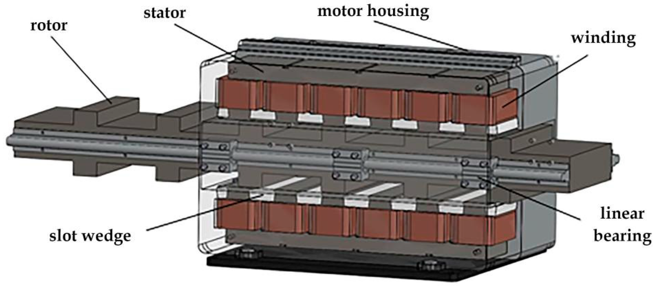
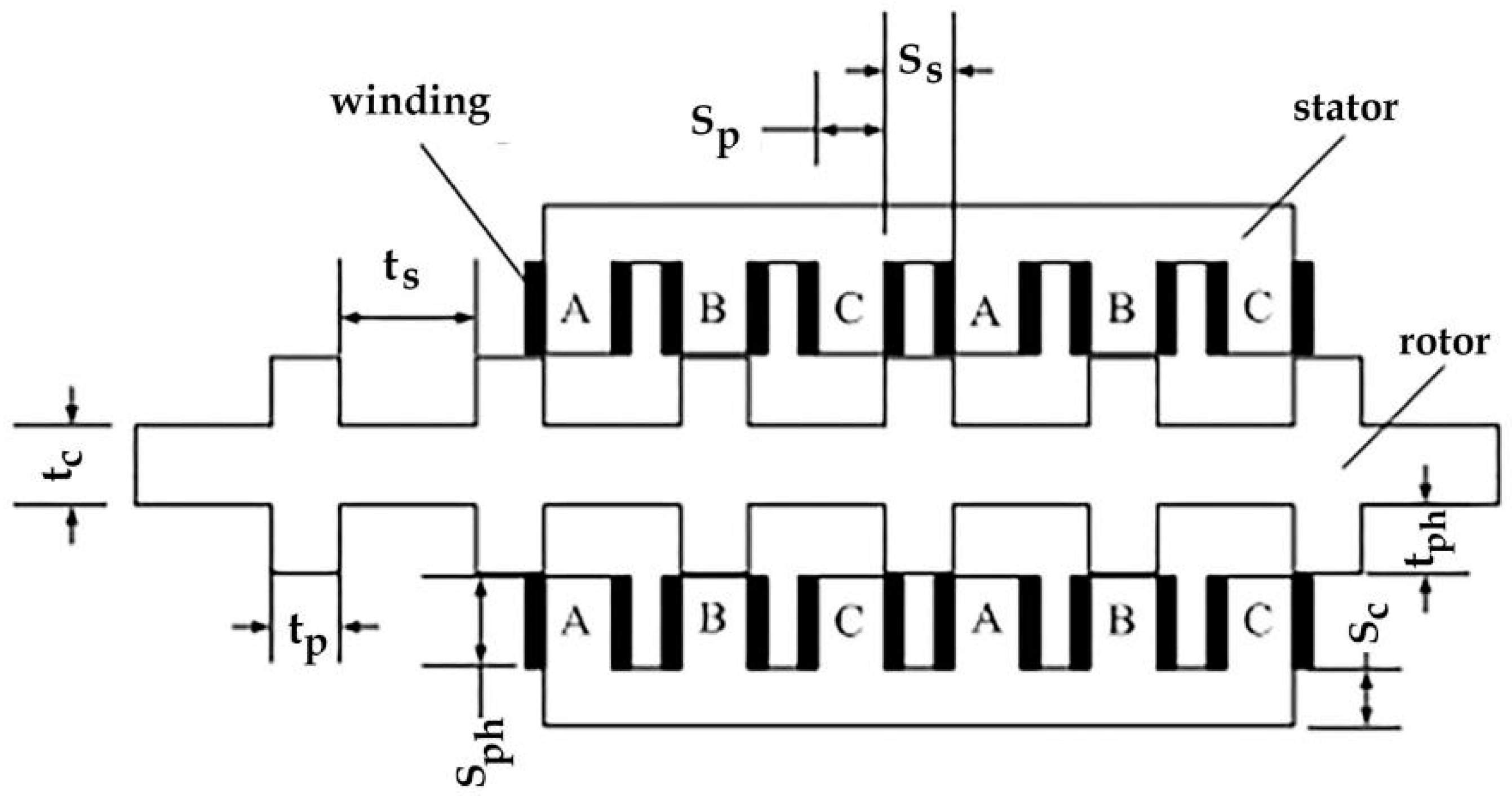
The basic structure of DLSRG is shown in Figure 1. The generator has been preliminarily designed following the approach presented in the reference [18]. The optimization has been performed by letting some geometrical parameters be varied in order to achieve maximum transverse magnetic pull and ensure self-generation capability. The stator and the rotor are made of silicon steel sheet (DW465-50), which is thick in 0.5 mm and has a stacking coefficient of 0.9. The excitation windings are arranged on the stator teeth in turn and are fixed by epoxy resin slot wedge. The precision of slot wedge thickness is low, which is easy to fix and install. The stator slot adopts open slot, which requires lower precision of slot wedge thickness, this kind of structure is easy to fix and install. The rotor is fixed on the shell of generator through linear bearing and base, so reciprocating motion can be realized. The DLSRG cross-section diagram is shown in Figure 2. The letter A, B, C represents the three-phase winding, and the three-phase winding adopts the centralized winding. According to the symmetrical structure, each phase winding is divided into two groups and four coils, and the magnetic loop is formed through the excitation. The three-phase excitation is different from the traditional three-phase excitation. Traditional three-phase excitation, phase difference is 120 degrees. In DLSRG winding, the three phase excitation is equal, the phase difference is 0, the structural parameters of DLSRG are shown in Table 1.
2.2. Operation Principle
The operation of DLSRG follows the principle of magneto resistive minimization [19,20,21]. When the DLSRG is running, the inductance is inversely proportional to the reluctance. When the rotor tooth is aligned with the center line of the stator tooth, the inductance of the phase winding reaches the maximum value and the reluctance is the smallest. When the rotor tooth is separated from the center line of the stator tooth by one tooth width, the phase winding inductance reaches the minimum value, and the magnetoresistance reaches the maximum. When running in a single cycle, it is divided into excitation stage and power generation stage. In the excitation stage, the magnetic pull force is in the same direction as the external mechanical force, and the magnetic field energy is stored; in the power generation stage, the magnetic pulling force is opposite to the external mechanical force, which overcomes the work done by the external mechanical force, changes the external mechanical energy into electric energy, and also releases the stored magnetic field energy.
3. Mathematical Modeling
The first cycle of DLSRG operation is divided into two stages, excitation stage and generation stage. There is essential difference between DLSRG and traditional generator. DLSRG operates independently in three-phase operation process. Its electromagnetic force equation is as follows:
where ik is the phase current of phase k; Lk is the self inductance coefficient of the k phase of the generator. This equation shows that the electromagnetic force is related to the square of the current and the rate of change of the self-inductance. When dLk/dx > 0, the transverse magnetic pull force is in the same direction as the external mechanical force, and the generator is in the excitation stage, when dLk/dx < 0, the transverse magnetic pull force is opposite to the external mechanical force, and the generator is in the generation stage.
The k phase total flux equation of generator is:
where Lk is the k phase inductor; ik is the phase current of phase k. This equation shows that the total flux of phase k is proportional to the inductance of phase k and the current of phase k.
The k phase terminal voltage equation of generator is as follows:
Among them, Rk and ik are generator phase k resistance and current; Ψk is the total flux of k phase of generator. This equation states that the k phase terminal voltage consists of two parts, one part consists of the voltage on the resistance of phase k, the other is the voltage generated by the rate of change of the total flux of phase k.
According to the structure and operation characteristics of DLSRG, when the DLSRG is placed vertically, the normal force on the DLSRG actuator is basically zero, and the effect on the generator operation can be neglected in case of neglecting magnetic flux leakage. Therefore, the friction force can be neglected when considering the motion equation of the rotor. The motion equation of the generator rotor is as follows:
where F is the input of mechanical force, m is the mass of the rotor, x is the displacement of the rotor, t is the moving time of the rotor, and f is the electromagnetic force of the generator. When the generator is in the excitation stage, f is in the same direction as the external mechanical force and when the generator enters the generation stage, f is opposite to the external mechanical force.
To sum up, the mathematical model of DLSRG is represented by the following equations:
The three formulas in Equation (5) have been explained in the above article.
4. Analysis of Electromagnetic Characteristics of DLSRG
In the transient field, the moving speed of the rotor is 1 m/s, the simulation time is 66 ms and the simulation step is 2 ms. The electromagnetic characteristics of DLSRG are analyzed.
4.1. Analysis of Inductance Characteristics
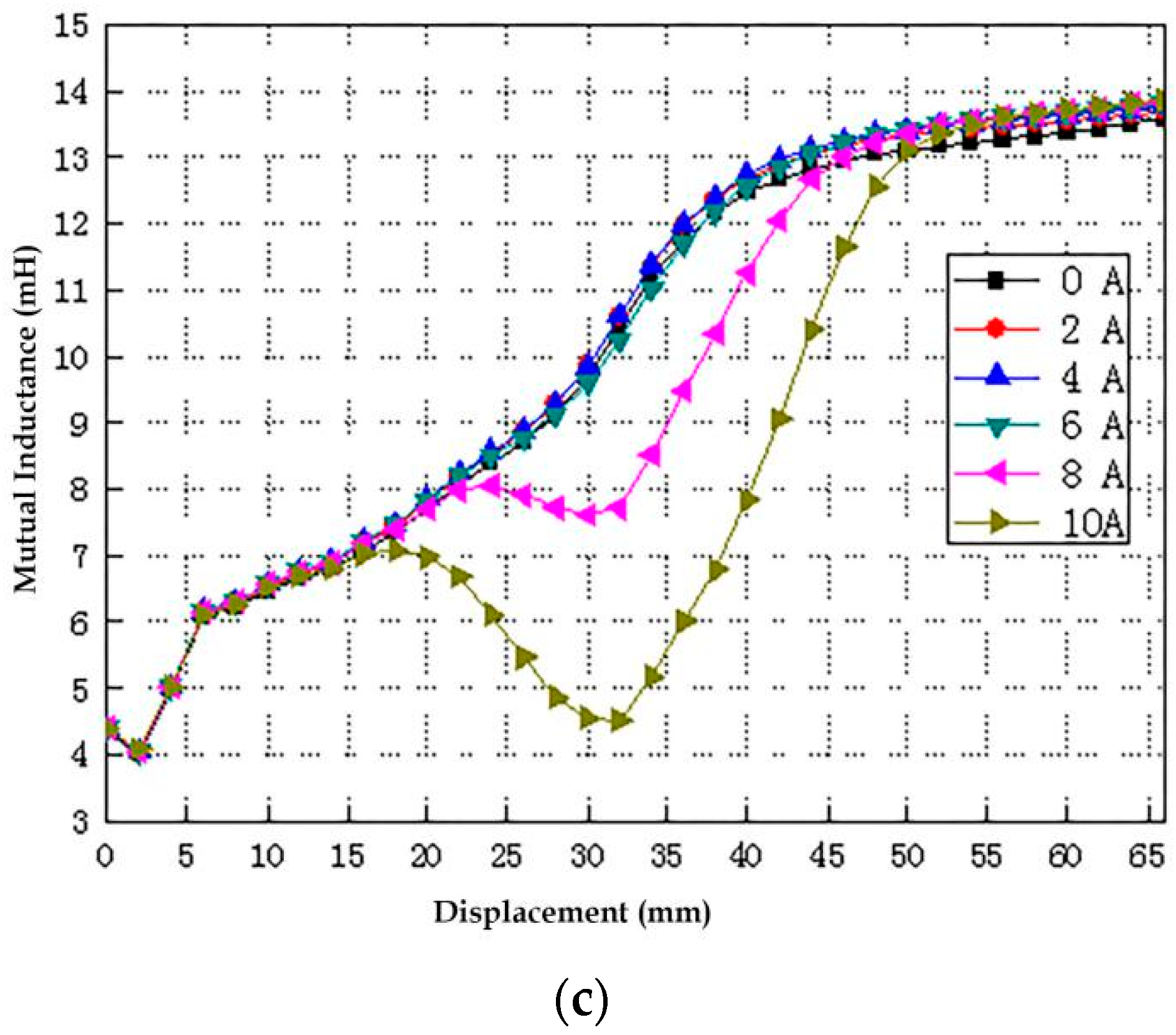
Taking the A phase winding as an example, the current is 0 A, 2 A, 4 A, 6 A, 8 A, 10 A, winding inductance and mutual inductance are shown in Figure 3. Figure 3a is a phase A inductance waveform, Figure 3b,c is the mutual inductance of A phase winding to B phase winding and A phase winding to C phase winding, the mutual inductance of phase A winding to that of phase B winding is about 1.85~8%, and the mutual inductance of phase A winding is about 0.67~4.4% of that of phase A winding. From the above calculated values, it can be seen that the proportion of mutual inductance to inductance is very small and can be ignored [22,23].
4.2. Analysis of Magnetic Saturation
The magnetic density distribution clouds of the typical position of the A phase winding running at a typical position for one cycle with 10 A excitation current are shown in Figure 4. During the operation of the generator, the magnetic density of the stator yoke is always higher than that of the tooth, and the maximum magnetic density of the generator stator tooth alignment with the center line of the motor tooth is about 17475 GS [24], which is lower than the saturation magnetic density of the silicon steel sheet. The magnetic density of excitation stage and generation stage is lower than that of saturation magnetic density, which can be regarded as a linear model, so DLSRG meets the design requirements of magnetic saturation.
4.3. Analysis of Magnetic Pulling Force
In a generation cycle, the position of the right pole tip of the follower tooth aligned with the left pole tip of the stator tooth, and the alignment position between the center line of the actuator tooth and the center line of the stator tooth is called the excitation stage, and the transverse magnetic pull force of the actuator is the same as the direction of the external mechanical force. In this process, the generator stores the magnetic field. The position of the center line of the actuator tooth aligned with the center line of the stator tooth to the position of the left pole tip of the stator tooth and the right pole tip of the stator tooth is called the power generation stage, and the transverse magnetic pull of the actuator is opposite to the direction of the external mechanical force. Transverse magnetic pull overcomes the work done by external mechanical force. The greater the transverse magnetic pull is, the more work is done to overcome the external mechanical force, thus the efficiency of generator generation can be improved. Therefore, in the process of DLSRG running, the transverse magnetic pull force is as large as possible, and the tangential transverse magnetic pull force changes with the current, as shown in Figure 5, and the transverse magnetic tension force increases with the increase of the current. Therefore, the transverse magnetic tension can be increased by increasing the excitation current properly, and then the generation efficiency can be improved.
During the operation of DLSRG, two magnetic pull forces at a certain angle with the moving direction of the actuator are applied to the actuator, which are decomposed into transverse and radial directions. Without considering magnetic flux leakage, the two-sided structure is symmetrical and the radial magnetic pull force is zero. However, in practice, with the change of the relative position of the rotor and stator, there will be asymmetric magnetic leakage in the air gap. The radial magnetic pull produces fluctuations, and the simulation waveform of the radial magnetic pull is shown in Figure 6. With the increase of excitation current, the amplitude of radial magnetic pull increases exponentially, but the radial magnetic pull pulsation is relatively small, within controllable range. Moreover, the maximum radial magnetic pull force of the actuator is 293 N, the friction coefficient of the linear bearing is 0.002–0.003 and the maximum friction force is 0.879 N. The friction force has little effect on the practical running stability of DLSRG. Therefore, the normal magnetic pull of the DLSRG rotor is negligible.
5. Power Generation Simulation Experiment
Generators are also required to verify continuous generation capacity. Switched reluctance generator is very special and has many influence factors on power generation, such as turn-on and turn-off position, load characteristic, speed source, excitation voltage. In this section, the influence of the above factors on generation performance is studied. The penalty coefficient is introduced to optimize the opening and closing positions.
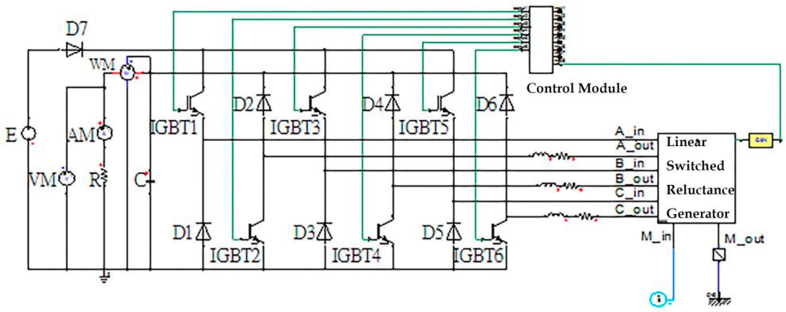
Ansoft Maxwell and Ansoft Simplorer software are used to carry out the joint simulation experiment. The DLSRG joint simulation system, as shown in Figure 7, is mainly composed of excitation power supply, motor module, main circuit and control module. The main circuit adopts asymmetric half-bridge circuit, and the main circuit realizes complete isolation between phase and phase. In the main circuit, six IGBT and six diodes D1~D6 are used as the continuous current diodes, the load end parallels the filter capacitance C and the excitation power supply end series diode to prevent the current backflow. In a generation cycle, it can be regarded as the excitation circuit and the generation circuit. The control unit uses the control module and writes the program in the control module, thus outputs the needed trigger pulse signal.
5.1. Analysis of Influencing Factors
5.1.1. Effect of Turn-Off Position on Phase Current
The turn-off positions are all 49.5 mm. The phase current waveforms at different turn-on positions are shown in Figure 8, and the curve L is a waveform of inductance in generation cycle. It can be seen from the diagram that the phase current is greatly affected by the opening position. When the opening position is 8.5 mm, the phase current is the largest, and the smaller the opening position is, the greater the phase current is. According to the principle of the switched reluctance generator, the generator is in the electric excitation stage when the inductance rises, and the generator converts the electric energy into the mechanical energy and the magnetic field energy. As a result, the greater the current is in an electrically excited state, the more electricity a generator consumes; on the contrary, the smaller the current is in an electrically excited state, the less electricity is consumed. When considering the output efficiency of the generator, the lower the electric excitation consumption is, the higher the efficiency is. When selecting the opening position, the phenomenon of excessive current in the electric excitation stage should be avoided, so the minimum opening position is 18.5 mm.
The turn-on position is 16.5 mm. The phase current waveform at different turn-off positions is shown in Figure 9. The curve L is a waveform of inductance in generation cycle. It can be seen from the diagram that the rising speed of phase current is the same in the rising stage of inductance, that is, the magnitude of turn-off position has no effect on the current of the electric excitation stage, and the change of phase current is obvious in the phase of inductance descending. That is, the turn-off position has a great influence on the current in the generation stage. At the stage of inductance descent, the generator converts mechanical energy and magnetic field energy into electric energy, and the higher the phase current is, the higher the conversion efficiency of generator is. Therefore, the maximum current in the generation stage should be ensured when the turn-off position is selected. It can be seen from the diagram that the phase current in the generation phase increases with the increase of the turn-off position, and the phase current waveform is basically the same when the turn-off position is 47.5 mm and 49.5 mm, that is, the phase current is nearly saturated when the turn-off position is 47.5 mm. With the increasing of the turn-off position, the change of phase current is small, so the turn-off position should be more than 47.5 mm.
5.1.2. Effect of Load on Phase Current
The excitation voltage is 100 V, the moving speed of the rotor is 1 m/s, the simulation time is 100 ms, the simulation step is 2 ms, the open position is 18.5 mm, the turn-off position is 49.5 mm, and the effect of load on phase current is studied. The waveform of phase current under different loads is shown in Figure 10. It can be seen from the diagram that the size of the load has great influence on the phase current at the stage of power generation, when the load value is small (3 Ω), the phase current can continue to rise at the beginning of the generation phase for a period of time. When the load value is larger, the energy consumed by the load is larger (30 Ω), and the phase current will decrease rapidly at the beginning of the generation. Choosing different loads has certain influence on the phase current. For the DLSRG studied in this paper, the load resistance is 10 Ω in the simulation experiment.
5.1.3. Effect of Velocity on Phase Current
Whether the speed of generator rotor is stable or not will seriously affect the stable operation of power generation system. The load R = 10 Ω, excitation voltage U1 is 100 V, simulation time is 100 ms, step size is 2 ms, and the phase current waveform at different speeds is shown in Figure 11. It can be seen from the diagram that the phase current decreases with the increase of velocity. When the speed is too low, the phase current will peak. When the velocity is 0.5 m/s, the current reaches 10 A, and the high peak current will damage the switch. The stable operation of the system is seriously affected, so the phenomenon of too low speed should be avoided when the system is running.
5.1.4. Influence Analysis of Bus Voltage
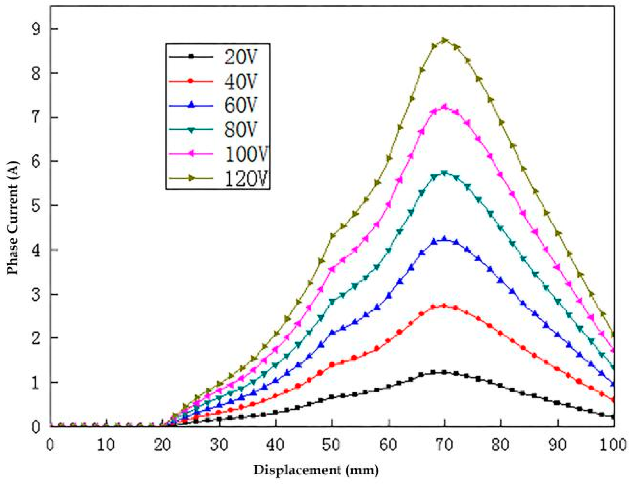
The phase current at different voltage levels is shown in Figure 12. It can be seen from the diagram that when the excitation voltage is half of the rated voltage (50 V), the phase current increases slowly, the amplitude of the phase current is small, and it is difficult to meet the preset requirement, which results in the generator not reaching the preset generation performance. However, the starting current of DLSRG is prevented from being too large when starting, so low voltage can be used to start the DLSRG. When the excitation voltage exceeds the rated voltage, the phase current will quickly exceed the maximum withstanding current of the winding, which will cause great damage to the motor winding, and the peak current will easily damage the switch tube, and at the same time, the core of the motor will reach magnetic saturation. Therefore, when selecting DLSRG excitation power supply, the voltage value should not exceed the rated voltage, but it should not be too low. The excitation voltage is chosen as 100 V in the simulation experiment.
5.2. Optimization of Results
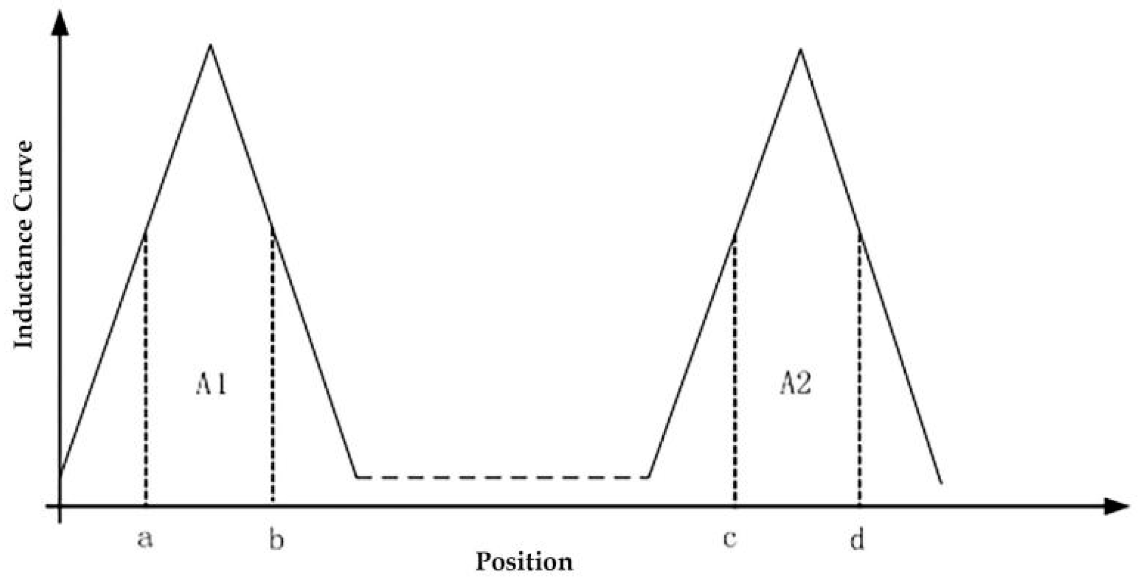
The flow current in the winding can reflect the energy flow of DLSRG in operation, but it can not reflect the effect of turn-on/turn-off position on the efficiency of generator. Therefore, in order to reflect the effect of generation, find out the optimal turn-off position of a group of generators to ensure the maximum generation efficiency. The penalty coefficient, that is, the ratio of excitation current to generation current, can be expressed as:
Iin(av) is the average value of winding phase current in excitation stage and Iout(av) is the average value of generation current between turn-off position and next turn-on position. According to the above formula, the higher the penalty coefficient is, the lower the generation efficiency will be. Therefore, a set of optimal opening and closing positions can be found through the penalty coefficient. The distribution of penalty coefficients is shown in Figure 13.
The penalty coefficient of the load current obtained from the Formula (6) and Figure 13 is as follows:
5.2.1. Open Location Optimization
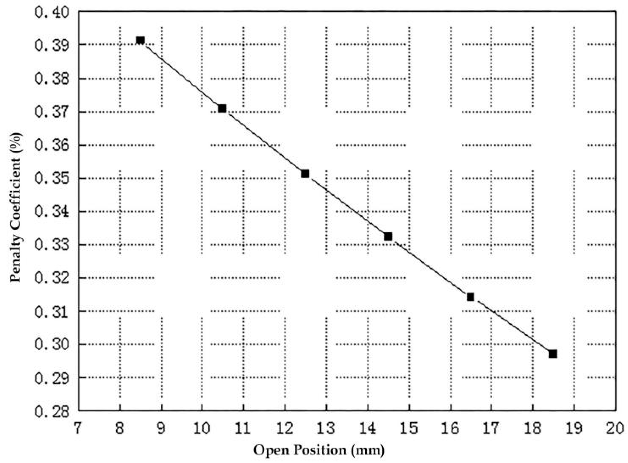
The distribution of the optimal penalty coefficient in the open location is shown in Figure 14. The larger the opening position is, the smaller the penalty coefficient is. When the opening position is 18.5 mm, the penalty coefficient is the smallest. According to the definition of penalty coefficient, the smaller the penalty coefficient is, the better the generation effect is, and the smaller the phase current in the excitation stage is, which ensures that the generation effect and current are within the available range. It is also necessary to ensure the efficiency of mechanical conversion. Therefore, when selecting the opening position, choose x = 18.5 mm as the best opening position.
5.2.2. Turn Off Position Optimization
Penalty coefficients for different turn-off locations are shown in Figure 15. By definition, the smaller the penalty coefficient, the higher the generation efficiency. It can be seen from the diagram that the penalty coefficient is the smallest when the turn-off position is 37.5 mm, and the maximum punishment coefficient is when the turn-off position is 49.5 mm. But when considering the penalty coefficient, the optimal turn-off position is 37.5 mm. However, the mechanical conversion efficiency should also be taken into account when the penalty coefficient is considered. From Figure 9, we can see that the mechanical conversion efficiency is the highest when the turn-off position is 49.5 mm. The final optimal closing position was 49.5 mm.
5.3. Analysis of Simulation Results of Three-Phase Generation
5.3.1. Power Analysis
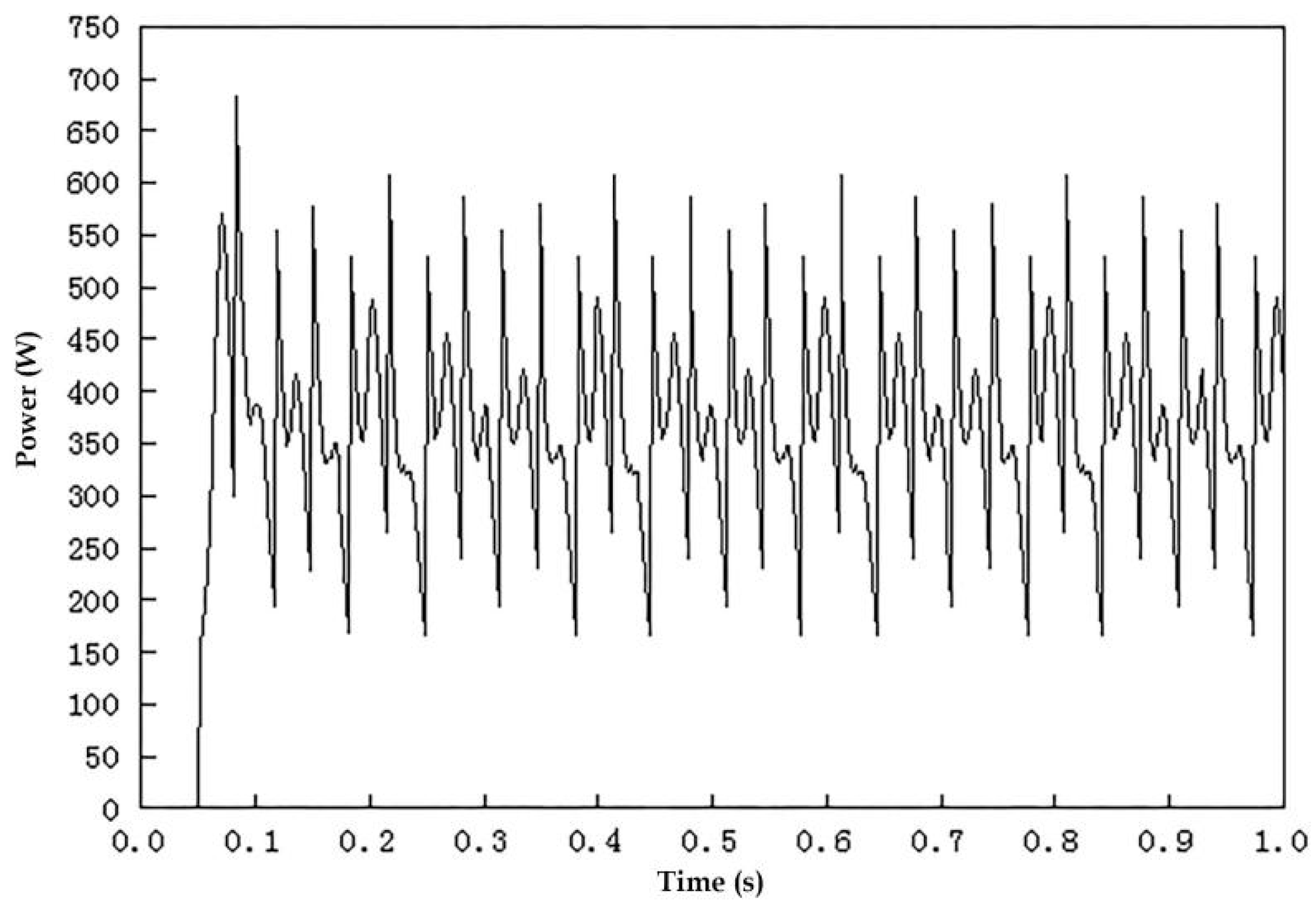
After DLSRG is simulated, the efficiency of DLSRG can be estimated by estimating the energy absorbed in the excitation phase of a generation cycle, the electrical energy output from the generation phase and the mechanical energy input from the outside. If the total electric energy absorbed in the excitation phase is recorded as W1, the total electrical energy output in the generation phase is recorded as W2, and the mechanical energy input from the external input of the generating phase is recorded as W3, the generation efficiency of DLSRG can be expressed, as follows:
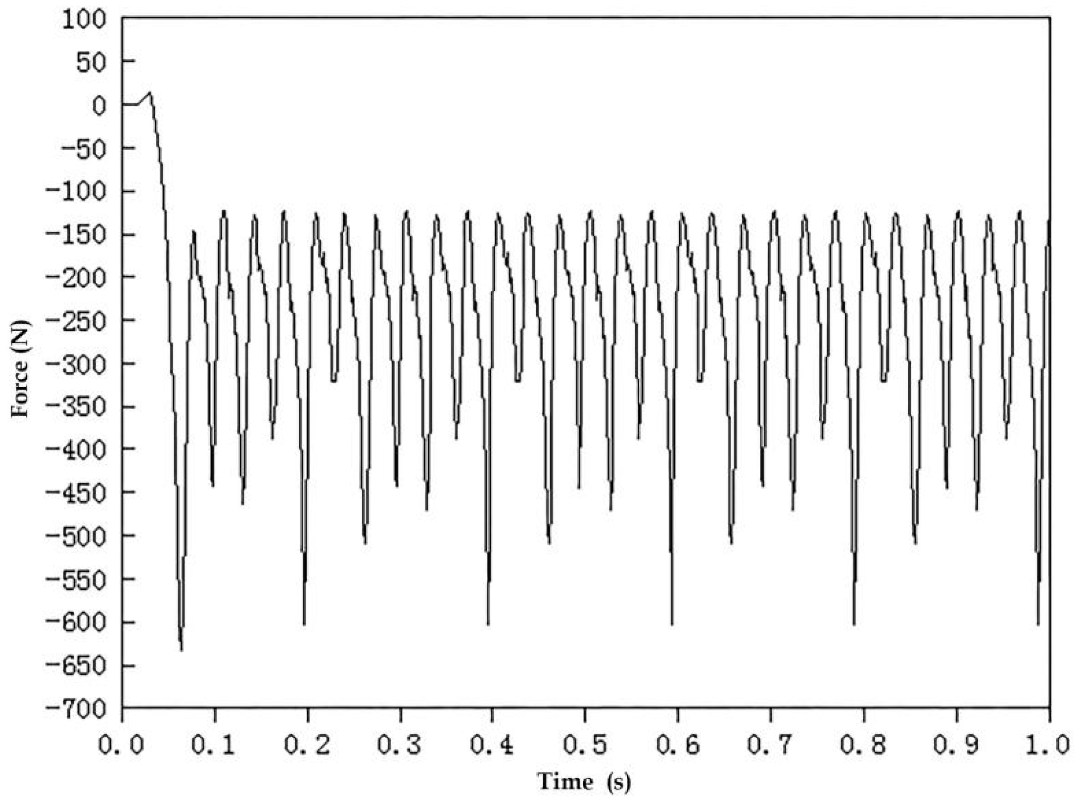
Figure 16 shows the three-phase generation power waveform of DLSRG, Figure 17 shows the excitation power of the DLSRG excitation phase, and Figure 18 shows the force waveform of the generator in the generation phase. According to Formula (8), the electric energy absorbed in the excitation phase, the electric energy emitted during the generation phase, and the mechanical energy absorbed are estimated. Furthermore, the generation efficiency of DLSRG can be estimated. The generation efficiency of DLSRG can be estimated to be about 80.6% by using the equivalent area method.
5.3.2. Generation Voltage Analysis
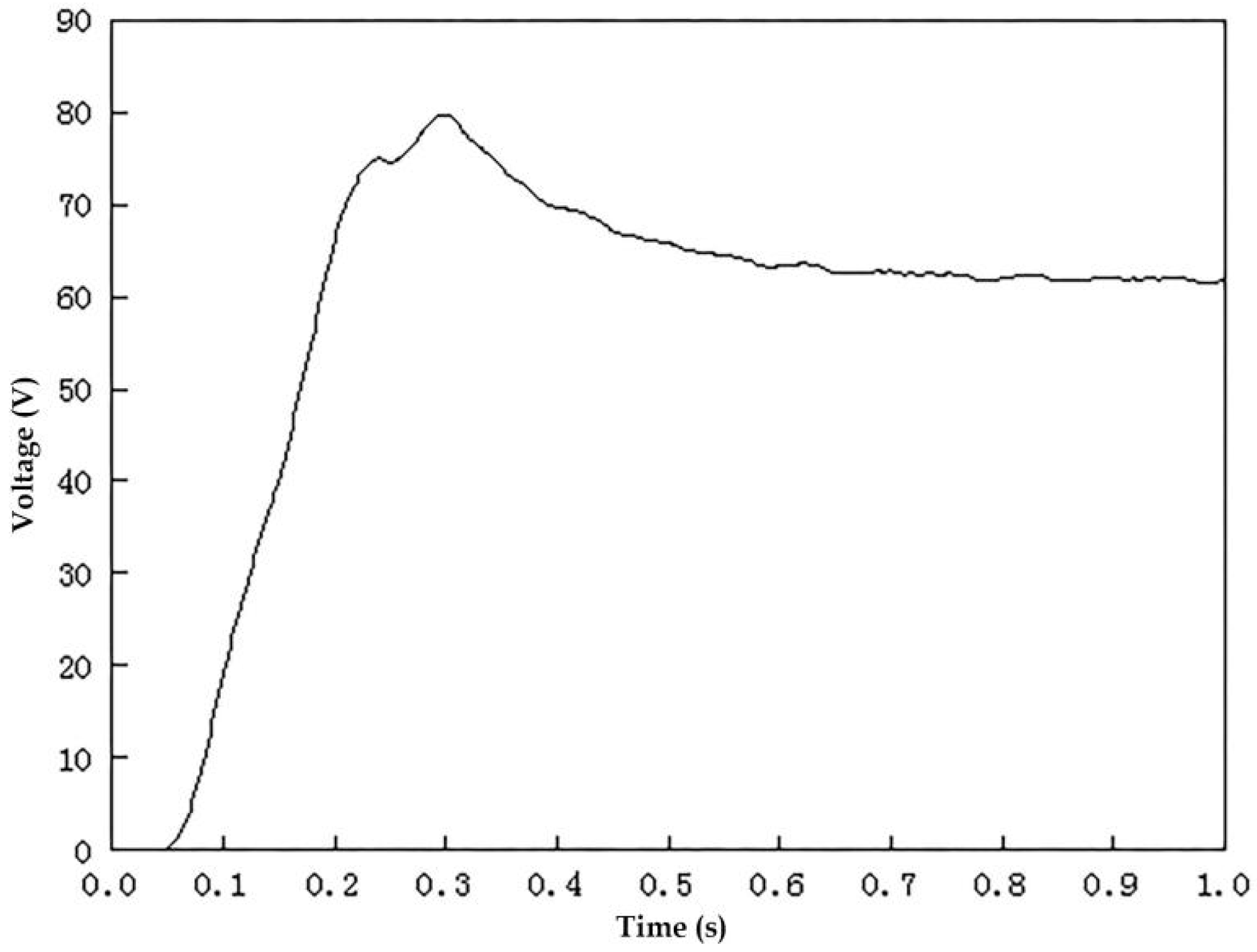
Taking the excitation voltage 100 V and adopting the fixed turn-on turn-off position control method, the optimal turn-on/turn-off position is selected to simulate the three-phase power generation. The generation voltage waveform is shown in Figure 19. It can be seen from the diagram that the generation voltage waveform is large. In order to make the generator output stable, the filtered capacitor of 1800 uF is connected at the load end. The filtered generation voltage waveform is shown in Figure 20. The generation voltage increases rapidly to 80 V at the initial time, and the voltage decreases after 0.3 s due to the addition of filter capacitance. After 0.5 s, the generation voltage is basically stable at 62 V.
6. Conclusions
In this paper, a double-sided linear switched reluctance generator for wave energy conversion is designed. The structure of the generator, the structural dimensions of the stator and the rotor and the package mode of the windings are determined, and the mathematical model of DLSRG is established. The finite element analysis method is used to analyze the electromagnetic characteristics of the bilateral linear switched reluctance generator, and the combined power generation simulation system is established to analyze the power generation characteristics of the bilateral linear switched reluctance generator. The simulation results show that the fluctuation of magnetic pull force is almost zero, the mutual inductance of phase winding accounts for about 0.67% of the inductance of phase winding, which is negligible, and the magnetic field characteristic accords with the design requirement of motor, the filtered generation voltage tends to be stable after 0.5 s, and the stable output of 62 V, the efficiency of generating electricity is as high as 80.6%, and it has the ability to generate electricity continuously, which meets the design requirements. The research work in this paper provides a reference for the research of direct drive wave power generation.
Author Contributions
Conceptualization and writing—original draft: Y.C.; investigation: M.C.; methodology and validation: C.M.; software: Z.F.
Funding
This research is supported by the Natural Science Foundation of Shanxi Province (201701D121127) and by the National Natural Science Foundation Project (41776199).
Acknowledgments
Yinke Dou provided valuable advice on the study idea, design and write-up. Thanks also go to Wentao Wu, Xiangnan Hou, Zaihe Shen, Yanzhao Hao for their assistance during the research.
Conflicts of Interest
The authors declare no conflict of interest. The founding sponsors had no role in the design of the study; in the collection, analyses, or interpretation of data; in the writing of the manuscript, and in the decision to publish the results.
References
- Yang, J.; Xin, Y.; Yang, F. Typical of wave power device and its development trend. Sci. Technol. Innov. Her. 2015, 12, 72–73. [Google Scholar] [CrossRef]
- Yao, Q.; Wang, S.; Hu, H. On the Development and Prospect of Wave Energy Power Generation Device. Ocean Dev. Manag. 2016, 33, 86–92. [Google Scholar] [CrossRef]
- Wang, Z. Design and Research of a New Wave Power Generation Device. Master’s Thesis, Shanghai Jiaotong University, Shanghai, China, 2013. [Google Scholar]
- Cagninei, A.; Raffero, M.; Bracco, G.; Giorcelli, E.; Mattiazzo, G.; Poggi, D. Productivity analysis of the full scale inertial sea wave energy converter prototype: A test case in Pantelleria Island. J. Renew. Sustain. Energy 2015, 7, 397–408. [Google Scholar] [CrossRef]
- Bracco, G.; Giorcelli, E.; Mattiazzo, G. ISWEC: A gyroscopic mechanism for wave power exploitation. Mech. Mach. Theory 2011, 46, 1411–1424. [Google Scholar] [CrossRef]
- Liu, C.; Yu, H.; Hu, M.; Liu, Q.; Chen, Z. Application of permanent magnet linear generator in direct-drive wave power generation system. J. Electron. Eng. China 2013, 21, 90–97. [Google Scholar] [CrossRef]
- Pan, J.F.; Zou, Y.; Cao, G.Z.; Qin, B. Study on the linear switched reluctance generator. Electr. Mach. Control 2013, 17, 39–47. [Google Scholar] [CrossRef]
- Trapanese, M.; Viola, A.; Trapanese, M. Design of a transverse flux machine for power generation from seawaves. J. Appl. Phys. 2014, 115, 4–6. [Google Scholar] [CrossRef]
- Shin, J.-S.; Koseki, T.; Kim, H.-J. Proposal of double-sided transverse flux linear synchronous motor and a simplified design for maximum thrust in nonsaturation region. IEEE Trans. Magn. 2013, 49, 4104–4108. [Google Scholar] [CrossRef]
- Bonanno, A.; Franzitta, V.; Muzio, F.P.; Trapanese, M. A multiphysics approach to the design of a sea wave energy conversion system. In Proceedings of the 2008 IEEE International Conference on Sustainable Energy Technologies, Singapore, 24–27 November 2008. [Google Scholar] [CrossRef]
- Liang, D.; Sui, H.; Du, J.; Zhong, P. Modeling of linear switched reluctance motor’s wave power generation system. J. Mot. Control 2010, 14, 84–88. [Google Scholar] [CrossRef]
- Du, J.; Liang, D. Optimal efficiency tracking control of switched reluctance generator with mutual inductance coupling in wave direct drive. J. Xi’an Jiaotong Univ. 2012, 46, 52–57. [Google Scholar]
- Wang, L.; You, L.; Yue, X. Simulation of switched reluctance motor speed control system based on adaptive fuzzy pid. Electr. Meas. Instrum. 2011, 12, 17–20. [Google Scholar]
- Sun, Y.; Chen, K.; Zhu, Z. Mathematical model of radial force of single winding switched reluctance motor. Electr. Meas. Instrum. 2014, 51, 31–35. [Google Scholar]
- Pu, Y.; Zhou, S.; Gu, J. A novel linear switch reluctance generator system. In Proceedings of the IEEE International Conference on Automation and Logistics, Zhengzhou, China, 15–17 August 2012; pp. 421–427. [Google Scholar] [CrossRef]
- Chen, H.; Wang, X.; Zhou, X.; Peric, N. Switched reluctance variable speed linear generator system. In Proceedings of the International Conference on Electrical Machines and Systems, Beijing, China, 20–23 August 2011; pp. 1–5. [Google Scholar] [CrossRef]
- Chen, H.; Wang, X.; Gu, J.J.; Lu, S. Design of bilateral switched reluctance linear generator. In Proceedings of the Electric Power and Energy Conference, Halifax, NS, Canada, 25–27 August 2011; pp. 1–5. [Google Scholar] [CrossRef]
- Feng, Z.; Ma, C.-Y.; Chen, Y.; Dou, Y.-K.; Yu, G.-H. Design and Finite Element Analysis of a Novel Linear Switched Reluctance Generator. J. North Univ. China (Nat. Sci. Ed.) 2018, 48–53. [Google Scholar] [CrossRef]
- Ma, C.; Wang, Z.; Chen, Y. Kinematic Mechanism and structural design of switched reluctance planar motor. J. Mot. Control 2008, 12, 38–41. [Google Scholar] [CrossRef]
- Li, G.; Ma, C.; Chen, Y. Application of Maxwell 3D in structural design of switched reluctance planar motor. Micromotor 2009, 37, 31–32. [Google Scholar]
- Wu, H. Theory and Control Technology of Switched Reluctance Motor System; China Electric Power Press: Beijing, China, 2010; ISSN 9787512303362. [Google Scholar]
- Li, Q.; Xia, J.; Pan, J.F. Load analysis for the asymmetric bilateral linear switched reluctance generator. In Proceedings of the International Conference on Power Electronics Systems and Applications, Hong Kong, China, 15–17 December 2015; pp. 1–4. [Google Scholar] [CrossRef]
- Ma, Q. Design and Speed Regulation System of Linear Switched Reluctance Motor. Master’s Thesis, Henan University of Technology, Zhengzhou, China, 2009. [Google Scholar]
- Pan, J.F.; Zou, Y.; Cheung, N.C. Design and optimization for the linear switched reluctance generator. In Proceedings of the International Conference on Power Electronics Systems and Applications, Hong Kong, China, 8–10 June 2011; pp. 1–5. [Google Scholar] [CrossRef]
Figure 1.
Basic structure of Double-sided Linear Switched Reluctance Generator (DLSRG). The motor consists of the stator, the rotor, the motor housing, the windings, the slot wedges, the linear bearing.
Figure 1.
Basic structure of Double-sided Linear Switched Reluctance Generator (DLSRG). The motor consists of the stator, the rotor, the motor housing, the windings, the slot wedges, the linear bearing.

Figure 2.
Schematic diagram of DLSRG. The A, B, C represents the three-phase winding. In DLSRG winding, the three phase excitation is equal, the phase difference is 0, the structural parameters of DLSRG are shown in Table 1.
Figure 2.
Schematic diagram of DLSRG. The A, B, C represents the three-phase winding. In DLSRG winding, the three phase excitation is equal, the phase difference is 0, the structural parameters of DLSRG are shown in Table 1.

Figure 3.
When the winding current is 0 A, 2 A, 4 A, 6 A, 8 A, 10 A, winding inductance and mutual inductance are shown in Figure 3. (a) Phase A self-inductance; (b) Phase A-B Mutual Inductance; (c) Phase A-C Mutual Inductance.
Figure 3.
When the winding current is 0 A, 2 A, 4 A, 6 A, 8 A, 10 A, winding inductance and mutual inductance are shown in Figure 3. (a) Phase A self-inductance; (b) Phase A-B Mutual Inductance; (c) Phase A-C Mutual Inductance.


Figure 4.
Magnetic density distribution cloud image of typical position in one cycle operation of DLSRG. (a) The generator is in the excitation phase; (b) The generator is in the critical state; (c) The generator is in the power generation stage.
Figure 4.
Magnetic density distribution cloud image of typical position in one cycle operation of DLSRG. (a) The generator is in the excitation phase; (b) The generator is in the critical state; (c) The generator is in the power generation stage.


Figure 5.
When the winding current is 0 A, 2 A, 4 A, 6 A, 8 A, 10 A, the transverse magnetic pull force changes with current as shown in Figure 5.
Figure 5.
When the winding current is 0 A, 2 A, 4 A, 6 A, 8 A, 10 A, the transverse magnetic pull force changes with current as shown in Figure 5.

Figure 6.
When the winding current is 0 A, 2 A, 4 A, 6 A, 8 A, 10 A, the radial magnetic pull force simulation waveform is shown in Figure 6.
Figure 6.
When the winding current is 0 A, 2 A, 4 A, 6 A, 8 A, 10 A, the radial magnetic pull force simulation waveform is shown in Figure 6.

Figure 7.
The DLSRG joint simulation system is mainly composed of excitation power supply, motor module, main circuit and control module as shown in Figure 7.
Figure 7.
The DLSRG joint simulation system is mainly composed of excitation power supply, motor module, main circuit and control module as shown in Figure 7.

Figure 8.
The turn-off positions are all 49.5 mm. The phase current waveforms at different turn-on positions are shown in Figure 8, it can be seen from the Figure 8 that the phase current is greatly affected by the opening position.

Figure 9.
The turn-on position is 16.5 mm. The phase current waveform at different turn-off positions is shown in Figure 9, it can be seen from the Figure 9 that the turn-off position has a great influence on the current in the generation stage.

Figure 10.
The phase current waveform under different loads is shown in Figure 10. Choosing different loads has certain influence on the phase current.
Figure 10.
The phase current waveform under different loads is shown in Figure 10. Choosing different loads has certain influence on the phase current.

Figure 11.
The phase current waveform at different speeds is shown in Figure 11. When the speed is too low, the phase current will peak.
Figure 11.
The phase current waveform at different speeds is shown in Figure 11. When the speed is too low, the phase current will peak.

Figure 12.
The phase currents at different voltage levels is shown in Figure 12.
Figure 12.
The phase currents at different voltage levels is shown in Figure 12.

Figure 13.
Distribution of penalty coefficient.

Figure 14.
The distribution of the optimal penalty coefficient in the open location is shown in Figure 14. The larger the opening position is, the smaller the penalty coefficient is.
Figure 14.
The distribution of the optimal penalty coefficient in the open location is shown in Figure 14. The larger the opening position is, the smaller the penalty coefficient is.

Figure 15.
The distribution of the optimal penalty coefficient in the turn-off location is shown in Figure 15. The larger the turn-off position is, the larger the penalty coefficient is.
Figure 15.
The distribution of the optimal penalty coefficient in the turn-off location is shown in Figure 15. The larger the turn-off position is, the larger the penalty coefficient is.

Figure 16.
Three-phase Generation Power Waveform of DLSRG.

Figure 17.
Excitation Power in DLSRG excitation stage.

Figure 18.
The force waveform of the rotor in power generation stage.

Figure 19.
When there is no filter capacitor, the power generation voltage waveform is shown in Figure 19.
Figure 19.
When there is no filter capacitor, the power generation voltage waveform is shown in Figure 19.

Figure 20.
The filtered capacitor of 1800 uF is connected at the load end, the filtered generation voltage waveform is shown in Figure 20.
Figure 20.
The filtered capacitor of 1800 uF is connected at the load end, the filtered generation voltage waveform is shown in Figure 20.


Table 1.
DLSRG parameters.
| Parameter | Numerical Value | Parameter | Numerical Value |
|---|---|---|---|
| Statorslot width ss/mm | 33 | Motor body width w/mm | 150 |
| Stator tooth width sp/mm | 33 | air gap g/mm | 1.5 |
| Statortooth height sph/mm | 54 | Stator silicon steel sheet ssi/sheet | 300 |
| Stator yoke sc/mm | 21 | Rotor silicon steel sheet tsi/sheet | 300 |
| Rotor slot width ts/mm | 66 | number of turns of winding N/circle | 273 |
| Rotor tooth width tp/mm | 33 | Enamelled wire diameter d/mm | 1.38 |
| Rotortooth height tph/mm | 19 | Enamelled wire cross section S/mm2 | 1.496 |
| Rotor yoke tc/mm | 48 | Full tank rate Ks | 0.4596 |
© 2018 by the authors. Licensee MDPI, Basel, Switzerland. This article is an open access article distributed under the terms and conditions of the Creative Commons Attribution (CC BY) license (http://creativecommons.org/licenses/by/4.0/).
Share and Cite
MDPI and ACS Style
Chen, Y.; Cao, M.; Ma, C.; Feng, Z. Design and Research of Double-Sided Linear Switched Reluctance Generator for Wave Energy Conversion. Appl. Sci. 2018, 8, 1700. https://0-doi-org.brum.beds.ac.uk/10.3390/app8091700
AMA Style
Chen Y, Cao M, Ma C, Feng Z. Design and Research of Double-Sided Linear Switched Reluctance Generator for Wave Energy Conversion. Applied Sciences. 2018; 8(9):1700. https://0-doi-org.brum.beds.ac.uk/10.3390/app8091700
Chicago/Turabian StyleChen, Yan, Min Cao, Chunyan Ma, and Zhigang Feng. 2018. "Design and Research of Double-Sided Linear Switched Reluctance Generator for Wave Energy Conversion" Applied Sciences 8, no. 9: 1700. https://0-doi-org.brum.beds.ac.uk/10.3390/app8091700
Note that from the first issue of 2016, this journal uses article numbers instead of page numbers. See further details here.