1. Introduction
Remote sensing methods are often the only way to investigate specific archaeological sites (e.g., Reference [
1]). One of them is the muon radiography method for probing sizable solids and constructions, based on the analysis of absorption and scattering of cosmic muon fluxes on their way through the substance of the investigated object.
The first experiment investigating an archaeological site with the help of muons of cosmic origin was the study of the Pyramid of Khafre in Egypt by the group of the Nobel prize winner L. Alvarez [
2,
3]. Recently, a successful attempt to study another archaeological object, the Khufu pyramid, was undertaken by an international team of scientists from Japan, France and Egypt in 2016–2017 within the framework of the ScanPyramids project [
4]. The result of the studies performed with emulsion track detectors was the discovery of a new unknown chamber, which is the first great breakthrough in the Cheops pyramid investigation since the XIXth century, without any damage to the construction. This sensational result, confirmed by the electronic instrumentation, demonstrated the success of the muon radiography method based on emulsion detectors in the study of archaeological objects.
Our experiment was carried out in spring 2018 by collaborators from the National University of Science and Technology Moscow Institute of Steel and Alloys, “MISiS”, Lebedev Physical Institute of RAS, Skobeltsyn Institute of Nuclear Physics of Moscow State University; Institute of History, Archaeology and Ethnography of Dagestan Scientific Centre of RAS, and Dagestan State University, with the participation of the Agency for the Protection of Cultural Heritage of the Republic of Dagestan. The aim was to clarify the possibility of investigating the selected archaeological site by using the muon radiography method, to determine the optimal exposure, number, size and arrangement of the detectors employed and to obtain the first images of the object by nuclear emulsions.
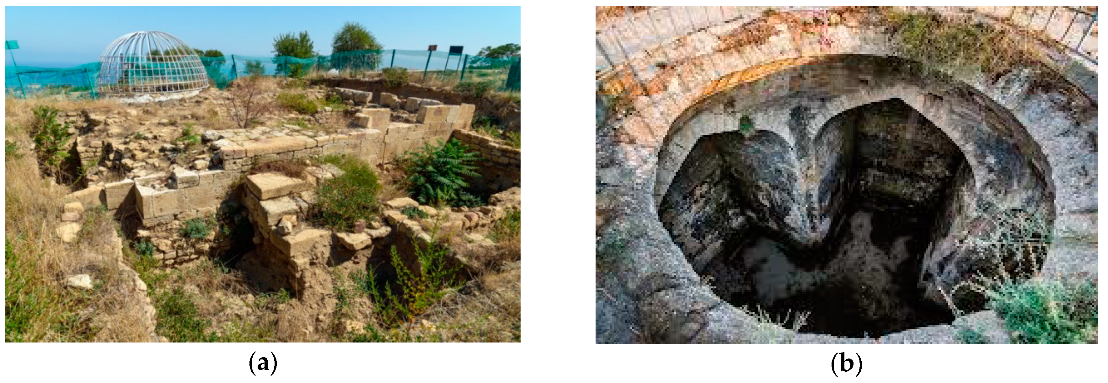
The object of study was an underground cross-shaped dome construction oriented to the cardinal directions, located in the citadel of Naryn-Kala in ancient Derbent. The construction built from local shell-limestone is about 11 meters high and extends for 14.8 m from south to north and 13.4 m from west to east (
Figure 1). The segments (arms) of the cross-shaped construction are about 4.7 m wide, three arms are about 4.2 m long, and the fourth (northern) one is over 6 m long. The arms are covered with ogival vaults, and above the central part a wire frame of the dome 5 m in diameter is located.
In some historical and reference literature this construction is mentioned as an underground reservoir for water, as it was in XVII–XVIII centuries (see, e.g., Reference [
5]). At the same time, it was suggested that this construction was originally an early Christian church established during V–VI A.D, [
6,
7] or a Zoroastrian temple of fire [
8]. The construction is almost completely hidden by a cultural layer; on the modern surface, only a fragment of the half ruined dome and the back end of the northern section (arm) with a window are seen (
Figure 1). Specialists emphasize the need to study this structure by using non-invasive methods (without destruction of the cultural layer) [
9]. Its investigation by traditional methods, such as archaeological excavations, is rather problematic, as nobody knows how the walls of the building exposed to the long-time action of water would behave when released from the ground. Moreover, massive diggings would disturb the existing historical landscape of the citadel and reveal the adjacent architectural complexes of various medieval periods, requiring preservation and conservation. Under such conditions, the method of muon radiography seems to be the only possible approach to study this architectural and archaeological site. The presence of voids, or dense areas in the walls and adjacent soil discovered by this method can confirm one of the hypotheses of its function.
2. The Archaeological Site Probing by Muon Radiography Method
High-energy muons generated in the Earth atmosphere by the cosmic ray particles have a very high penetrability, making them unique agents for probing sizable objects under the earth and on its surface (geological deposits, volcanoes, caves, nuclear reactors, archaeological objects etc.). Even at comparatively limited energy, a muon can pass through the entire atmosphere and penetrate deep into the earth’s crust: cosmic muons with energies of Eµ ~ 1–10 TeV were registered in underground laboratories at depths of about 2 km [
10]. As a result, since the spectrum of atmospheric muons of cosmic origin extends to hundreds of TeV and above, muon fluxes have in their composition high-energy particles that can pass through kilometer-thick objects of high density.
The physical principle of muon radiography is based on two phenomena, the first of which is the attenuation of the muon flux in the absorber owing to electromagnetic processes (ionization, bremsstrahlung radiation, generation of electron–positron pairs). When a substance of another density occurs during a charged particle flux, the intensity of electromagnetic interactions changes and affects the intensity of muon flux absorption in this zone. The other phenomenon is conditioned by multiple Coulomb scattering, when with the increase of the absorber atomic number, the extent of particle scattering increases to lead to a noticeable deviation of the particle trajectory angle from the initial one.
Currently, in experiments conducted using the method of muon radiography, both electronic and emulsion track detectors are used. Emulsion detectors [
11,
12] have a number of advantages, with the main one being a high angular resolution. Of all the muon radiography detectors, the emulsion ones have the best angular resolution. None of the currently known detectors of elementary particles provide a spatial resolution in the way that the nuclear emulsion does: with a grain size of 0.3–1 micron, the grain deviation from the restored trajectory of the particle does not exceed the average value of 0.8 microns, and under certain conditions can reach 0.2 microns. When using natural probing radiation, that is the flux of atmospheric muons, the detector is placed on a side or below the studied object (the so-called one-sided muon radiography [
13]). The number of muons passing through the object depends on material of the object under study and the length of the muon path within it. Muons with a range in the substance greater than their path lengths in the tested object reach the detector. The registered particle tracks, which are chains of developed grains of silver halides ionized by a passing charged particle, allow restoring the spatial trajectory of this particle with accuracy of several milliradians (which means a spatial resolution about 10 m at the distance of 1 km). Each registered muon is characterized by the values of azimuth and zenith angles of its trajectory relative to the axis normal to the detector plane. The angular distributions of muon tracks registered by the detector aimed at the object indicate absorption and scattering features of these probing particles and, therefore, the presence in this area of zones with different material properties. The use of several detectors enables obtaining a 3D tomogram of the internal structure of the object under study. Detailed review of the method and its potential are given in Reference [
14].
Preliminary analysis carried out on topographical maps has shown that muon radiography detectors can be arranged inside the object so that to scan it completely (
Figure 2). Registration of muons in solid angles indicated in
Figure 2 was carried out by track detectors, made of layers of double-sided nuclear emulsion films of 10 × 12.5 cm
2 [
15,
16]. In total, five emulsion detectors were used in this experiment: four wall-oriented detectors, and one directed upwards to measure the vertical muon flux.
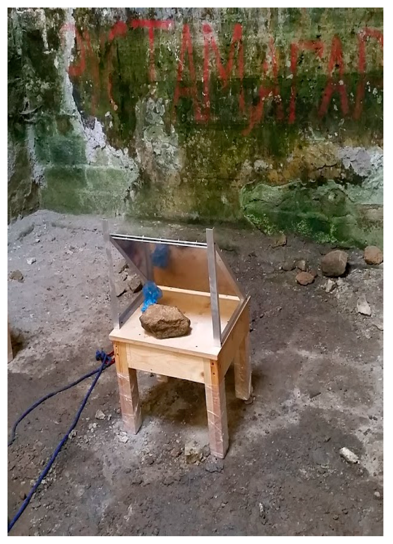
Figure 3 shows one of the nuclear emulsion detectors mounted inside the object.
3. Results
Estimates show [
17] that in order to distinguish the contours of the building against the ground by muon radiography, the difference in the density of the stone, used in the construction, and the surrounding soil should be at least 5%. The material characteristics and thickness of the construction walls are not known, and a preliminary simulation of muon passing through the building and their registration by emulsion detectors was carried out with several different values of wall thickness and density. In the calculations, loam of density 1.78 g/cm
3 was taken as soil material; sandstone of two density options (2.00 g/cm
3 and 2.65 g/cm
3) was taken as wall material. Simulation of the muon flux passage for the test experiment was carried out with consideration of the emulsion detector design based on Geant4 software package [
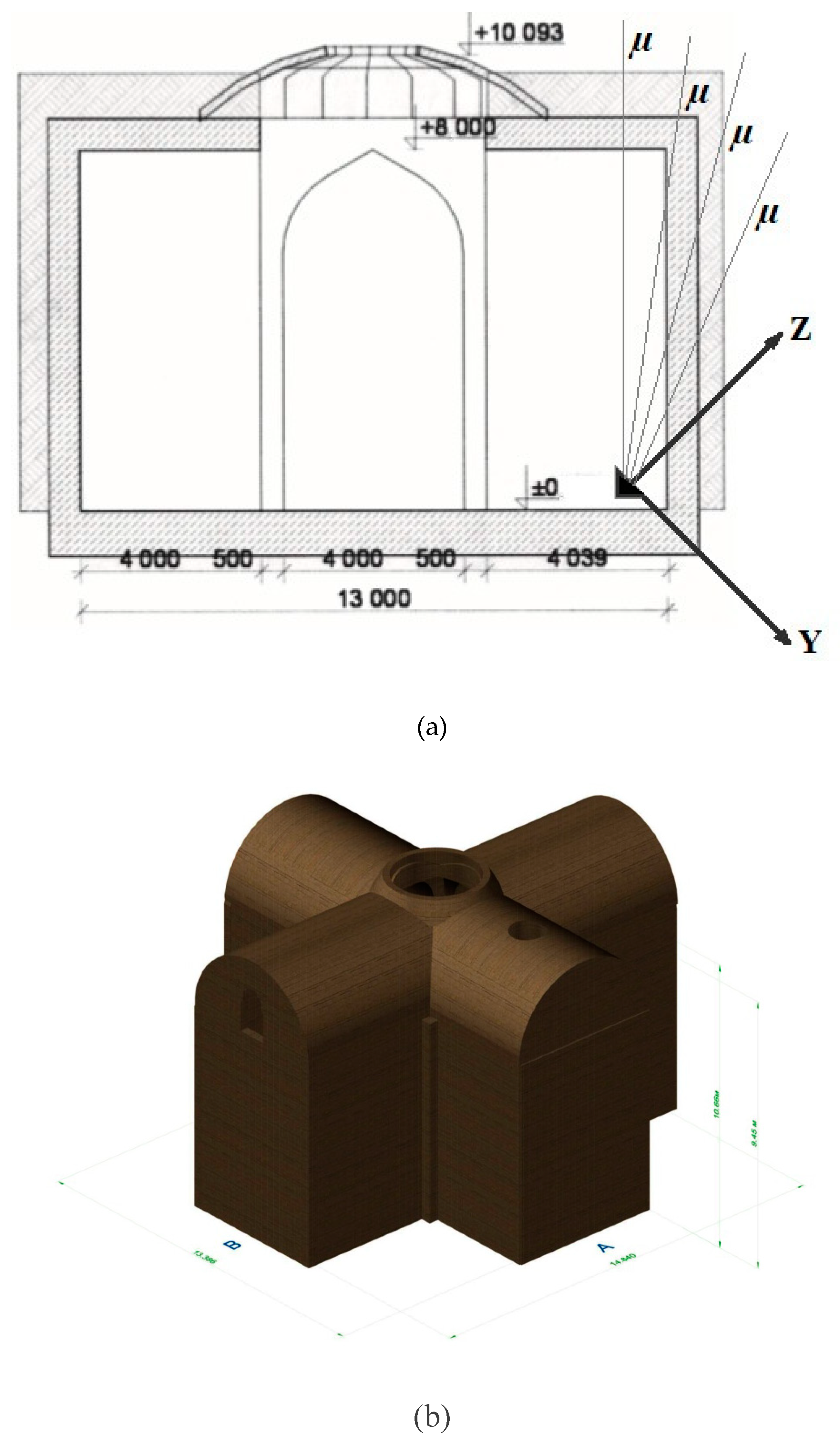
18]. When specifying the geometry inside the building studied (the widths and lengths of the corridors and the dome), the sizes shown in
Figure 4 were used.
The initial muon pulses were specified according to the experimentally obtained distribution [
19]. The dependence on the zenith angle θ was approximated by the function F(θ) ~ cos
2(θ); the distribution on the azimuth angle φ was taken uniform. In the calculations, a threshold value of the minimum pulse was taken above which a particle passes through a substance without stopping. Its value depends on the amount of substance in the particle path and, accordingly, varies with the angle of observation. Therefore, part of the initial muon spectrum above this minimum pulse is used in the simulation. The value of the recorded particle flux depends on the amount of material passed. Thus, for sandstone of density 2.3 g/cm
3 the flux passing through 3 m, 5 m and 10 m is attenuated by 35%, 2.5-fold and 5-fold at minimal pulse values of 1.56 GeV/s, 2.6 GeV/s and 5.25 GeV/s, respectively.
When a flux of particles passes through a layer of a substance of any thickness, up to several kilometers, the output will always contain particles of small energies that have pulses close to the minimal value when entering the substance. They are scattered rather strongly and affect the angle distribution of the registered particle fluxes. To take into account the blurring of the distribution of such particles due to their multiple scattering, and to optimize the simulation time, a special algorithm has been developed that reduces the effect of this mechanism.
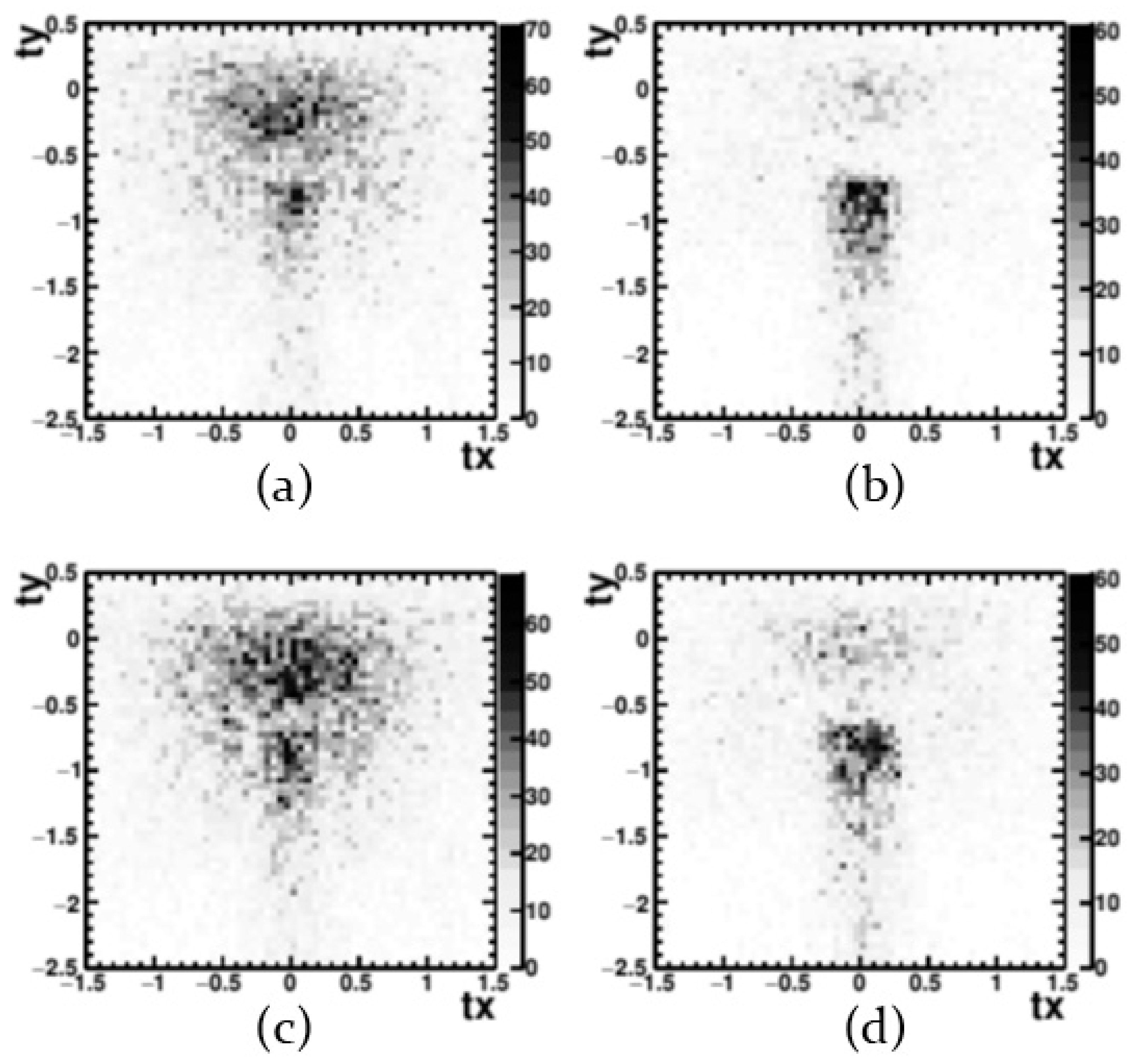
Figure 5 presents the simulation results in the form of distributions of the number of muons registered by emulsion detectors as functions of the angular variables
tx and
ty. The angular variables
tx and
ty represent the tangents of the slope angles of tracks in projections on the planes (xz, yz) and are related to the customary angular variables as follows:
where φ and θ are azimuth and zenith angles.
The simulation was carried out for two values of wall material density (2.00 g/cm3 and 2.65 g/cm3) and two values of wall thickness (0.5 m and 1.5 m). The muon decays and the angular dependence of their flux were taken into account, and calculations were made for particles with incident angles 0o < θ < 90o.
The maximal value of the initial muon flux obviously corresponds to the vertical direction (with increasing zenith angle θ the flux drops). In
Figure 5, at a wall density of 2.00 g/cm
3, the peak at ty = –0.8 corresponding to the vertical direction is clearly seen. At a wall density of 2.65 g/cm
3, the peak is weaker due to a significant increase of muon absorption. The distributions in
Figure 5 show that the change of wall thickness in the analyzed range has the largest impact on the number of passed particles, since the threefold increase in the wall thickness (from 0.5 m up to 1.5 m) changes the degree of absorption significantly more than the change in the density of material by 25%, from 2.00 g/cm
3 up to 2.65 g/cm
3.
The test irradiation of emulsion detectors in the Naryn-Kala citadel lasted for two months. After exposition the detectors were moved to the surface and disassembled; the nuclear emulsions were developed and processed. Scanning of the emulsion layers and online processing of the obtained images was carried out on the automated scanning complex PAVICOM [
20]. The most resource-consuming stage of the online processing is the reconstruction of microtracks – segments of tracks between pairs of track-forming grains, for which the track length and slope are within a certain range. Further offline data processing is performed with the FEDRA (Framework for Emulsion Data Reconstruction and Analysis) package [
21] providing for reconstruction of tracks, the relative position of emulsion plates in space and the track reconstruction in the entire volume of the scanned data.
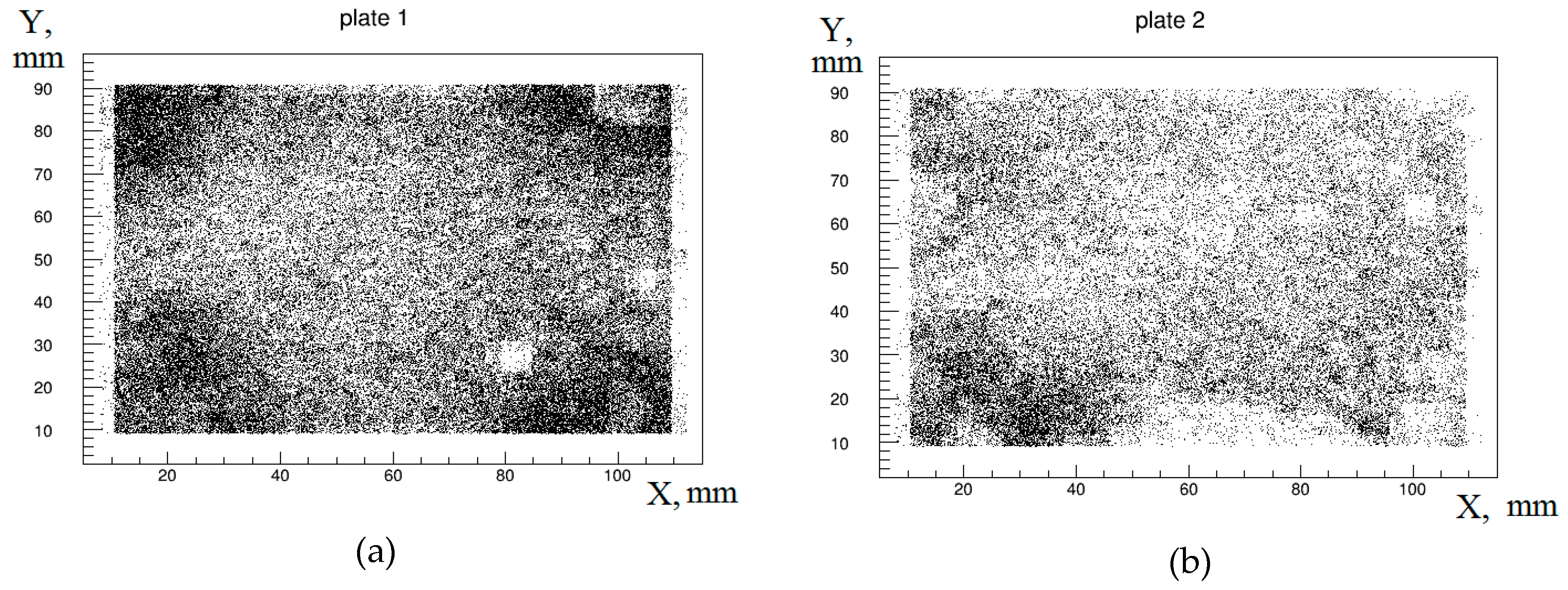
Figure 6 shows examples of image reconstruction in two adjacent films of one element of five exposed emulsion detectors. Each black dot on the Figure corresponds to one so-called base track passing through the upper and lower surface of one emulsion plate. The presented distributions demonstrate irregularity in the density of the reconstructed tracks in the XY plane.
Irregularity in the density of the reconstructed tracks can be associated, in particular, with characteristics of the emulsion, including a large fog (spontaneously developed silver grains) in one of the layers of the double-sided emulsion film. As a result of different number of the reconstructed grains forming a track on each of the emulsion layers, the number of tracks passing through the entire emulsion volume may include a number of background tracks. Another reason for the observed irregularity in the density of the reconstructed tracks may be the forced arrangement of detectors under conditions that are unfavorable for the exposure, when the water level at the detector location was about 30 cm from the floor. Nuclear emulsion is a material sensitive to changes in temperature and humidity, and gradients of these characteristics can cause local changes in material of the detector.
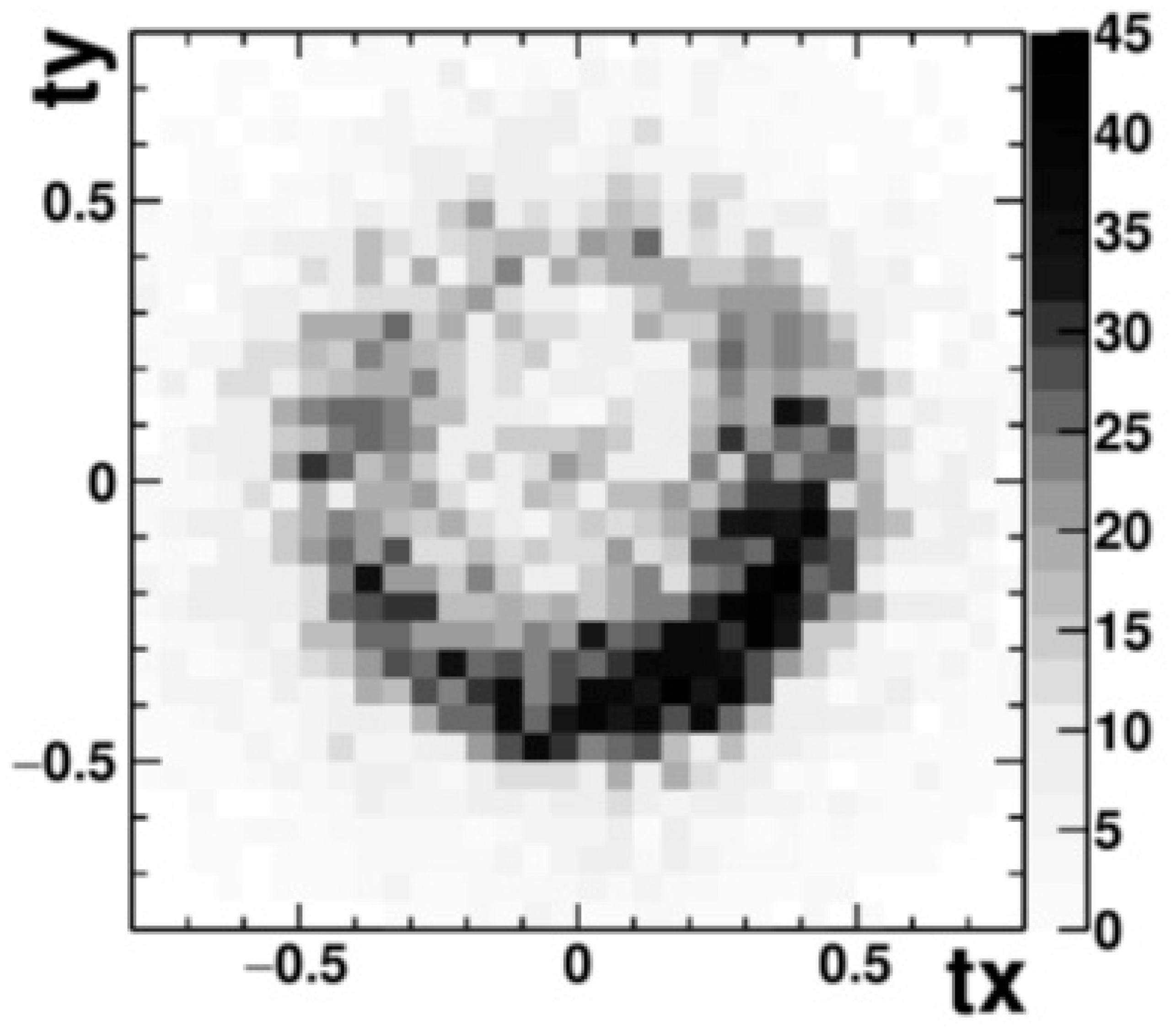
As an example of the result of processing the detector data from the test experiment with emulsions having retained the necessary characteristics,
Figure 7 presents experimental angular distribution of the muon flux in one of the exposed detectors (D). The distribution features a peak with displacement to the region
ty ~ −0.4 which can be explained by the influence of the detector efficiency function. There is a certain feature of the emulsion layers processing, which is that the effectiveness of the tracks selection depends on the incidence angle of the particle. The maximum detection efficiency corresponds to the perpendicular to the detector plane (Z-axis in
Figure 4). Muons from the vertical direction come to the detector at an angle of 45°, at which the registration efficiency is lower. Therefore, the peak of the angular distribution of muons in the detector is shifted. Some heterogeneity of the distribution at
ty > 0 indicates the presence of unevenness density at the ground level and underground. From the comparison of the obtained experimental distribution with the calculated one, it can be determined that this result is the closest to the simulated variant (b) in
Figure 5, with the relevant wall parameters L = 1.5 m and ρ = 2.65 g/cm
3. Since our model calculations were based on a hypothetical and simplified model of the object, some discrepancy between the simulation results and experimental data suggests that the real structure of the building is more complicated. We will conduct further research on the characteristics of this structure.

 ,
, 


