Performance Investigation of Solar ORC Using Different Nanofluids
by
Reyhaneh Loni
1, 
Gholamhassan Najafi
1,
Ezzatollah Askari Asli-Ardeh
2,
Barat Ghobadian
1,
Willem G. Le Roux
3 and
Talal Yusaf
4,* 
1
Department of Biosystem Engineering, Tarbiat Modares University, Pajouhesh Blvd, Tehran-Karaj Highway, Tehran 14115336, Iran
2
Department of Biosystem Engineering, University of Mohaghegh Ardabili, University Street, Ardabil 5619911367, Iran
3
Department of Mechanical and Aeronautical Engineering, University of Pretoria, Private Bag X20, Hatfield, Pretoria 0028, South Africa
4
Office of the Pro Vice Chancellor Federation University Australia, Victoria, Australia and School of Mechanical and Electrical Engineering, University of Southern Queensland, Toowoomba, QLD 4350, Australia
*
Author to whom correspondence should be addressed.
Appl. Sci. 2019, 9(15), 3048; https://0-doi-org.brum.beds.ac.uk/10.3390/app9153048
Submission received: 12 June 2019
/
Revised: 19 July 2019
/
Accepted: 19 July 2019
/
Published: 28 July 2019
(This article belongs to the Section Energy Science and Technology)
Abstract
:A parabolic solar dish concentrator, as the heat source of an organic Rankine cycle (ORC), can be used for power generation. Different types of tubular cavity receivers with different nanofluids can be considered for use in the solar dish collector to improve its efficiency. In the current research, an ORC with three different cavity receivers including hemispherical, cubical, and cylindrical are investigated using three nanofluids: Al2O3/oil, CuO/oil, and SiO2/oil. A numerical model is validated using experimental data. The ORC analysis is done for a constant evaporator pressure of 2.5 MPa, and condenser temperature of 38 °C. Methanol is employed as the ORC’s working fluid and a non-regenerative, ideal ORC system with different turbine inlet temperatures is considered. Furthermore, a fixed solar heat transfer fluid flow rate of 60 mL/s and dish diameter of 1.9 m is investigated. Results show that, compared to pure oil, the thermal efficiency of the cavity receivers increases slightly, and the pressure drop increases with the application of nanofluids. Furthermore, results show that the cubical cavity receiver, using oil/Al2O3 nanofluid, is the most efficient choice for application as the investigated solar ORC’s heat source.
1. Introduction
The importance of renewable energy increases as the world’s energy demand increases together with increasing environmental pollution and reduction of fossil fuel resources. Alternative and renewable energy resources should, therefore, be investigated. Solar energy is regarded as a favorable and clean renewable energy resource. The sun’s surface temperature is estimated as 5800 K. Solar collectors can be considered as an efficient way to absorb solar energy. A solar collector, such as a dish collector, can be considered as a heat exchanger for converting solar irradiance to thermal power. The sun’s rays can be absorbed very efficiently using concentrating solar collectors.
There are many research works which have numerically and experimentally investigated dish concentrators using cavity receivers. Kumar and Reddy [1] evaluated the heat losses from a modified cavity receiver due to natural convection theoretically. They presented a model to determine the Nusselt number due to natural convection heat loss. Jilte et al. [2] considered various cavity geometries using numerical methods. Their results presented models for the Nusselt number of the investigated cavity receivers under windy weather conditions. Various cavity receiver geometries for a dish concentrator were also investigated by Harris and Lenz [3]. Daabo et al. [4] determined the thermal and optical properties of a parabolic dish concentrator numerically using cylindrical, spherical and conical cavity shapes. The highest optical and thermal performance was found for the conical cavity receiver, and the highest optical efficiency was found for the conical cavity receiver. The first and second law efficiencies of a solar dish collector were numerically and experimentally investigated in Ref. [5] with water as working fluid. The cylindrical cavity receiver had the highest first and second law efficiencies.
A comprehensive review was presented by Wu et al. [6] on convection heat loss from cavity receivers. Mao et al. [7] investigated the effects of various parameters of a solar dish concentrator, such as incident solar irradiance, concentration ratio and optical error, on the solar heat flux distribution. It was concluded that the aspect ratio (receiver height vs. receiver diameter) and optical error has significant impact on the solar flux distribution. Le Roux et al. [8] numerically investigated and simulated a rectangular cavity receiver as a dish collector absorber. They used air as the heat transfer fluid in the solar receiver and found that the thermal efficiency of the investigated solar system increased as the tube diameter of the cavity receiver decreased. Also, Zhang et al. [9] modeled a power system using dish concentrators and parabolic trough collectors for a cascade system. They concluded that higher efficiencies can be achieved with higher solar irradiance. Loni et al. [10] investigated a dish concentrator, using a hemispherical cavity receiver, under windy conditions, both numerically and experimentally. An experimental model for the cavity heat losses due to wind was proposed.
The thermal properties of a fluid can be improved by the addition of suspended ultra-fine solid particles. A suspension with added nano-sized (1–100 nm) particles in a pure conventional fluid is known as a nanofluid. Some of the advantages of nanofluid usage are increased thermal conductivity and minimal clogging of flow passages [11]. Mahian et al. [12] performed a first and second law analysis of a minichannel-based solar collector with different water-based nanofluids (Cu/water, Al2O3/water, TiO2/water and SiO2/water). Their results showed that the Cu/water nanofluid had the lowest entropy generation rate and the highest outlet temperature. Mahian et al. [13] reviewed the application of nanofluids in various types of solar systems including solar collectors. Loni et al. [14] considered a dish concentrator using different nanofluids (Cu/oil, Al2O3/oil, TiO2/oil and SiO2/oil). They also concluded that the Cu/oil nanofluid had the best thermal performance. Furthermore, Loni et al. [15] experimentally investigated a solar dish concentrator with multi-walled carbon nanotubes (MWCNT/oil) as the solar working fluid. It was found that the application of the nanofluid improved the thermal performance of the investigated dish system. Aramesh et al. [16] numerically investigated the effect of different nanofluids in a solar pond. They concluded that single-walled carbon nanotubes (SWCNT/water) showed the best performance among the investigated nanofluids.
Finally, the organic Rankine cycle (ORC) system is a good candidate for converting thermal energy into electricity or mechanical power. The ORC heat source can be solar, geothermal, biomass, and waste heat energy sources. The application of solar energy as the ORC’s heat source has attracted much attention for efficient power generation. The studies on ORC firstly started in the 1970s, and advanced research works are still ongoing. A cavity receiver was optimized by Loni et al. [17,18]. It was concluded that the investigated system’s thermal performance can be improved by decreasing the inlet temperature and increasing the mass flow rate of the working fluid. Chang et al. [19] modeled a combined cooling, heat and power (CCHP) system, using solar energy and an ORC. They concluded that the environmental conditions, including solar irradiance and ambient temperature, had significant effects on the performance. Shaaban [20] investigated an integrated solar combined cycle (ISCC) using two bottoming cycles, including a steam Rankine cycle and an organic Rankine cycle. The cycle with R1234ze (Z) revealed an increase in the output power of the investigated cycle. Furthermore, Baccioli et al. [21] considered the dynamic behavior of a solar ORC with a compound parabolic collector (CPC) as heat source.
Considering the aforementioned literature review, nanofluid utilization in a dish collector is a growing research field. In the current research, the performance of an ORC cycle with three cavity receivers are considered and compared together, as a novel research. The three investigated cavity receivers include the cubical, cylindrical and hemispherical cavity receivers. As a novel idea in the current study, the thermodynamic analysis of the investigated solar ORC is examined using different types of nanofluids: Al2O3/oil, CuO/oil, and SiO2/oil. The ORC cycle analysis is performed at the evaporator pressure of 2.5 MPa and condenser temperature of 38 °C; also, methanol is employed as the working fluid.
2. Materials and Methods
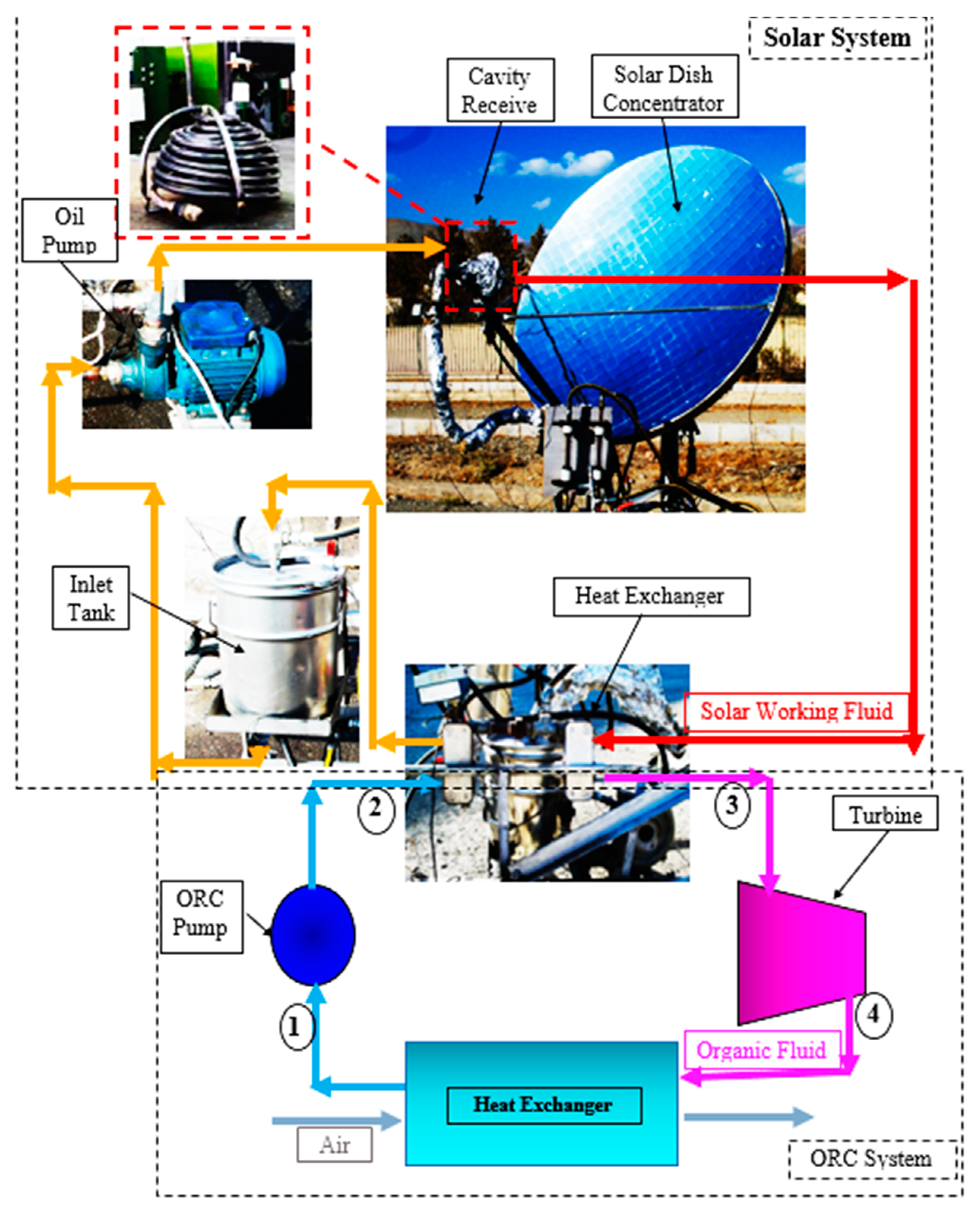
In this research, a solar ORC system is investigated for power generation using nanofluid application as the solar working fluid. A dish concentrator is investigated as the ORC’s heat source with different cavity receiver shapes (hemispherical, cylindrical and cubical). Various oil-based nanofluids are considered (CuO/oil, SiO2/oil and Al2O3/oil). A schematic of the investigated solar ORC system is presented in Figure 1. It should be mentioned that methanol is used as the ORC working fluid. The ORC system is investigated at constant evaporator pressure of 2.5 MPa and constant condenser temperature of 38 °C. In the current research, a numerical study is performed to determine the influence of nanofluids, and different nanofluid concentrations, on the ORC’s performance. The solar and ORC systems are presented in detail in the subsequent sections.
2.1. Solar System
The solar dish concentrator is optically and thermally investigated using SolTrace and Maple software. References [10,17,18], presented the numerical methodology for the hemispherical, cubical, and cylindrical cavity receivers using pure thermal oil. In the current paper, the optimized hemispherical, cubical and cylindrical cavity receivers are considered as the ORC’s heat source using different nanofluids. Three different cavity receiver shapes, each with good thermal performance, are therefore compared. As the cavity aperture area and depth decreases, the optical efficiency of the cavity receiver decreases, while the thermal efficiency of the cavity receiver increases. Consequently, the investigated cavity receivers have optimal dimensions. The main features and dimensions of these cavity receivers are shown in Table 1. All the structural characteristics were selected based on the real built cavities from Refs. [10,22].
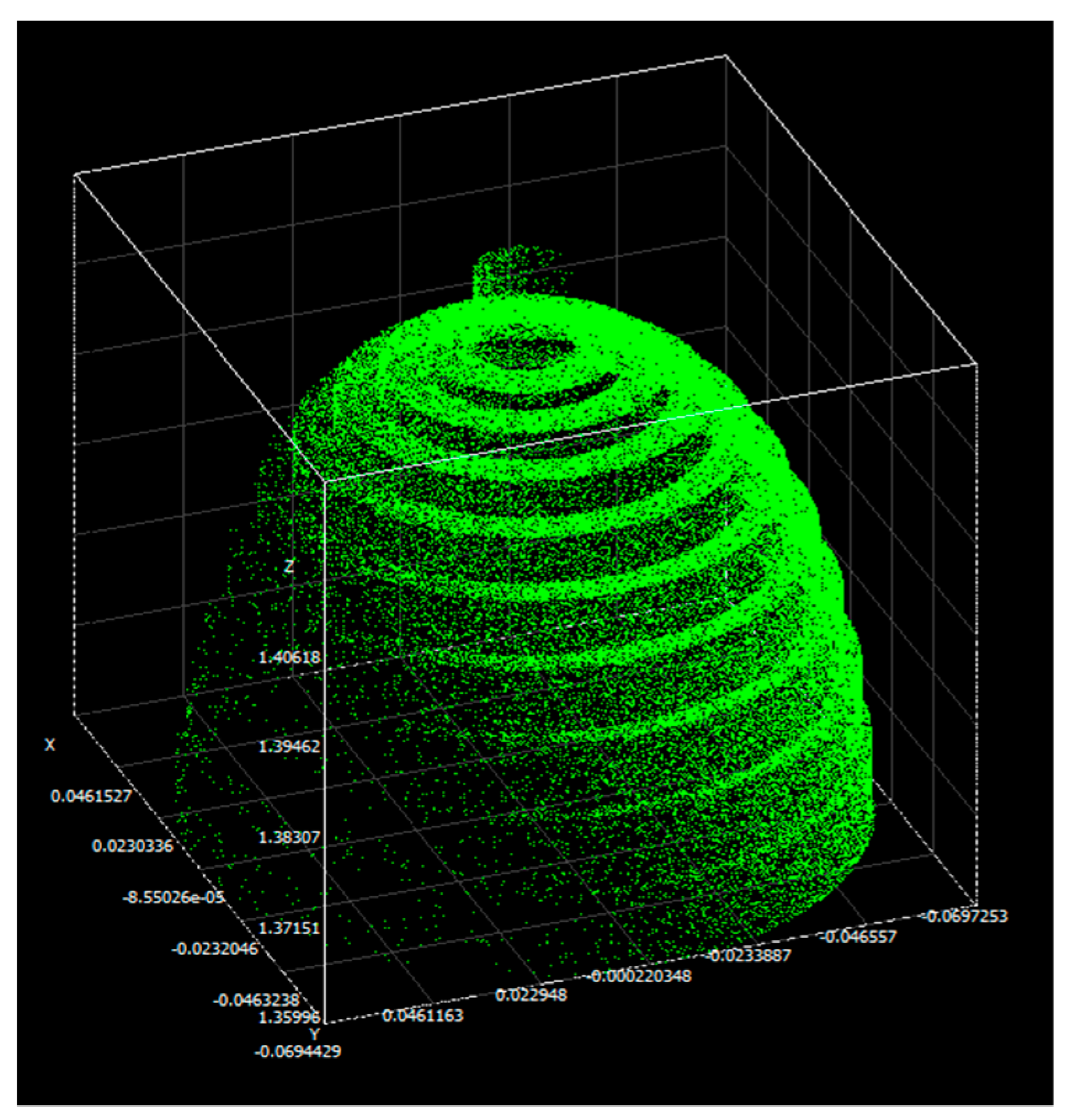
For the optical simulation of the cavity receivers a ray-tracing software, SolTrace [8], is used. A pillbox sun-shape is considered. Furthermore, the tracking error and optical error of the solar dish are assumed as 1° and 10 mrad, respectively [24]. The receiver tube absorptivity and the reflectivity of the solar dish are accounted for in SolTrace. Each coil of the hemispherical cavity receiver is defined separately in the optical analysis (see Table 1). Figure 2 shows that the one side of the hemispherical cavity receiver has a higher heat flux distribution due to the 1° tracking error assumption. It should be mentioned that the optical analyses of the hemispherical cavity receiver were presented in Ref. [23] in detail. For the cubical and cylindrical cavity receivers similar distributions have been found [17].
The thermal simulation of the hemispherical cavity receiver is discussed in this section, where the basic heat losses are due to conduction, convection and radiation. The net heat transfer rate is therefore calculated as:
The reflectivity ( of the dish concentrator is assumed as 0.84 [24]. Finally, the receiver’s thermal efficiency () can be defined as:
- Conduction and external convection heat losses
Equation (5) can be used for the determination of the conduction and external convection heat losses of the receiver. It should be mentioned that a thermal resistance approach was used for estimating the receiver heat loss due to the conduction and external convection. This approach was selected because of a specified cavity wall temperature and ambient temperature. The ambient temperature was assumed equal to 20.2 °C, and the cavity wall temperatures were determined as a variable based on the presented method as shown below. In this simulation, 2 cm-thick mineral wool was applied [25].
The Nusselt number is used to calculate the external convection heat transfer coefficient. Both forced and natural convection are taken into account. The Nusselt number for forced convection on the outside of the receiver insulation is [26]:
where
Also, the natural convection of the investigated hemispherical cavity receiver is calculated as [26]:
The combined Nusselt number (taking both forced and natural convection into consideration) is calculated as [26]:
Finally, the overall convection heat transfer coefficient is expressed as:
- Radiation heat loss
The radiation heat loss of the hemispherical cavity receiver is calculated based on the Nusselt number. The Nusselt number of radiation () for a hemispherical cavity receiver is expressed as [27]:
where
The cavity receiver is coated with black chrome with emissivity of 0.1. The total heat loss rate from the receiver`s aperture due to radiation can be determined as:
- Convection heat loss
The total heat transfer coefficient for convection heat loss from the cavity is determined by using forced and natural convection equations [28]:
For the hemispherical cavity receiver surface, the convection heat loss rate is presented by Equation (21):
Numerical methods are used to calculate the net heat transfer rate along the tube length according to Ref. [8]. Note that the fluid enters at the bottom of the investigated cavity receiver. The cavity receivers were divided into smaller elements along the tube length. A view of the location of the elements is presented in Figure 3.
The useful heat is calculated as:
The Nusselt number is determined with Equation (23):
The friction factor () is found using following equation:
Furthermore, the heat transfer coefficient is determined with Equation (25):
Therefore, based on Equation (1) and using SolTrace to get , the net heat gain can be found using Equations (22) and (26):
The analysis is performed using real meteorological data from a typical day (20 October 2016) in Tehran, Iran at 12:00 p.m. (see Table 2). It should be emphasized that the receiver tube of the cavity receiver is divided into a number of shorter sections, where each round of cavity tube is assumed as one element. Furthermore, the thermal modeling was developed using Maple software [18].
Oxide nanoparticles including Al2O3, CuO, and SiO2 (30–50 nm), were examined in the solar system. Table 3 shows the thermal properties of the nanoparticles at ambient temperature of 25 °C. It should be mentioned that the nanofluids were investigated based on volume fraction of 3%. Note that these nanoparticles have a low specific heat, high thermal conductivity and high density.
The thermal properties of the nanofluids are determined using Equations (28)–(31), according to the properties of the nanofluid (nf), the nanoparticle (np) and the base fluid (bf). The thermal conductivity is calculated as shown below [29], where β (assumed to be 0.1 [30]) is the ratio of the nanolayer thickness to the diameter of the nanoparticles.
The dynamic viscosity is determined using the Batchelor model [33]:
2.2. Organic Rankine Cycle (ORC) System
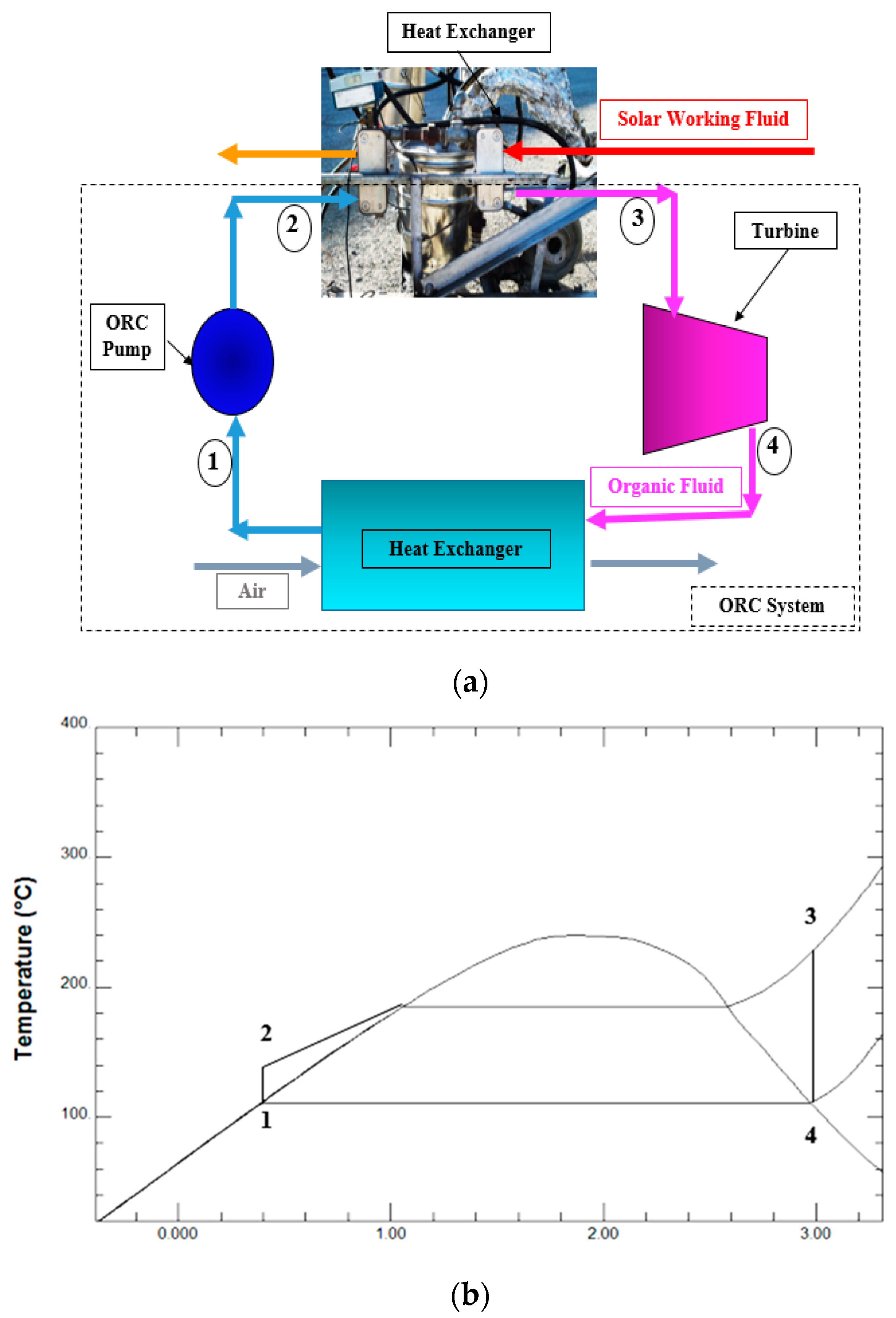
In this section, the investigated ORC system is presented in detail. A schematic, and T-s diagram of the ORC system are presented in Figure 4a,b, respectively. The ORC system consists of an evaporator, a condenser, a pump and a turbine. A heat exchanger is used as the ORC evaporator. The heat absorbed by the solar dish collector is transferred to the ORC working fluid by the heat exchanger at constant pressure of 2.5 MPa (during process 2–3 in Figure 4). The ORC working fluid phase changes to a saturated or superheated fluid in the heat exchanger. The saturated or superheated fluid enters the turbine for power generation at isentropic conditions (during process 3–4 in Figure 4). Afterwards, the ORC working fluid is cooled by the condenser at constant pressure (during process 4–1 in Figure 4). It should be mentioned that the condenser operates at a constant temperature of 38 °C. Finally, the cooled organic fluid is pressurized by the pump at isentropic conditions (during process 4–1 in Figure 4). It should be noted that methanol is used as the ORC’s working fluid.
REFPROP.8 software [34] is used to determine the working fluid’s thermodynamic properties. It should be mentioned that thermodynamic analyses were conducted using the Maple and REFPROP.8 software [14]. For simplicity, the internal irreversibility, the heat exchanger and pipeline pressure drop and the heat loss from the pipelines are neglected. Furthermore, it is assumed that each component of the ORC operates as a steady-flow system.
Irreversibility acts as a barrier for conversion of thermal energy into work in a real system. Therefore, irreversibility affects the efficiency of a cycle and can be used to determine the efficiency. The total irreversibility rate can be approximated with [35]:
In the following, a list of the equations is presented for performing the thermodynamic analysis [36].
Evaporator:
The mass flow rate of the ORC working fluid is evaluated as shown in Equation (34):
in which
Turbine:
Condenser:
Pump:
The net power generation can be calculated as shown below:
The overall efficiency of the solar ORC system is defined in Equation (40):
Table 4 shows the input data of the solar ORC system. Input data were selected based on the reported optimal data by Ref. [37]. The aim of this study is to consider the effects of turbine inlet temperature (TIT) of the ORC working fluid, different shapes of the cavity receiver and different nanofluids as the solar working fluid of the ideal solar ORC system. The efficiency of the pump and heat exchanger is therefore assumed equal to 100%.
The ORC working fluids can be categorized as dry fluids, wet fluids, and isentropic fluids. Selection of the appropriate working fluid is needed to achieve maximum efficiency. Note that methanol was selected for this study, because of its high thermodynamic performance as reported in Ref. [36]. As concluded in Ref. [36], methanol resulted highest thermodynamic performance with lowest irreversibility as the ORC working fluid among some examined organic fluids including R113, R601, R11, R141b, ethanol, and methanol. Also, methanol is presented as an appropriate working fluid for medium to high-temperature systems such as the examined solar system in the current research. Regarding the environmental properties of methanol, it is investigated as an environmentally friendly fluid with low global warming potential of 2.8 at 100 years (GWP 100), health hazard (H) of 1, and flammability (F) of 3 [38]. The thermo-physical properties of methanol are shown in Table 5.
2.3. Validation with Experimental Results
The calculated results by the developed numerical model were validated based on experimental tests. A schematic of the investigated experimental setup is shown in Figure 5. It should be mentioned that the validation section was presented based on the reported experimental results in Ref. [39] by the authors. A summary of the experimental tests is presented here. As shown in Figure 5, the experimental setup consisted of a dish concentrator system with aperture diameter of 1.9 m, cavity receiver with aperture diameter of 12.5 cm and cavity tube diameter of 10 mm, an oil pump, an inlet tank and a heat exchanger. The dimensions and properties of the experimental dish and cavity receiver are shown in Table 6. Experimental tests were conducted at the Renewable Energy Research Center of Tarbiat Modares University, Tehran, Iran (35.68° N latitude and 51.42° E longitude). Solar working fluid was pumped to the cavity receiver with the oil pump. The concentrated solar energy from the dish concentrator was absorbed by the solar working fluid in the cavity receiver. The absorbed heat by the working fluid is then cooled by the heat exchanger. Finally, the working fluid is depleted in the inlet tank for re-circulation in the solar system. It should be mentioned that the outlet and inlet temperatures of the solar working fluid at the cavity receiver were found using K-type thermocouples (Chromel-Alumel). The volume flow rate of the working fluid was determined with a volume flow meter (FLUIDWELL model: F016-P). Also, ambient conditions such as wind speed and solar radiation were measured using an anemometer (CT model: AM-4220) and Hukseflux pyranometer (model: SR12), respectively. The average uncertainty of the thermal efficiency was found to be about 1.06% using Equation (41). The uncertainty and ranges of the measuring instruments are given in Table 7.
The cavity receiver was constructed during three stages: coiling the copper tube, coating the receiver tubes with a black chrome (Cr-Cr2O3) as selective coating for increasing absorption, and insulating the cavity receiver with mineral wool for reducing heat losses. The specifics of the materials used in the construction of the cavity receiver are given in Table 8.
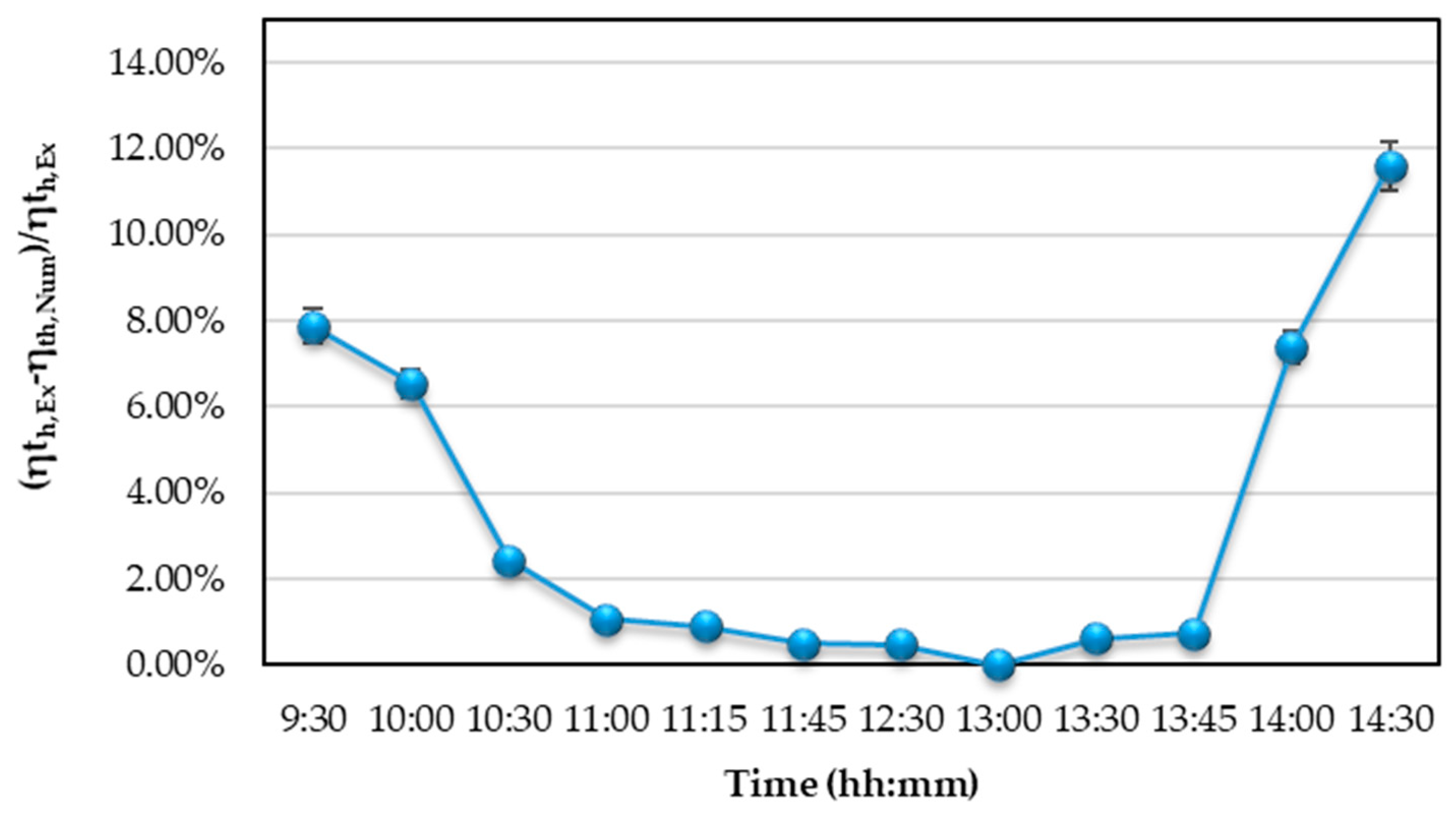
A comparison between measured experiment data and calculated numerical results are presented in Table 9. It should be mentioned that actual ambient conditions were inputted into the numerical model and used to obtain numerical results. As shown, the mean thermal efficiency deviation is 3.34% which is acceptable for the accuracy model. Also, the deviation variation during the day is presented in Figure 6. As concluded from Table 9, there are acceptable values at noon when the cavity receiver is in the steady-state condition.
3. Results
Figure 7 depicts the variation of the cavity surface temperature along the cavity tube for the three investigated cavity receivers using thermal oil and a dish diameter of 1.9 m (see Table 1). Results show that the surface temperature of the hemispherical cavity receiver is the highest compared to the other cavity receivers. This is because of the higher heat flux intensity on the hemispherical cavity receiver (see Figure 8 as generated with SolTrace when Isun is set to 1000 W/m2). Note that the surface temperature data for all of the investigated cavity receivers in Figure 7 compares well with the cavity heat flux data in Figure 8. The presented results in Figure 7 can be compared with the reported results by Refs. [17,18] for rectangular and cylindrical cavity receiver as solar dish absorber, respectively. In this research, variation of cavity surface temperature was presented and compared for three shapes of cavity receivers including hemispherical, cubical, and cylindrical cavities as a new achievement.
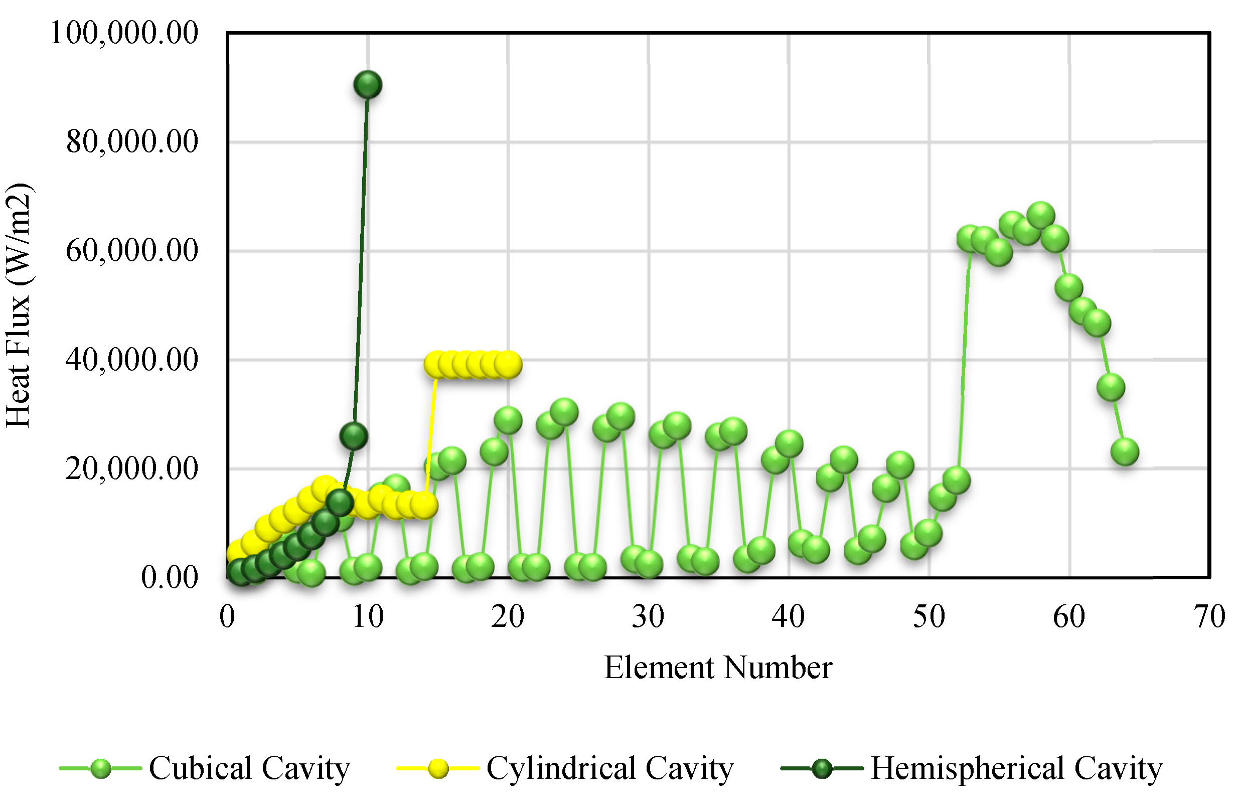
The heat flux (Figure 8) in the hemispherical cavity receiver is highest in the central element of the cavity tube where most of the solar rays intersect with the receiver. Note that, for the cylindrical cavity receiver, there is a sudden increase in heat flux at the 15th element. This is due to high amounts of concentrated solar irradiance at the top surface of the cylindrical cavity receiver where the 15th to 21st elements are located. This sudden increase is also observed in the 53rd to 64th elements of the cubical cavity receiver. These elements, located at the top wall of the cubical cavity, absorb higher amounts of solar heat flux compared to the cavity elements located at the side walls of the cubical cavity receiver. Smaller heat flux spikes are also observed on the side wall elements. This is due to the tracking error of 1° for the investigated solar dish concentrator. The intensity of the solar heat flux is, therefore, higher at two cavity side walls of the cubical cavity receiver compared to the other two side walls. Consequently, this causes a sudden increase or decrease in heat flux from the 1st to the 52nd element. Similar results were presented by Refs. [17,18] for the rectangular and cylindrical cavity receivers. In the current study, a comparison of heat flux distribution was presented for three investigated cavity receiver including hemispherical, cubical, and cylindrical cavities as a new achievement. A similar pattern is observed for the cavity surface temperatures in Figure 7. The net heat transfer rate along the length of the three investigated cavity receivers is displayed in Figure 9. Note that the net heat transfer rate per element is the highest for the hemispherical cavity receiver. This is because of the high heat flux rate on the hemispherical cavity receiver, as discussed in the previous paragraph.
Figure 9 depicts variation of the net heat transfer rate along the cavity receivers using weather conditions of 20th October 2016, Tehran, Iran. As observed from Figure 10, the maximum solar power is at the 7th element in the hemispherical cavity receiver. Furthermore, variation of available solar power along the cavity tubes for different investigated cavity receives is presented in Figure 10 based on the calculated results by the SolTrace software. Note that the net heat transfer rate shows a similar pattern when compared to the available solar power () in Figure 10 (as generated with SolTrace when Isun is set to 1000 W/m2). Finally, Figure 11 shows the working fluid outlet temperature per element along the lengths of the cavity receivers. It should be mentioned that pure thermal oil was investigated as heat transfer fluid in this section of analyses. It is concluded that the outlet temperature of the hemispherical cavity receiver is the highest. According to Figure 11, the elemental outlet temperatures always increase along the cavity tube, since the heated working fluid from a previous element enters the next element. The outlet temperature increases more rapidly at the top wall elements of the cubical and cylindrical cavity receivers. This is because of higher solar heat flux at the cavity top wall as stated previously. Similar achievements are reported by other papers including [17,18] for a solar dish concentrator with rectangular and cylindrical cavity receiver. A comparison study was presented in this research for different thermal performance parameters such as solar heat flux, absorbed heat, and outlet temperature for three investigated cavity receivers including the hemispherical, cubical, and cylindrical cavities as a new result.
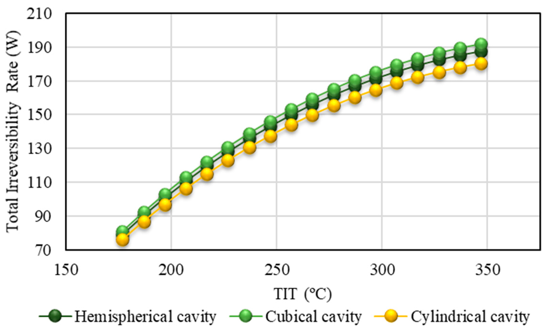
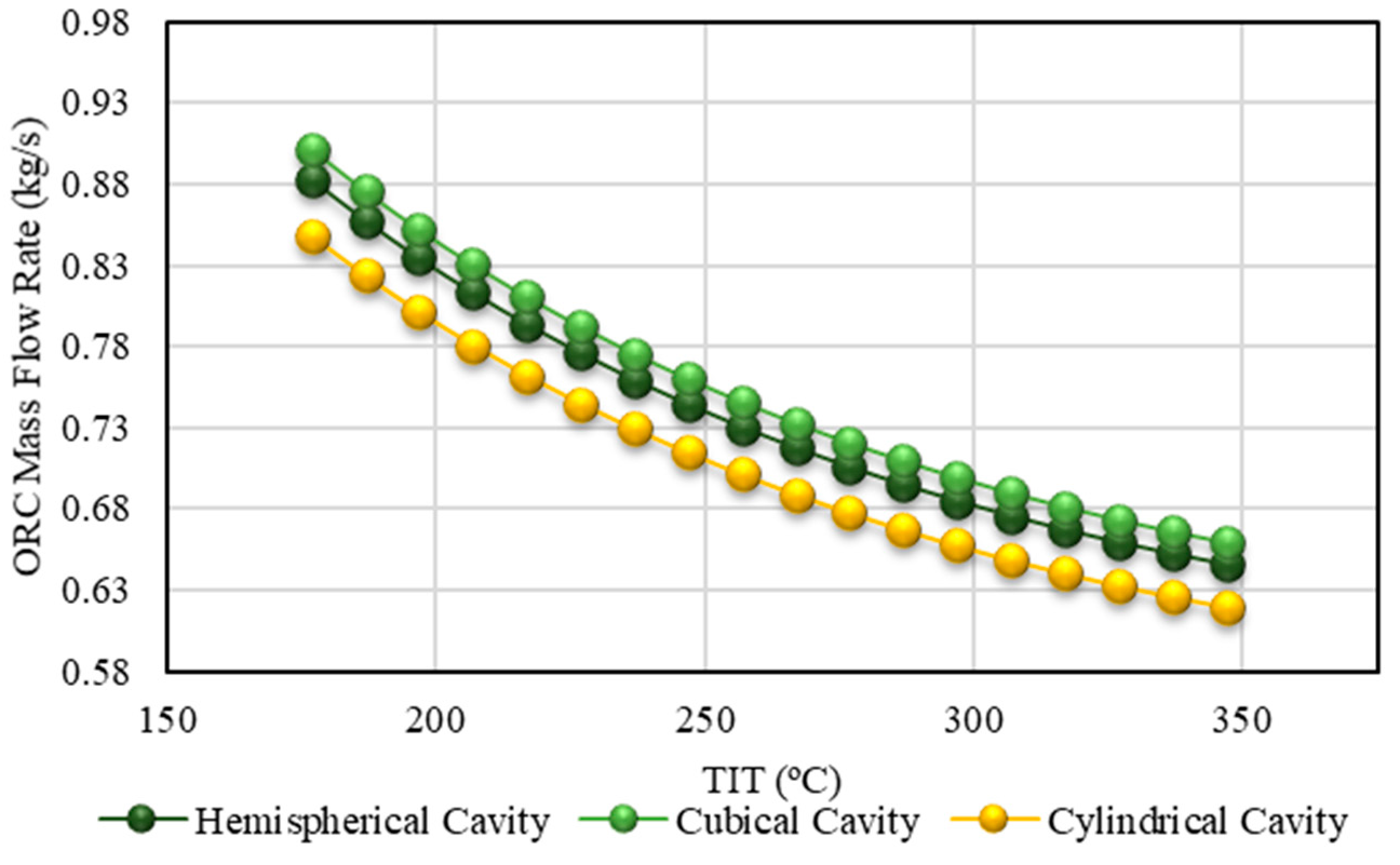
In this section, performance of a solar ORC system with different shapes of the cavity receivers is considered including the hemispherical, cylindrical, and cubical cavity receivers. Thermal oil and methanol were used as the solar working fluid, and ORC working fluid. Inlet temperature of the solar heat transfer fluid was assumed to be equal to 40 °C, and 632.97 W/m2, respectively. Figure 12 shows variation of the total irreversibility versus turbine inlet temperature (TIT) for different shapes of the cavity receivers as the ORC heat source. Note that the total irreversibility rate of the cubical cavity receiver is the highest. This is because of a higher ORC mass flow rate required, for a specific inlet temperature, when using the cubical cavity receiver (Figure 13). The ORC mass flow rate for the cubical cavity receiver is the highest because it gains the most heat, based on Table 10. It is also concluded from Table 10 that the thermal efficiency and the pressure drop of the cubical cavity receiver is the highest. Furthermore, Figure 12 shows that the total irreversibility rate of the three investigated cavity receivers increases with increasing TIT of the ORC system. For all three cavity receivers, the mass flow rate of the investigated solar ORC decreases with increasing TIT of the ORC system. Similar results were concluded by Ref. [36] for a cubical cavity receiver as heat source of an ORC system. In the current study a performance comparison of different shapes of cavity receiver including hemispherical, cylindrical, and cubical cavity receivers is presented as heat source of the ORC system for selecting the best system for power generation.
In this part, the results for the different nanofluid applications in the investigated solar ORC are also presented. The influence of the application of different cavity receiver as the ORC’s heat source is studied using application of different nanofluid as the solar working fluid. The hemispherical, cylindrical, and cubical cavity receivers were used as the ORC heat source. Different nanofluids including oil/Al2O3, oil/CuO, and oil/SiO2 nanofluids were considered as the solar working fluid with nanofluid concentration of 3% volume fraction. The solar system was investigated at solar radiation of 632.97 W/m2, working fluid inlet temperature of 40 °C, and working fluid flow rate of 60 mL/s. The ORC system was considered at constant turbine inlet temperature of 229 °C, and turbine inlet pressure (TIP) of 2.5 MPa. Table 11 displays the variation of the thermal parameters of the hemispherical cavity receiver using different nanofluids (oil/Al2O3, oil/CuO, and oil/SiO2) (also see Table 12 and Table 13 for the cubical and cylindrical receiver, respectively). Note that the thermal performance, in terms of cavity heat gain, thermal efficiency, and outlet temperature of the solar working fluid, has been increased slightly by the application of nanofluids. Also, note that the pressure drop of the solar system is increased by the application of nanofluids, when compared to pure oil. As seen, the cubical cavity receiver has the highest thermal performance using oil/Al2O3 nanofluid as the solar working fluid. Similar studies were conducted (see Refs. [40,41]) where the influence of nanofluid application, as solar working fluid of a dish concentrator with a spiral cavity receiver, was investigated using energy and exergy analyses. Similar results were reported by Refs. [40,41]. In the current study, application of different oil-based nanofluids as heat source of an ORC system with different shapes of cavity receivers as the ORC heat source is presented as a new subject for study.
A comparison of the percentage improvement of the ORC net power output, and overall efficiency between three cavity receivers, is presented in Table 14 and Table 15, respectively. It is shown that the different types of nanofluids did not have a significant effect on improving the ORC overall efficiency. This is due to the short length of the cavity tube and the short amount of time in which the nanofluid has to absorb the solar thermal energy. It should be noted that the result is therefore based on the specific mass flow rate which was investigated in this work. Furthermore, the application of SiO2/oil nanofluid had the smallest effect on improving the ORC performance, while for the cubical cavity receiver, using Al2O3/oil, had the largest effect on improving the ORC performance. The cubical cavity receiver, using Al2O3/oil is, therefore, recommended as the heat source for the investigated solar ORC with the specific solar heat transfer fluid mass flow rate which was investigated in this work. The calculated results related to enhancement of the solar system performance can be compared with reported results by Ref. [42]. Bellos and Tzivanidis [42] investigated performance of a solar concentrator system using different nanofluids including 3% Al2O3/Oil, 3% TiO2/Oil, and 1.5% Al2O3/Oil and 1.5% TiO2/Oil. They reported improvement lower than 1% for the investigated solar system using different nanofluids. The cavity receivers have very small thermal losses and so there is not such a high thermal enhancement margin. Therefore, the use of nanofluids as a thermal enhancement method can enhance the performance up to 2%–3% maximum. The calculated results can be compared with the results reported in Ref. [43], where the effect of alumina/oil nanofluid, with different size and volume fractions, was investigated as solar working fluid for a solar ORC. In the current research, performance of the solar ORC system using different nanofluids including oil/Al2O3, oil/CuO, and oil/SiO2 nanofluid of the solar working fluid is a new subject for assessment.
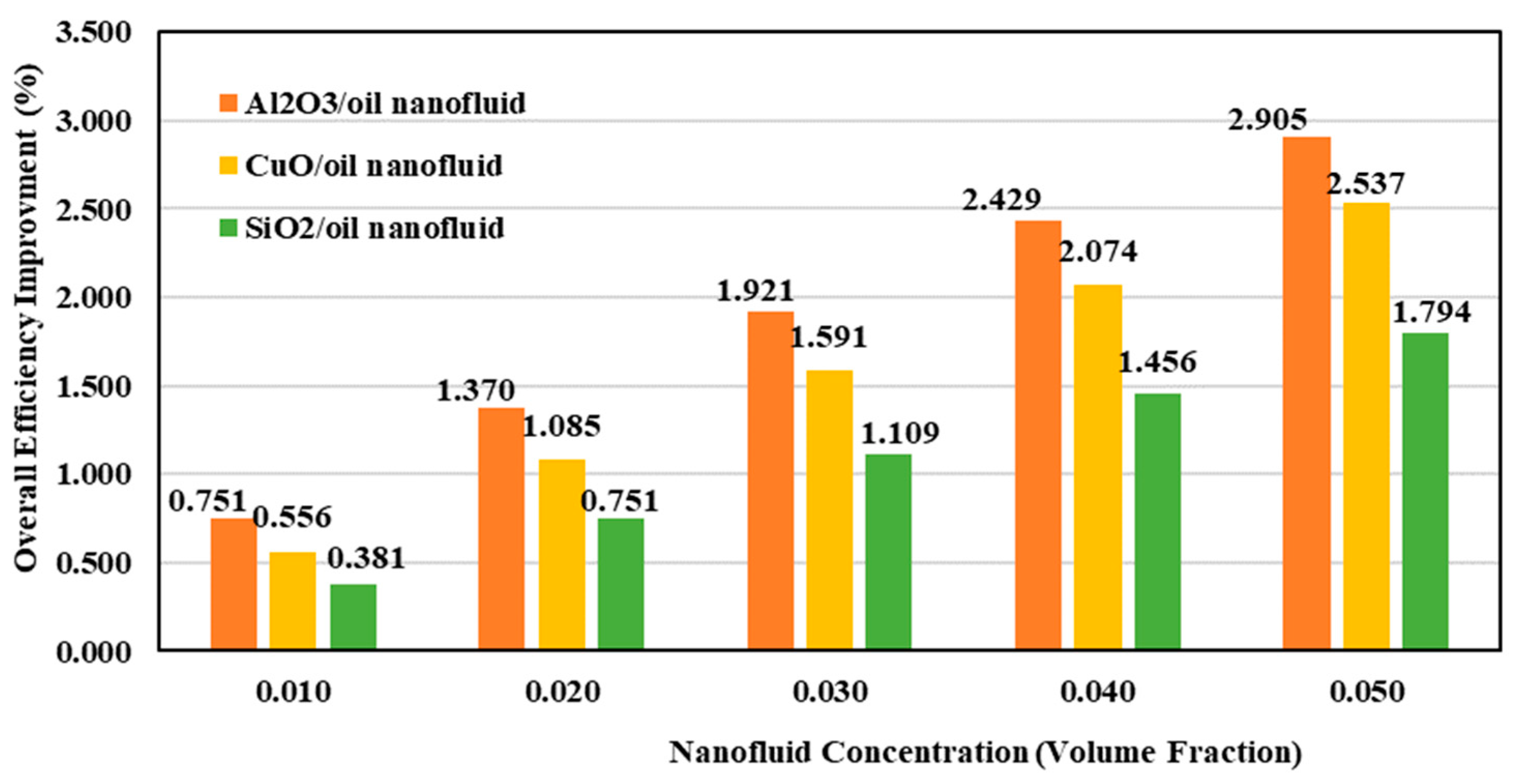
Finally, Figure 14 shows the variation of overall efficiency improvement of the solar ORC system with the variation of nanofluid concentration. The cubical cavity receiver was used as the dish absorber. Different nanofluids including oil/Al2O3, oil/CuO, and oil/SiO2 were considered as the solar working fluid. The solar system was investigated at working fluid inlet temperature of 40 °C, and solar radiation of 632.97 W/m2. The ORC system was considered at constant turbine inlet temperature of 229 °C, and turbine inlet pressure of 2.5 MPa. Methanol was used as the ORC working fluid. As shown in Figure 14, the thermal efficiency resulted higher improvement using application of Al2O3/oil nanofluid with higher nanofluid concentration. Generally, thermal performance improvement was calculated to be between 1% and 2%, as was reported in results by Ref. [42].
4. Conclusions
In the current paper, an ORC system with a dish collector heat source was considered. Three types of tubular cavity receivers including cubical, cylindrical and hemispherical were examined in the current study. Also, four types of nanofluids including Al2O3/oil, CuO/oil, and SiO2/oil were considered as the solar heat transfer fluid. Experimental results of the hemispherical cavity receiver operating with thermal oil were used to validate a numerical model. The solar ORC analysis was under superheated conditions, with a constant evaporator pressure of 2.5 MPa, and a condenser temperature of 38 °C. Methanol was considered as the ORC working fluid. A fixed solar heat transfer fluid mass flow rate of 60 mL/s and dish diameter of 1.9 m was investigated. Results showed that the working fluid outlet temperature, and thermal efficiency is the highest for the cubical cavity receiver. Also, the total irreversibility rate of the ORC, the ORC mass flow rate, and the ORC overall efficiency are the highest for the cubical cavity receiver. Furthermore, it was shown that the total irreversibility rate of the three cavity receivers investigated is increased by increasing the TIT of the ORC system. Results showed that the pressure drop through the cavity receivers was increased by the application of nanofluids. For all three cavity receivers, different thermal parameters were insignificantly increased with the application of nanofluids. Further improvements are recommended based on the optimization of variables, such as the mass flow rate, fixed in this work. The application of the SiO2/oil nanofluid had the lowest effect on improving the ORC performance. The cubical cavity receiver, using oil/Al2O3, was found to be the most efficient choice for application as the investigated solar ORC’s heat source. Finally, the thermal efficiency improved with about 2%–3% using the application of Al2O3/oil or CuO/oil nanofluid with higher nanofluid concentration as the solar ORC system’s working fluid.
Author Contributions
Methodology and investigation: R.L. and W.G.L.R.; supervision: E.A.A.-A. and B.G.; project administration: G.N. and T.Y.
Funding
Authors are grateful to the University of Mohaghegh Ardabili (UMA), and the Tarbiat Modares University (http://www.modares.ac.ir) for financial supports given under IG/39705 grant for renewable Energies of Modares research group.
Conflicts of Interest
The authors declare no conflict of interest.
Nomenclature
| a | receiver aperture side length, m |
| A | surface area, m2 |
| c2 | constant used in linear equation |
| constant pressure specific heat, J/kgK | |
| d | receiver tube diameter, m |
| D | diameter, m |
| Fn-j | view factor between surface n and surface j |
| friction factor | |
| g | gravitational constant, m/s2 |
| Gr | Grashof number |
| h | convection heat transfer coefficient, W/m2K |
| hrec | cavity depth, m |
| h* | enthalpy, kJ/kg |
| solar irradiance, W/m2 | |
| irreversibility rate, W | |
| k | thermal conductivity, W/mK |
| m2 | slope of linear equation |
| system mass flow rate, mL/s | |
| N | number of tube sections |
| NRC | radiation-conduction number |
| Nu | Nusselt number |
| ORC | organic Rankine cycle |
| P | pressure, Pa |
| Pr | Prandtl number |
| heat transfer rate, W | |
| net heat transfer rate, W | |
| rate of available solar heat at receiver cavity, W | |
| heat loss rate from the cavity receiver, W | |
| rate of available solar heat at dish concentrator, W | |
| R | thermal resistance, K/W |
| Ra | Raleigh number |
| Re | Reynolds number |
| t | thickness, m |
| T | temperature, K |
| TR | temperature ratio |
| TIT | turbine inlet temperature, K |
| V | volumetric flow rate (mL/s) |
| wind speed, m/s | |
| power, W | |
| temperature difference | |
| Greek symbols | |
| ϕ | volume fraction |
| volume expansion coefficient, 1/K | |
| β | nanolayer-thickness to nanoparticle-diameter ratio |
| δ | error |
| ϑ | kinematic viscosity of the fluid, m2/s |
| σ | Stefan–Boltzmann constant, W/m2K4 |
| emissivity | |
| efficiency | |
| cavity inclination angle, o | |
| dynamic viscosity, Pa.s | |
| density, kg/m3 | |
| Subscripts | |
| 0 | initial inlet to receiver |
| a | air |
| amb | ambient |
| ap | cavity aperture |
| ave | average |
| bf | base fluid |
| bp | boiling point |
| c | condenser |
| con | condenser |
| conc | concentrator |
| cond | due to conduction |
| conv | due to convection |
| cr | critical |
| D | diameter |
| evp | evaporator |
| Ex | experimental |
| exch | heat exchanger |
| f | fluid |
| forced | due to forced convection |
| H | heat source of the organic Rankine cycle |
| in | inner |
| inlet | at the inlet |
| inner | on the inside of the tube |
| ins | insulation |
| L | cold heat sink of the organic Rankine cycle |
| mt | turbine mechanical |
| n | tube section number |
| N | total number of tube elements |
| natural | due to natural convection |
| net | net |
| nf | nanofluid |
| np | nanoparticle |
| Num | numerical |
| oil | thermal oil |
| out | at the outlet |
| outer | outside of the cavity |
| ORC | organic Rankine cycle |
| P | pump |
| rad | due to radiation |
| rec | receiver |
| refl | reflection |
| s | surface |
| st | turbine isentropic |
| T | turbine |
| th | thermal |
| ∞ | environment |
References
- Kumar, N.S.; Reddy, K. Numerical investigation of natural convection heat loss in modified cavity receiver for fuzzy focal solar dish concentrator. Sol. Energy 2007, 81, 846–855. [Google Scholar] [CrossRef]
- Jilte, R.; Kedare, S.; Nayak, J. Investigation on convective heat losses from solar cavities under wind conditions. Energy Procedia 2014, 57, 437–446. [Google Scholar] [CrossRef]
- Harris, J.A.; Lenz, T.G. Thermal performance of solar concentrator/cavity receiver systems. Sol. Energy 1985, 34, 135–142. [Google Scholar] [CrossRef]
- Daabo, A.M.; Mahmoud, S.; Al-Dadah, R.K. The optical efficiency of three different geometries of a small scale cavity receiver for concentrated solar applications. Appl. Energy 2016, 179, 1081–1096. [Google Scholar] [CrossRef] [Green Version]
- Madadi, V.; Tavakoli, T.; Rahimi, A. First and second thermodynamic law analyses applied to a solar dish collector. J. Non-Equilib. Thermodyn. 2014, 39, 183–197. [Google Scholar] [CrossRef]
- Wu, S.-Y.; Xiao, L.; Cao, Y.; Li, Y.-R. Convection heat loss from cavity receiver in parabolic dish solar thermal power system: A review. Sol. Energy 2010, 84, 1342–1355. [Google Scholar] [CrossRef]
- Mao, Q.; Shuai, Y.; Yuan, Y. Study on radiation flux of the receiver with a parabolic solar concentrator system. Energy Convers. Manag. 2014, 84, 1–6. [Google Scholar] [CrossRef]
- Le Roux, W.; Bello-Ochende, T.; Meyer, J. The efficiency of an open-cavity tubular solar receiver for a small-scale solar thermal Brayton cycle. Energy Convers. Manag. 2014, 84, 457–470. [Google Scholar] [CrossRef] [Green Version]
- Zhang, C.; Zhang, Y.; Arauzo, I.; Gao, W.; Zou, C. Cascade system using both trough system and dish system for power generation. Energy Convers. Manag. 2017, 142, 494–503. [Google Scholar] [CrossRef] [Green Version]
- Loni, R.; Asli-Ardeh, E.A.; Ghobadian, B.; Kasaeian, A.; Gorjian, S. Numerical and experimental investigation of wind effect on a hemispherical cavity receiver. Appl. Therm. Eng. 2017, 126, 179–193. [Google Scholar] [CrossRef]
- Eastman, J.; Choi, U.S.; Li, S.; Thompson, L.J.; Lee, S. Enhanced Thermal Conductivity Through the Development of Nanofluids. In MRS Proceedings; Cambridge University Press: Cambridge, UK, 1996. [Google Scholar]
- Mahian, O.; Kianifar, A.; Sahin, A.Z.; Wongwises, S. Performance analysis of a minichannel-based solar collector using different nanofluids. Energy Convers. Manag. 2014, 88, 129–138. [Google Scholar] [CrossRef]
- Mahian, O.; Kianifar, A.; Sahin, A.Z.; Wongwises, S. A review on the applications of nanofluids in solar energy systems. Renew. Sustain. Energy Rev. 2015, 43, 584–598. [Google Scholar]
- Loni, R.; Asli-Ardeh, E.A.; Ghobadian, B.; Kasaeian, A.; Gorjian, S. Thermodynamic analysis of a solar dish receiver using different nanofluids. Energy 2017, 133, 749–760. [Google Scholar] [CrossRef]
- Loni, R.; Asli-Ardeh, E.A.; Ghobadian, B.; Kasaeian, A. Experimental study of carbon nano tube/oil nanofluid in dish concentrator using a cylindrical cavity receiver: Outdoor tests. Energy Convers. Manag. 2018, 165, 593–601. [Google Scholar] [CrossRef] [Green Version]
- Aramesh, M.; Pourfayaz, F.; Kasaeian, A. Numerical investigation of the nanofluid effects on the heat extraction process of solar ponds in the transient step. Sol. Energy 2017, 157, 869–879. [Google Scholar] [CrossRef]
- Loni, R.; Kasaeian, A.; Asli-Ardeh, E.A.; Ghobadian, B.; Le Roux, W.; Le Roux, W. Performance study of a solar-assisted organic Rankine cycle using a dish-mounted rectangular-cavity tubular solar receiver. Appl. Therm. Eng. 2016, 108, 1298–1309. [Google Scholar] [CrossRef]
- Loni, R.; Kasaeian, A.; Asli-Ardeh, E.A.; Ghobadian, B. Optimizing the efficiency of a solar receiver with tubular cylindrical cavity for a solar-powered organic Rankine cycle. Energy 2016, 112, 1259–1272. [Google Scholar] [CrossRef]
- Chang, H.; Wan, Z.; Zheng, Y.; Chen, X.; Shu, S.; Tu, Z.; Chan, S.H. Energy analysis of a hybrid PEMFC–solar energy residential micro-CCHP system combined with an organic Rankine cycle and vapor compression cycle. Energy Convers. Manag. 2017, 142, 374–384. [Google Scholar] [CrossRef]
- Shaaban, S. Analysis of an integrated solar combined cycle with steam and organic Rankine cycles as bottoming cycles. Energy Convers. Manag. 2016, 126, 1003–1012. [Google Scholar] [CrossRef]
- Baccioli, A.; Antonelli, M.; Desideri, U. Dynamic modeling of a solar ORC with compound parabolic collectors: Annual production and comparison with steady-state simulation. Energy Convers. Manag. 2017, 148, 708–723. [Google Scholar] [CrossRef]
- Loni, R.; Kasaeian, A.; Asli-Ardeh, E.A.; Ghobadian, B.; Gorjian, S. Experimental and numerical study on dish concentrator with cubical and cylindrical cavity receivers using thermal oil. Energy 2018, 154, 168–181. [Google Scholar] [CrossRef]
- Loni, R.; Asli-Ardeh, E.A.; Ghobadian, B.; Bellos, E.; Le Roux, W. Numerical comparison of a solar dish concentrator with different cavity receivers and working fluids. J. Clean. Prod. 2018, 198, 1013–1030. [Google Scholar] [CrossRef]
- Gorjian, S.; Ghobadian, B.; Hashjin, T.T.; Banakar, A. Experimental performance evaluation of a stand-alone point-focus parabolic solar still. Desalination 2014, 352, 1–17. [Google Scholar] [CrossRef]
- Melcome, K.K.S.H.; Mouradian, A.; Ajemian, A.; Ohan, N. Technical Information, Pashme Sang Iran; Engineering and Design Department: Tehran, Iran, 2002. [Google Scholar]
- Yunus, A.C.; Afshin, J.G. Heat and Mass Transfer; McGrawHill: New York, NY, USA, 2007. [Google Scholar]
- Reddy, K.; Kumar, N.S. Combined laminar natural convection and surface radiation heat transfer in a modified cavity receiver of solar parabolic dish. Int. J. Therm. Sci. 2008, 47, 1647–1657. [Google Scholar] [CrossRef]
- Kaushika, N.; Reddy, K. Performance of a low cost solar paraboloidal dish steam generating system. Energy Convers. Manag. 2000, 41, 713–726. [Google Scholar] [CrossRef]
- Yu, W.; Choi, S. The role of interfacial layers in the enhanced thermal conductivity of nanofluids: A renovated Maxwell model. J. Nanopart. Res. 2003, 5, 167–171. [Google Scholar] [CrossRef]
- Duangthongsuk, W.; Wongwises, S. An experimental study on the heat transfer performance and pressure drop of TiO2-water nanofluids flowing under a turbulent flow regime. Int. J. Heat Mass Transf. 2010, 53, 334–344. [Google Scholar] [CrossRef]
- Ayatollahi, M.; Nasiri, Sh.; Kasaeian, A.B. Convection heat transfer modeling of Ag nanofluid using different viscosity theories. IIUM Eng. J. 2012, 13, 1–11. [Google Scholar]
- Khanafer, K.; Vafai, K. A critical synthesis of thermophysical characteristics of nanofluids. Int. J. Heat Mass Transf. 2011, 54, 4410–4428. [Google Scholar] [CrossRef]
- Batchelor, G. The effect of Brownian motion on the bulk stress in a suspension of spherical particles. J. Fluid Mech. 1977, 83, 97–117. [Google Scholar] [CrossRef]
- Lemmon, E.; Huber, M.; McLinden, M. Reference Fluid Thermodynamic and Transport Properties—REFPROP Version 9.1; NIST Standard Reference Database; National Institute of Standards and Technology: Gaithersburg, MD, USA, 2007; Volume 23. Available online: https://www.nist.gov/publications/nist-standard-reference-database-23-reference-fluid-thermodynamic-and-transport.
- Cengel, Y.A. Thermodynamics An Engineering Approach, 5th ed.; McGrawHill: New York, NY, USA, 2011. [Google Scholar]
- Loni, R.; Kasaeian, A.; Mahian, O.; Sahin, A. Thermodynamic analysis of an organic rankine cycle using a tubular solar cavity receiver. Energy Convers. Manag. 2016, 127, 494–503. [Google Scholar] [CrossRef]
- Loni, R.; Kasaeian, A.; Mahian, O.; Sahin, A.Z.; Wongwises, S. Exergy analysis of a solar organic Rankine cycle with square prismatic cavity receiver. Int. J. Exergy 2017, 22, 103–124. [Google Scholar] [CrossRef]
- Richardson, B.J. Kyoto Protocol to the United Nations Framework Convention on Climate Change; HeinOnline: Erie, NY, USA, 1998. [Google Scholar]
- Loni, R.; Asli-Ardeh, E.A.; Ghobadian, B.; Ahmadi, M.; Bellos, E. GMDH modeling and experimental investigation of thermal performance enhancement of hemispherical cavity receiver using MWCNT/oil nanofluid. Sol. Energy 2018, 171, 790–803. [Google Scholar] [CrossRef]
- Pavlovic, S.; Bellos, E.; Loni, R. Exergetic investigation of a solar dish collector with smooth and corrugated spiral absorber operating with various nanofluids. J. Clean. Prod. 2017, 174, 1147–1160. [Google Scholar] [CrossRef]
- Loni, R.; Pavlovic, S.; Bellos, E.; Tzivanidis, C.; Asli-Ardeh, E.A. Thermal and exergy performance of a nanofluid-based solar dish collector with spiral cavity receiver. Appl. Therm. Eng. 2018, 135, 206–217. [Google Scholar] [CrossRef]
- Bellos, E.; Tzivanidis, C. Thermal analysis of parabolic trough collector operating with mono and hybrid nanofluids. Sustain. Energy Technol. Assess. 2018, 26, 105–115. [Google Scholar] [CrossRef]
- Loni, R.; Asli-Ardeh, E.A.; Ghobadian, B.; Najafi, G.; Bellos, E. Effects of size and volume fraction of alumina nanoparticles on the performance of a solar organic Rankine cycle. Energy Convers. Manag. 2019, 182, 398–411. [Google Scholar] [CrossRef]
Figure 1.
A schematic of the solar organic Rankine cycle (ORC) system.

Figure 2.
Heat flux distribution per hemispherical cavity receiver coil (shown for dish diameter of 1.9 m and rim angle of 50.82°) [23].
Figure 2.
Heat flux distribution per hemispherical cavity receiver coil (shown for dish diameter of 1.9 m and rim angle of 50.82°) [23].

Figure 3.
A view of the location of elements for the hemispherical cavity receiver.

Figure 4.
(a) A schematic of the ORC system, and (b) The T-s diagram of the ORC system for methanol.
Figure 4.
(a) A schematic of the ORC system, and (b) The T-s diagram of the ORC system for methanol.

Figure 5.
A schematic of the investigated experimental setup.

Figure 6.
Deviation between experimental and numerical thermal efficiency results for the hemispherical cavity receiver.
Figure 6.
Deviation between experimental and numerical thermal efficiency results for the hemispherical cavity receiver.

Figure 7.
Variation of the cavity surface temperature along the cavity tube length with pure thermal oil for weather conditions of 20 October 2016, Tehran, Iran.
Figure 7.
Variation of the cavity surface temperature along the cavity tube length with pure thermal oil for weather conditions of 20 October 2016, Tehran, Iran.

Figure 8.
Variation of heat flux rate along the cavity tube in the cavity receivers with pure thermal oil, when the solar beam irradiance is 1000 W/m2 (for ηrefl = 100%).
Figure 8.
Variation of heat flux rate along the cavity tube in the cavity receivers with pure thermal oil, when the solar beam irradiance is 1000 W/m2 (for ηrefl = 100%).

Figure 9.
Variation of the net heat transfer rate along the cavity receivers with pure thermal oil using weather conditions of 20 October 2016, Tehran, Iran.
Figure 9.
Variation of the net heat transfer rate along the cavity receivers with pure thermal oil using weather conditions of 20 October 2016, Tehran, Iran.

Figure 10.
Variation of available solar power along the cavity tubes with pure thermal oil, when the solar beam irradiance is 1000 W/m2 (for ηrefl = 100%).
Figure 10.
Variation of available solar power along the cavity tubes with pure thermal oil, when the solar beam irradiance is 1000 W/m2 (for ηrefl = 100%).

Figure 11.
Variation of the outlet temperature along the cavity receiver tube length, with pure thermal oil using weather conditions of 20 October 2016, Tehran, Iran.
Figure 11.
Variation of the outlet temperature along the cavity receiver tube length, with pure thermal oil using weather conditions of 20 October 2016, Tehran, Iran.

Figure 12.
Variation of the total irreversibility rate versus turbine inlet temperature (TIT) with pure thermal oil using the weather conditions of 20 October 2016, Tehran, Iran.
Figure 12.
Variation of the total irreversibility rate versus turbine inlet temperature (TIT) with pure thermal oil using the weather conditions of 20 October 2016, Tehran, Iran.

Figure 13.
Variation of the ORC mass flow rate versus turbine inlet temperature (TIT) with pure thermal oil using the weather conditions of 20 October 2016, Tehran, Iran.
Figure 13.
Variation of the ORC mass flow rate versus turbine inlet temperature (TIT) with pure thermal oil using the weather conditions of 20 October 2016, Tehran, Iran.

Figure 14.
Variation of overall efficiency improvement of the solar ORC system with variation of nanofluid concentration at Tinlet,oil = 40 °C, TIT = 229 °C, and turbine inlet pressure (TIP) = 2.5 MPa.
Figure 14.
Variation of overall efficiency improvement of the solar ORC system with variation of nanofluid concentration at Tinlet,oil = 40 °C, TIT = 229 °C, and turbine inlet pressure (TIP) = 2.5 MPa.


Table 1.
Receiver specifications [23].
Table 1.
Receiver specifications [23].
| Cubical | Cylindrical | Hemispherical | |
|---|---|---|---|
| Concentrator diameter (m) | 1.9 | 1.9 | 1.9 |
| Focal length (m) | 1.351 | 1.351 | 1.351 |
| Rim angle of paraboloid | 36.84° | 36.84° | 36.84° |
| Collector aperture area (m2) | 2.545 | 2.545 | 2.545 |
| Receiver tube outer diameter (mm) | 10 | 10 | 10 |
| Receiver tube inner diameter (mm) | 9 | 9 | 9 |
| Number of tube coils | 12 | 14 | 10 |
| Cavity inner diameter, Din (m) | - | 0.140 | 0.140 |
| Cavity outer diameter, Douter (m) | - | 0.160 | 0.160 |
| Outer aperture length of cubical cavity, aouter (m) | 0.145 | - | - |
| Inner aperture length of cubical cavity, ain (m) | 0.125 | - | - |
| Cavity depth, hrec (m) | 0.125 | 0.14 | 0.07 |
Table 2.
Solar irradiance, ambient temperature, and wind velocity on 20 October (2016) at 12:00.
| Wind speed (m/s) | 2.1 |
| Solar beam irradiance (W/m2) | 632.97 |
| Ambient temperature (°C) | 20.2 |
Table 3.
Properties of nanoparticles [12].
Table 3.
Properties of nanoparticles [12].
| Property | Al2O3 | SiO2 | CuO |
|---|---|---|---|
| Specific heat (J/kg K) | 765 | 745 | 532 |
| Thermal conductivity (W/m K) | 40 | 1.4 | 77 |
| Density (kg/m3) | 3970 | 2220 | 6320 |
Table 4.
Input parameters for the thermodynamic investigation of the solar ORC.
| Evaporating pressure | Pevp | 2.5 MPa |
| Condensing temperature | Tcon | 38 °C |
| Thermal oil mass flow rate | 60 mL/s | |
| Thermal oil inlet temperature | Tinlet | 40 °C |
| Turbine mechanical efficiency | 100% | |
| Turbine isentropic efficiency | 100% | |
| Pump efficiency | 100% | |
| Heat exchanger efficiency | 100% |
Table 5.
Thermo-physical properties of the working fluid [35].
Table 5.
Thermo-physical properties of the working fluid [35].
| Working Fluid | Type | Molecular Mass (kg/kmol) | Tbp (°C) | Tcr (°C) | Pcr (MPa) |
|---|---|---|---|---|---|
| Methanol | wet | 32.04 | 64.48 | 239.45 | 8.104 |
Table 6.
Dimensions and properties of the experimental dish and cavity receiver [36].
Table 6.
Dimensions and properties of the experimental dish and cavity receiver [36].
| Parameter | Value |
|---|---|
| Concentrator diameter | 1.9 m |
| Focal distance | 1 m |
| Rim angle | 50.82° |
| Collector aperture area | 2.835 m2 |
| Cavity tube outer diameter | 10 mm |
| Cavity tube inner diameter | 9 mm |
| Number of cavity coils | 10 |
| Cavity inner diameter | 0.141 m |
| Cavity outer diameter | 0.161 m |
| Absorber emittance | 0.1 |
| Mirror reflectance | 0.84 |
| Depth of the cavity receiver | 0.07 m |
Table 7.
Accuracies and ranges of the measuring instruments [36].
Table 7.
Accuracies and ranges of the measuring instruments [36].
| Instrument | Accuracy | Range | % Uncertainty |
|---|---|---|---|
| K-type thermocouples | ±0.55 °C | 0–800 °C | 0.25 |
| Solar power meter | ±0.1 W/m2 | 0–2000 W/m2 | 0.25 |
| Anemometer | ±0.2 m/s | 0.9 to 35.0 m/s | 10 |
| Volume flow meter | ±0.05 mA | 0–20 mA | 1 |
Table 8.
The materials used in the construction of the cavity receiver [36].
Table 8.
The materials used in the construction of the cavity receiver [36].
| Used Instrument | Properties | Reason |
|---|---|---|
| Stage 1 | ||
| Copper tube | Thermal conductivity of 386 W/m.K | High conductivity |
| High melting point of 1000 °C | ||
| Stage 2 | ||
| Black chrome coating | Emittance of 0.1 | High absorptivity |
| Absorbance of 0.84 | ||
| Stability up to 400 °C | ||
| Stage 3 | ||
| Mineral wool insulation | Mineral wool thickness of 0.02 m | High thermal resistance |
| Average insulation conductivity of 0.062 W/m·K | ||
Table 9.
Validation of thermal model with experimental results.
| Time (hh:mm) | Tinlet (°C) | Tout (°C) | Isun (W/m2) | Ts, top (°C) | Ts, side (°C) | Tamb (°C) | Vwind (m/s) | V (mL/s) | Experimental | Numerical | Deviation |
|---|---|---|---|---|---|---|---|---|---|---|---|
| ηth | ηth | ||||||||||
| 9:30 | 41.10 | 118.10 | 752.82 | 150.00 | 101.00 | 26.90 | 1.20 | 10.00 | 0.6259 | 0.6793 | 7.87% |
| 10:00 | 40.00 | 120.40 | 774.27 | 151.00 | 124.00 | 27.80 | 0.50 | 10.00 | 0.6357 | 0.6802 | 6.54% |
| 10:30 | 51.23 | 135.89 | 790.79 | 160.00 | 127.00 | 28.00 | 1.30 | 10.00 | 0.6600 | 0.6764 | 2.43% |
| 11:00 | 46.38 | 133.82 | 805.02 | 160.00 | 106.00 | 29.00 | 0.80 | 10.00 | 0.6707 | 0.6779 | 1.05% |
| 11:15 | 47.35 | 137.06 | 824.22 | 170.00 | 112.00 | 29.00 | 1.20 | 10.00 | 0.6708 | 0.6768 | 0.89% |
| 11:45 | 43.77 | 137.26 | 849.04 | 199.00 | 131.00 | 31.30 | 1.00 | 10.00 | 0.6807 | 0.6774 | 0.48% |
| 12:30 | 42.27 | 137.75 | 859.22 | 226.00 | 123.00 | 31.60 | 1.60 | 10.00 | 0.6801 | 0.6770 | 0.47% |
| 13:00 | 43.20 | 135.43 | 841.63 | 273.00 | 160.00 | 31.50 | 1.40 | 10.00 | 0.6773 | 0.6773 | 0.01% |
| 13:30 | 46.10 | 136.73 | 833.46 | 283.00 | 177.00 | 31.00 | 0.50 | 10.00 | 0.6738 | 0.6779 | 0.61% |
| 13:45 | 47.86 | 135.65 | 810.56 | 276.00 | 202.00 | 31.00 | 2.10 | 10.00 | 0.6714 | 0.6764 | 0.74% |
| 14:00 | 56.00 | 134.30 | 774.60 | 292.00 | 220.90 | 30.00 | 0.60 | 10.00 | 0.6267 | 0.6766 | 7.38% |
| 14:30 | 46.80 | 118.00 | 728.86 | 278.00 | 199.00 | 30.00 | 2.20 | 10.00 | 0.5992 | 0.6778 | 11.60% |
Table 10.
The thermal parameters and pressure drop for the cavity receivers with pure thermal oil using the weather conditions of 20 October 2016, Tehran, Iran.
Table 10.
The thermal parameters and pressure drop for the cavity receivers with pure thermal oil using the weather conditions of 20 October 2016, Tehran, Iran.
| Hemispherical | Cubical | Cylindrical | |
|---|---|---|---|
| (W) | 1095 | 1118 | 1044 |
| ηth,rec | 0.68 | 0.69 | 0.65 |
| Tout,rec (°C) | 50.77 | 51.00 | 50.42 |
| Tinlet,rec (°C) | 40 | 40 | 40 |
| (mL/s) | 60 | 60 | 60 |
| ΔP (Pa) | 1562 | 10633 | 7547 |
| Ts,ave (°C) | 286.70 | 106.41 | 116.08 |
Table 11.
Variation of the thermal parameters and pressure drop for hemispherical receiver using nanofluids with volume fraction of 3% for weather conditions of 20 October 2016, Tehran, Iran.
Table 11.
Variation of the thermal parameters and pressure drop for hemispherical receiver using nanofluids with volume fraction of 3% for weather conditions of 20 October 2016, Tehran, Iran.
| Oil | Oil/Al2O3 | Oil/CuO | Oil/SiO2 | |
|---|---|---|---|---|
| (W) | 1094.80 | 1100.11 | 1100.21 | 1098.75 |
| ηth, rec | 0.680 | 0.683 | 0.683 | 0.683 |
| Tout,rec (°C) | 50.77 | 50.01 | 49.25 | 50.50 |
| ΔP (Pa) | 1561.62 | 1717.93 | 1864.63 | 1637.66 |
Table 12.
Variation of the thermal parameters and pressure drop for cubical receiver using nanofluids with volume fraction of 3% for weather conditions of 20 October 2016, Tehran, Iran.
Table 12.
Variation of the thermal parameters and pressure drop for cubical receiver using nanofluids with volume fraction of 3% for weather conditions of 20 October 2016, Tehran, Iran.
| Oil | Oil/Al2O3 | Oil/CuO | Oil/SiO2 | |
|---|---|---|---|---|
| (W) | 1117.69 | 1139.16 | 1135.96 | 1130.57 |
| ηth, rec | 0.694 | 0.708 | 0.706 | 0.702 |
| Tout,rec (°C) | 51.00 | 44.72 | 49.56 | 50.81 |
| ΔP (Pa) | 10632.68 | 25277.24 | 12695.80 | 11150.45 |
Table 13.
Variation of the thermal parameters and pressure drop for cylindrical receiver using nanofluids with volume fraction of 3% for weather conditions of 20 October 2016, Tehran, Iran.
Table 13.
Variation of the thermal parameters and pressure drop for cylindrical receiver using nanofluids with volume fraction of 3% for weather conditions of 20 October 2016, Tehran, Iran.
| Oil | Oil/Al2O3 | Oil/CuO | Oil/SiO2 | |
|---|---|---|---|---|
| (W) | 1044.25 | 1061.53 | 1066.08 | 1058.35 |
| ηth, rec | 0.649 | 0.659 | 0.662 | 0.657 |
| Tout,rec (°C) | 50.42 | 50.29 | 49.11 | 49.69 |
| ΔP (Pa) | 7546.83 | 7914.33 | 9011.18 | 8382.50 |
Table 14.
Percentage improvement of the ORC net power output for the different shapes of the cavity receivers with volume fraction of 3% for weather conditions of 20 October 2016, Tehran, Iran.
Table 14.
Percentage improvement of the ORC net power output for the different shapes of the cavity receivers with volume fraction of 3% for weather conditions of 20 October 2016, Tehran, Iran.
| Oil/Al2O3 | Oil/CuO | Oil/SiO2 | |
|---|---|---|---|
| Hemispherical | 0.49% | 0.49% | 0.36% |
| Cubical | 1.92% | 1.63% | 1.15% |
| Cylindrical | 1.66% | 2.09% | 1.35% |
Table 15.
Percentage improvement of the overall efficiency of the different cavity receivers with volume fraction of 3% for weather conditions of 20 October 2016, Tehran, Iran.
Table 15.
Percentage improvement of the overall efficiency of the different cavity receivers with volume fraction of 3% for weather conditions of 20 October 2016, Tehran, Iran.
| Oil/Al2O3 | Oil/CuO | Oil/SiO2 | |
|---|---|---|---|
| Hemispherical | 0.49% | 0.49% | 0.36% |
| Cubical | 1.92% | 1.63% | 1.15% |
| Cylindrical | 1.66% | 2.09% | 1.35% |
© 2019 by the authors. Licensee MDPI, Basel, Switzerland. This article is an open access article distributed under the terms and conditions of the Creative Commons Attribution (CC BY) license (http://creativecommons.org/licenses/by/4.0/).
Share and Cite
MDPI and ACS Style
Loni, R.; Najafi, G.; Asli-Ardeh, E.A.; Ghobadian, B.; G. Le Roux, W.; Yusaf, T. Performance Investigation of Solar ORC Using Different Nanofluids. Appl. Sci. 2019, 9, 3048. https://0-doi-org.brum.beds.ac.uk/10.3390/app9153048
AMA Style
Loni R, Najafi G, Asli-Ardeh EA, Ghobadian B, G. Le Roux W, Yusaf T. Performance Investigation of Solar ORC Using Different Nanofluids. Applied Sciences. 2019; 9(15):3048. https://0-doi-org.brum.beds.ac.uk/10.3390/app9153048
Chicago/Turabian StyleLoni, Reyhaneh, Gholamhassan Najafi, Ezzatollah Askari Asli-Ardeh, Barat Ghobadian, Willem G. Le Roux, and Talal Yusaf. 2019. "Performance Investigation of Solar ORC Using Different Nanofluids" Applied Sciences 9, no. 15: 3048. https://0-doi-org.brum.beds.ac.uk/10.3390/app9153048
Note that from the first issue of 2016, this journal uses article numbers instead of page numbers. See further details here.