Active Vibration Control of Rib Stiffened Plate by Using Decentralized Velocity Feedback Controllers with Inertial Actuators

School of Marine Science and Technology, Northwestern Polytechnical University, Xi’an 710072, China
*
Author to whom correspondence should be addressed.
Appl. Sci. 2019, 9(15), 3188; https://0-doi-org.brum.beds.ac.uk/10.3390/app9153188
Submission received: 8 July 2019
/
Revised: 27 July 2019
/
Accepted: 31 July 2019
/
Published: 5 August 2019
(This article belongs to the Special Issue Energy Dissipation and Vibration Control: Materials, Modeling, Algorithm and Devices)
Abstract
:Featured Application
The results and conclusions obtained from this research can offer guides for a practical design of the decentralized feedback controllers with inertial actuators to actively controlling the vibration and noise radiation of the rib stiffened plate.
Abstract
Active control of low frequency vibration and sound radiation from a rib stiffened plate has great practical significance as this structure is widely applied in engineering, such as aircraft or ship fuselage shells. This paper presents an investigation on the performance of active vibration control of the rib stiffened plate by using decentralized velocity feedback controllers with inertial actuators. A simple modeling approach in frequency domain is proposed in this research to calculate the control performance. The theoretical model of vibrating response of the ribbed plate and the velocity feedback controllers is first established. Then, as an important part, the influences of the control gain and the number of the decentralized unit on the control performance are investigated. Results obtained demonstrate that—similar to that of the unribbed plate case—appropriately choosing the number of the unit and their feedback gains can achieve good control results. Too many units or very high feedback gains will not bring further noise reduction.
1. Introduction
Thin plates stiffened by a set of beams form a class of structural elements that are widely applied in various engineering applications [1]. The rib-stiffened structure is most commonly applied in aerospace, the aircraft industry, ground vehicles and so on. The structure has a naturally predominant sound insulation performance in mid and high frequency range, which is beneficial for noise and vibration control. For instance, the fuselage shells of the aircraft are usually the complicated rib stiffened plate, which can effectively isolate the mid and high frequency noise outside the cabin induced by the air-dynamic excitation or aircraft engine transmitting into the cabin. However, the sound insulation performance of such a structure in the low frequency range declines remarkably. In order to further improve the low frequency sound insulation, noise and vibration reduction technic should be introduced. The traditional method—or the so called passive approach—applies the sound absorbing material [2,3] or structure (such as the micro-perforated plate) [4,5], the vibration absorption [6] and resistance structure [7] to absorb the sound and vibration energy. The absorbed energy is then dissipated due to the resistance characteristic of these materials or structures. This work mechanism means that the passive control approach can only be effective in mid and high frequency range. It will require excessive heavy damping material for the low frequency control and can not always gain remarkable effects. These insufficient aspects have prompted the research into applying active control techniques [8]. This method applies secondary sound or vibration sources to generate an anti-phase signal to actively cancel the primary noise and vibration [9]—which is effective for controlling low frequency noise and vibration. The active control system normally contains the digital controller, control sources and error sensors.
As mentioned above, structural vibration, noise radiation and its influences on itself is an important issue in engineering. High levels of structural vibration can not only radiate a high level of noise—which will pollute the sound filed environment—but also cause structural fatigue, which is attached great importance to the fuselage shells of aircrafts. Accordingly, investigations on structural vibration and noise radiation, and its control approach have been paid close attention. For instance, Meymian et al. [10] used numerical and experimental methods to quantifiably investigate the energy losses within linear motion devices (one kW two-stroke free piston linear engine alternator) that included flexural springs as the main suspension component. There are also many research works carried out for using different methods for vibration modeling and control. Pakar et al. [11] investigated the non-linear vibration of Euler-Bernoulli beams using the VAM method. Chang et al. [12] presented an analytical and experimental investigation of modified tuned liquid dampers to control structural vibration. This passive control approach mainly works in mid and high frequency range. For further controlling of the low frequency vibration and noise, active control technic is applied. Mirafzal et al. [13] investigated the active vibration control of a cantilever beam using a genetic algorithm. Pan et al. [14] and Bao et al. [15] analytically and experimentally investigated the active vibration and sound transmission control of double-wall structure.
For the rib stiffened plate used in practice, in order to further explore the physical nature of the active control of vibration and sound radiation of ribbed structure, Ma et al. [16] investigated the mechanism of active control of sound radiation from the single ribbed plate using the single point force as the control source. Then, for further exploration of the physical nature of active control in complex double panel case, Ma et al. [17] presented an analytical investigation on actively controlling sound transmission through single rib stiffened double-panel system using the cavity control approach. Results demonstrate that active control can also effectively improve the low frequency sound insulation of such structure. Due to the coupling effects of the ribs, the active control mechanism presents additional prominent differences compared with the traditional results [18,19], which offer guidance for practical application of this technic. However, for practical applications, it will usually need to add many secondary control forces (control sources) to actively control the structural vibration of the ribbed plate with a large area. For the multi-input error signal multi-output control signal (MIMO) multichannel system (i.e., centralized system), the computational loads of multichannel system will be very large, due to the large number of coupling secondary path between the control sources and the error sensing devices. The results indicate that the control effects and stability cannot be guaranteed, which makes the system infeasible for practical implementations.
Compared with the centralized system, the decentralized system—which consists of many decentralized units—is simple and easy to implement. The decentralized unit is the single-input and single-output feedback loop. Normally the decentralized, static gain control of collocated and dual velocity-ideal point force feedback loop is the simplest form of feedback control [20]. Since the sensors and actuators are collocated and dual, then stability is guaranteed [20]. The performance of the decentralized feedback control system has been extensively investigated [21,22,23,24,25,26]. Elliott et al. [20] compared the performance of the velocity feedback loop of collocated and dual force actuators and velocity sensors, as well as piezoelectric actuators and velocity sensors. Theoretically, the control system uses multiple feedback loops with ideal velocity sensors and point force actuators. However, it needs a real device to produce the force in practice. Multiple electro-dynamic inertial actuators or piezoceramic patches are then used as a means of applying a force. Gardonio et al. [21,22,23] presented a theoretical and experimental investigation to develop a prototype smart panel with 16 decentralized vibration control units for the reduction of sound radiation/transmission of the plate. The feedback loops consist of piezoceramic patches as actuators and accelerometers as sensors. The sensor and actuator are not dual, and the stability of the feedback loop is limited. In order to further set up relevance between the research work and the practical application, Aoki et al. [24] designed the decentralized velocity feedback loop with triangularly shaped piezoceramic patch actuators and accelerometer sensors. Díaz et al. [25,26] and Baumann et al. [27] used the small-scale proof mass electrodynamic actuator and electrodynamic inertial actuator to construct the feedback loop. The control performance and stability of the system were analyzed. All the results obtained in the above investigations will be helpful for designing and applying this technic.
Most of the existing researches used a simple plate as the control object, which allows the attention to be concentrated on exploring the control performance and physical nature of the decentralized control system. As for the more practical structure, such as the ribbed plate widely used in engineering, there is little research on this. Hence, in order to further improve the relevance of the research work with the practical engineering applications, this research uses the rib stiffened plate as the control object, and particularly investigates the control performance of the decentralized velocity feedback controllers with inertial actuators. The mathematical model for predicting the response of the control system with inertial actuators in [25,26], was a mobility/impedance formulation. A time domain state variable method was derived in [27] to calculate the control results. However, the control objects for these literature works are all simple plate. For the ribbed plate studied in this work, the above two modeling approaches will be complicated for use due to the complicated vibration characteristic of the ribbed plate. Therefore, a simple analyzing model in frequency domain is proposed in this letter to model the decentralized velocity feedback controllers with inertial actuators for the rib stiffened plate—which is one of the main contributions of this work. Then, another contributive work is carried out on the influence of the number of the feedback loops and their arrangement on the control performance. Influence of feedback gain of the decentralized system on the control performance is also analyzed.
2. Theoretical Modeling
2.1. Vibrating Response of the Ribbed Plate with Point Control Force
Figure 1a shows the sketch of the system. For both simplifying the theoretical model and also suitably representing the practical complicated ribbed structure, an orthogonally rib stiffened plate is used in the study. The orthogonally rib stiffened plate is constituted with a simply supported base plate and two simply supported ribs with one rib along the horizontal and another along the vertical directions. An oblique incident plane wave is applied as the primary excitation. The beam/plate interface is considered as a nonslip line connection in which a pair of coupling force and moment is considered to simulate the beam/plate coupling effects [27], as shown in Figure 1b. The vertical rib locates at and the horizontal rib locates at . A controllable point force [16] is added on the ribbed plate to control the vibration and noise radiation of the ribbed plate. When the decentralized control system with feedback loops is used, the control force can be expressed as .
Under the excitation of an oblique incident plane wave, the base plate is subjected to the coupling force and moment of the ribs, the sound pressure, and the control force. The transverse bending displacement satisfies the motion of Equation [17]:
where denotes the Laplacian, is the flexural rigidity of the base plates, . ,, and are the Young’s modulus, density, thickness and Poisson’s ratio of the base plate. is the primary excitation of the oblique incident plane wave [28].
The rib is assumed as a uniform beam element with a rectangular cross section. It is assumed as well that the beam is symmetrical with respect to its neutral plane so that the flexural and torsional vibration is uncoupled. The governing equations of the flexural and torsional displacements of the ribs can be expressed as [29] (using a vertical rib for example),
where and are the Young’s modulus and sectional moment of inertia of the beam. and are the density and sectional area of the beam. The material of the base plate and the rib is the same in this research (mentioned in Table 1)—hence the symbols of the Young’s modulus and density for the rib are used as well. is the flexural rigidity and is the mass per unit length. is the warping moment of inertia related to the torsion and is the warping rigidity. is the shear modulus and its relation with the Young’s modulus can be expressed as . is the Saint-Venant torsional constant, and is the torsional rigidity. is the mass moment of inertia per unit length. The warping rigidity is much smaller than the torsional rigidity , and the differential term in Equation (3) can be neglected for simplicity.
According to the modal expansion method, the bending displacement of the base plate, the flexural and torsional displacements of two beams can be decomposed over their mode shape functions as , , . is the mode shape function of the simply supported base plate. , , are the modal amplitudes with respect to each subsystem. is the upper limit number of modes. As for the ribbed plate; by combining Equations (1) to (3), applying the orthogonality of the mode shape functions and two compatibility conditions at the beam/plate interface (the displacement and rotation continuity conditions [14]: ,, and ) can yield the equation that the modal amplitude of the base plate satisfies:
The variables , , , , ,,, , and can be referenced in [4]. and are the generalized primary and secondary modal force, , . Then, the -length modal amplitude vector of the base plate satisfies the following matrix equation,
where and are the stiffness and mass matrixes of the base plate. These can be referenced in [4], where the coupling items of the horizontal rib should be added as well into their respective expressions. and are the generalized modal force vectors. is the modal amplitude vector of the base plate. is the amplitude of the control force.
According to the discrete elemental approach [8], by dividing the base plate into elements, the power output can be expressed as:
where , in which is the transfer impedance matrix. is the -length velocity vector of the ribbed plate. is the value of the mode shape function on the center of the discrete element.
2.2. Decentralized Feedback Controllers with Inertial Actuators
Decentralized feedback controllers with feedback loops are introduced to control the vibration and sound radiation of the orthogonally rib stiffened plate. The sketch of the decentralized system is shown in Figure 2. For each feedback loop, the velocity sensed by the sensor is fed back to the controller with control gain . Then, the control output is added to the inertial actuators, which produces a force and adds to the ribbed plate to control the vibration of this sensing point. From a practical point of view, the unit is a real time online control system, which means that the plate is first excited, the velocity sensor senses the velocity and feeds this signal into the controller, and the controller then works and sends the control signal to the actuator to control the vibration of the plate. The arrangement of all the feedback loops is shown in Figure 3.
As for the inertial actuator which can be referenced in [14], Figure 4b shows a lumped parameter model of the concept inertial actuator presented in Figure 4a. Variables with the subscript p refer to the properties of the proof mass, its suspension, and displacement . Variables with subscript c refer to the properties of the casing mass, the fixative properties, and the displacement of the casing . The force acting between the two masses is due to the current in the coil. If the actuator is driven within its linear range by a constant current amplifier, this force is directly proportional to the control signal . For the purpose of simulation, the constant of proportionality or force constant is taken to be 1 N/A such that .
The point force acting on the ribbed plate due to the S identical inertial actuators mounted at the control location is given by [27]:
where is the vector of displacement on the locations of the inertial actuators, and and are the stiffness and damping of the casing. is a column vector that describes displacements of the casing masses, which satisfies the differential equation as [27],
where is the mass of the casing, and are the stiffness and damping of the proof mass suspension. is the vector of control force, . is a vector of proof mass displacement, which satisfies the following equation [27]:
where is mass of the proof mass. Equations (8) to (10) can be transformed to frequency domain. Then, combining Equations (9) and (10), the displacements of the casing and the proof mass for the S identical inertial actuator and satisfy the following matrix equation:
where the coefficients ,,, and can be expressed as,
If we define , then the displacement of the casing can be expressed as . Substituting the above expression into Equation (7), the vector of point force produced by the S identical inertial actuators can be expressed as:
If we further define and , then Equation (12) can be expressed as the following matrix form:
In Equation (13), can be viewed as the transfer function matrix of the actuators, which indicates the active control effects of the actuators. can be viewed as the actuator input impedance matrix, which includes the dynamics of the actuator, i.e., passive effects of the actuators.
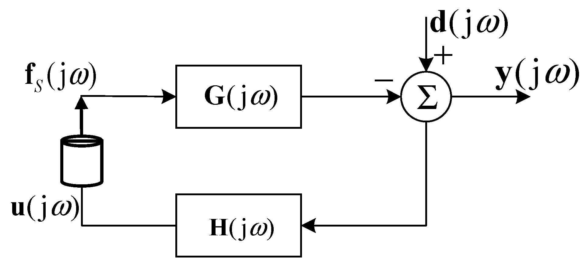
For the whole decentralized velocity feedback control system, one can assume that the square matrices of the plant and controller responses (the mobility matrix of the rib stiffened plate and the control gain matrix) are and , the closed-loop system can be illustrated by the block diagram in Figure 5.
Provided the control system is stable, the vector of the residual signals at the sensor outputs , i.e., the velocity vector , is related to the primary disturbance (the primary velocity vector at the location of the actuators ) by,
Then, the vector of control inputs to the actuators satisfies the following equation,
From Equation (15), the control input signal can be obtained and expressed as:
Substituting Equation (16) into Equation (13), the vector of the force produced by the S identical inertial actuators can be expressed as:
If we further define and , then the control force vector can be further expressed as:
Note that this set of control force is still correlated with the displacement of the rib stiffened plate on the location of the actuators. It is accessible that the control force produced by the inertial actuator is dependent on the relative displacement between the ribbed plate and the casing, as shown in Equation (7). Therefore, it can be considered that the control force vector is also coupled with the displacement of the ribbed plate. According to Equation (5), when this set of control force is added to the ribbed plate, the modal amplitudes of the base plate satisfy the following equation,
where ,,,… are the generalized modal force vectors, , and . is the location of theth inertial actuator. The vector of displacement on the location of the inertial actuators in Equation (18) can also be expressed as . Then, by substituting Equation (18) into Equation (19) one can obtain the following equation which the modal amplitudes of the base plate satisfy,
Therefore, the modal amplitudes of base plate in controlled condition can be obtained by,
Note that the control gains of the feedback loops have constant gains on each channel so that . Thus, given the panel responses and the feedback gain , the modal amplitudes vector can be obtained both in controlled and uncontrolled conditions. Then, the kinetic energy and the radiated sound power of the ribbed plate can be calculated.
3. Results and Discussion
3.1. Parameters of the Model
The parameters of the model used in simulation are listed in Table 1. The ribs are uniform beam elements with rectangular cross section. The geometrical sizes of the two ribs are the same to simplify the model. The primary excitation is the plane wave with amplitude Pa, incident at and . The structure damping is ignored in the modeling, thus a constant internal loss factor is introduced into the complex Young’s modulus as to make the simulation results more practical [14]. The properties of the inertial actuators used in this research are given in Table 2.
3.2. Active Control with Decentralized Velocity Feedback Controllers
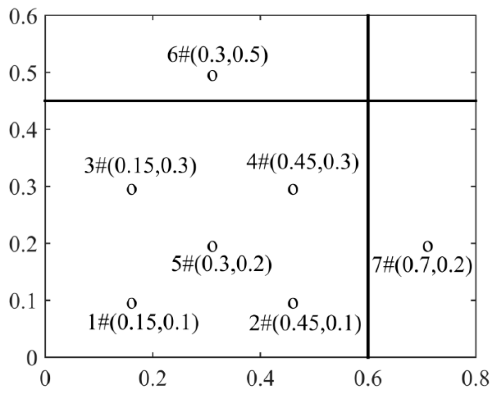
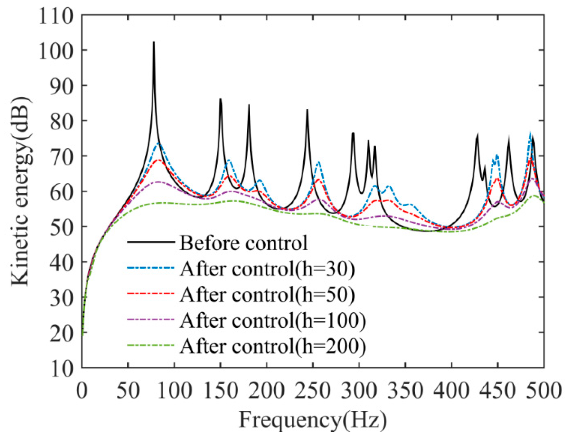
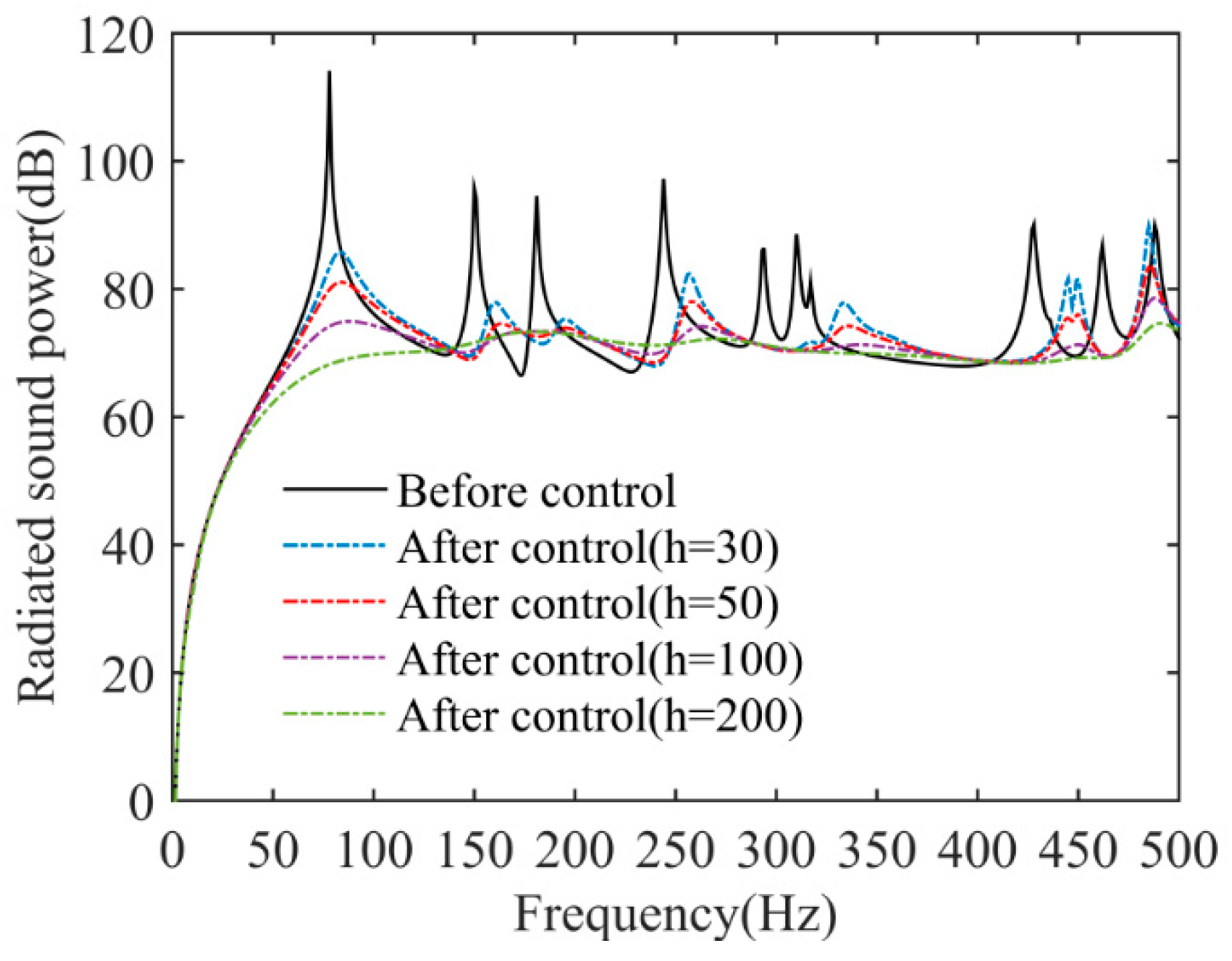
In this research, an upper limit of seven channel decentralized feedback controllers is considered. The locations and coordinates of these feedback loops are shown in Figure 6. The control performance of the seven channel feedback loops is validated when the control gain is set as 30, 50, 100, and 200. The kinetic energy and radiated sound power of the ribbed plate before and after control is calculated and plotted in Figure 7 and Figure 8. Note that the kinetic energy of the ribbed plate should be the sum of the kinetic energy of the base plate and the ribs. However, the quality of the base plate used in the simulation (5.4 kg) is much bigger than that of the two ribs (about 0.5 kg, less than one-tenth of the quality of the base plate). Hence, the kinetic energy of the ribbed plate is approximately obtained by calculating the kinetic energy of the base plate using the equation , which is expressed in dB with reference 1 × 10⁻¹². and are the density and thickness of the base plate, w is the displacement of the base plate at location . It can be found that the decentralized feedback controllers can effectively control the vibration and sound radiation of the orthogonally rib stiffened plate. Similar to the case of the unribbed plate—as the gains of the feedback loops are increased—the resonances in the response become more heavily damped. However, if the gains of the feedback loops are increased beyond a certain value, the active control effects will not further be improved remarkably.
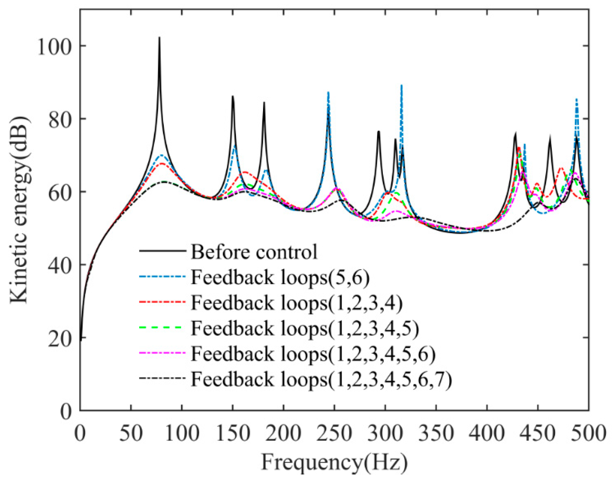
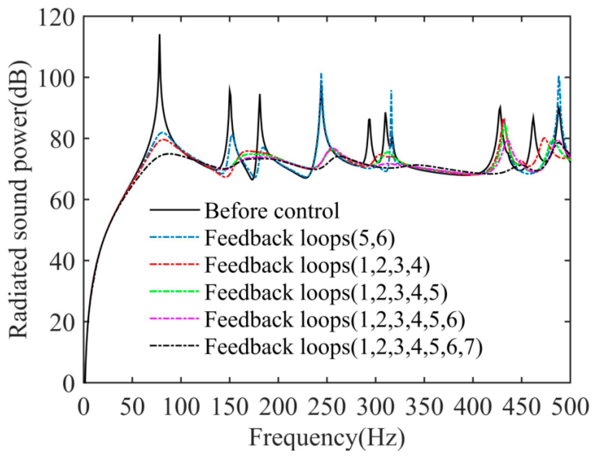
The decentralized systems with 2, 4, 5, 6, and 7 channel feedback loops are also examined to explore the impact of number of the feedback loops on the control results. The control gain is set as for these different cases. The kinetic energy and radiated sound power of the ribbed plate in controlled condition for each case with different number of feedback loops are calculated and plotted in Figure 9 and Figure 10. The active control result with two feedback loops (#5 and #6) is not very good, and there is even control spillover on some resonant frequencies. As the number of feedback loops increases, the active noise reduction may also slightly increases. However, too many feedback loops with tiny increment of noise reduction is meaningless for practical application. Hence, the number of the feedback loops should also be chosen appropriately.
4. Conclusions
This paper presents an analytical investigation on active control of sound radiation from the ribbed plate using decentralized velocity feedback controllers with inertial actuators. A simple modeling approach in frequency domain is proposed in this research to calculate the control performance of the decentralized system. A seven channel feedback loops is considered in the simulation to validate the availability of the model and the control effects of the system. Results obtained demonstrate that appropriately choosing the number of the decentralized unit and the feedback gain of each unit can achieve good control effects. Since the kinetic energy and radiated sound power of the ribbed plate have been significantly reduced under the control of seven feedback loops for this research (the magnitude of kinetic energy has been reduced to a very small level), it is predictable that too many decentralized units or very high feedback gains will not further substantially improve the active sound reduction. Existing literatures [20,27] have found that, for the ideal velocity-point force feedback loop (it is an ideal theoretical model where the velocity of the plate on the location of this loop is directly feedback into the controller, and then the control signal produced by the controller directly acts on the plate as the control force to control the vibration of this location), the system is unconditionally stable. However, for a physically realizable feedback loop—when the inertial actuator is applied to produce the control force—the system is conditionally stable because the dynamic characteristic of the inertial actuator is introduced into the closed loop [27]. Furthermore, for the ribbed plate, the vibration characteristic of the ribbed plate is more complicated, and the coupling effects of the ribs will also affect the stability of the system. This will be the ongoing work of this topic.
Author Contributions
Conceptualization, investigation, and writing—original draft preparation, X.M.; validation and formal analysis, L.W.; writing—review and editing, J.X.
Funding
This research was funded by the Fundamental Research Funds for the Central Universities (Grant No.3102017OQD005 and 3102019HHZY030025, the National Natural Science Foundation of China (NSFC, Grant No. 51705421), and the Research Funds of the Central Finance (Grant No. MJ-2015-F-044). The APC was funded by the National Natural Science Foundation of China (NSFC, Grant No. 51705421).
Conflicts of Interest
The authors declare no conflict of interest.
References
- Dozio, L.; Ricciardi, M. Free vibration analysis of ribbed plates by a combined analytical-numerical method. J. Sound Vib. 2009, 319, 681–697. [Google Scholar] [CrossRef]
- Gardonio, P.; Elliott, S.J. Active control of structure-borne and airborne sound transmission through double panel. J. Aircraft 1999, 36, 1023–1032. [Google Scholar] [CrossRef]
- Bravo, T.; Maury, C. Sound attenuation and absorption by micro-perforated panels backed by anisotropic fibrous materials: Theoretical and experimental study. J. Sound Vib. 2018, 425, 189–207. [Google Scholar] [CrossRef]
- Bravo, T.; Maury, C.; Pinhede, C. Sound absorption and transmission through flexible micro-perforated panels backed by an air layer and a thin plate. J. Acoust. Soc. Am. 2012, 131, 3853–3863. [Google Scholar] [CrossRef] [PubMed]
- Wang, C.; Huang, L. On the acoustic properties of parallel arrangement of multiple micro-perforated panel absorbers with different cavity depths. J. Acoust. Soc. Am. 2011, 130, 208–218. [Google Scholar] [CrossRef] [PubMed] [Green Version]
- Yang, C.; Li, D.; Cheng, L. Dynamic vibration absorbers for vibration control within a frequency band. J. Sound Vib. 2011, 330, 1582–1598. [Google Scholar] [CrossRef] [Green Version]
- Pietrzko, S.J.; Mao, Q. New results in active and passive control of sound transmission through double wall structures. Aerosp. Sci. Technol. 2008, 12, 42–53. [Google Scholar] [CrossRef]
- Sanada, A.; Tanaka, N. Theoretical and experimental study on active sound transmission control based on single structural mode actuation using point force actuators. J. Acoust. Soc. Am. 2012, 132, 767–778. [Google Scholar] [CrossRef]
- Aslani, P.; Sommerfeldt, S.D.; Blotter, J.D. Active control of simply supported cylindrical shells using the weighted sum of spatial gradients control metric. J. Acoust. Soc. Am. 2018, 143, 271–280. [Google Scholar] [CrossRef]
- Meymian, N.Z.; Clark, N.; Subramanian, J.; Heiskell, G.; Johnson, D.; Mahmudzadeh, F.; Darzi, M.; Musho, T.; Famouri, P. Quantification of windage and vibrational losses in flexure springs of a one kW two-stroke free piston liner engine alternator. SEA Tech. Pap. 2019. [Google Scholar] [CrossRef]
- Parkar, I.; Bayat, M. Analytical study on the non-liner vibration of Euler-Bernoulli beams. J. Vibroeng. 2012, 14, 216–224. [Google Scholar]
- Chang, Y.; Noormohamed, A.; Mercan, O. Analytical and experimental investigations of modified tuned liquid dampers. J. Sound Vib. 2018, 428, 179–194. [Google Scholar] [CrossRef]
- Mirafzal, S.H.; Khorasani, A.M.; Ghasemi, A.H. Optimizing time delay feedback for active vibration control of a cantilever beam using a genetic algorithm. J. Vib. Control 2016, 22, 4047–4061. [Google Scholar] [CrossRef]
- Pan, J.; Bao, C. Analytical study of different approaches for active control of sound transmission through double walls. J. Acoust. Soc. Am. 1998, 103, 1916–1922. [Google Scholar] [CrossRef]
- Bao, C.; Pan, J. Experimental study of different approaches for active control of sound transmission through double walls. J. Acoust. Soc. Am. 1997, 102, 1664–1670. [Google Scholar] [CrossRef]
- Ma, X.; Chen, K.; Ding, S.; Zhang, B. Some physical insights for active control of sound radiated from a clamped ribbed plate. Appl. Acoust. 2015, 99, 1–7. [Google Scholar] [CrossRef]
- Ma, X.; Chen, K.; Ding, S.; Yu, H. Physical mechanism of active control of sound transmission through rib stiffened double-panel structure. J. Sound Vib. 2016, 371, 2–18. [Google Scholar] [CrossRef]
- Charette, F.; Berry, A.; Guigou, C. Active control of sound radiation from a plate using a polyvinylidene fluoride volume displacement sensor. J. Acoust. Soc. Am. 1998, 103, 1493–1503. [Google Scholar] [CrossRef]
- Clark, R.L.; Fuller, C.R. Modal sensing of efficient acoustic radiators with polyvinylidene fluoride distributed sensors in active structural acoustic control approaches. J. Acoust. Soc. Am. 1992, 91, 3321–3329. [Google Scholar] [CrossRef]
- Elliott, S.J.; Gardonio, P.; Thomas, T.C.; Brennan, M.J. Active vibroacoustic control with multiple local feedback loops. J. Acoust. Soc. Am. 2002, 111, 908–915. [Google Scholar] [CrossRef]
- Gardonio, P.; Bianchi, E.; Elliott, S.J. Smart panel with multiple decentralized units for the control of sound transmission. Part I: Theoretical predictions. J. Sound Vib. 2004, 274, 163–192. [Google Scholar] [CrossRef]
- Gardonio, P.; Bianchi, E.; Elliott, S.J. Smart panel with multiple decentralized units for the control of sound transmission. Part II: Design of the decentralized control units. J. Sound Vib. 2004, 274, 193–213. [Google Scholar] [CrossRef]
- Bianchi, E.; Gardonio, P.; Elliott, S.J. Smart panel with multiple decentralized units for the control of sound transmission. Part III: Control system implementation. J. Sound Vib. 2004, 274, 215–232. [Google Scholar] [CrossRef]
- Aoki, Y.; Gardonio, P.G.; Elliott, S.J. Rectangular plate with velocity feedback loops using triangularly shaped piezoceramic actuators: Experimental control performance. J. Acoust. Soc. Am. 2008, 123, 1421–1426. [Google Scholar] [CrossRef] [PubMed]
- Díaz, C.G.; Paulitsch, C.; Gardonio, P. Active damping control unit using a small-scale proof mass electrodynamic actuator. J. Acoust. Soc. Am. 2008, 124, 886–897. [Google Scholar] [CrossRef]
- Díaz, C.G.; Paulitsch, C.; Gardonio, P. Smart panel with active damping units. Implementation of decentralized control. J. Acoust. Soc. Am. 2008, 124, 898–910. [Google Scholar] [CrossRef] [PubMed]
- Baumann, O.N.; Elliot, S.J. The stability of decentralized multichannel velocity feedback controllers using inertial actuators. J. Acoust. Soc. Am. 2007, 121, 188–196. [Google Scholar] [CrossRef]
- Carneal, J.P.; Fuller, C.R. An analytical and experimental investigation of active structural acoustic control of noise transmission through double panel systems. J. Sound Vib. 2004, 272, 749–771. [Google Scholar] [CrossRef]
- Lin, T.; Pan, J. A closed form solution for the dynamic response of finite ribbed plates. J. Acoust. Soc. Am. 2006, 119, 917–925. [Google Scholar] [CrossRef]
Figure 1.
Systemic model: (a) active orthogonally rib stiffened plate; (b) the coupling effects between the base plate and the rib for the vertical rib; (c) the coupling effects for the horizontal rib.
Figure 1.
Systemic model: (a) active orthogonally rib stiffened plate; (b) the coupling effects between the base plate and the rib for the vertical rib; (c) the coupling effects for the horizontal rib.

Figure 2.
The sketch of the decentralized system.

Figure 3.
The arrangement of the feedback loops.

Figure 4.
Schematic of the inertial actuator. (a) Schematic of a concept inertial actuator; (b) inertial actuator model.
Figure 4.
Schematic of the inertial actuator. (a) Schematic of a concept inertial actuator; (b) inertial actuator model.

Figure 5.
The block diagram of the closed-loop system.

Figure 6.
The locations and coordinates of the feedback loops.

Figure 7.
The kinetic energy of the ribbed plate before and after control using seven feedback loops with different control gain.
Figure 7.
The kinetic energy of the ribbed plate before and after control using seven feedback loops with different control gain.

Figure 8.
The radiated sound power of the ribbed plate before and after control using seven feedback loops with different control gain.
Figure 8.
The radiated sound power of the ribbed plate before and after control using seven feedback loops with different control gain.

Figure 9.
The kinetic energy of the ribbed plate before and after control with different number of feedback loops.
Figure 9.
The kinetic energy of the ribbed plate before and after control with different number of feedback loops.

Figure 10.
The radiated sound power of the ribbed plate before and after control with different number of feedback loops.
Figure 10.
The radiated sound power of the ribbed plate before and after control with different number of feedback loops.


Table 1.
The parameters of the model.
| Geometrical Parameters | Value | Material Properties | Value |
|---|---|---|---|
| The length and width of the base plate | m m | The material of the base plate and the ribs | aluminum |
| The thickness of the base plate | m | The density of aluminum | kg/m3 |
| The locations of the vertical and horizontal ribs | 0.6 m 0.45 m | The Young’s modulus of aluminum | N/m2 |
| The size of the rectangular cross section of the ribs (wide × high) | m2 | The Poisson’s ratio of aluminum | |
| The primary excitation | Pa | The density of air | kg/m3 |
| The sound speed of air | m/s |
Table 2.
The properties of the actuator.
| Property | Value |
|---|---|
© 2019 by the authors. Licensee MDPI, Basel, Switzerland. This article is an open access article distributed under the terms and conditions of the Creative Commons Attribution (CC BY) license (http://creativecommons.org/licenses/by/4.0/).
Share and Cite
MDPI and ACS Style
Ma, X.; Wang, L.; Xu, J. Active Vibration Control of Rib Stiffened Plate by Using Decentralized Velocity Feedback Controllers with Inertial Actuators. Appl. Sci. 2019, 9, 3188. https://0-doi-org.brum.beds.ac.uk/10.3390/app9153188
AMA Style
Ma X, Wang L, Xu J. Active Vibration Control of Rib Stiffened Plate by Using Decentralized Velocity Feedback Controllers with Inertial Actuators. Applied Sciences. 2019; 9(15):3188. https://0-doi-org.brum.beds.ac.uk/10.3390/app9153188
Chicago/Turabian StyleMa, Xiyue, Lei Wang, and Jian Xu. 2019. "Active Vibration Control of Rib Stiffened Plate by Using Decentralized Velocity Feedback Controllers with Inertial Actuators" Applied Sciences 9, no. 15: 3188. https://0-doi-org.brum.beds.ac.uk/10.3390/app9153188
Note that from the first issue of 2016, this journal uses article numbers instead of page numbers. See further details here.