Materials Have Driven the Historical Development of the Tennis Racket
by
 ,
,
Luca Taraborrelli
1,*, 
Robyn Grant
2,
Matthew Sullivan
2,
Simon Choppin
3,
James Spurr
4,
Steve Haake
3 and
Tom Allen
1,*
1
Department of Engineering, Manchester Metropolitan University, London N7 8DB, UK
2
Department of Natural Sciences, Manchester Metropolitan University, London N7 8DB, UK
3
Centre for Sports Engineering Research, Sheffield Hallam University, Sheffield S1 1WB, UK
4
The International Tennis Federation, London SW15 5XZ, UK
*
Authors to whom correspondence should be addressed.
Appl. Sci. 2019, 9(20), 4352; https://0-doi-org.brum.beds.ac.uk/10.3390/app9204352
Submission received: 18 September 2019
/
Revised: 4 October 2019
/
Accepted: 6 October 2019
/
Published: 17 October 2019
(This article belongs to the Collection Sports Equipment and Materials)
Abstract
:The tennis racket has developed since the origins of Lawn Tennis in the 1870s. This study investigated how the tennis racket developed from 1874 to 2017, using measurements and material classifications for 525 samples. Racket measurements covered geometric, inertial and dynamic properties, and the number of strings. Rackets predating 1970 were mainly wooden, and typically characterised by head areas below 0.05 m2, masses over 350 g and natural frequencies below 120 Hz. Rackets from the 1970s were made from wood, metal and fibre–polymer composites, with most postdating 1980 made from fibre–polymer composites with a larger head, lower mass and higher natural frequency than their predecessors. Principal component analysis was used to reduce the dimensionality of the number of variables. Principal component one (PCA1) accounted for 35% of the variance in the measured racket properties, and was found to be significantly affected by material. Head width was best correlated with principal component one (r = 0.897, p < 0.001), followed by head length (r = 0.841, p < 0.001) and natural frequency (r = 0.813, p < 0.001). Early rackets were constrained by the limitations of wood, and the move to composites, which began in the 1970s, allowed this observed increase in head size and natural frequency. As material development has been a major driver of racket design in the past, we propose that new materials and manufacturing techniques, like additively manufactured composites, could further improve the tennis racket. The measurement techniques described here can be used to monitor developments in racket design.
1. Introduction
Lawn Tennis (tennis) is widely considered to have been ‘invented’ in 1874, when Major Wingfield patented the game and started marketing sets for playing on suitable grass [1]. Early tennis rackets were similar to those used in Real Tennis, and were typically asymmetrical or ‘lopsided’ [2]. The ball bounces low in Real Tennis, and a racket with a lopsided head is desirable to make it easier to bring the hitting surface close to the ground. These lopsided rackets disappeared from tennis as the game developed, with symmetrical frames common by the end of the nineteenth century. Most early tennis rackets were wooden, with incremental developments until the 1960s [2,3,4]. Tennis became more competitive with the introduction of the Open Era in 1968, when professionals and amateurs started competing together for prize money. In 1968, the Wimbledon Championships prize money for Gentlemen’s Singles and Ladies’ Singles winners were £2000 and £750 (~£30 k and £11 k value today), respectively, compared to over two million in 2019 [5]. Increased competition, larger prize funds and demand from players helped drive the development of the tennis racket. With better rackets, tennis developed from a game of serve-and-volley to baseline play, with the fastest male and female servers exceeding ball speeds of 55 m/s (>200 km/h).
Engineers explored aluminium and fibre–polymer composites as alternatives to wood in the 1970s, as they experimented with new racket shapes [2,3,4]. In 1976, Howard Head patented a frame with an ‘oversized head’ [6] that made it easier to play and laid foundations for the modern racket. In response to these developments, the International Tennis Federation (ITF) began specifying rules for the racket in 1978, to protect the nature of the game and ensure that the player was the primary determinant of a match outcome. Racket size was first limited in 1981, with current limits of 737 mm for overall length, 292 mm for width, and 394 mm for hitting surface length [7]. Most modern rackets are now made from fibre–polymer composites, which offer high specific modulus and manufacturing versatility, providing the engineer with more freedom over parameters such as the mass distribution and stiffness [4].
There are many publications on the mechanics of tennis and the role of the racket (e.g., [8,9,10,11,12,13,14,15]), with reviews highlighting the importance of considering player-racket interactions [16,17]. Racket inertial properties are particularly important, as they influence the player’s ability to accelerate the racket through the stroke [18,19,20,21]. A better knowledge of how the racket has developed over time could improve our understanding of its contribution to player performance, with implications for product development and regulation [7], injury prevention strategies [9,22,23], and exercise promotion initiatives [24], as well as spectator experience, and education purposes [25,26,27]. Haake et al. [3] published the most comprehensive work to date on the historical development of the tennis racket, by characterising 150 rackets from the 1870s to 2007 and illustrating how their dimensions, inertial properties and natural frequencies have changed. This work goes further than Haake et al. [3], by undertaking a wider range of measurements on a larger and more diverse group of racket dating from 1874 to 2017, while also reporting on materials.
2. Materials and Methods
Data from 525 rackets from 1874 to 2017 were collected and recorded in Excel® (Microsoft, Redmond, WA, USA) (see Table S1 in the Supplementary Material) and analysed in MATLAB® (Matworks, Natick, MA, USA). One hundred and eight rackets were characterised at the Wimbledon Lawn Tennis Museum, where it was possible to access old, rare and valuable samples, and one was from Manchester Metropolitan University. Measurements (and other records) of the other 416 rackets came from prior work [28,29]. Of the 525 rackets, 417 (79.5%) were from the museum, 91 (17%) were from a brand’s headquarters [28], 13 (2.5%) were from the university and four (1%) were from the ITF.
Racket dating was principally carried out using a book [2] and the museum catalogue. If a racket featured in the book [2] and a range of less than ten years was given (135 (26%) rackets), the earliest date (year of release) was used. In 323 (62%) cases, dating was carried out using the museum catalogue, mainly (282 cases) because the racket was not in the book [2]. For racket models that were manufactured for more than nine years (17 models (e.g., Demon, Slazenger; Tournament, Spalding; Maxply, Dunlop) and 41 (8%) rackets), dates were taken from the catalogue to give the best estimation of the sample, as the design may have changed over time. The book [2] did not include rackets postdating 1990, and dates for 67 (13%) rackets (from the work reported in [28]) were obtained by consulting the manufacturer and websites [30,31]. Some rackets may have been dated incorrectly (the catalogue stated “circa” before the date for 271 (52%) of the rackets), with errors estimated to be within five years in most instances, which was deemed acceptable given that >500 rackets spanning >140 years were characterised.
Visual inspection identified racket materials, with cross checking against the book [2], catalogue, websites and graphics. No distinction was made between types of wood (ash, maple, mahogany, beech etc.), grades of metal nor the constituent materials of a fibre–polymer composite (epoxy, glass, graphene, carbon, aramid etc.), with rackets categorised as either, wood, steel, aluminium or composite, or a combination of two of these. Based on recommendations from previous work [28], string materials were not considered as it is challenging to identify them from visual inspection and the original strings may have been replaced.
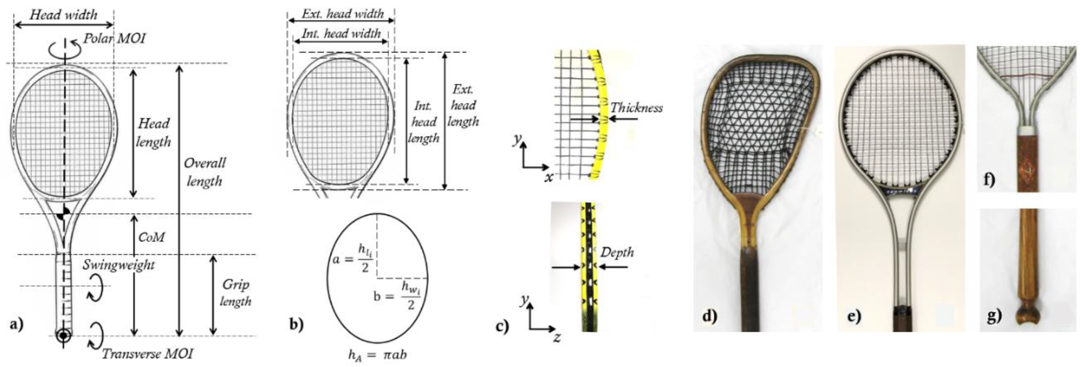
Figure 1a–c defines the racket measurements and Table 1 summarises the methods, which are detailed in [29]. Each racket was photographed, as were any distinguishing features (Figure 1d–g) (relative to a conventional modern racket) such as holes in the frame, extended string bed/no yoke, asymmetry, adjustable string patterns and unconventional yokes/throat regions. These distinguishing features were grouped in four categories: Head features, throat features, handle features and stringing patterns. For older rackets with wooden handles, grip length was identified using any grooves or engravings, a different wood/colour or polished coverings on the handle, as illustrated in [29]. A scale (Smart Weigh SWS1KG Elite Series) and support were used to locate the racket’s centre of mass (CoM) [29]. The racket was held horizontal with one end on the scale and the other the support, with the CoM location obtained from the product of its length and the ratio of the scale reading to the total mass. The method was compared to the more common approach of locating the ‘balance point’ for five rackets (1932 to 1987 with CoM locations from 321 to 335 mm), whereby the racket is balanced on a narrow support under the CoM [3,28]: the largest difference between the two methods was 2 mm (<1%).
Racket frame depth (Figure 1c) was estimated as the mean of the minimum and maximum depth measurements. Racket frame thickness (Figure 1c) was estimated as half the difference between the external and internal head width (Figure 1b). Head length was not used to estimate frame thickness, because some rackets (e.g., Dayton Steel Racket Corporation) had no yoke with strings connected to the handle. Racket head area (ha) was approximated as an ellipse (Figure 1b) using Equation (1),
where is the internal head length. To account for changes in head size when investigating the number of strings, string bed density (sd) was calculated using Equation (2).
where and are the number of cross and main strings, respectively.
Transverse moment of inertia (MOI) was defined as the MOI acting about a lateral in-plane axis passing through the butt (Figure 1a), which gives higher values than taking MOI about the lateral in-plane axis passing through the CoM. The parallel axis theorem can be applied to calculate MOI about the lateral in-plane axis at any location along the length of the frame, using the values provided in Table S1 in the Supplementary Material (e.g., for obtaining ‘swingweight’ as defined Figure 1a). Polar MOI, or ‘twistweight’, is the MOI acting about the longitudinal axis of the racket (Figure 1a). Transverse and Polar moments of inertia were estimated using models from [29], with a Polar MOI model that estimates the racket head as a circle selected for its simplicity. The Polar MOI model could not be used for the 23 (4%) lopsided (or asymmetric) frames. Measured MOIs for the 416 (79.5%) rackets from previous work [28,29] were plotted against date alongside the estimated values, to check the models gave the correct trends over time.
The frequency and damping ratio () of the first mode of each racket were obtained from modal analysis. The racket was suspended by a long string with a single axis accelerometer (TE Connectivity Model 805) strapped to the handle (antinode), and the string-bed was struck lightly on the longitudinal axis away from the node with a ball to excite vibrations. The accelerometer was connected via a signal conditioner (PCB Model 480E09) to a digital oscilloscope (PicoScope 2000 Series), and then to a computer where vibrations could be viewed live and natural frequencies (i.e., fundamental mode of the freely suspended racket) obtained using the oscilloscope software (Picosope 6). The accelerometer sampled at 3 kHz and recorded for 5 s with the trigger located at 10% of the time window, giving a frequency resolution of 0.2 Hz. The vibration signals for the 91 (17%) rackets characterised previously at the brand were obtained using a wireless accelerometer (MetaWear CPro, Mbientlab Inc) sampling at 800 Hz, as described in [28]. A check using a racket model (Ti.S6, HEAD) located within both the brand and museum confirmed that the two accelerometers gave the same result for natural frequency (176 Hz).
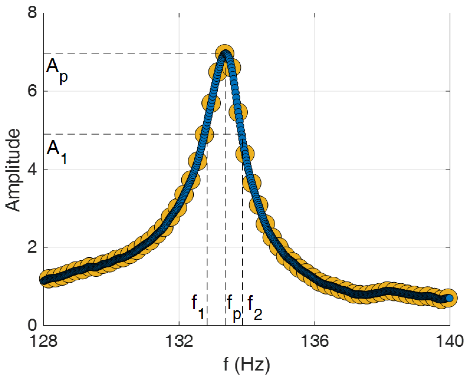
The recorded signals for all rackets were post-processed in MATLAB® to identify the natural frequency and damping ratio. The script performed a Fourier transform of the signal with the MATLAB® function fft, and the first peak in the power spectrum (fp) was assigned to the natural frequency of the racket. Similar to [28], the wired accelerometer was calibrated using a shaker excited at frequencies of 100, 150 and 200 Hz. Each calibration test was repeated three times, with the frequency from the accelerometer always matching the excitation value. Damping ratio was calculated with the half-power bandwidth method (Figure 2), as commonly used for estimating damping in multi-DOF systems [32]. The method first involves identifying the two half-power frequencies (f1 and f2), which are located either side of the peak frequency were the amplitude (A1) is equal to the amplitude at the peak (Ap) divided by √2 (i.e., ). The half-power damping ratio can then be obtained using Equation (3),
where is the frequency range. The number of data points in the region of the power spectrum that corresponds to the natural frequency (± 10 Hz of fp) was increased using a spline function in MATLAB®, to improve the frequency resolution (0.02 Hz) and the accuracy of the damping estimation, as shown in Figure 2. When applying the half-power bandwidth method, for a given natural frequency, damping ratio will increase with the frequency range (wider and less pronounced peak), while for a given frequency range, damping ratio will increase as natural frequency decreases. Each racket was tested twice, with the mean natural frequency (to 1 Hz) and damping ratio reported. The uncertainty in the calculation of damping ratio was dependent on both the damping ratio and natural frequency of the racket, as outlined in Equation (4),
For example, the uncertainty in damping ratio for a wooden racket with a natural frequency of 100 Hz and damping ratio 1% would be 2.2% of the calculated value. Four hundred and ninety-four (94%) rackets had an uncertainty in damping ratio below 5%, 28 (4%) rackets had an uncertainty between 5 and 10%, and 3 (<1%) rackets had an uncertainty between 10 and 15%. The highest uncertainty in damping ratio was associated with metal rackets, because they have both low frequency and low damping.
The resistance of a racket to bending can be increased using stiffer materials or larger cross sections. Fibre–polymer composites allow for rackets with large hollow cross sections, combining a high second moment of area with low mass. Measuring the cross section of hollow rackets was not possible without cutting them or taking them to a three-dimensional imaging device, such as a computed tomography scanner, so the ratio of the frame depth to thickness was used as a proxy for the second moment of area. The natural frequency of a freely suspended racket is often used as an analogue to its stiffness [33], although it is also affected by mass [34].
To reduce the dimensionality of the number of measured variables, a principal component analysis (PCA) [35] was conducted for all racket frame measurements (racket, head (int.) and grip length, racket width (int.), frame thickness and depth, frequency and damping, mass, CoM location, and transverse and polar MOI). The three principal components that accounted for the most variance in the measured variables were then further analysed. Firstly, they were examined to see if they varied between material or brand (only including the 12 brands that were represented by at least six rackets, equating to 271 (52%) samples). Material and brand were introduced as between-factors in a multivariate ANOVA, with PCA1, PCA2 and PCA3 as the dependent variables. Partial eta squared (ηp2) was also used to quantify the effect sizes of these analyses, where ηp2 > 0.01 is a small effect, ηp2 > 0.06 is a medium effect and ηp2 > 0.14 is a large effect [36]. A bivariate Pearson’s correlation was conducted on PCA1 and PCA2 to see which of the measured variables were best correlated to them, in terms of their correlation coefficients, and the variables where r > 0.7 are presented.
In most instances, the measured parameters were plotted against date with a data point for each racket colour coded for the material categorisation. A moving average of the data was calculated in MATLAB®, using the smooth function (moving average filter) and setting a method (rloess) that assigns lower weight to any outliers, and plotted as a trend line. A moving standard deviation over 50 consecutive points was calculated using the movstd MATLAB® function, and was shown in the background of the graphs shaded green.
3. Results
3.1. Geometric Properties
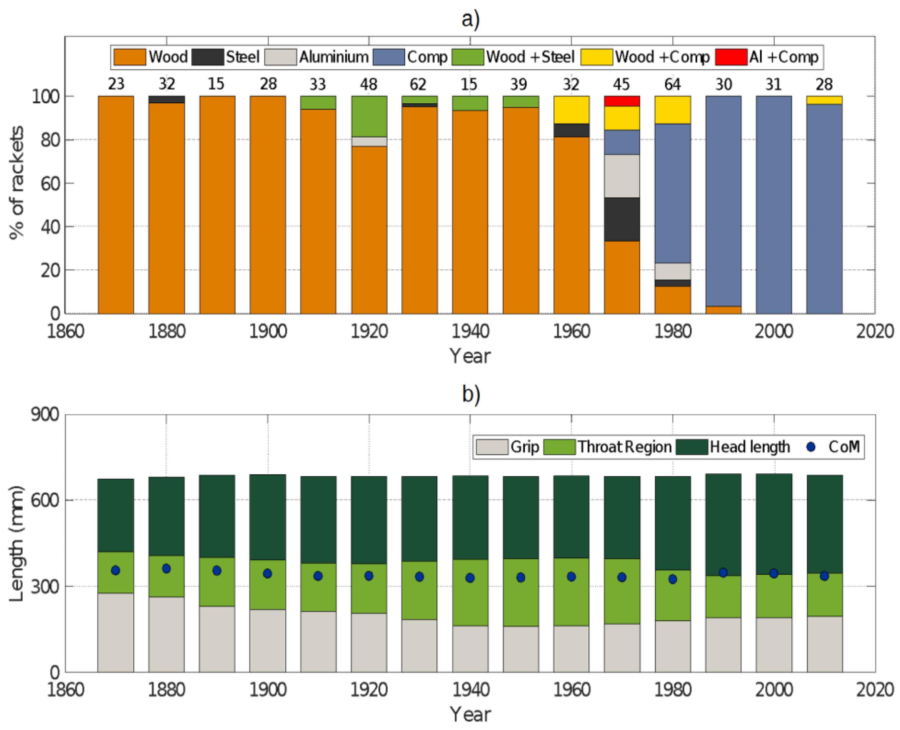
Figure 3 summarises how the frame materials (Figure 3b) and lengths (Figure 3a) of the racket, grip, throat region and head (ext.), and CoM location, changed over time. Wood was the common material until the 1960s, although there were also twenty metal rackets in our sample from this time (2 steel, 2 aluminium, 16 wood + steel). The first example of a steel racket was from 1887 (Metallic Racquet Corporation, Aberdeen), with an aluminium example from the 1920s (Birmal, Birmingham Aluminium Casting Limited). Following a small increase over the first few decades, the length of the rackets barely changed (mean (μ) ± standard deviation (σ), 0.69 ± 0.01 m), possibly due to the limit introduced by the ITF in 1981. The CoM of the rackets moved towards the handle from the 1870s to the 1980s, and then back towards the tip with the move to composites (μ ± σ, 0.34 ± 0.02 m). The COM moved from the throat region into the head during the 1990s as a response to the introduction of oversize rackets (one of the key claims of Howard Head’s racket patent [6]). The rackets predating 1890 had long grips, limited throat regions and short heads. The head length of the rackets barely changed from the 1890s to the 1970s, as throat regions lengthened and grips shortened. Composites first occurred in the rackets from the 1960s (wood + comp.), mainly as reinforcement on a wooden frame (e.g., “Fibre Armoured” on 1961 Challenge Power, Slazenger; “Fibre Face” on 1966 Kramer Cup, Wilson), with wood remaining as the common material. The first examples of entirely composite rackets were from the 1970s (Phantom, Slazenger, 1974; TR10, Rossignol, 1977; make and model unknown, WTM 1995/136, 1970s). Two rackets from the 1970s had a composite core sandwiched between aluminium plates (Arthur Ashe and Drive, Head). Wooden rackets made up around a third of those from the 1970s, and there were still examples of composite reinforced wooden frames. The number of composite (64%) rackets increased in the 1980s, as the proportion of wooden (13%) and metal (11%) rackets declined. Rackets from the 1980s had longer heads and shorter throat regions than those from the 1970s. Head and grip lengths increased further in the rackets from the 1990s, with little change over the last three decades, with all but two being composite. Only one racket from 2011 had a wooden “spine” in a composite frame (Core 1 Number 20, Pro-Kennex), with claims that it benefitted from the damping properties of wood.
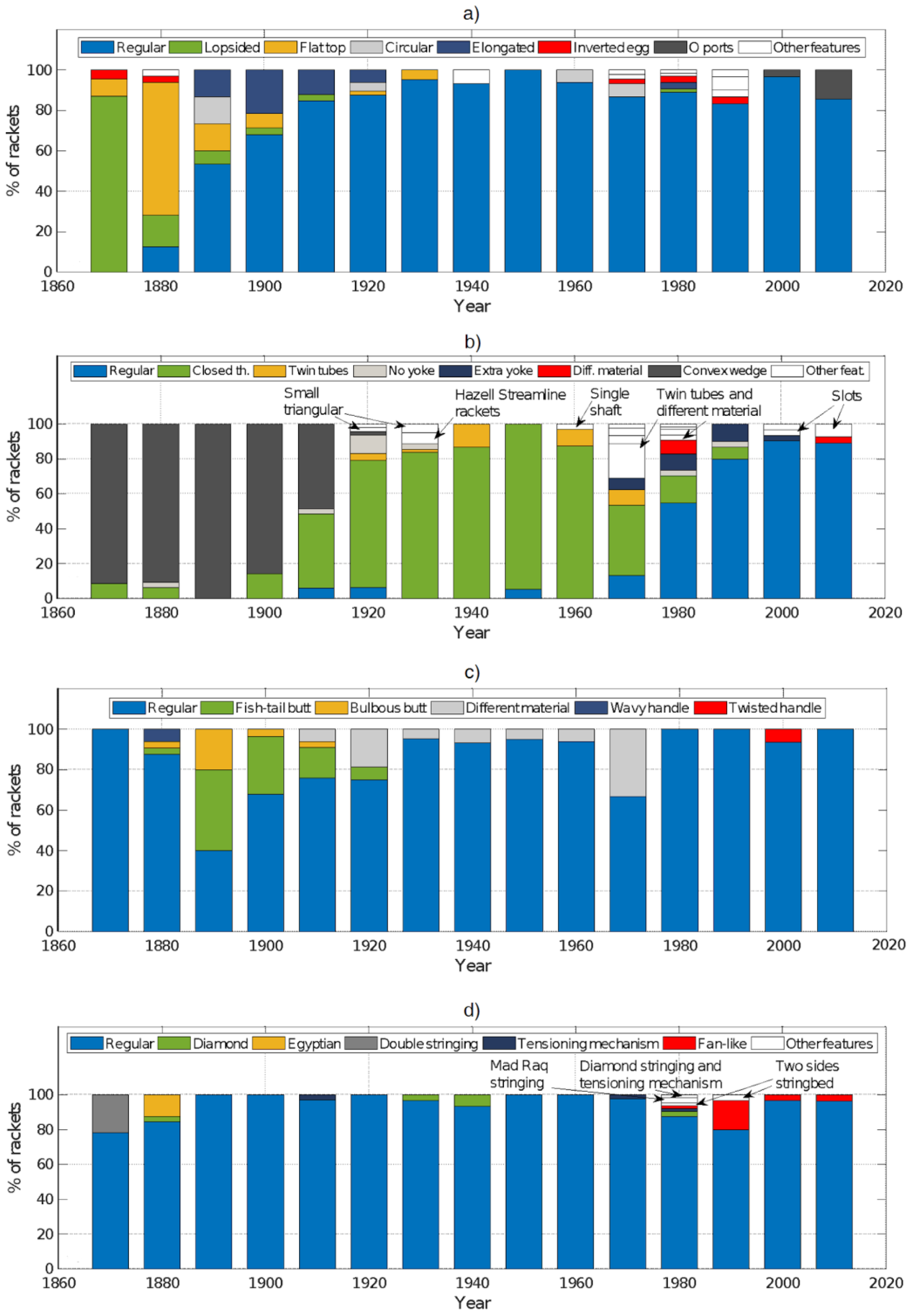
Figure 4a shows the oldest rackets typically had lopsided or other unconventionally-shaped heads, with most samples postdating 1890 having ‘regular’ elliptical heads. Figure 4b shows that the rackets predating 1920 typically had convex wedge-shaped throats, those dating from 1920 to 1980 typically had closed throats and those postdating 1980, which were mainly composite, typically had ‘regular’ open throats. Figure 4c shows that most of the rackets had a ‘regular’ shaped handle, although some of the older samples had more ornate handle shapes and a small portion from 1910 to 1980 had a handle made from a different material to the rest of the frame. Figure 4d shows that the vast majority of the rackets had ‘regular’ stringing patterns, with some examples of less conventional patterns.
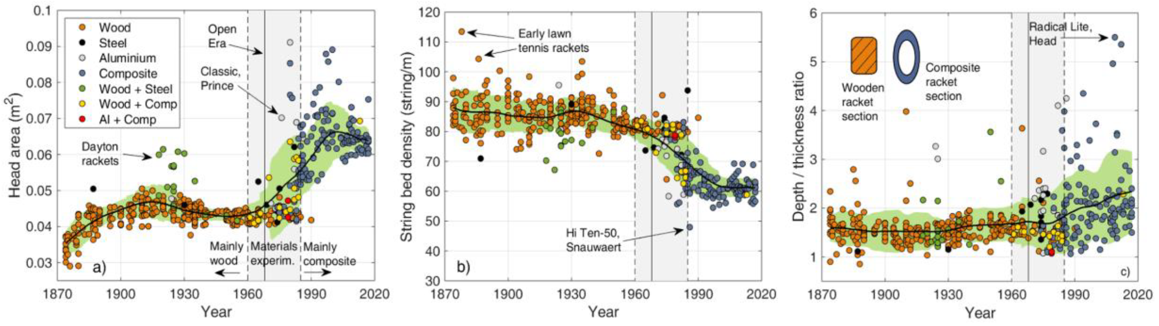
Figure 5 summarises how the head area, the string bed density and the depth to thickness ratio of the rackets changed over time. Figure 5a shows head area increased in the 1970s with material experimentation. The aluminium racket with a large head area (0.0702 m2) from 1976 was Howard Head’s ‘oversize’ design (Classic, Prince), following which there was an increase in the head area of the rackets (~0.045 to ~0.07 m2) coinciding with the move to composites. The collection of outlying green dots around the 1930s in Figure 5a represent rackets with a metal frame, which often had long heads and strings that extended to the handle (therefore head area may have been overestimated by assuming that the head is an ellipse). String bed density was almost constant before 1960 at ~85 strings/m, although some of the early rackets had densities exceeding 100 strings/m, as they had small heads and many (>45), narrowly-spaced strings (Figure 5b). String bed densities decreased to ~60 strings/m after 1980, with the move to rackets with larger heads. Figure 5c shows that from the 1870s to 1970, when most of the rackets were wooden with solid cross-sections, the ratio of frame depth to thickness was almost constant at ~1.6 (~12 mm frame thickness). After 1970, frame depth to width ratio steadily increased to about two (mainly due to an increase in frame depth from ~21 to ~25 mm), with ratios exceeding three in some rackets. Clear increases in frame to depth ratios followed the introduction of ‘widebody’ rackets in the late 1980s. These ‘widebody’ rackets have greater depth around the middle of the frame than at the handle and tip, providing the highest stiffness in the region of maximum bending [4,37]. The results indicate that composite rackets have more diverse cross-section shapes than their wooden predecessors.
3.2. Inertial properties
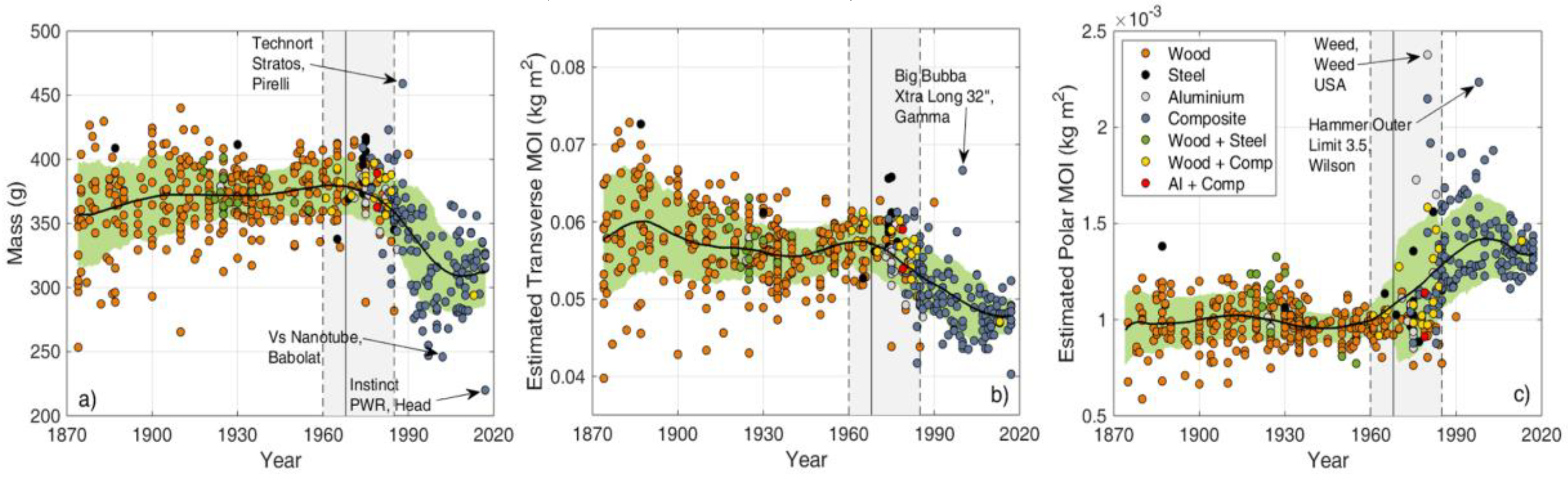
Figure 6a shows that the mean mass of the rackets remained almost constant from the 1870s to 1970, but the data points were scattered (μ ± σ, 370 ± 27 g). Mass dropped after 1980, and the composite rackets weighed ~40 g less than their wooden predecessors, with more variation (μ ± σ, 330 ± 40 g). The heaviest racket (Technort Stratos, Pirelli) had a ‘shock-absorption’ device in the handle. Figure 6b shows that Transverse MOI gradually decreased until the 1960s, which may have been due to the marginal shift of the CoM towards the handle (Figure 3a) [29] (as mass barely changed). Transverse MOI increased slightly after 1970s, most likely because the steel rackets tended to be heavier (Figure 6a) [29]. From the 1980s, Transverse MOI of the rackets dropped from ~0.057 to ~0.047 kgm2, mimicking the trend of mass [29]. Polar MOI (Figure 6c) showed little change until 1960 and then increased with the move to rackets with wider heads [29,38]. The racket with the widest head (Weed, with an illegal head width) had the highest Polar MOI (as found by [38]), while the lowest values were for narrow early tennis rackets (Figure 5a).
3.3. Dynamic Properties
Figure 7a shows that natural frequencies for the wooden rackets typically fell between 80 and 120 Hz (μ ± σ, 99.4 ± 9.7 Hz). Natural frequencies increased to >120 Hz and became more varied (μ ± σ, 143 ± 27 Hz) with the move to composite rackets coinciding with deep frames (Figure 5c) and low mass (Figure 7a). Clear increases in natural frequency followed the introduction of ‘widebody’ rackets in the late 1980s. Figure 7b shows the wooden rackets tended to have the highest damping (~1.2%), followed by the composite (~0.6%) and metal rackets (~0.4%), in line with the known properties of these materials [39]. Figure 7c shows damping ratio vs. natural frequency and demonstrates that the rackets cluster by material. A low frequency and high damping cluster was formed of wooden rackets, a low frequency and low damping cluster was formed of metal rackets and a high frequency and low damping cluster was formed of composite rackets. Figure 7d shows vibration signals for three rackets. The metal racket had low-damped vibrations that lasted for a few seconds, while vibrations of the wooden racket only lasted for around half a second, due to its higher damping. Despite having low damping like the metal racket, the vibrations of the composite racket only lasted for about a second because they had a shorter wavelength (due to the higher natural frequency).
3.4. Principal Component Analysis and Summary
The PCA conducted on all the racket variables reported that PCA1 accounted for 35% of the variance of the data, PCA2 for 17% and PCA3 for 12%. These three principal components were investigated further to see if they varied with material or brand. Material significantly affected PCA1 (Between-ANOVA: F (6525) = 17.813, p < 0.001), with a large effect size (ηp2 = 0.181); brand also affected PCA1 with a medium effect size (Between-ANOVA: F (13,525) = 3.919, p < 0.001, ηp2 = 0.095). Material did not significantly affect PCA2, but brand did, with a medium effect size (Between-ANOVA: F (13,525) = 4.266, p < 0.001, ηp2 = 0.103). Neither material nor brand had a significant effect on PCA3.
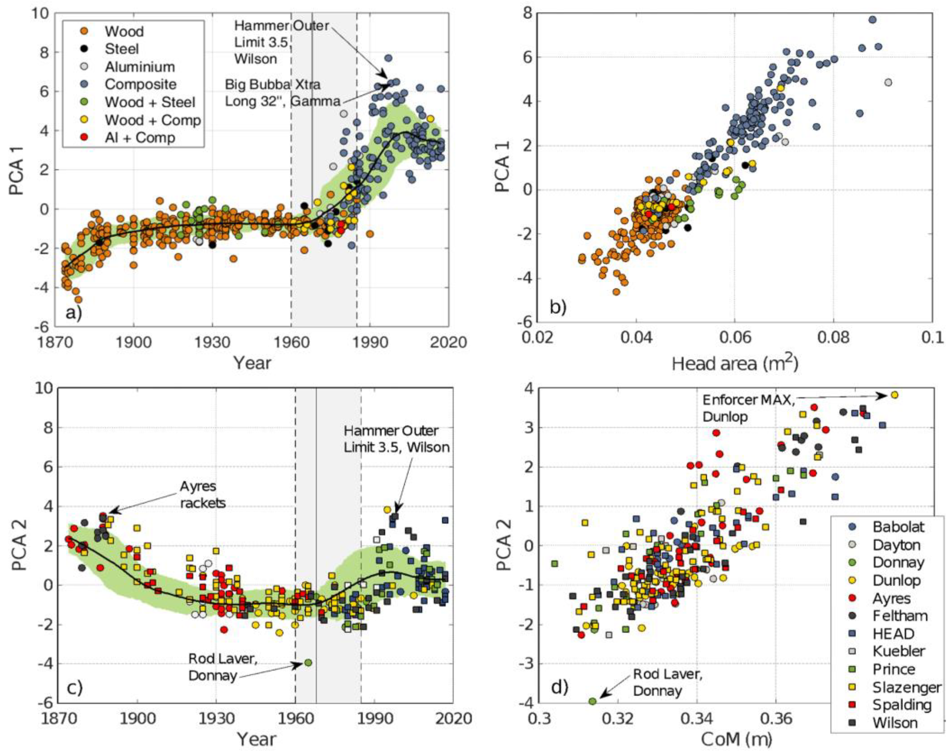
Figure 8a shows PCA1 to increase with year, particularly with the introduction of aluminium and composite rackets with more varied PCA1 values. When a bivariate Pearson’s correlation was conducted on all the racket variables with PCA1, head width had the best correlation (r = 0.897, p < 0.001), followed by head length (r = 0.841, p < 0.001). Indeed, Figure 8a for PCA 1 vs. year has a similar shape to Figure 5a for head area vs. year. Figure 8b shows head area vs. PCA1, with large headed composite rackets having higher and more varied PCA1 values than their wooden predecessors. Therefore, the largest variation in the rackets, captured by PCA1, could be explained by differences in head area. Natural frequency was also well-correlated to PCA1 (r = 0.813, p < 0.001), as the composite rackets had higher natural frequencies (Figure 7a). Figure 8a for PCA1 vs. year also has a similar shape to Figure 7a for natural frequency vs. year.
Figure 8c shows PCA2 to be larger in older and newer rackets (1870s and 1990s), and smaller from 1930 to 1960. This trend of PCA2 vs. year is also similar to that for CoM location (Figure 3b) and grip length (Figure 3b). When a bivariate Pearson’s correlation was conducted on all the racket variables with PCA2, CoM location had the largest correlation coefficient (r = 0.854, p < 0.001), followed by grip length (r = 0.745, p < 0.001). PCA2 could, therefore, be explained by differences in CoM location, as well as grip length. Figure 8d shows rackets with a CoM closer to tip tended to have higher PCA2 values. PCA2 values for brands that were well represented, with many rackets spanning a range of dates (e.g., Spalding, Wilson, HEAD, Prince, Dunlop Slazenger and Donnay), tended to change over time with the trend of the racket population. The medium effect of brand on PCA2 and PCA1 may, therefore, have been due to differences in the ages of the rackets between brands (e.g., Feltham and Babolat), rather than differences in racket parameters between brands at a given time.
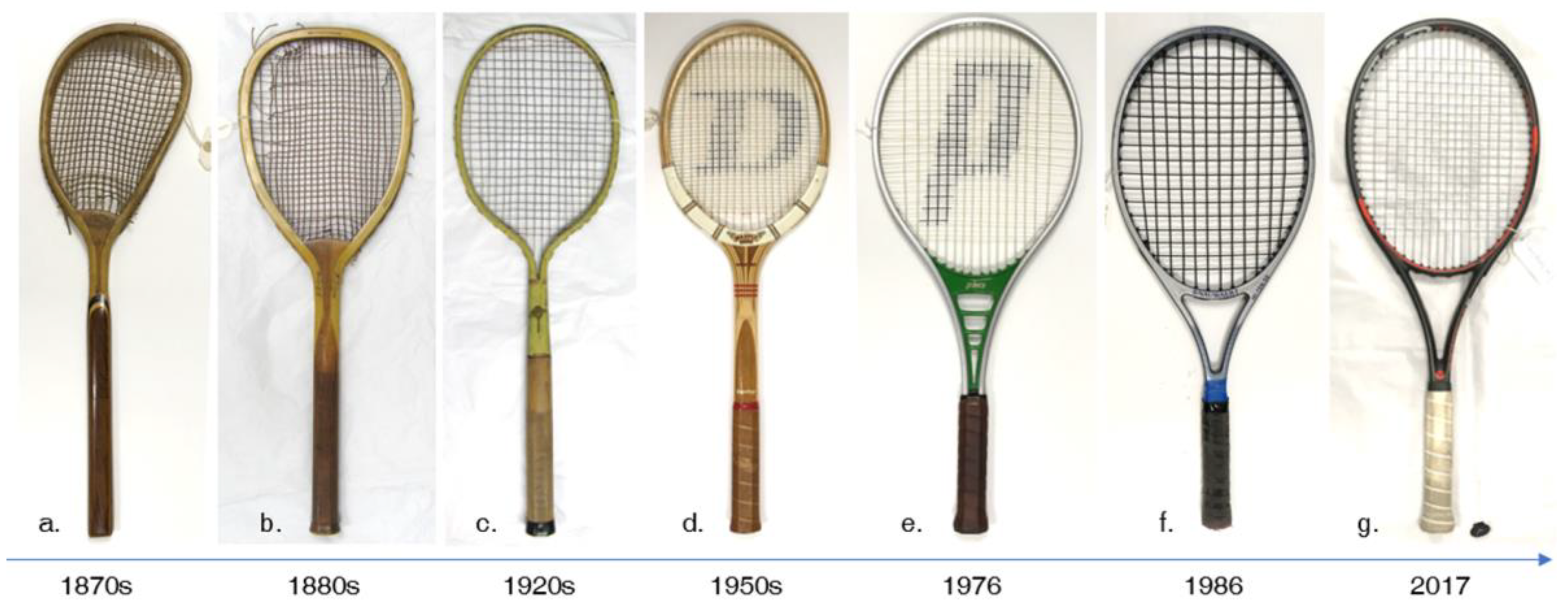
By comparing the photographs in Figure 9 (and those in Video S1 in the Supplementary Material) it is clear that the tennis racket has developed considerably since the 1870s. The wooden racket from the 1870s (Figure 9a) is characterised by the lopsided head typical of early designs. The racket from 1886 (Figure 9b) is symmetrical and highlights the move away from the lopsided design. The racket from 1922 (Figure 9c) has a wooden handle and steel head and throat that were intended to combat issues with wooden frames, such as breaking or warping. The racket was unsuccessful as steel offers limited damping (Figure 9), the original natural gut strings often broke where they contacted the frame (an issue solved later for metal rackets by the use of plastic ‘grommets’) and steel replacements damaged the ball. In contrast, the wooden Dunlop “Maxply” (Figure 9d) was made for over 50 years (1931–1983) with a small head and closed throat, as typical of designs from 1920 to 1970. The aluminium Prince “Classic” (Figure 9e) was the first oversize racket to be patented in 1976, although a patent was not gained in Germany, as a composite racket with a large head (Fortissimo, Bentley) was presented in Cologne in 1972 [2]. An earlier attempt at an oversize wooden racket was made by F. W. Donisthorpe in 1919 [2], and the museum had a racket from 1954 (Maxply, Dunlop) with a larger head than the Prince Classic, but it was badly warped (and not measured). The racket from 1986 (Figure 9f) highlights the modern design, characterised by a composite frame with a large head and an open throat. The racket from 2017 (Figure 9g) had a sensor (Tennis sensor, HEAD) for collecting data on the playing style of the user.
4. Discussion
Collected racket parameters were approximated by the main principal components (PCA1). Head sizes and natural frequencies of tennis rackets have changed most significantly during their development and correlate best with PCA1. We suggest that these main changes were likely to be facilitated by the increased stiffness of composite materials. Wood was the common material for tennis rackets until the 1960s, when composites were used as reinforcement on a wooden frame. By the 1970s, engineers were experimenting with steel, aluminium and fibre–polymer composites, as they are stronger than wood and allowed for rackets with larger heads. Oversized rackets made tennis easier to play, but metal frames had lower natural frequencies than their composite counterparts and offered limited damping, so that vibrations from ball contact away from the node (the ‘sweet spot’) lasted longer [40]. By the 1980s, composites had surpassed wood as the common racket material, providing engineers with more freedom over frame shape, stiffness, and mass distribution.
Many racket properties, such as the frame cross section shape (Figure 6b), mass (Figure 7a), Polar MOI (Figure 7c) and natural frequency (Figure 8a) were more varied in modern designs, giving the player greater choice to suit their style, experience and preference. The analysis presented here did not reveal a lasting brand that departed radically from established principles of tennis racket design. All brands tended to follow the same fundamentals with regards to head size, stiffness and material. Differences revealed in the analysis appear to have been due to the longevity of particular brands and the era of their presence within the marketplace. Observed differences were due to restrictions in racket material for a brand prevalent in the wooden era compared to modern tennis racket brands.
This study provides the first presentation of how string bed densities, damping and external cross section dimensions of tennis rackets have changed over time. While other racket parameters have been previously documented by Haake et al. [3], over three times more rackets were characterised here with a wider variety of measurements, analysis methods and reporting of materials. Findings agreed with Haake et al. [3] in terms of trends in properties since the 1870s, including overall length, grip and head length, head width, mass, CoM location, natural frequency and transverse MOI (reported as swingweight (Figure 1a) in [3]), but this study also shows how materials have driven the development of the tennis racket. Haake et al. [3] only includes rackets up to 2007; data presented here indicates that the rate of change for some properties, such as head size (Figure 5a) and mass (Figure 6a), may have slowed recently, since 2007. Haake et al. [3] showed scatter in their results for Polar MOI with no clear trend over time, while those reported here show little change until 1970 followed by a steady increase with the move to rackets with wider heads, as expected [29,38]. Haake et al. [3] estimated Polar MOI from measurements of transverse and lateral MOI (using a Babolat Racquet Diagnostic Centre) [3], and the assumption that a racket is planar, combined with uncertainty from two measures may have influenced their results [28]. Holding a racket by the handle can change modal frequencies and shapes and substantially increase damping [40,41,42], and future work could investigate the dynamic properties of rackets from different eras in more depth, if freely suspended, hand-held and with mass added at the handle to represent the hand.
While over 500 rackets were characterized, they do not represent all of the rackets that have ever been made. The reason each racket entered the museum collection is unknown, and could be due to factors such as availability, survival, design, and significance. The museum store is climate controlled, but the extent to which time, use or manufacturing inconsistencies affected racket properties, like natural frequency and damping, is unknown. The measurement techniques are time-consuming when applied to many rackets, and future work could look to make them quicker. Image processing could be used to obtain dimensions automatically from photographs [29], removing the need for manual measurements while improving estimates for properties like frame thickness and head area, and facilitating measurement of string spacing. Automated three-dimensional imaging devices [43] could also be used to scan rackets, to give a better representation of shape, including wall thickness in hollow metal and composite frames, which would allow for calculation of second moments of area. More efficient protocols could facilitate testing of more rackets, to produce a better picture of how they have developed over time. Repeat testing of different examples of the same racket could help to account for any manufacturing inconsistencies and deterioration.
The data collected here shows a distinct transition in racket design between the 1960s and 1990s, with almost all rackets now being made from fibre–polymer composites (Figure 3). It is possible that some parameters may have reached a new equilibrium today with, for instance, racket masses of around ~330 g, natural frequencies of ~143 Hz and transverse MOIs of ~0.047 kgm2. It might be beneficial to investigate how constituent materials and fiber orientations of composite rackets could influence performance, such as ball velocity and spin, and player perceptions and preferences [44,45], as well as injury risk [9,22,23]. While fibre–polymer composites have improved the tennis racket, their damping is limited, and manufacturing is currently labour intensive. Finite element models [13] could be produced for rackets from different eras, to further our understanding of how their development has influenced player performance, while also serving as design tools. Such finite element models could facilitate the application of new materials and manufacturing techniques to the tennis racket. Natural fibre composites, as used in some surfboards and fishing rods, could reduce the cost and environmental impact of making rackets [46], while auxetic composites [47] and those additively manufactured with continuous fibres [48,49,50] could bring more design freedom and support mass customisation for different players. Sensors incorporated within the frame could help brands develop a better understanding of how players use their rackets, and support mass customisation strategies. Simple measures, such as those described here, can be used to monitor changes in racket design.
5. Conclusions
Advances in materials have bought improvements to the tennis racket, such as a larger head to make it easier to play and a higher natural frequency to reduce energy loss to vibrations. The majority of changes have come since 1970, as fibre–polymer composites replaced wood as the common material for racket frames. Composites allow greater design freedom and the properties of modern rackets tend to be more diverse than their wooden predecessors. Composite rackets are produced in a manually intensive process, and offer limited damping. Further improvements to the tennis racket could come from automated production using materials with higher damping.
Supplementary Materials
The following are available online at https://0-www-mdpi-com.brum.beds.ac.uk/2076-3417/9/20/4352/s1, Table S1: Measured and recorded properties for the 525 rackets used in this research. Video S1: The historical development of tennis rackets.
Author Contributions
Conceptualization, L.T., R.G., M.S., S.C., J.S., S.H. and T.A.; Data curation, L.T.; Formal analysis, L.T. and R.G.; Funding acquisition, L.T., R.G., M.S., S.C., J.S., S.H. and T.A.; Methodology, L.T., R.G., M.S. and T.A.; Supervision, R.G., M.S. and T.A.; Writing—original draft, L.T., R.G. and T.A.; Writing—review & editing, L.T., R.G., S.C., S.H. and T.A.
Funding
University of Rome “La Sapienza” and Two International Sports Engineering Association (ISEA) student engagement awards.
Acknowledgments
The authors wish to thank Matthew Glaze and the Wimbledon Lawn Tennis Museum Office staff for their kind and useful support and for providing access to the museum store. The authors would like to thank Stefan Mohr and the other staff at HEAD Sports for providing access to their racket collection. The authors wish to acknowledge the students William Dawber and Frank Hopkins, who each benefited from an ISEA student engagement award, for the assistance in measuring the rackets of the Wimbledon Lawn Tennis Museum. The authors wish to acknowledge the University of Rome “La Sapienza” for providing funding for this work.
Conflicts of Interest
The authors declare no conflict of interest.
References
- Wingfield, W. Sphairistikè or Lawn Tennis; Artist’s and Photographers’ Press Ltd.: London, UK, 1874. [Google Scholar]
- Kuebler, S. Book of Tennis Rackets: From the Beginning in the 16th Century until about 1990; Kuebler: Stuttgart, Germany, 2000; pp. 1–635. [Google Scholar]
- Haake, S.J.; Allen, T.B.; Choppin, S.B.; Goodwill, S.R. The evolution of the tennis racket and its effect on serve speed. In Tennis Science and Technology; Miller, S., Capel-Davies, J., Eds.; International Tennis Federation: London, UK, 2007; Volume 3, pp. 257–271. [Google Scholar]
- Lammer, H.; Kotze, J. Materials and tennis rackets. In Materials in Sports Equipment; Jenkins, M., Ed.; Woodhead Publishing: Cambridge, UK, 2003; Volume 1, pp. 222–248. [Google Scholar]
- Wimbledon. Available online: www.wimbledon.com/en_GB/aboutwimbledon/prize_money_and_finance.html (accessed on 4 August 2019).
- Head, H. Tennis Racket. U.S. Patent 3,999,756, 28 December 1976. [Google Scholar]
- International Tennis Federation. ITF Rules of Tennis 2019; ITF: London, UK, 2019; pp. 1–44.
- Cross, R. Impact of sports balls with striking implements. Sports Eng. 2014, 17, 3–22. [Google Scholar] [CrossRef]
- Miller, S. Modern tennis rackets, balls, and surfaces. Br. J. Sports Med. 2006, 40, 401–405. [Google Scholar] [CrossRef] [PubMed]
- Brody, H. Models of tennis racket impacts. J. Appl. Biomech. 1987, 3, 293–296. [Google Scholar] [CrossRef]
- Kotze, J.; Mitchell, S.R.; Rothberg, S.J. The role of the racket in high speed tennis serves. Sports Eng. 2000, 3, 67–84. [Google Scholar] [CrossRef]
- Elliott, B.C. Tennis strokes and equipment. In Biomechanics of Sport; Vaughan, C.L., Ed.; CRC Press: Boca Raton, FL, USA, 1989; pp. 263–288. [Google Scholar]
- Allen, T.; Haake, S.; Goodwill, S. Comparison of a finite element model of a tennis racket to experimental data. Sports Eng. 2009, 12, 87–98. [Google Scholar] [CrossRef]
- Allen, T.; Haake, S.; Goodwill, S. Effect of friction on tennis ball impacts. Proc. Inst. Mech. Eng. Part P J. Sports Eng. Technol. 2010, 224, 229–236. [Google Scholar] [CrossRef]
- Allen, T.B.; Haake, S.J.; Goodwill, S.R. Effect of tennis racket parameters on a simulated groundstroke. J. Sports Sci. 2011, 29, 311–325. [Google Scholar] [CrossRef]
- Knudson, D.; Allen, T.B.; Choppin, S.B. Interaction of tennis racket design and biomechanical factors. In Routledge Handbook of Ergonomics in Sport and Exercise; Hong, Y., Ed.; Routledge: New York, NY, USA, 2013; pp. 423–439. [Google Scholar]
- Allen, T.; Choppin, S.; Knudson, D. A review of tennis racket performance parameters. Sports Eng. 2016, 19, 1–11. [Google Scholar] [CrossRef]
- Mitchell, S.R.; Jones, R.; King, M. Head speed vs. racket inertia in the tennis serve. Sport Eng. 2000, 3, 99–110. [Google Scholar] [CrossRef]
- Schorah, D.; Choppin, S.; James, D. Effects of moment of inertia on restricted motion swing speed. Sport Biomech. 2015, 14, 157–167. [Google Scholar] [CrossRef]
- Whiteside, D.; Elliott, B.; Lay, B.; Reid, M. The effect of racquet swing weight on serve kinematics in elite adolescent female tennis players. J. Sci. Med. Sport 2013, 17, 124–128. [Google Scholar] [CrossRef] [PubMed]
- Cross, R.; Bower, R. Effects of swing-weight on swing speed and racket power. J. Sports Sci. 2006, 24, 23–30. [Google Scholar] [CrossRef]
- Allen, T.; Dixon, S.; Dunn, M.; Knudson, D. Tennis equipment and technique interactions on risk of overuse injuries. In Tennis Medicine; Springer: Cham, Switzerland, 2018; pp. 61–79. [Google Scholar]
- Hennig, E.M. Influence of racket properties on injuries and performance in tennis. Exerc. Sport Sci. Rev. 2007, 35, 62–66. [Google Scholar] [CrossRef] [PubMed]
- Schnohr, P.; O’Keefe, J.H.; Holtermann, A.; Lavie, C.J.; Lange, P.; Jensen, G.B.; Marott, J.L. Various leisure-time physical activities associated with widely divergent life expectancies: The Copenhagen City Heart Study. Mayo Clin. Proc. 2018, 93, 1775–1785. [Google Scholar] [CrossRef]
- Christie, D. Tennis rackets and the parallel axis theorem. Phys. Teach. 2014, 52, 208–209. [Google Scholar] [CrossRef]
- Eng, J.; Lietman, T. Measuring the velocity of a tennis serve. Phys. Teach. 1994, 32, 168–172. [Google Scholar] [CrossRef]
- Allen, T.; Goff, J.E. Resources for sports engineering. Sports Eng. 2017, 21, 245–253. [Google Scholar] [CrossRef]
- Allen, T.; Grant, R.; Sullivan, M.; Taraborrelli, L.; Choppin, S.J.S.; Haake, S.J. Recommendations for measuring tennis racket parameters. Proceedings 2018, 2, 263. [Google Scholar] [CrossRef]
- Taraborrelli, L.; Grant, R.; Sullivan, M.; Choppin, S.; Spurr, J.; Haake, S.J.; Allen, T. Recommendations for estimating the moments of inertia of a tennis racket. Sports Eng. 2019, 22, 1–9. [Google Scholar] [CrossRef]
- Tennis Warehouse. Available online: https://tt.tennis-warehouse.com/index.php (accessed on 4 August 2019).
- Tennis Discutiamo. Available online: http://tennis.discutiamo.com/marche.php (accessed on 4 August 2019).
- De Silva, C.W. Vibration: Fundamentals and Practice, 2nd ed.; Taylor & Francis: Boca Raton, FL, USA, 2006; pp. 1–1064. [Google Scholar]
- Cross, R. Impact of a ball with a bat or racket. Am. J. Phys. 1999, 67, 692–702. [Google Scholar] [CrossRef] [Green Version]
- Cross, R. Factors affecting the vibration of tennis racquets. Sports Eng. 2015, 18, 135–147. [Google Scholar] [CrossRef]
- Hotelling, H. Analysis of a complex of statistical variables into principal components. J. Educ. Psychol. 1933, 24, 498–520. [Google Scholar] [CrossRef]
- Cohen, J. Statistical Power Analysis for the Behavioral Sciences, 2nd ed.; Erlbaum: Hillsdale, NJ, USA, 1988. [Google Scholar]
- Kuebler, S. Racket having thickened shaft portion. U.S. Patent 4,664,380, 12 May 1987. [Google Scholar]
- Brody, H. The moment of inertia of a tennis racket. Phys. Teach. 1985, 23, 213–216. [Google Scholar] [CrossRef]
- Ashby, M.F. Materials Selection in Mechanical Design, 5th ed.; Butterworth-Heinemann: Oxford, UK, 2016; pp. 1–639. [Google Scholar]
- Brody, H. Vibration damping of tennis rackets. J. Appl. Biomech. 1989, 5, 451–456. [Google Scholar] [CrossRef]
- Chadefaux, D.; Rao, G.; Le Carrou, J.L.; Berton, E.; Vigouroux, L. The effects of player grip on the dynamic behaviour of a tennis racket. J. Sports Sci. 2017, 35, 1155–1164. [Google Scholar] [CrossRef] [PubMed]
- Banwell, G.H.; Roberts, J.R.; Halkon, B.J.; Rothberg, S.J.; Mohr, S. Understanding the dynamic behaviour of a tennis racket under play conditions. Exp. Mech. 2014, 54, 527–537. [Google Scholar] [CrossRef]
- Emerson, N.J.; Offiah, A.C.; Reilly, G.C.; Carré, M.J. Patient-Specific Finite Element Modelling and Validation of Porcine Femora in Torsion. Strain 2013, 49, 212–220. [Google Scholar] [CrossRef]
- Roberts, J.R.; Jones, R.; Rothberg, S.J.; Mansfield, N.J.; Meyer, C. Influence of sound and vibration from sports impacts on players’ perceptions of equipment quality. Proc. Inst. Mech. Eng. Part L J. Mater. Des. Appl. 2006, 220, 215–227. [Google Scholar] [CrossRef]
- Kim, H.E.; Pennings, J.M. Innovation and strategic renewal in mature markets: A study of the tennis racket industry. Organ. Sci. 2009, 20, 368–383. [Google Scholar] [CrossRef]
- Pickering, K.L.; Efendy, M.A.; Le, T.M. A review of recent developments in natural fibre composites and their mechanical performance. Compos. Part A Appl. Sci. Manuf. 2016, 83, 98–112. [Google Scholar] [CrossRef] [Green Version]
- Duncan, O.; Shepherd, T.; Moroney, C.; Foster, L.; Venkatraman, P.; Winwood, K.; Allen, T.; Alderson, A. Review of auxetic materials for sports applications: Expanding options in comfort and protection. Appl. Sci. 2018, 8, 941. [Google Scholar] [CrossRef]
- Parandoush, P.; Lin, D. A review on additive manufacturing of polymer-fiber composites. Compos. Struct. 2017, 182, 36–53. [Google Scholar] [CrossRef]
- Goh, G.D.; Yap, Y.L.; Agarwala, S.; Yeong, W.Y. Recent progress in additive manufacturing of fibre reinforced polymer composite. Adv. Mat. Tech. 2019, 4, 1800271. [Google Scholar]
- Le Duigou, A.; Barbé, A.; Guillou, E.; Castro, M. 3D printing of continuous flax fibre reinforced biocomposites for structural applications. Mater. Des. 2019, 180, 107884. [Google Scholar] [CrossRef]
Figure 1.
(a) Diagram showing the measured geometric and mass properties and moments of inertia (MOI) of a tennis racket; (b) Diagrams showing the racket head measurements and the definition of head area (ha); (c) photographs showing the definitions of frame thickness and depth; (d) a wooden racket with a lopsided frame, flat top head and a convex wedge in the throat section, showing an Egyptian stringing pattern; (e) an aluminium racket with a circular head and a twin shaft throat with an extra yoke and an insert made of a different material (plastic); (f) a throat section with no yoke, typical of Dayton steel rackets; and (g) an example of an ornate, “fish-tail” handle of an old wooden racket.

Figure 2.
Example of fft of the vibration signal of a tennis racket (~134 Hz). Large yellow dots are the original fft points and the small blue dots represent the spline fitting used for damping estimation.
Figure 2.
Example of fft of the vibration signal of a tennis racket (~134 Hz). Large yellow dots are the original fft points and the small blue dots represent the spline fitting used for damping estimation.

Figure 3.
Bar charts showing: (a) The percentage of rackets of each material per decade (the values above the columns represent the number of rackets from each decade); and (b) the mean length of the grip, throat region and head (ext.) and the CoM location for the rackets per decade.
Figure 3.
Bar charts showing: (a) The percentage of rackets of each material per decade (the values above the columns represent the number of rackets from each decade); and (b) the mean length of the grip, throat region and head (ext.) and the CoM location for the rackets per decade.

Figure 4.
Bar charts showing the percentage of rackets with certain distinguishing features per decade; (a) head; (b) throat; (c) handle and (d) stringing pattern. Other features correspond to cases were there were less than five examples.
Figure 4.
Bar charts showing the percentage of rackets with certain distinguishing features per decade; (a) head; (b) throat; (c) handle and (d) stringing pattern. Other features correspond to cases were there were less than five examples.

Figure 5.
Change in geometry of tennis rackets from 1870s; (a) estimated head area; (b) string bed density and (c) the ratio between frame depth and thickness.
Figure 5.
Change in geometry of tennis rackets from 1870s; (a) estimated head area; (b) string bed density and (c) the ratio between frame depth and thickness.

Figure 6.
Change in inertial properties of tennis rackets from 1870s: (a) Mass; (b) estimated transverse MOI; and (c) polar MOI.
Figure 6.
Change in inertial properties of tennis rackets from 1870s: (a) Mass; (b) estimated transverse MOI; and (c) polar MOI.

Figure 7.
Dynamic properties of tennis rackets from the 1870s: (a) Natural frequencies; (b) damping coefficients; (c) natural frequencies vs.damping and (d) vibration signals in time domain (legend indicates natural frequency and damping coefficient).
Figure 7.
Dynamic properties of tennis rackets from the 1870s: (a) Natural frequencies; (b) damping coefficients; (c) natural frequencies vs.damping and (d) vibration signals in time domain (legend indicates natural frequency and damping coefficient).

Figure 8.
Results of PCA: (a) PCA1 vs. year, showing materials; (b) PCA 1 vs. head area, showing materials; (c) PCA2 vs. year, showing brands; (d) PCA 2 vs. CoM location, showing brands.
Figure 8.
Results of PCA: (a) PCA1 vs. year, showing materials; (b) PCA 1 vs. head area, showing materials; (c) PCA2 vs. year, showing brands; (d) PCA 2 vs. CoM location, showing brands.

Figure 9.
Seven tennis rackets showing developments over time: (a) Early racket by F. H. Ayres (1870s); (b) wooden racket by F. H. Ayres (1886); (c) steel racket by Dayton Steel Racket Corporation (1922); (d) Dunlop “Maxply” (1955); (e) Prince “Classic” (1976); (f) Snauwaert Hi-Ten 50 (1986); (g) Head Graphene XT Prestige with the sensor (2017).


Table 1.
Properties documented and measured for each racket.
| Property Type | Details | Method |
|---|---|---|
| Brand | Brand name, racket name and model, date, material/s | Book [2], museum catalogue and websites [30,31], visual inspection |
| Geometric | Length 1, head length/width (ext. and int.) 1, grip length 1, max. and min. frame depth 2 | Measuring tape, callipers |
| Inertial | Mass 3, centre of mass (CoM) from butt, Transverse and Polar MOI 4 | Scales and support |
| Dynamic | Frequency and damping ratio of the first bending mode | Modal analysis with accelerometer |
| String | No. main/cross strings | - |
Resolution: 1 1 mm using measuring tape; 2 0.1 mm using callipers; and 3 0.1 g using a scale (Smart Weigh SWS1KG Elite Series); and 4 estimated using models [29]
© 2019 by the authors. Licensee MDPI, Basel, Switzerland. This article is an open access article distributed under the terms and conditions of the Creative Commons Attribution (CC BY) license (http://creativecommons.org/licenses/by/4.0/).
Share and Cite
MDPI and ACS Style
Taraborrelli, L.; Grant, R.; Sullivan, M.; Choppin, S.; Spurr, J.; Haake, S.; Allen, T. Materials Have Driven the Historical Development of the Tennis Racket. Appl. Sci. 2019, 9, 4352. https://0-doi-org.brum.beds.ac.uk/10.3390/app9204352
AMA Style
Taraborrelli L, Grant R, Sullivan M, Choppin S, Spurr J, Haake S, Allen T. Materials Have Driven the Historical Development of the Tennis Racket. Applied Sciences. 2019; 9(20):4352. https://0-doi-org.brum.beds.ac.uk/10.3390/app9204352
Chicago/Turabian StyleTaraborrelli, Luca, Robyn Grant, Matthew Sullivan, Simon Choppin, James Spurr, Steve Haake, and Tom Allen. 2019. "Materials Have Driven the Historical Development of the Tennis Racket" Applied Sciences 9, no. 20: 4352. https://0-doi-org.brum.beds.ac.uk/10.3390/app9204352
Note that from the first issue of 2016, this journal uses article numbers instead of page numbers. See further details here.