A Review of Hydrogen Direct Injection for Internal Combustion Engines: Towards Carbon-Free Combustion

 , ,
, ,  , , , and
Abstract
:Contents
| 1 | Introduction | 2 | ||
| 1.1 | Hydrogen Application and Production | 2 | ||
| 1.2 | The Potential for Hydrogen | 3 | ||
| 1.3 | Recent Developments of Hydrogen Applications in the Transportation Sector | 4 | ||
| 1.4 | Scope | 4 | ||
| 2 | Hydrogen Properties and Their Implications on Use in Internal Combustion Engine | 5 | ||
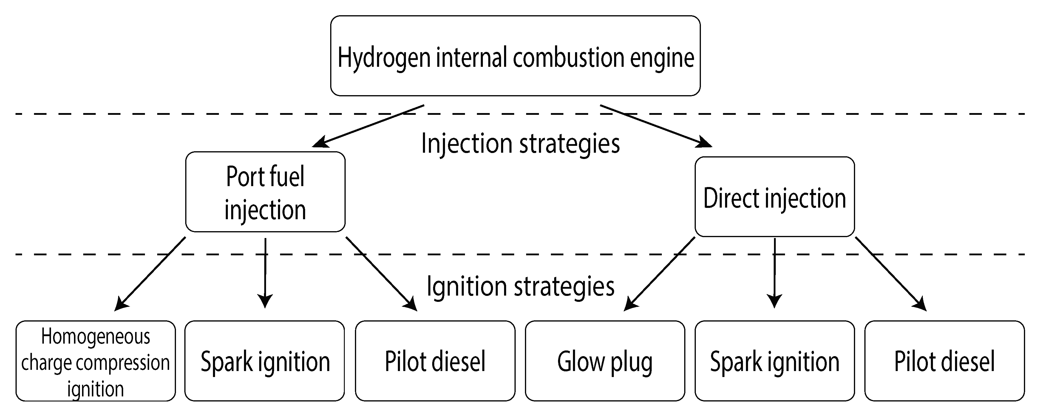
| 3 | Hydrogen Engine Combustion Modes | 6 | ||
| 4 | Hydrogen Port Fuel Injection | 7 | ||
| 4.1 | Homogeneous Charge Compression Ignition | 7 | ||
| 4.2 | Spark-Ignited Port Fuel Injection | 7 | ||
| 4.3 | Pilot-Fuel-Ignited Engine with Port Hydrogen Injection | 8 | ||
| 5 | Hydrogen Only Combustion with Direct Injection | 9 | ||
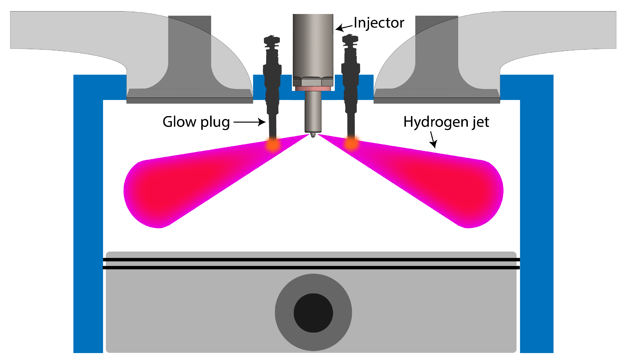
| 5.1 | Glow-Plug-Assisted Ignition | 9 | ||
| 5.2 | Spark-Assisted Ignition | 10 | ||
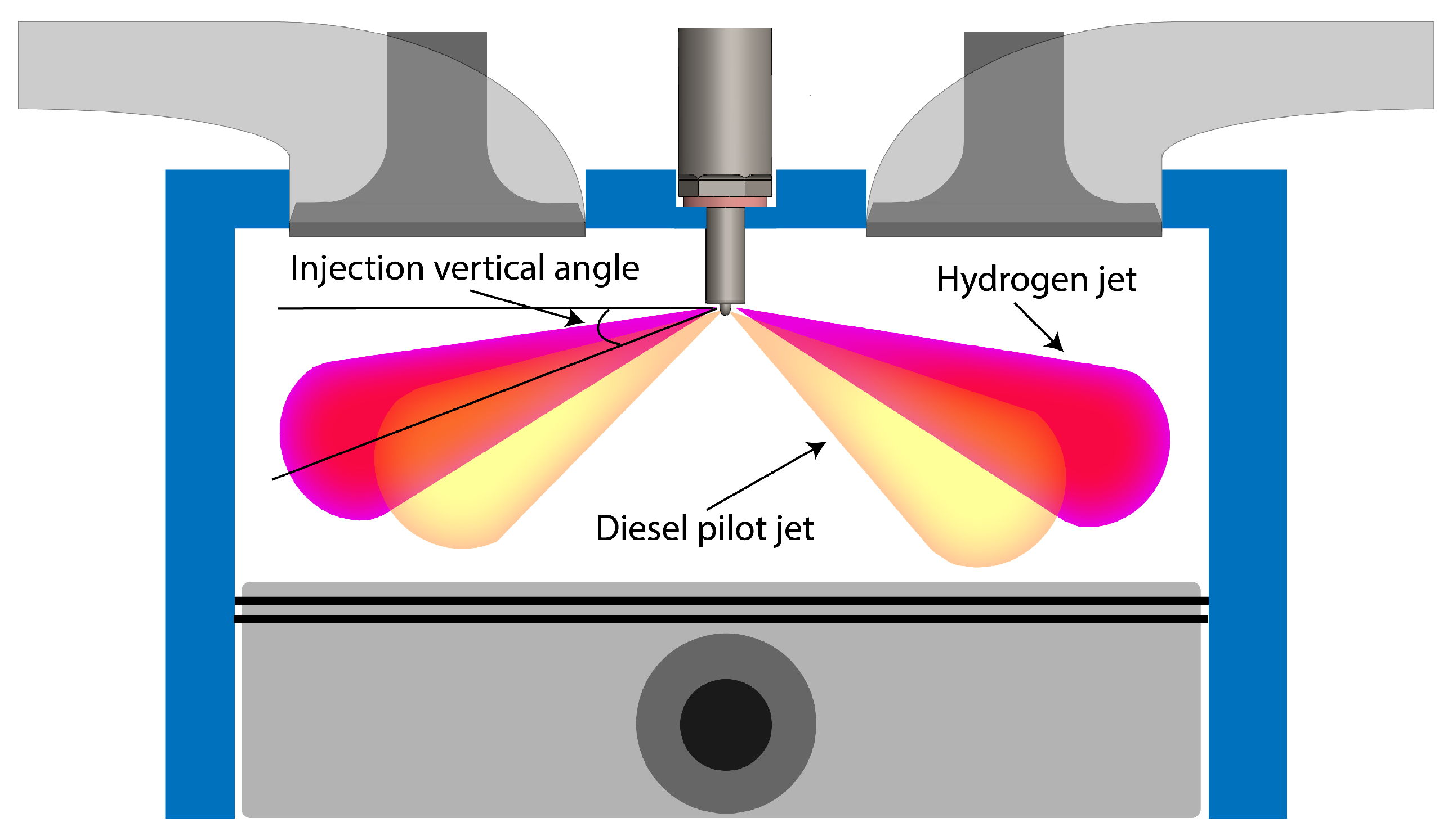
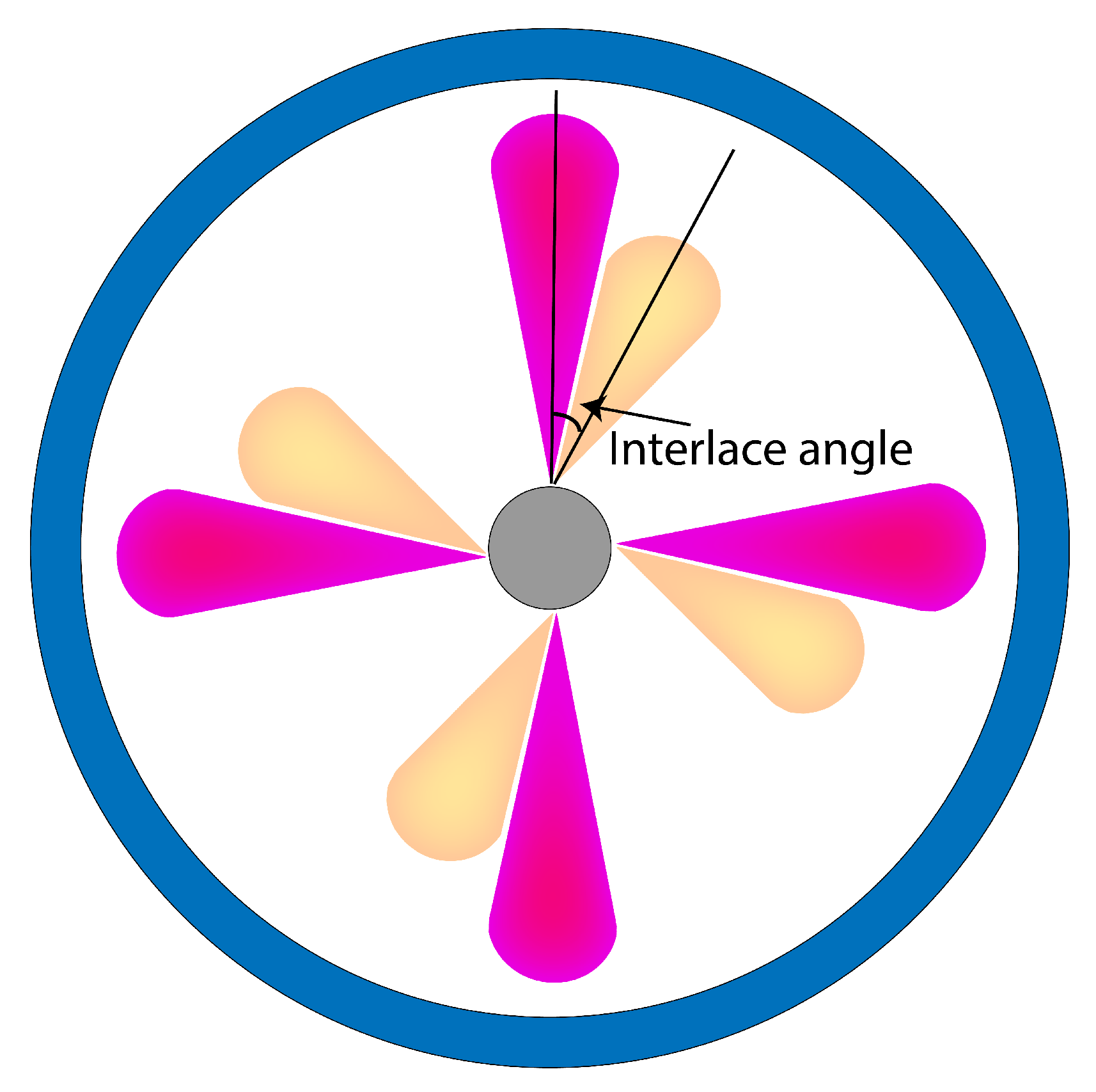
| 6 | Dual-Fuel High Pressure Direct Injection Compression-Ignition Engine | 11 | ||
| 7 | Non-Premixed Hydrogen Diffusion Combustion | 16 | ||
| 8 | Fuel System for High Pressure Hydrogen Injection | 17 | ||
| 8.1 | Injector Design Considerations | 19 | ||
| 8.1.1 Injection Rate | 19 | |||
| 8.1.2 Axial Jet Penetration | 21 | |||
| 8.2 | Fuel Delivery Strategies | 23 | ||
| 9 | Conclusions | 23 | ||
| References | 25 | |||
1. Introduction
1.1. Hydrogen Application and Production
1.2. The Potential for Hydrogen
1.3. Recent Developments of Hydrogen Applications in the Transportation Sector
1.4. Scope
2. Hydrogen Properties and Their Implications on Use in Internal Combustion Engine
3. Hydrogen Engine Combustion Modes
4. Hydrogen Port Fuel Injection
4.1. Homogeneous Charge Compression Ignition
4.2. Spark-Ignited Port Fuel Injection
4.3. Pilot-Fuel-Ignited Engine with Port Hydrogen Injection
5. Hydrogen Only Combustion with Direct Injection
5.1. Glow-Plug-Assisted Ignition
5.2. Spark-Assisted Ignition
6. Dual-Fuel High Pressure Direct Injection Compression-Ignition Engine
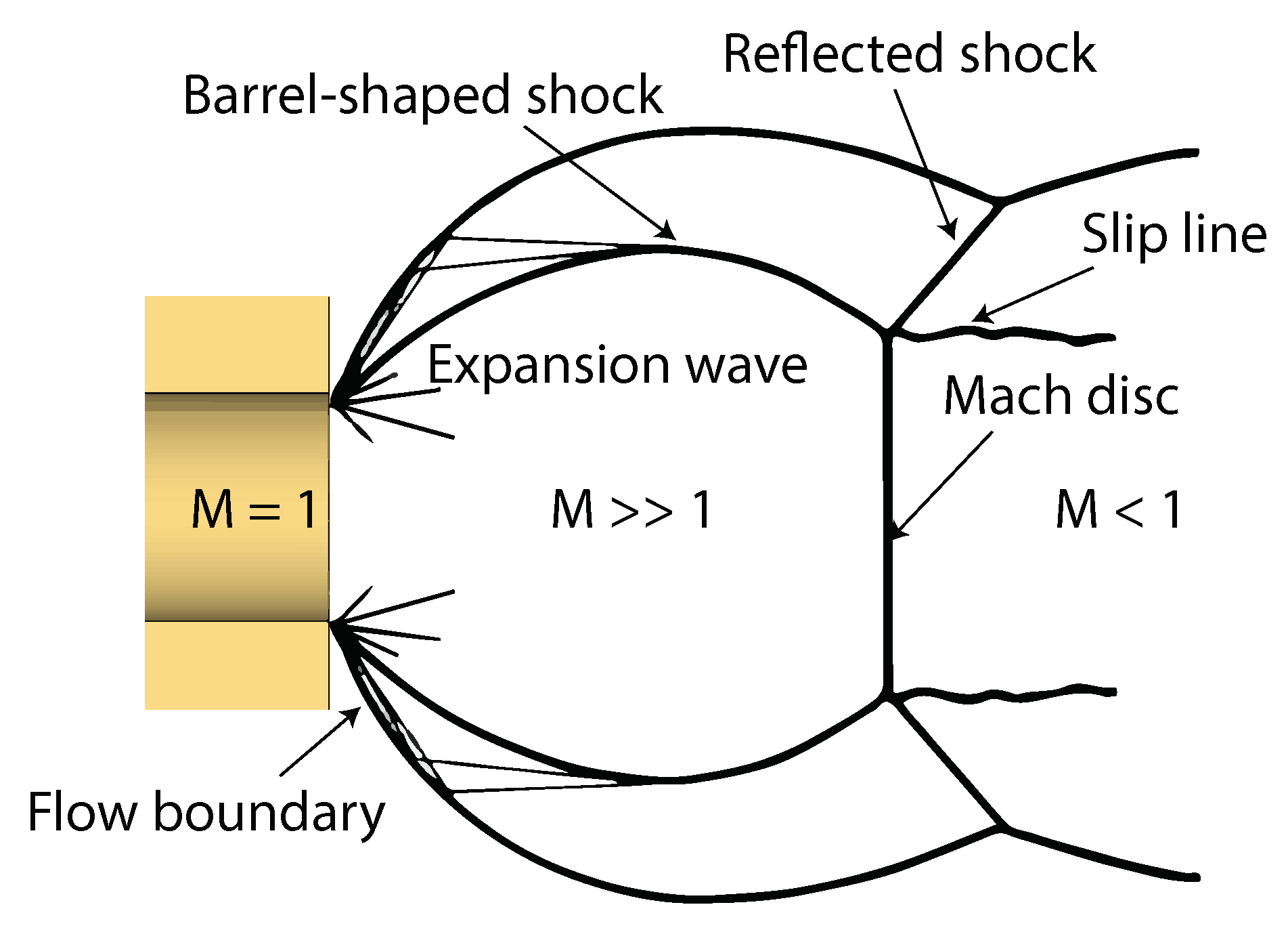
7. Non-Premixed Hydrogen Diffusion Combustion
Gas Jet Model
8. Fuel System for High Pressure Hydrogen Injection
- (1)
- Electrohydraulic-actuated (NTSEL): This type of injector requires high-pressure hydraulic fluid (usually diesel fuel) for actuation. The injection pressure is limited to 200 bar. During the injection actuation, the electronically-triggered solenoid acts on the pilot-needle to relieve diesel pressure at the upper part of the injector, reducing hydraulic force that pushes the needle into its seat. Therefore, the high pressure hydrogen can lift the needle and the injection begins. In this design, the diesel pressure needs to be high enough to ensure needle sealing in closed position. It also provides lubrication to some of the injector moving parts. However, the long opening transient duration due to the inertia of hydraulic actuation system might be undesirable in some applications.
- (2)
- Solenoid-driven (Westport): The first generation Westport hydrogen DI technology is entirely driven by a solenoid. The direct solenoid actuation imposes an injection pressure limit, which is the lowest among the listed injectors at 150 bar. In addition, a serious durability issue was reported and attributed to the lack of needle motion control required to minimize the needle impact into the seat. Hoerbiger Valve TEC GmbH has also developed a similar solenoid-driven hydrogen DI injector but with a maximum injection pressure of 100 bar [72].
- (3)
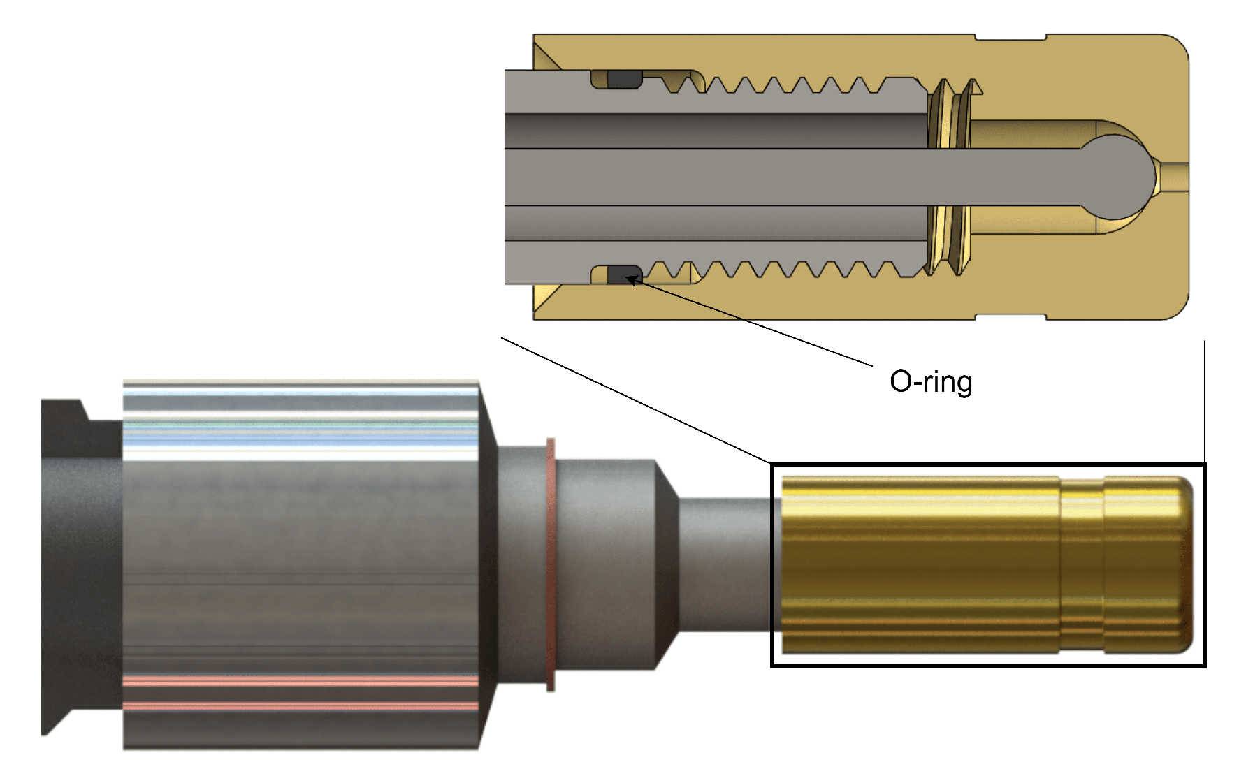
- Piezo-driven (Westport): This second generation injector with maximum injection pressure of 250 bar is directly driven by a piezoelectric crystal, using analog voltage to proportionally control the needle displacement, enabling a very fast response time. It has a short opening transient duration of 0.5 ms, similar to their solenoid-driven design but only with 35% of that of the NTSEL’s injector. Additionally, the injector lifetime is improved by the flexible control of the needle velocity, which can be decelerated at closing to reduce impact. Multiple injections can also be performed.
8.1. Injector Design Considerations
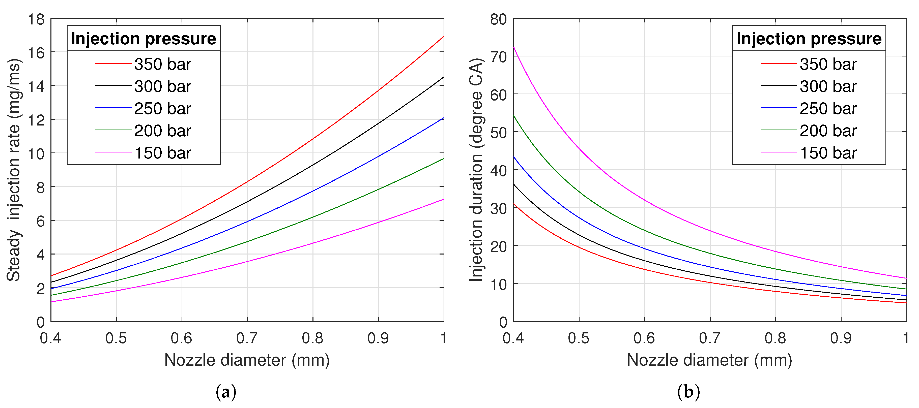
8.1.1. Injection Rate
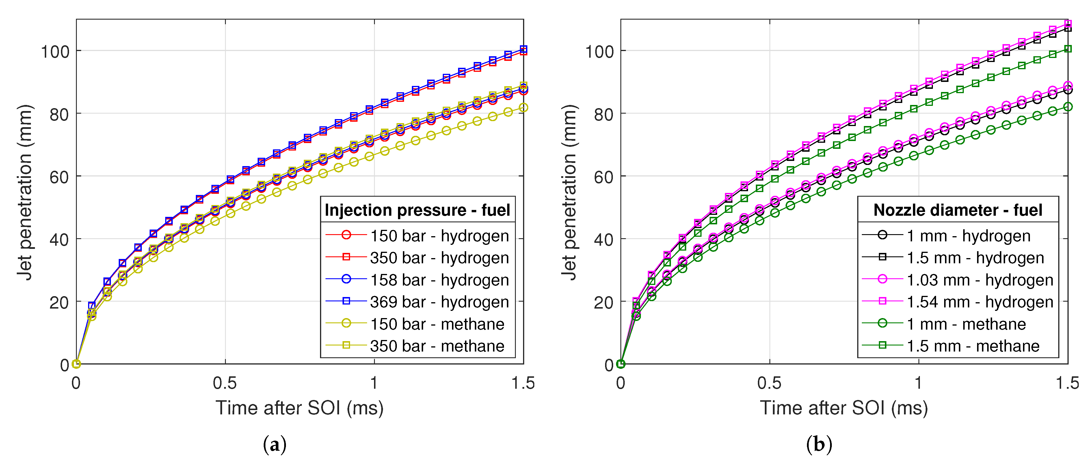
8.1.2. Axial Jet Penetration
8.2. Fuel Delivery Strategies
9. Conclusions
- Metal engine testing is required to prove the effectiveness of this combustion concept in terms of emissions and performance, and to investigate the effect of different operating parameters, for instance injector configuration and operation strategy.
- Fundamental optical and laser-based investigation as well as numerical simulations are needed to understand the governing mechanisms to facilitate engine performance optimization.
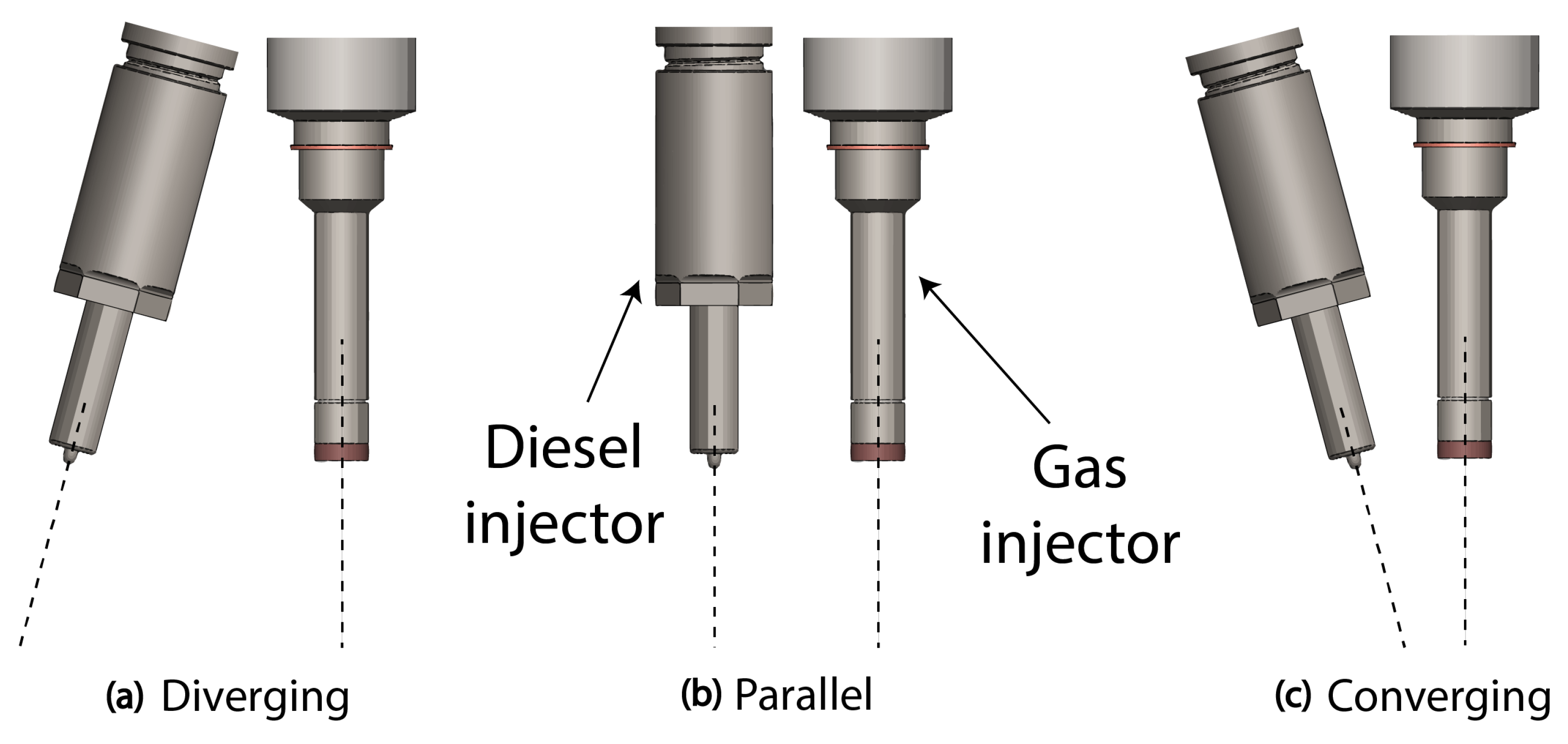
- For research purposes, this combustion mode can be studied by using single-fuel injectors—prototype injectors for hydrogen while using commercial diesel injectors to deliver pilot fuel. An integrated dual-fuel injector for hydrogen and pilot fuel may be needed as a long term solution.
- Further technological advancement towards a complete, compact, cost-efficient and robust on-board fuel delivery system is required for commercialization.
Author Contributions
Funding
Acknowledgments
Conflicts of Interest
Abbreviations
| ARENA | Australian Renewable & Energy Agency |
| BMEP | Brake mean effective pressure |
| BTDC | Before top dead center |
| BTE | Brake thermal efficiency |
| CA | Crank angle |
| CI | Compression ignition/compression ignited |
| CNG | Compressed natural gas |
| DI | Direct injection |
| EGR | Exhaust gas recirculation |
| FC | Fuel cell |
| GDI | Gasoline direct injection |
| HCCI | Homogeneous charge compression ignition |
| H2DDI | Hydrogen-diesel direct injection |
| HPDI | High pressure direct injection |
| ICE | Internal combustion engine |
| IMEP | Indicated mean effective pressure |
| ITE | Indicated thermal efficiency |
| MON | Motor Octane Number |
| NTSEL | National Traffic Safety & Environment Laboratory |
| PFI | Port fuel injection |
| RCEM | Rapid compression and expansion machine |
| RON | Research Octane Number |
| SI | Spark ignition/spark ignited |
| SOI | Start of injection |
| Nomenclature | |
| A | Area |
| d | Diameter |
| D | Jet width |
| Maximum mass flow rate | |
| P | Pressure |
| R | Specific gas constant |
| s | Ratio of jet tip penetration to jet width |
| T | Temperature |
| t | Time after SOI |
| u | Velocity |
| Z | Jet tip penetration |
| Density | |
| Equivalence ratio | |
| Specific heat ratio | |
| Subscripts | |
| a | Ambient condition |
| o | Infinite fuel supply reservoir |
| Effective | |
| t | Time after SOI |
| Superscript | |
| Sonic condition | |
References
- Dong, X.; Wang, B.; Yip, H.L.; Chan, Q.N. CO2 emission of electric and gasoline vehicles under various road conditions for China, Japan, Europe and world average—Prediction through year 2040. Appl. Sci. 2019, 9, 2295. [Google Scholar] [CrossRef]
- Berry, G.D.; Pasternak, A.D.; Rambach, G.D.; Smith, J.R.; Schock, R.N. Hydrogen as a future transportation fuel. Energy 1996, 21, 289–303. [Google Scholar] [CrossRef]
- Sharma, S.; Ghoshal, S.K. Hydrogen the future transportation fuel: From production to applications. Renew. Sustain. Energy Rev. 2015, 43, 1151–1158. [Google Scholar] [CrossRef]
- Das, L.M. Hydrogen engines: A view of the past and a look into the future. Int. J. Hydrogen Energy 1990, 15, 425–443. [Google Scholar] [CrossRef]
- Winkler-Goldstein, R.; Rastetter, A. Power to gas: The final breakthrough for the hydrogen economy? Green 2013, 3, 69–78. [Google Scholar] [CrossRef]
- Abdalla, A.M.; Hossaina, S.; Nisfindy, O.B.; Azadd, A.T.; Dawoodb, M.; Azada, A.K. Hydrogen production, storage, transportation and key challenges with applications: A review. Energy Convers. Manag. 2018, 165, 602–627. [Google Scholar] [CrossRef]
- Hydrogen Scaling Up: A Sustainable Pathway for the Global Energy Transition; Hydrogen Council: Belgium, 2017.
- Oil Market Report; International Energy Agency: Paris, France, 2019.
- The Observatory of Economic Complexity. Hydrogen Trade. Available online: https://atlas.media.mit.edu/en/profile/hs92/2804/ (accessed on 18 June 2019).
- Bruce, S.; Temminghoff, M.; Hayward, J.; Schmidt, E.; Munnings, C.; Palfreyman, D.; Hartley, P. National Hydrogen Roadmap: Pathways to an Economically Sustainable Industry; The Commonwealth Scientific and Industrial Research Organization: Canberra, Australia, 2018. [Google Scholar]
- Palmer, G. Australia’s Hydrogen Future; Energy Transition Hub: Melbourne, Australia, 2018. [Google Scholar]
- Basic Hydrogen Strategy; The Ministry of Economy, Trade and Industry: Tokyo, Japan, 2017.
- Wegener, J. Developments in Green Hydrogen Production and Use in Germany; National Organization Hydrogen and Fuel Cell Technology: Berlin, Germany, 2019. [Google Scholar]
- Banerjee, S.; Musa, M.N.; Jaafar, A.B. Economic assessment and prospect of hydrogen generated by OTEC as future fuel. Int. J. Hydrogen Energy 2017, 42, 26–37. [Google Scholar] [CrossRef]
- Maggio, G.; Nicita, A.; Squadrito, G. How the hydrogen production from RES could change energy and fuel markets: A review of recent literature. Int. J. Hydrogen Energy 2019, 44, 11371–11384. [Google Scholar] [CrossRef]
- Cornell, A. Hydrogen production by electrolysis. In Proceedings of the 1st International Conference on Electrolysis, Copenhagen, Denmark, 13–15 June 2017. [Google Scholar]
- Hydrogen Enabling a Zero Emission Europe: Technology Roadmaps Full Pack; Hydrogen Europe: Brussels, Belgium, 2018.
- Hydrogen from Renewable Power: Technology Outlook for the Energy Transition; International Renewable Energy Agency: Abu Dhabi, UAE, 2018.
- Opportunities for Australia from Hydrogen Exports; ACIL Allen Consulting: Sydney, Australia, 2018.
- The Green Hydrogen Economy in the Northern Netherlands; Noordelijke Innovation Board: Groningen, The Netherlands, 2017.
- International Energy Agency. Hydrogen: A Key Part of a Clean and Secure Energy Future. Available online: https://www.iea.org/topics/hydrogen/demand/ (accessed on 19 October 2019).
- Helmolt, R.V.; Eberle, U. Fuel cell vehicles: Status 2007. J. Power Sources 2007, 165, 833–843. [Google Scholar] [CrossRef]
- Hänggi, S.; Elbert, P.; Bütler, T.; Cabalzar, U.; Teske, S.; Bach, C.; Onder, C. A review of synthetic fuels for passenger vehicles. Energy Rep. 2019, 5, 555–569. [Google Scholar] [CrossRef]
- Manoharan, Y.; Hosseini, S.E.; Butler, B.; Alzhahrani, H.; Senior, B.T.F.; Ashuri, T.; Krohn, J. Hydrogen fuel cell vehicles; Current status and future prospect. Appl. Sci. 2019, 9, 2296. [Google Scholar] [CrossRef]
- Toyota and Kenworth unveil fuel cell heavy truck at Port of LA. Fuel Cells Bull. 2019, 2019, 3–4.
- Verhelst, S. Recent progress in the use of hydrogen as a fuel for internal combustion engines. Int. J. Hydrogen Energy 2014, 39, 1071–1085. [Google Scholar] [CrossRef]
- White, C.M.; Steeper, R.R.; Lutz, A.E. The hydrogen-fueled internal combustion engine: A technical review. Int. J. Hydrogen Energy 2006, 31, 1292–1305. [Google Scholar] [CrossRef]
- BMW Hydrogen Engine Reaches Top Level Efficiency; BMW: Munich, Germany, 2009.
- Ozcanli, M.; Bas, O.; Akar, M.A.; Yildizhan, S.; Serin, H. Recent studies on hydrogen usage in Wankel SI engine. Int. J. Hydrogen Energy 2018, 43, 18037–18045. [Google Scholar] [CrossRef]
- Salazar, V.M.; Kaiser, S.A.; Halter, F. Optimizing precision and accuracy of quantitative PLIF of acetone as a Tracer for hydrogen fuel. SAE Int. J. Fuels Lubr. 2009, 2, 737–761. [Google Scholar] [CrossRef]
- Kaiser, S.; White, C. PIV and PLIF to evaluate mixture formation in a direct-injection hydrogen-fuelled engine. SAE Int. J. Engines 2009, 1, 657–668. [Google Scholar] [CrossRef]
- Wallner, T.; Scarcelli, R.; Nande, A.M.; Naber, J.D. Assessment of multiple injection strategies in a direct-injection hydrogen research engine. SAE Int. J. Engines 2009, 2, 1701–1709. [Google Scholar] [CrossRef]
- Obermair, H.; Scarcelli, R.; Wallner, T. Efficiency Improved Combustion System for Hydrogen Direct Injection Operation; SAE Paper 2010-01-2170; SAE International: Warrendale, PA, USA, 2010. [Google Scholar] [CrossRef]
- Scarcelli, R.; Wallner, T.; Salazar, V.M.; Kaiser, S.A. Modeling and experiments on mixture formation in a hydrogen direct-injection research engine. SAE Int. J. Engines 2010, 2, 530–541. [Google Scholar] [CrossRef]
- Salazar, V.M.; Kaiser, S.A. An optical study of mixture preparation in a hydrogen-fueled engine with direct injection using different nozzle designs. SAE Int. J. Engines 2010, 2, 119–131. [Google Scholar] [CrossRef]
- Scarcelli, R.; Wallner, T.; Matthias, N.; Salazar, V.; Kaiser, S. Mixture formation in direct injection hydrogen engines: CFD and optical analysis of single- and multi-hole nozzles. SAE Int. J. Engines 2011, 2, 2361–2375. [Google Scholar] [CrossRef]
- Salazar, V.; Kaiser, S. Interaction of Intake-Induced Flow and Injection Jet in a Direct-Injection Hydrogen-Fueled Engine Measured by PIV; SAE Paper 2011-01-0673; SAE International: Warrendale, PA, USA, 2011. [Google Scholar] [CrossRef]
- Matthias, N.S.; Wallner, T.; Scarcelli, R. A hydrogen direct injection engine concept that exceeds U.S. DOE light-duty efficiency targets. SAE Int. J. Engines 2012, 5, 838–849. [Google Scholar] [CrossRef]
- Wallner, T.; Matthias, N.S.; Scarcelli, R.; Kwon, J.C. A Evaluation of the efficiency and the drive cycle emissions for a hydrogen direct-injection engine. J. Automob. Eng. 2013, 227, 99–109. [Google Scholar] [CrossRef]
- Wimmer, A.; Wallner, T.; Ringler, J.; Gerbig, F. H2-Direct Injection—A Highly Promising Combustion Concept; SAE Paper 2005-01-0108; SAE International: Warrendale, PA, USA, 2005. [Google Scholar] [CrossRef]
- Glaude, P.A.; Fournet, R.; Bounaceur, R.; Molière, M. Adiabatic flame temperature from biofuels and fossil fuels and derived effect on NOx emissions. Fuel Process Technol. 2010, 91, 229–235. [Google Scholar] [CrossRef]
- Chong, C.T.; Hochgreb, S. Measurements of laminar flame speeds of liquid fuels: Jet-A1, diesel, palm methyl esters and blends using particle imaging velocimetry (PIV). Proc. Combust. Inst. 2011, 33, 979–986. [Google Scholar] [CrossRef]
- Aleiferis, P.G.; Rosati, M.F. Controlled autoignition of hydrogen in a direct-injection optical engine. Combust. Flame 2012, 159, 2500–2515. [Google Scholar] [CrossRef]
- Ingersoll, J.G. Natural Gas Vehicles; Fairmont Press: Lilburn, GA, USA, 1996. [Google Scholar]
- Kondo, T.; Iio, S.; Hiruma, M. A study on the Mechanism of Backfire in External Mixture Formation Hydrogen Engines—About Backfire Occurred by Cause of the Spark-Plug; SAE Paper 971704; SAE International: Warrendale, PA, USA, 1997. [Google Scholar]
- Lee, J.T.; Kim, Y.Y.; Lee, C.W.; Caton, J.A. An investigation of a cause of backfire and its control due to crevice volumes in a hydrogen fueled engine. J. Eng. Gas Turbines Power 2001, 123, 204–210. [Google Scholar] [CrossRef]
- Huyskens, P.; Van Oost, S.; Goemaere, P.J.; Bertels, K.; Pecqueur, M. The Technical Implementation of a Retrofit Hydrogen PFI System on a Passenger Car; SAE Paper 2011-01-2004; SAE International: Warrendale, PA, USA, 2011. [Google Scholar] [CrossRef]
- Zheng, J.; Liu, X.; Xu, P.; Liu, P.; Zhao, Y.; Yang, J. Development of high pressure gaseous hydrogen storage technologies. Int. J. Hydrogen Energy 2012, 37, 1048–1057. [Google Scholar] [CrossRef]
- Antunes, J.G.; Mikalsen, R.; Roskilly, A.P. An investigation of hydrogen-fuelled HCCI engine performance and operation. Int. J. Hydrogen Energy 2008, 33, 5823–5828. [Google Scholar]
- Caton, P.A.; Pruitt, J.T. Homogeneous charge compression ignition of hydrogen in a single-cylinder diesel engine. Int. J. Engine Res. 2009, 10, 45–63. [Google Scholar] [CrossRef]
- Lee, K.J.; Kim, Y.R.; Byun, C.H.; Lee, J.T. Feasibility of compression ignition for hydrogen fueled engine with neat hydrogen-air pre-mixture by using high compression. Int. J. Hydrogen Energy 2013, 38, 255–264. [Google Scholar] [CrossRef]
- Szwaja, S.; Grab-Rogalinski, K. Hydrogen combustion in a compression ignition diesel engine. Int. J. Hydrogen Energy 2009, 34, 4413–4421. [Google Scholar] [CrossRef]
- Stenlåås, O.; Christensen, M.; Egnell, R.; Johansson, B.; Mauss, F. Hydrogen as homogeneous charge compression ignition engine fuel. J. Fuels Lubr. 2004, 113, 1317–1326. [Google Scholar]
- Heffel, J.W. NOx emission and performance data for a hydrogen fueled internal combustion engine at 1500 rpm using exhaust gas recirculation. Int. J. Hydrogen Energy 2003, 28, 901–908. [Google Scholar] [CrossRef]
- Heffel, J.W. NOx emission reduction in a hydrogen fueled internal combustion engine at 3000 rpm using exhaust gas recirculation. Int. J. Hydrogen Energy 2003, 28, 1285–1292. [Google Scholar] [CrossRef]
- Mathur, H.B.; Das, L.M. Performance characteristics of a hydrogen fuelled S.I. engine using timed manifold injection. Int. J. Hydrogen Energy 1991, 16, 115–127. [Google Scholar] [CrossRef]
- Lewis, B.; von Elbe, G. Combustion, Flames, and Explosions of Gases; Academic Press: Orlando, FL, USA, 1987. [Google Scholar]
- Tang, X.; Kabat, D.M.; Natkin, R.J.; Stockhausen, W.F.; Heffel, J. Ford P2000 Hydrogen Engine Dynamometer Development; SAE Paper 2002-01-0242; SAE International: Warrendale, PA, USA, 2002. [Google Scholar]
- Stockhausen, W.F.; Natkin, R.J.; Kabat, D.M.; Reams, L.; Tang, X.; Hashemi, S.; Szwabowski, S.J.; Zanardelli, V.P. Ford P2000 Hydrogen Engine Design and Vehicle Development Program; SAE Paper 2002-01-0240; SAE International: Warrendale, PA, USA, 2002. [Google Scholar] [CrossRef]
- Dimitriou, P.; Tsujimura, T. A review of hydrogen as a compression ignition engine fuel. Int. J. Hydrogen Energy 2017, 42, 24470–24486. [Google Scholar] [CrossRef]
- Chintala, V.; Subramanian, K.A. A comprehensive review on utilization of hydrogen in a compression ignition engine under dual fuel mode. Renew. Sustain. Energy Rev. 2017, 70, 472–491. [Google Scholar] [CrossRef]
- Santoso, W.B.; Bakar, R.A.; Nur, A. Combustion characteristics of diesel-hydrogen dual fuel engine at low load. Energy Procedia 2013, 32, 3–10. [Google Scholar] [CrossRef] [Green Version]
- Sandalcı, T.; Karagöz, Y. Experimental investigation of the combustion characteristics, emissions and performance of hydrogen port fuel injection in a diesel engine. Int. J. Hydrogen Energy 2014, 39, 18480–18489. [Google Scholar] [CrossRef]
- Saravanan, N.; Nagarajan, G. An experimental investigation of hydrogen-enriched air induction in a diesel engine system. Int. J. Hydrogen Energy 2008, 33, 1769–1775. [Google Scholar] [CrossRef]
- Mohammadi, A.; Shioji, M.; Nakai, Y.; Ishikura, W.; Tabo, E. Performance and combustion characteristics of a direct injection SI hydrogen engine. Int. J. Hydrogen Energy 2007, 32, 296–304. [Google Scholar] [CrossRef]
- Oikawa, M.; Ogasawara, Y.; Kondo, Y.; Sekine, K.; Takagi, Y.; Sato, Y. Optimization of hydrogen jet configuration by single hole nozzle and high speed laser shadowgraphy in high pressure direct injection hydrogen engines. Int. J. Automot. Eng. 2012, 3, 1–8. [Google Scholar]
- Homan, H.S.; Reynolds, R.K.; De Boer, P.C.T.; McLean, W.J. Hydrogen-fueled diesel engine without timed ignition. Int. J. Hydrogen Energy 1979, 4, 315–325. [Google Scholar] [CrossRef]
- Furuhama, S.; Kobayashi, Y. Development of a hot-surface-ignition hydrogen injection two-stroke engine. Int. J. Hydrogen Energy 1984, 9, 205–213. [Google Scholar] [CrossRef]
- Furuhama, S. Hydrogen engine systems for land vehicles. Int. J. Hydrogen Energy 1989, 14, 907–913. [Google Scholar] [CrossRef]
- Welch, A.B.; Wallace, J.S. Performance Characteristics of a Hydrogen-Fueled Diesel Engine with Ignition Assist; SAE Paper 902070; SAE International: Warrendale, PA, USA, 1990. [Google Scholar] [CrossRef]
- Wei, L.; Geng, P. A review on natural gas/diesel dual fuel combustion, emissions and performance. Fuel Process. Technol. 2016, 142, 264–278. [Google Scholar] [CrossRef]
- Kawamura, A.; Sato, Y.; Naganuma, K.; Yamane, K.; Takagi, Y. Development Project of a Multi-Cylinder DISI Hydrogen ICE System for Heavy Duty Vehicles; SAE Paper 2010-01-2175; SAE International: Warrendale, PA, USA, 2010. [Google Scholar] [CrossRef]
- Tanno, S.; Ito, Y.; Michikawauchi, R.; Nakamura, M.; Tomita, H. High-efficiency and low-NOx hydrogen combustion by high pressure direct injection. SAE Int. J. Engines 2010, 3, 259–268. [Google Scholar] [CrossRef]
- Takagi, Y.; Mori, H.; Mihara, Y.; Kawahara, N.; Tomita, E. Improvement of thermal efficiency and reduction of NOx emissions by burning a controlled jet plume in high-pressure direct-injection hydrogen engines. Int. J. Hydrogen Energy 2017, 42, 26114–26122. [Google Scholar] [CrossRef]
- Takagi, Y.; Oikawa, M.; Sato, R.; Kojiya, Y.; Mihara, Y. Near-zero emissions with high thermal efficiency realized by optimizing jet plume location relative to combustion chamber wall, jet geometry and injection timing in a direct-injection hydrogen engine. Int. J. Hydrogen Energy 2019, 44, 9456–9465. [Google Scholar] [CrossRef]
- Kawamura, A.; Yanai, T.; Sato, Y.; Naganuma, K.; Yamane, K.; Takagi, Y. Summary and progress of the hydrogen ICE Truck development project. SAE Int. J. Commer. Veh. 2009, 2, 110–117. [Google Scholar] [CrossRef]
- Naganuma, K.; Honda, T.; Yamane, K.; Takagi, Y.; Kawamura, A.; Yanai, T.; Sato, Y. Efficiency and emissions-optimized operating strategy of a high-pressure direct injection hydrogen engine for heavy-duty trucks. SAE Int. J. Engines 2010, 2, 132–140. [Google Scholar] [CrossRef]
- Roy, M.K.; Kawahara, N.; Tomita, E.; Fujitani, T. High-pressure hydrogen jet and combustion characteristics in a direct-injection hydrogen engine. SAE Int. J. Fuels Lubr. 2012, 5, 1414–1425. [Google Scholar] [CrossRef]
- Roy, M.K.; Kawahara, N.; Tomita, E.; Fujitani, T. Jet-guided combustion characteristics and local fuel concentration measurements in a hydrogen direct-injection spark-ignition engine. Proc. Combust. Inst. 2013, 34, 2977–2984. [Google Scholar] [CrossRef]
- Verhelst, S.; Demuynck, J.; Sierens, R.; Scarcelli, R.; Matthias, N.S.; Wallner, T. Update on the Progress of Hydrogen-Fueled Internal Combustion Engines; Elsevier: Amsterdam, The Netherlands, 2013; pp. 381–400. [Google Scholar]
- Trusca, B. High Pressure Direct Injection of Natural Gas and Hydrogen Fuel in a Diesel Engine. Master’s Dissertation, The University of British Columbia, Vancouver, BC, Canada, 2000. [Google Scholar]
- Hodgins, K.B.; Gunawan, H.; Hill, P.G. Intensifier-Injector for Natural Gas Fueling of Diesel Engines; SAE Paper 921553; SAE International: Warrendale, PA, USA, 1992. [Google Scholar] [CrossRef]
- Miyake, M.; Biwa, T.; Endoh, Y.; Shimotsu, M.; Murakami, S.; Komoda, T. The development of high output, highly efficient gas burning diesel engines. In Proceedings of the CIMAC 1983, Paris, France, 1983. [Google Scholar]
- Dai, L.M. Study of the Injection and Mixture Process and the Combustion Simulation of Natural Gas/Diesel Dual Fuel. Master’s Dissertation, Jiangsu University, Zhenjiang, China, 2016. [Google Scholar]
- Ishibashi, R.; Tsuru, D. An optical investigation of combustion process of a direct high-pressure injection of natural gas. J. Mar. Sci. Tech. 2017, 22, 447–458. [Google Scholar] [CrossRef] [Green Version]
- Douville, B. Performance, Emissions and Combustion Characteristics of Natural Gas Fueling of Diesel Engines. Master’s Dissertation, The University of British Columbia, Kelowna, BC, Canada, 1994. [Google Scholar]
- McTaggart-Cowan, G.; Mann, K.; Huang, J.; Singh, A.; Patychuk, B.; Zheng, Z.X.; Munshi, S. Direct injection of natural gas at up to 600 bar in a pilot-ignited heavy-duty engine. SAE Int. J. Engines 2015, 8, 981–996. [Google Scholar] [CrossRef]
- White, T.R. Simultaneous Diesel and Natural Gas Injection for Dual-Fuelling Compression-Ignition Engines. Ph.D. Dissertation, University of New South Wales, Sydney, NSW, Australia, 2006. [Google Scholar]
- Fink, G.; Jud, M.; Sattelmayer, T. Influence of the spatial and temporal interaction between diesel pilot and directly injected natural gas jet on ignition and combustion characteristics. J. Eng. Gas Turb. Power. 2018, 140, 102811. [Google Scholar] [CrossRef]
- Fink, G.; Jud, M.; Sattelmayer, T. Fink. Fundamental study of diesel-piloted natural gas direct injection under different operating conditions. J. Eng. Gas Turb. Power. 2018, 141, 091006. [Google Scholar] [CrossRef]
- Li, G.; Ouellette, P.; Dumitrescu, S.; Hill, P.G. Optimization study of pilot-ignited natural gas direct-injection in diesel engines. SAE Int. J. Fuels Lubr. 1999, 108, 1739–1748. [Google Scholar]
- Yip, H.L.; Fattah, I.R.; Yuen, A.C.Y.; Yang, W.; Medwell, P.R.; Kook, S.; Yeoh, G.H.; Chan, Q.N. Flame-wall interaction effects on diesel post-injection combustion and soot formation processes. Energy Fuels 2019, 33, 7759–7769. [Google Scholar] [CrossRef]
- Fattah, I.R.; Ming, C.; Chan, Q.N.; Wehrfritz, A.; Pham, P.X.; Yang, W.; Kook, S.; Medwell, P.R.; Yeoh, G.H.; Hawkes, E.R.; et al. Spray and combustion investigation of post injections under low-temperature combustion conditions with biodiesel. Energy Fuels 2018, 32, 8727–8742. [Google Scholar] [CrossRef] [Green Version]
- Welch, A.; Mumford, D.; Munshi, S.; Holbery, J.; Boyer, B.; Younkins, M.; Jung, H. Challenges in Developing Hydrogen Direct Injection Technology for Internal Combustion Engines; SAE Paper 2008-01-2379; SAE International: Warrendale, PA, USA, 2008. [Google Scholar] [CrossRef]
- McTaggart-Cowan, G.P.; Rogak, S.N.; Munshi, S.R.; Hill, P.G.; Bushe, W.K. Combustion in a heavy-duty direct-injection engine using hydrogen-methane blend fuels. Int. J. Engine Res. 2009, 10, 1–13. [Google Scholar] [CrossRef] [Green Version]
- Australian Renewable Energy Agency. Enabling Efficient, Affordable & Robust Use of Renewable Hydrogen. Available online: https://arena.gov.au/projects/enabling-efficient-affordable-robust-renewable-hydrogen/ (accessed on 27 May 2019).
- Naber, J.D.; Siebers, D.L. Hydrogen combustion under diesel engine conditions. Int. J. Hydrogen Energy 1998, 23, 363–371. [Google Scholar] [CrossRef]
- Tsujimura, T.; Mikami, S.; Achiha, N.; Tokunaga, Y.; Senda, J.; Fujimoto, H. A study of direct injection diesel engine fueled with hydrogen. SAE Int. J. Fuels Lubr. 2003, 112, 390–405. [Google Scholar]
- Turner, J.S. The ‘starting plume’ in neutral surroundings. J. Fluid Mech. 1962, 13, 356–368. [Google Scholar] [CrossRef] [Green Version]
- Ouellette, P. Direct Injection of Natural Gas for Diesel Engine Fueling. Ph.D. Dissertation, University of British Columbia, Vancouver, BC, Canada, 1996. [Google Scholar]
- Donaldson, C.D.; Snedeker, R.S. A study of free jet impingement. Part 1. Mean properties of free and impinging jets. J. Fluid Mech. 1971, 45, 281–319. [Google Scholar] [CrossRef]
- Rogers, T. Mixture Preparation of Gaseous Fuels for Internal Combustion Engines Using Optical Diagnostics. Ph.D. Dissertation, RMIT University, Melbourne, Australia, 2014. [Google Scholar]
- Chan, Q.N.; Fattah, I.R.; Zhai, G.; Yip, H.L.; Chen, T.B.Y.; Yuen, A.C.Y.; Yang, W.; Wehrfritz, A.; Dong, X.; Kook, S.; et al. Color-ratio pyrometry methods for flame-wall impingement study. J. Energy Inst. 2018, 92, 1968–1976. [Google Scholar] [CrossRef]
- Fattah, I.M.R.; Yip, H.L.; Jiang, Z.; Yuen, A.C.Y.; Yang, W.; Medwell, P.R.; Kook, S.; Yeoh, G.H.; Chan, Q.N. Effects of flame-plane wall impingement on diesel combustion and soot processes. Fuel 2019, 255, 115726. [Google Scholar] [CrossRef]
- Ouelette, P.; Goudie, D.; McTaggart-Cowan, G. Progress in the development of natural gas high pressure direct injection for Euro VI heavy-duty trucks. In Internationaler Motorenkongress; Springer: Berlin/Heidelberg, Germany, 2016; pp. 591–607. [Google Scholar]
- Antunes, J.M.G.; Mikalsen, R.; Roskilly, A.P. An experimental study of a direct injection compression ignition hydrogen engine. Int. J. Hydrogen Energy 2009, 34, 6516–6522. [Google Scholar] [CrossRef]
- Yamane, K.; Nogami, M.; Umemura, Y.; Oikawa, M.; Sato, Y.; Goto, Y. Development of High Pressure H2 Gas Injectors, Capable of Injection at Large Injection Rate and High Response Using a Common-Rail Type Actuating System for a 4-Cylinder, 4.7-Liter Total Displacement, Spark Ignition Hydrogen Engine; SAE Paper 2011-01-2005; SAE International: Warrendale, PA, USA, 2011. [Google Scholar] [CrossRef]
- Baert, R.; Klaassen, A.; Doosje, E. Direct injection of high pressure gas: Scaling properties of pulsed turbulent jets. SAE Int. J. Engines 2010, 3, 383–395. [Google Scholar] [CrossRef]
- Bovo, M.; Rojo, B. Single Pulse Jet Impingement on Inclined Surface, Heat Transfer and Flow Field; SAE Paper 2013-24-0003; SAE International: Warrendale, PA, USA, 2013. [Google Scholar] [CrossRef]
- Hill, P.G.; Ouellette, P. Transient turbulent gaseous fuel jets for diesel engines. J. Fluid Eng. 1999, 121, 93–101. [Google Scholar] [CrossRef]
- Hajialimohammadi, A.; Edgington-Mitchell, D.; Honnery, D.; Montazerin, N.; Abdullah, A.; Mirsalim, M.A. Ultra high speed investigation of gaseous jet injected by a single-hole injector and proposing of an analytical method for pressure loss prediction during transient injection. Fuel 2016, 184, 100–109. [Google Scholar] [CrossRef]
- Rubas, P.J. An Experimental Investigation of the Injection Process in a Direct-Injected Natural Gas Engine Using PLIF and CARS. Ph.D. Dissertation, University of Illinois at Urbana-Champaign, Champaign, IL, USA, 1998. [Google Scholar]
- Yu, J.; Vuorinen, V.; Hillamo, H.; Sarjovaara, T.; Kaario, O.; Larmi, M. An Experimental Study on High Pressure PULSED jets for DI Gas Engine Using Planar Laser-Induced Fluorescence; SAE Paper 2012-01-1655; SAE International: Warrendale, PA, USA, 2012. [Google Scholar] [CrossRef]
- Hamzehloo, A.; Aleiferis, P.G. Large eddy simulation of highly turbulent under-expanded hydrogen and methane jets for gaseous-fuelled internal combustion engines. Int. J. Hydrogen Energy 2014, 39, 21275–21296. [Google Scholar] [CrossRef] [Green Version]
- Haskel. Hydrogen. Available online: https://www.haskel.com/industries/hydrogen/ (accessed on 25 June 2019).


| Property | Hydrogen | CNG | Gasoline | Diesel |
|---|---|---|---|---|
| Carbon content (mass%) | 0 | 75 e | 84 | 86 |
| Lower heating value (MJ/kg) | 119.7 | 45.8 | 44.8 | 42.5 |
| Density a,b (kg/m ) | 0.089 | 0.72 | 730–780 | 830 |
| Volumetric energy content a,b (MJ/m3) | 10.7 | 33.0 | 33 × | 35 × 10 |
| Molecular weight | 2.016 | 16.043 e | ∼110 | ∼170 |
| Boiling point a (K) | 20 | 111 e | 298–488 | 453–633 |
| Auto-ignition temperature (K) | 858 | 813 e | ∼623 | ∼523 |
| Minimum ignition energy in air a,d (mJ) | 0.02 | 0.29 | 0.24 | 0.24 |
| Stoichiometric air/fuel mass ratio | 34.5 | 17.2 e | 14.7 | 14.5 |
| Stoichiometric volume fraction in air (%) | 29.53 | 9.48 | ∼2 f | - |
| Quenching distance a,c,d (mm) | 0.64 | 2.1 e | ∼2 | - |
| Laminar flame speed in air a,c,d (m/s) | 1.85 | 0.38 | 0.37–0.43 | 0.37–0.43 g |
| Diffusion coefficient in air a,b (m2/s) | 8.5 × 10⁻⁶ | 1.9 × 10⁻⁶ | - | - |
| Flammability limits in air (vol%) | 4–76 | 5.3–15 | 1–7.6 | 0.6–5.5 |
| Adiabatic flame temperature a,c,d (K) | 2480 | 2214 | 2580 | ∼2300 |
| Reservoir Pressure Ratio (Po/Pa) | Effective Pressure Ratio (Peff/Pa) | |||
|---|---|---|---|---|
| Hydrogen | Helium | Methane | Nitrogen | |
| 2 | 1.58 | 1.46 | 1.34 | 1.27 |
| 4 | 2.46 | 2.09 | 1.77 | 1.59 |
| 6 | 3.17 | 2.55 | 2.07 | 1.80 |
© 2019 by the authors. Licensee MDPI, Basel, Switzerland. This article is an open access article distributed under the terms and conditions of the Creative Commons Attribution (CC BY) license (http://creativecommons.org/licenses/by/4.0/).
Share and Cite
Yip, H.L.; Srna, A.; Yuen, A.C.Y.; Kook, S.; Taylor, R.A.; Yeoh, G.H.; Medwell, P.R.; Chan, Q.N. A Review of Hydrogen Direct Injection for Internal Combustion Engines: Towards Carbon-Free Combustion. Appl. Sci. 2019, 9, 4842. https://0-doi-org.brum.beds.ac.uk/10.3390/app9224842
Yip HL, Srna A, Yuen ACY, Kook S, Taylor RA, Yeoh GH, Medwell PR, Chan QN. A Review of Hydrogen Direct Injection for Internal Combustion Engines: Towards Carbon-Free Combustion. Applied Sciences. 2019; 9(22):4842. https://0-doi-org.brum.beds.ac.uk/10.3390/app9224842
Chicago/Turabian StyleYip, Ho Lung, Aleš Srna, Anthony Chun Yin Yuen, Sanghoon Kook, Robert A. Taylor, Guan Heng Yeoh, Paul R. Medwell, and Qing Nian Chan. 2019. "A Review of Hydrogen Direct Injection for Internal Combustion Engines: Towards Carbon-Free Combustion" Applied Sciences 9, no. 22: 4842. https://0-doi-org.brum.beds.ac.uk/10.3390/app9224842