Article

Calculation Model of High-Pressure Water Jet Slotting Depth for Coalbed Methane Development in Underground Coal Mine

1
State Key Laboratory of Coking Coal Exploitation and Comprehensive Utilization, Pingdingshan 467000, China
2
State Key Laboratory of Coal Mine Disaster Dynamics and Control, Chongqing University, Chongqing 400044, China
3
School of Resources and Safety Engineering, Chongqing University, Chongqing 400044, China
*
Authors to whom correspondence should be addressed.
Submission received: 6 November 2019 / Revised: 28 November 2019 / Accepted: 29 November 2019 / Published: 3 December 2019

Abstract

:
In underground coal mines, high-pressure water jet slotting is effective at improving coal seams’ permeability. The slotting depth determines the effect of pressure relief and permeability enhancement in coal seams. However, there is no effective and feasible way of determining the slotting depth; thus, the operational parameters and borehole layout are unknown. This study determined the effects of key parameters, including the nozzle diameter, jet pressure, rotation speed, and slotting time, on the slotting depth. A water jet slotting depth calculation model was established and verified according to the slotting experiments under different operational conditions. The slotting depths were investigated based on the results of field slotting experiments. The results revealed that there exists an optimal nozzle diameter for a higher jet impact velocity. The slotting depth linearly increased with the jet pressure and decreased as a power function with the increase of the jet translation speed. The slotting depth increased with the slotting time, but the growth rate gradually decreased and tended to be stable. As the rotation speed increased, the slotting depth became greater at the initial period and the limit depth was reached faster. Laboratory and field slotting experiments were conducted to verify the model, and the experimental results are approximately in agreement with the theoretical predictions. The results of this study can be useful as guidelines for the hydraulic parameter selection of water jet slotting and for optimizing the layout of coal gas drainage boreholes.

1. Introduction

Coalbed methane (CBM) is a clean and efficient energy source. The efficient development of CBM could not only increase the clean energy supply but also improve the safety of coal mine production and reduce greenhouse gas emissions. In China, the CBM reserves above 2000 m are estimated at 36.81 trillion m3, which is equivalent to the amount of reserved conventional natural gas, ranking in third place globally after Russia and Canada [1]. However, CBM reserves are characterized by their low saturation, low permeability, low reservoir pressure, and relatively high metamorphic grade. In most mining areas, the coal seam permeability is 10−4–10−3 mD, which is 3–4 orders of magnitude lower than that in the United States and Australia [2,3,4]. Moreover, 44% of coal mines in China are high gas and outburst mines and prone to coal and gas outburst accidents during coal extraction [5]. Therefore, to effectively extract coalbed methane and ensure mining safety, effective measures must be taken to improve the coal seam permeability and control the risk of gas disasters.
In coal seams, high-pressure water jet slotting is an effective method of improving the coal seam permeability [6,7,8,9]. As shown in Figure 1, this technology can form a disc slot in the coal seam by using a high-pressure water jet, which effectively increases the area of exposed coal. Additionally, the pressure in the coal seam surrounding the slot is fully relieved, which results in the deformation of coal and the formation of cracks. This increases the gas flow channels and improves the flow conditions, which in turn accelerate the gas desorption and discharge, to result in permeability improvement [10,11]. Therefore, it can be seen that the slotting depth directly affects the pressure relief range and determines the gas drainage effect. Many studies have investigated water jet slotting. However, most existing studies have focused on improving the permeability mechanism [12,13,14] and rock-breaking capability of the water jet [15], optimizing and improving the slotting system [16,17], and so on. A few studies have investigated the effects of hydraulic parameters and operational parameters on the slotting depth, but there is no applicable theoretical model for determining the slotting depth in water jet slotting applications. This leads to the operational parameters and borehole layout being unknown when applying high-pressure water jet slotting technology.
This study investigated the effects of hydraulic parameters (nozzle diameter and jet pressure) and operational parameters (rotation speed and slotting time) on the slotting depth. Based on the rock-cutting model of a water jet, a model for calculating the water jet slotting depth was established. Water jet slotting experiments were conducted under different operational conditions to verify the calculation model. Additionally, water jet slotting field tests were conducted, and the slotting depths were investigated. The results of this study can be useful as guidelines for selecting the hydraulic parameters of water jet slotting and optimizing the layout of coal gas drainage boreholes in coal seams.

2. Theory of Rock-Breaking for a High-Pressure Water Jet

2.1. Rock-Breaking Mechanism of High-Pressure Water Jet

Many studies have reported that the failure of rock subjected to water jets mainly results from the water-hammer pressure and stagnation pressure [18,19,20]. At the initial stage, the water-hammer pressure is responsible for the majority of rock damage. Then, the stagnation pressure further breaks the rock and leads to crack initiation and propagation in the damaged rock. Therefore, it is very necessary to analyze the impact pressure generated by high-pressure water jets.
Once a high-pressure water jet impacts the rock, water-hammer pressure forms owing to the liquid jet compression. According to existing studies [21,22,23], the water-hammer pressure at the central area of a solid, and the duration time, are expressed as follows:
P w h = v ρ w c w ρ s c s ρ w c w + ρ s c s
t w h = R v 2 c w 2 ,
where v and R are the impact velocity and diameter of the water jet, respectively; ρw and ρs denote the densities of the water and rock, respectively; cw and cs are the shock velocities of the impact stress wave in the water and sandstone, respectively. The duration of the water hammer pressure is very short, being only a few microseconds. However, the pressure is enormous and causes the main damage to the rock, which results in the formation of a cavity.
When steady impact is established, the pressure on the central axis decreases to the much lower Bernoulli stagnation pressure, as follows:
P s = ρ w v 2 2 .
On one hand, some micro cracks are generated under the impact of enormous water-hammer pressure. On the other hand, natural rock, particularly coal, contains defects and has its own cracks. Therefore, the effect of stagnation pressure on rock failure cannot be ignored.

2.2. Rock-Cutting Model for a High-Pressure Water Jet

Cutting rock with a high-pressure water jet is a complicated process, and involves many factors, such as the nozzle diameter, jet pressure, translation speed, standoff distance, cutting times, rock properties, and so on. In recent decades, several classic rock-cutting models have been established and mainly include the Crow cutting model, Rehbinder cutting model, and Hashish cutting model. However, various parameters, such as the rock particle diameter, jet action time, jet dynamic viscosity, rock permeability, and so on, are required in the Rehbinder cutting model [24,25]. Moreover, in the Hashish cutting model, the compressive yield limit, hydrodynamic friction coefficient, and damping coefficient of cutting materials must be calculated or measured in advance [26]. Therefore, the Rehbinder and Hashish models can only be applied to laboratory experiments or theoretical analysis, but cannot be effectively used to analyze the water jet slotting in field applications. In contrast, the Crow model is much simpler to a certain extent, and the required parameters can be obtained more easily. Therefore, it is more suitable for high-pressure water jet slotting field applications.
Based on numerous rock-cutting experiments, Crow proposed the general law of hydraulic rock cutting. The cutting depth can be calculated as follows:
h = J · ( p p c ) τ 0 d 0 F ( v / c e ) ,
where h is the cutting depth; J is the translation time; P and Pc are the jet pressure and critical rock-breaking pressure of the water jet, respectively; τ0 is the shear strength of the rock; d0 is the nozzle diameter; v is the translation speed; and ce is the theoretical translation speed. As can be seen, the key water jet cutting parameters are considered in the Crow model. However, for water jet slotting in a coal seam, the existing Crow model is not fully applicable, owing to the difference of rock properties and working conditions, and requires further modification.

3. Influence Factor Analysis for Water Jet Slotting Depth

To establish a model for calculating the water jet slotting depth, the influence of the key parameters on the slotting depth should be investigated. According to the Crow model and the actual operating conditions of water jet slotting, the key parameters mainly include the nozzle diameter, jet pressure, rotation speed, and slotting time.

3.1. Nozzle Diameter
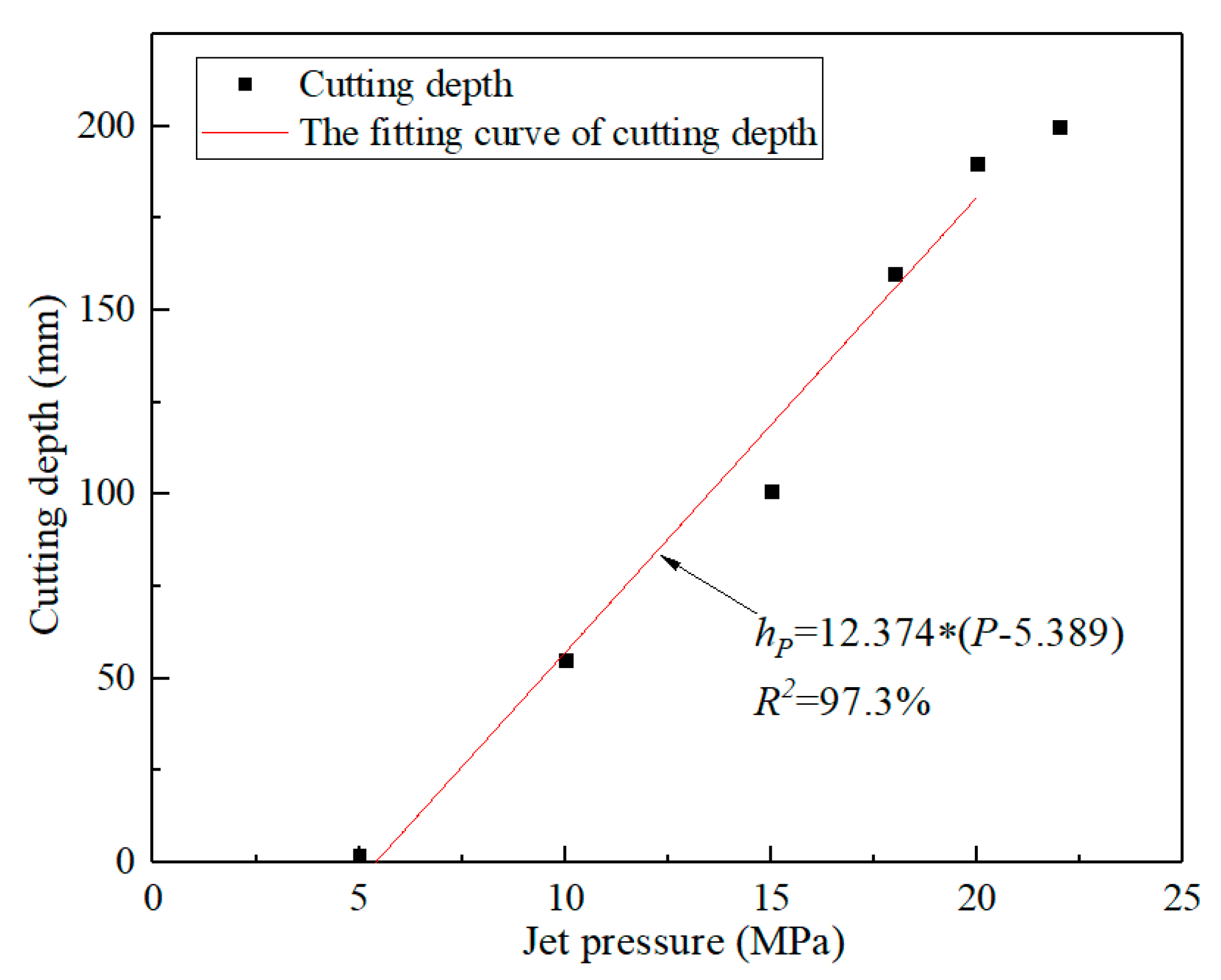
The nozzle diameter determines the flow rate of the water jet and affects the impact energy to a certain extent, as expressed by Equations (5) and (6) [27]. As the nozzle diameter increases, the jet flow rate and impact energy become larger. However, when the nozzle diameter is too large, the jet energy consumption becomes severe, which results in a waste of energy. To improve the impact capacity of the water jet and ensure the smooth discharge of slag during the water jet slotting process, the nozzle diameter should be appropriately increased.
Q = 1 4 π φ v d 2
ω = ρ w π μ d 2 v 3 8 ,
where Q and ω are the jet flow rate and impact kinetic energy, respectively; μ is the flow rate coefficient; v is the water jet velocity; d is the nozzle diameter; and ρw is the water density.
Huang conducted a computational, numeric, fluid dynamics simulation to investigate the influence of nozzle diameter on jet flow characteristics, such as the axial velocity, and the axial dynamic pressure and its attenuation coefficient [28]. As shown in Figure 2, the axial velocities and dynamic pressures of the water jet were obtained with different nozzle diameters. As the nozzle diameter increased, the attenuation coefficient of the jet axial dynamic pressure first decreased and then increased. When the nozzle diameter was 3 mm, the attenuation coefficient was the minimum because the increase of the nozzle diameter affected the attenuation coefficient of the axial dynamic pressure, although the jet energy increased. Moreover, the influence of the nozzle diameter on the slotting depth was not too large. The jet pressure and flow rate of common high-pressure pumps satisfy the requirement for a 3 mm nozzle. Therefore, to investigate the effect of other parameters on the slotting depth, the nozzle diameter was set as a constant of 3 mm.

3.2. Jet Pressure

The relationship between the jet pressure and the jet velocity is expressed by Equation (7). As can be seen, the jet pressure determines the jet velocity and impact energy, and thus affects the slotting depth. To obtain the effect of jet pressure on the slotting depth, water jet cutting experiments were conducted with different jet pressures.
v = φ 2 P ρ w ,
where P is the jet velocity and φ is the nozzle velocity coefficient.
The cutting experiment was conducted on an independently designed and developed water jet test system in the Laboratory of High-pressure Water Jets at Chongqing University, China. The system mainly consisted of a high-pressure pump, pressure and flow control system, and water jet test platform, as shown in Figure 3. The high-pressure pump, manufactured by Nanjing Luhe Coal Mine Machinery Co., Ltd., had a rated pressure of 56 MPa and rated flow rate of 200 L/min. The pressure-flow control system consisted of a pressure sensor of 0–70 MPa with a precision of ±0.1% and an ultrasonic flowmeter of 0.5–20 m/s ± 1%. Additionally, it was convenient to adjust the system pressure and monitor and record the pressure and flow at different times. The water jet test platform was comprised of a translation console and rock bearing system. The translation console had a translational speed of 0.01–1 m/s, and the rock bearing system, with an ultimate bearing weight of 5 t, could move up, down, forward, and backward. Moreover, the nozzle diameter and standoff distance were 3 and 165 mm, respectively. The translation speed was set to a constant of 0.12 m/s. Although it was very difficult to obtain coal blocks with large sizes, the coal block easily split when impacted by the water jet, owing to the typical anisotropy and abundant joints and fissures in the coal. This made it difficult to quantitatively evaluate the jet cutting efficiency. Besides, shaped coal of certain proportions has similar physical and mechanical properties, such as the compressive strength, tensile strength, and Poisson’s ratio, of raw coal. It can well reflect the internal relationship between water jet parameters and rock-breaking efficiency of coal in the experiment [29,30]. Therefore, shaped coals of size 200 × 200 × 200 mm were used as the cutting targets because they were adequately similar to coal; the f coefficient was 0.69.
The cutting experiment results are presented in Figure 4. And the relationship between the jet pressure and the cutting depth can be obtained as shown in Figure 5. When the jet pressure was low, the cutting depth was shallow and approximately equal to zero because the jet pressure was lower than the critical rock-breaking pressure of the water jet. As the jet pressure increased, the cutting depth gradually increased, and the sample was completely cut through at a jet pressure of 22 MPa. As can be seen from the fitting curve, the cutting depth linearly increased with the jet pressure. Therefore, the relationship between the jet pressure and the cutting depth can be expressed as follows:
h P = k 1 ( P P c ) ,
where hP is the cutting depth under different jet pressures; k1 is the proportionality coefficient; and P and Pc are the jet pressure and critical rock-breaking pressure, respectively. The critical rock-breaking pressure could show the effect of the coal strength on slotting depth to a certain extent.

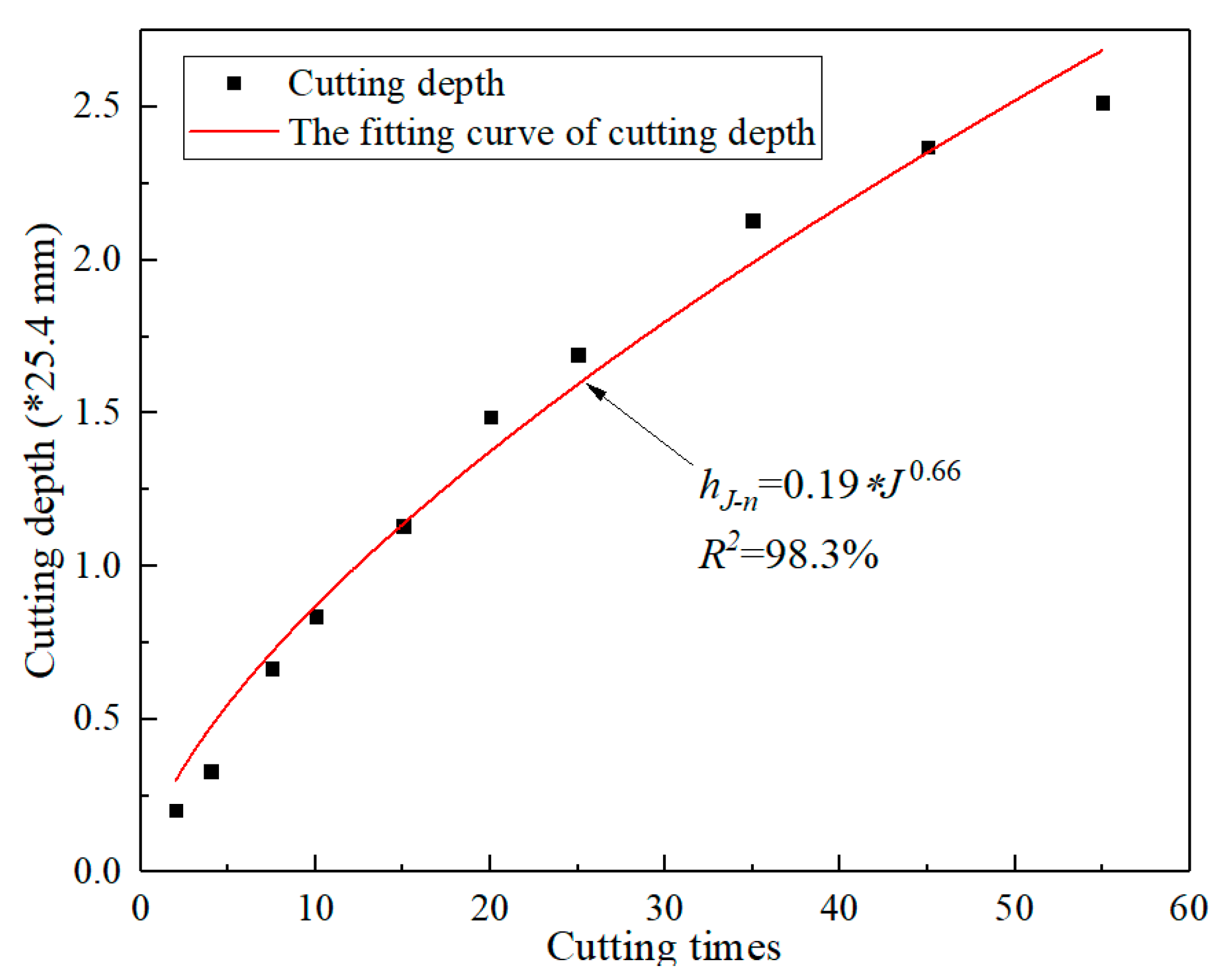
3.3. Rotation Speed and Slotting Time

The water jet slotting in a coal seam is different from conventional moving water jet cutting. First, the nozzles are fixed to the drill bit with their axes perpendicular to the drill bit axis. Then, in the process of water jet slotting, the nozzles rotate along with the drill pipe, and water jets generated by the nozzle impact coal with a rotating trajectory. Finally, a disc-shaped slot is formed. Therefore, the effects of the rotation speed and slotting time on the slotting depth are essentially the effects of the translation speed and cutting times on the cutting depth, respectively. The relationship between the rotation speed and the translation speed is expressed as follows:
n = 30 v T π r
t = J n ,
where n and t are the rotation speed of the drill pipe and slotting time, respectively; vT and J are the translation speed and cutting times of the water jet, respectively; and r is the initial standoff distance of the water jet; that is r = ( D 0 d 0 ) / 2 , where D0 and d0 are the borehole diameter and outer diameter of the slotting device, respectively.
In the cutting experiments at different translation speeds, the nozzle diameter, jet pressure, and standoff distance were 3 mm, 15 MPa, and 165 mm, respectively. The experimental results are presented in Figure 6. The cutting depth decreased as a power function with the increase of the jet translation speed. Additionally, the decrease became progressively smaller. When the translation speed was 60 mm/s, the sample was completely cut through and the cutting depth was more than 200 mm, as shown in Figure 7. This is attributed to the fact that the initial damage of the rock sample occurred in a very short period of a few milliseconds, when the water jet impacted the rock. Subsequently, the impact depth gradually increased. However, when the impact time was excessively long, the high-pressure water accumulated in the slot and formed a water cushion, which weakened the jet impacting capacity. Hence, the cutting depth growth rate decreased as the impact time increased. Equation (11) describes the relationship between the cutting depth and the jet translation speed, as follows:
h v T = k 2 v T α 1 ,
where hvT is the cutting depth at different translation speeds; k2 is the proportionality coefficient; α1 is the index.
The deep slot resulted from multiple high-pressure water jet cuts. Therefore, it was necessary to investigate the effect of cutting times on the total cutting depth. With regard to the cutting times, previous studies have found that the first few cuttings play a major role in jet cutting, and the number of cuttings has a significant impact on the total depth [31]. When the number of cuts increases, the cutting depth slowly increases, but the increment is small. When the cutting number reaches a certain value, the cutting depth is no longer affected. The relationship between the total cutting depth and the cutting times is given in Figure 8. Thus, the relationship between the total cutting depth and the first cutting depth can be expressed as follows:
h J n = h 1 n J α 2 ,
where hJ−n is the total cutting depth at different cutting times; hJ−1 is the cutting depth when the water jet cuts the sample once; α2 is the index.

4. Model for Calculating Water Jet Slotting Depth

By comprehensively considering the influence of the jet pressure, translation speed, and cutting times on the total cutting depth, the cutting depth can be expressed as follows:
h = k v T α 1 J α 2 ( P P c ) ,
where h is the total cutting depth and k is the proportionality coefficient.
By combining Equations (9) and (10), the model for calculating the slotting depth caused by a high-pressure water jet in a coal seam is expressed as follows:
h = k ( n π r 30 ) α 1 ( n t ) α 2 ( p p c ) .
As expressed in Equation (14), the rotation speed has a significant effect on the slotting depth under fixed slotting time. As the rotation speed increases, the slotting depth becomes smaller each time but increases with the slotting repetition. Therefore, there exists an optimal rotation speed for the water jet slotting. This study conducted rotary slotting experiments to determine the relevant parameters in Equation (14) and obtain the optimal rotation speed. As shown in Figure 9, the experimental system mainly was comprised of a high-pressure pump, hydraulic drilling rig, and the sample. The drilling rig, with a rated torque of 1250 N∙m, was used to control the rotation speed in the water jet slotting. The slotting sample was shaped coal with a ratio of coal particle:cement:water = 1:0.5:1, size of 1 × 1 × 1 m, f coefficient of 0.21, and tensile strength of approximately 0.08 MPa.
The experimental procedures are as follows: first, the nozzle diameter and initial standoff distance were set to 3 and 12.5 mm, and the jet pressure was controlled at 10 MPa. Then, the rotation speeds were set to 30, 40, 50, and 60 r/min, respectively. Additionally, the shaped coal sample rotary slotted by a high-pressure water jet and the slotting time was 0.5 min every time. Subsequently, the slotting depth was measured and a slot sample was taken again under the same slotting conditions until the slotting depth did not change. Finally, the rotation speed was changed and the abovementioned process was repeated.
The results are presented in Figure 10. At the same rotation speed, the slotting depth increased with the slotting time, but the growth rate gradually decreased, then tended to be stable, and finally reached a certain limit value. As the rotation speed increased, the slotting depth became greater at the initial period and the limit depth was reached faster. Hence, the slotting depth was the combined result of rotation speed and slotting frequency. Although the relative moving speed was higher at a higher rotation speed, the slotting frequency per time increased, which resulted in deeper slotting depth at the initial period. Moreover, in the process of rotary slotting by the high-pressure water jet, the action mode of the water jet on the coal body changed. Similar to the oscillation effect of the pulsed water jet, the coal body is influenced by the water hammer pressure with periodic frequency, and thus the rock-breaking efficiency improves. In contrast, at lower rotation speed, the impact time of the single slotting coal becomes longer, and the hindrance of the water cushion becomes more severe. Therefore, in the early stages of slotting, the influence of slotting repetitions on the slotting depth is greater than that of a single impact. Increasing the rotation speed contributes to the improvement of the slotting efficiency and slotting depth. However, as the rotation speed increases, the limit slotting depth first increases and then decreases. This indicates that the influence of a single impact on the slotting depth is greater than that of numerous slotting repetitions at the later stages of jet slotting. This is attributed to the fact that the coal body is mainly destroyed by the quasi-static pressure of the water jet.
To verify the proposed slotting depth model, the experimental data were fitted based on Equation (14). The special fitting parameters were given in Equation (15). The fitting degree reached 86%, which indicates that the model established for calculating the slotting depth can be used to describe the relationship between the parameters and the slotting depth. Based on the fitting parameters, the effects of the jet pressure, rotation speed, and slotting time on the slotting depth can be obtained.
h = 0.7873 ( P P c ) n 1.0005 t 0.4891 ln ( n ) + 2.0301 .
Figure 11 shows the fitting curves between the slotting depths and slotting time under the different rotation speeds at the jet pressure of 10 MPa. Thus, to improve the jet slotting depth, the rotation speed should be adopted according to the slotting time. Specifically, when the slotting times are 0–5, 5–10, and 10–15 min, the optimized rotation speeds should be 60, 50, and 40 r/min, respectively. Moreover, as shown in Equation (15), the jet pressure and the threshold rock-breaking pressure of the coal are proportional to the slotting depth. In other words, the jet pressure and threshold pressure only affect the slotting depth magnitude, and have no effect on its changing trend. Therefore, when the jet pressure changes, the relationships between the slotting depth and the rotation speed and slotting time do not change.
According to the abovementioned analysis, the slotting depths under different jet pressures and threshold rock-breaking pressures can be obtained. The tensile strength of coal is typically 0.28–2.25 MPa [32]. Figure 12 shows the predicted slotting depths under the jet pressure of 25 MPa with a tensile strength of 0.5 MPa. The other parameters were as follows: nozzle diameter of 3 mm and initial standoff distance of 12.5 mm. Therefore, the optimized slotting parameters were obtained as follows: when the slotting time was 0–5 min, the optimized rotation speed was 60 r/min; when the slotting time was 5–10 min, the optimized rotation speed was 50 r/min; when the slotting time was 10–15 min, the optimized rotation speed was 40 r/min; when the slotting time was 15–20 min, the optimized rotation speed was 30 r/min and the slotting depth reached 1.9 m.

5. Field Test

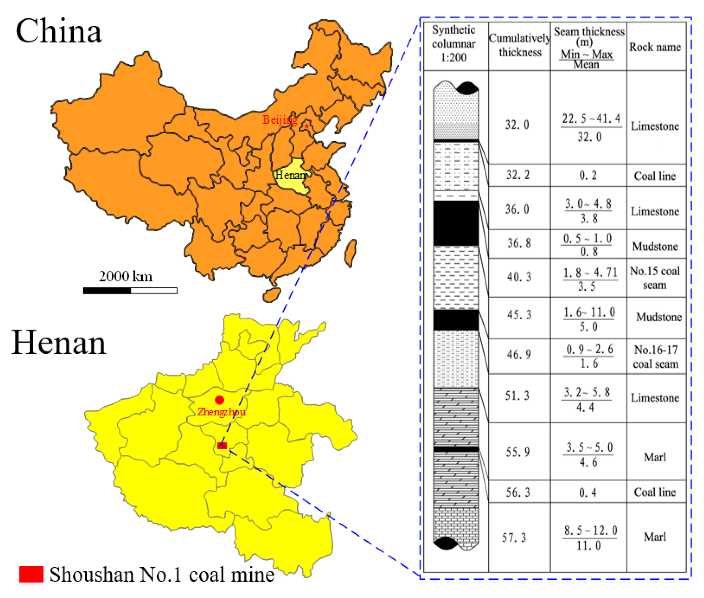
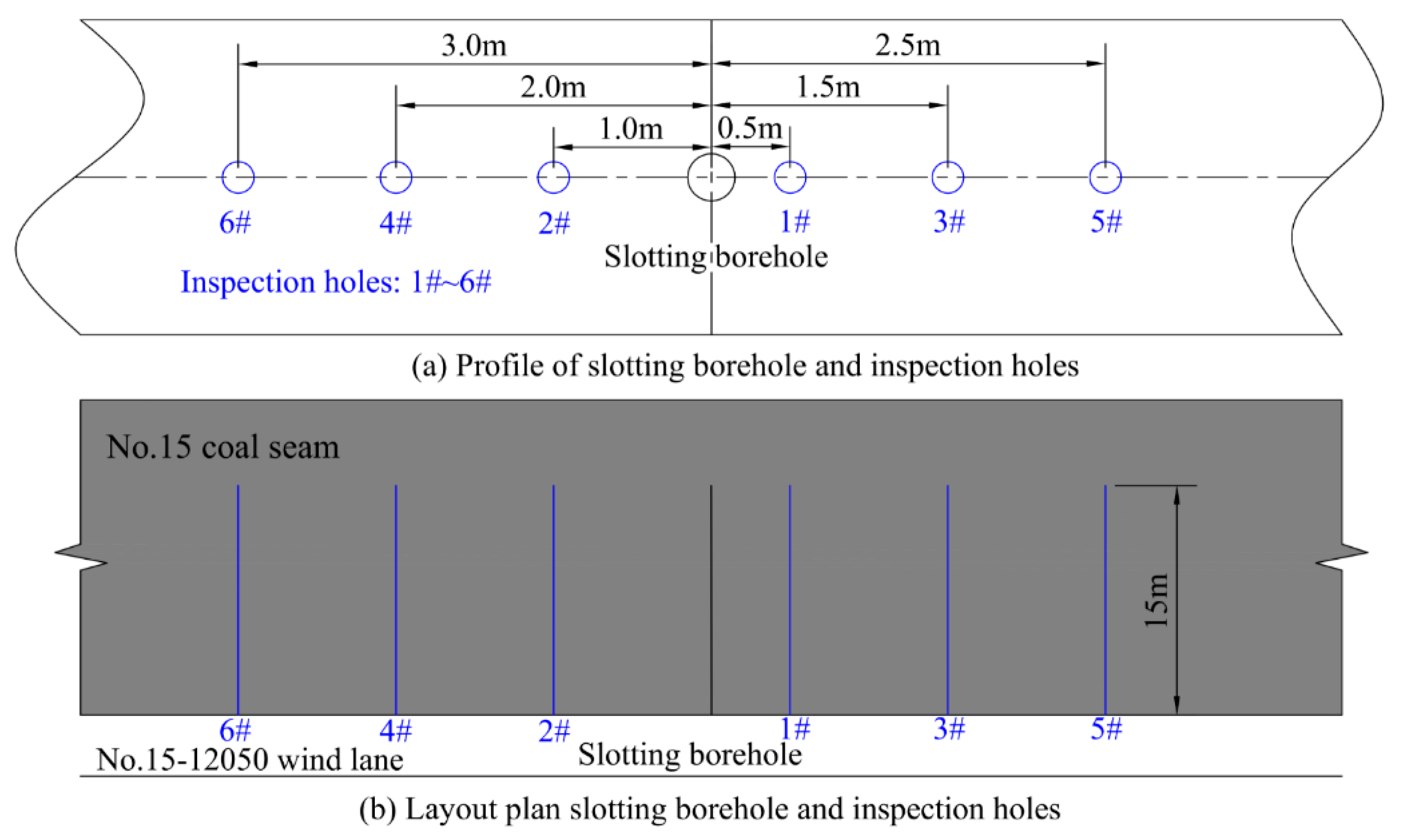
5.1. Test Background

It is known that the slotting depth is more than 1 m when the jet pressure reaches 25 MPa. Therefore, the model for calculating the slotting depth cannot be verified by laboratory experiments when the jet pressure is high. Field tests were carried out to further investigate whether the model could be used in field applications. The high-pressure water jet slotting system was similar to the laboratory slotting experiments. The field test site was the Shoushan Number 1 coal mine affiliated with Pingdingshan Coal Group Co. Ltd., as shown in Figure 13. The field test for the slotting depth investigation was conducted at the Number 15-12050 wind lane. The slotting target coal seam was the Number 15 coal seam, and the hardness coefficient f was 0.13–0.5, which belongs to a soft and crushed coal seam. The tensile strength was 0.2–0.3 MPa.

5.2. Verification of Slotting Depth Model

In the slotting experiments, the jet pressure, borehole diameter, outer slot diameter, and nozzle diameter were set as 25 MPa, 75 mm, 50 mm, and 3 mm, respectively. The slotting borehole depth was 15 m. As shown in Figure 14, the number 1, number 3, and number 5 inspection holes were arranged at the right of slotting borehole with a distance of 0.5 m, 1.5 m, and 2.5 m from the slotting borehole, respectively. On the left side, the number 2, number 4, and number 6 inspection holes were arranged at distances of 1, 2, and 3m, respectively. The depths and diameters of all inspection holes were 15 m and 42 mm, respectively. The inclination dip of all boreholes was 15°. The slotting position of the high-pressure water jet was located 14 m away from the slotting borehole. Four groups of slotting tests were conducted. The rotation speed and slotting time in the high-pressure water jet slotting were n = 60 r/min and t = 5 min, n = 50 r/min and t = 10 min, n = 40 r/min and t = 15 min, and n = 30 r/min and t = 20 min, respectively.
The slotting depth was estimated by observing whether water flowed out from the inspection hole. The results are presented in Table 1. Under the test conditions of n = 60 r/min and t = 5 min, water flowed out from the number 1 and 2 inspection holes but not out of the number 3–6 holes. This indicates that the slotting depth was more than 1.0 m but less than 1.5 m, which is consistent with the depth predicted based on Equation (14). The results of the other three test groups were similar, which indicates that the proposed model for calculating the slotting depth is reliable and can be used in field applications.

6. Conclusions

This study investigated the effects of the nozzle diameter, jet pressure, rotation speed, and slotting time on the cutting depth. A model for calculating a slotting depth suitable for field application was established, and optimized slotting parameters were obtained. Based on water jet slotting field tests, the proposed calculation model was verified. The following conclusions were drawn from this study:
(1)
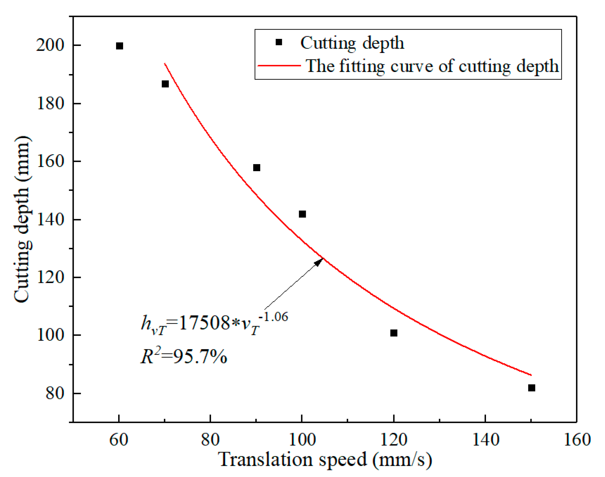
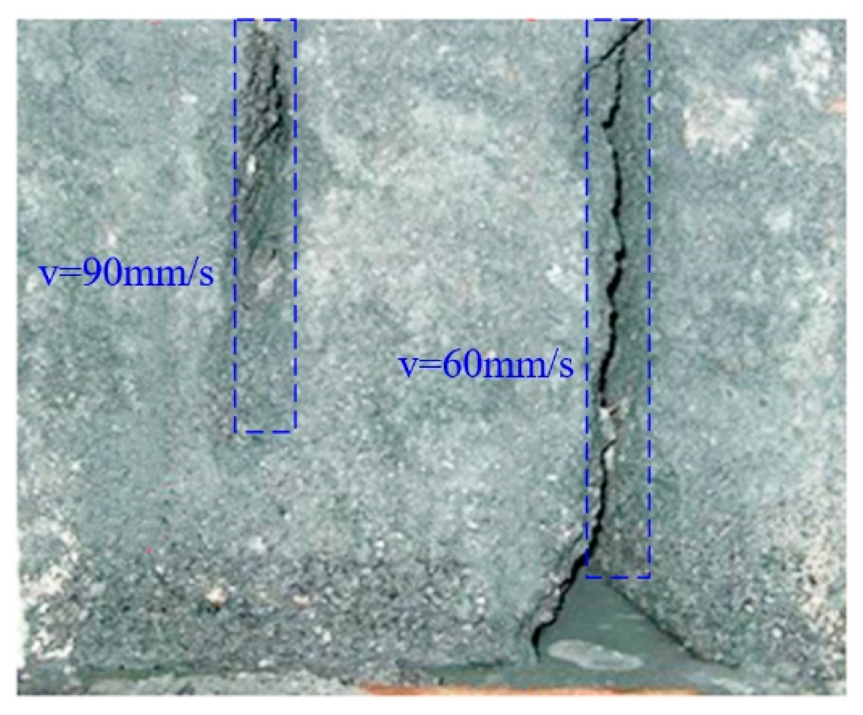
The attenuation coefficient of the jet axial dynamic pressure first decreased and then increased with the increase of the nozzle diameter. For a much higher jet impact velocity, there existed an optimal nozzle diameter. Additionally, the cutting depth linearly increased with the jet pressure and decreased as a power function with the increase of the jet translation speed. Moreover, the number of cuttings had a significant impact on the cutting depth, and the several previous cuttings played a major role in the jet cutting. With the further increase of cutting times, the cutting depth slowly increased, but the increment was small.
(2)
Water jet slotting experiments were conducted with different rotation speeds and slotting times. The results revealed that the slotting depth increased with the slotting time, but the growth rate gradually decreased and tended to be stable. As the rotation speed increased, the slotting depth became greater at the initial period, and the limit depth was reached faster. At the early slotting stages, more slotting repetitions were helpful in increasing the slotting depth. At the later slotting stages, a longer single impact improved the slotting efficiency.
(3)
A model for calculating the water jet slotting depth was established according to the effects of key parameters on the cutting depth. This model was subsequently verified using the rotatory slotting experiment data, and the results revealed that the fitting was good. Based on the proposed model, the slotting depths under different jet pressures and the threshold rock-breaking pressures were calculated.
(4)
Water jet slotting field tests were carried out. The slotting depths at different rotation speeds with different slotting times were analyzed. Comparisons with the depths predicted by the calculation model were made, which revealed that the differences are acceptable.

Author Contributions

J.Z., Y.W., Z.G., and S.X. contributed to conceiving and designing the experiments, analyzing the data, and writing the paper. H.Z. and X.H. performed the experiments.

Funding

This research was funded by the National Natural Science Foundation of China, grant numbers 51504046, 51774055, and the National Science and Technology Major Projects of China, grant number 2016ZX05045.

Acknowledgments

We thank Liwen Bianji, Edanz Editing China (www.liwenbianji.cn/ac), for editing the English text of a draft of this manuscript.

Conflicts of Interest

The authors declare no conflict of interest.

References

  1. Liu, T.; Lin, B.Q.; Yang, W.; Zou, Q.L.; Kong, J.; Yan, F.Z. Cracking process and stress field evolution in specimen containing combined flaw under uniaxial compression. Rock Mech. Rock Eng. 2016, 49, 3095–3113. [Google Scholar] [CrossRef]
  2. Liu, S.M.; Harpalani, S. Permeability prediction of coalbed methane reservoirs during primary depletion. Int. J. Coal Geol. 2013, 113, 1–10. [Google Scholar] [CrossRef]
  3. Lu, Y.Y.; Xiao, S.Q.; Ge, Z.L.; Zhou, Z.; Ling, Y.F.; Wang, L. Experimental study on rock-breaking performance of water jets generated by self-rotatory bit and rock failure mechanism. Powder Technol. 2019, 346, 203–216. [Google Scholar] [CrossRef]
  4. Xiao, S.Q.; Ge, Z.L.; Lu, Y.Y.; Zhou, Z.; Li, Q.; Wang, L. Investigation on coal fragmentation by high-velocity water jet in drilling: Size distributions and fractal characteristics. Appl. Sci. 2018, 8, 1988. [Google Scholar] [CrossRef] [Green Version]
  5. Hu, S.S.; Cheng, Y.Q. Discussions on key development fields of China’s coal science and technology at early stage of 21st century. J. China Coal Soc. 2005, 30, 1–7. [Google Scholar]
  6. Ge, Z.L.; Mei, X.D.; Jia, Y.J.; Lu, Y.Y.; Xia, B.W. Influence radius of slotted borehole drainage by high pressure water jet. J. Min. Saf. Eng. 2014, 31, 657–664. [Google Scholar]
  7. Lin, B.Q.; Lv, Y.C.; Li, B.Y.; Zhai, C. High-pressure abrasive hydraulic cutting seam technology and its application in outbursts prevention. J. China Coal Soc. 2007, 32, 959–963. [Google Scholar]
  8. Shen, C.M.; Lin, B.Q.; Zhang, Q.Z. Induced drill-spray during hydraulic slotting of a coal seam and its influence on gas extraction. Int. J. Min. Sci. Technol. 2012, 22, 785–791. [Google Scholar] [CrossRef]
  9. Lin, B.Q.; Yan, F.Z.; Zhu, C.J.; Zhou, Y.; Zou, Q.L.; Guo, C.; Liu, T. Cross-borehole hydraulic slotting technique for preventing and controlling coal and gas outbursts during coal roadway excavation. J. Nat. Gas. Sci. Eng. 2015, 26, 518–525. [Google Scholar] [CrossRef]
  10. Yu, H.; Lu, T.K. Research on high pressure water jet cutting to improve gas drainage efficiency. Coal Sci. Technol. 2009, 37, 48–50. [Google Scholar]
  11. Zhang, Q.Z.; Lin, B.Q.; Meng, F.W.; Shen, C.M. Research and application on disturbance influence law of seam slot cutting with high pressurized water jet. Coal Sci. Technol. 2011, 39, 49–52. [Google Scholar]
  12. Shen, C.M.; Lin, B.Q.; Wu, H.J. High-pressure water jet slotting and influence on permeability of coal seams. J. China Coal Soc. 2011, 36, 2058–2063. [Google Scholar]
  13. Lu, Y.Y.; Ge, Z.L.; Li, X.H.; Chen, J.F.; Liu, Y. Investigation of a self-excited pulsed water jet for rock cross-cutting to uncover coal. J. China Univ. Min. Technol. 2010, 39, 55–58. [Google Scholar]
  14. Lu, Y.Y.; Jia, Y.J.; Ge, Z.L.; Xia, B.W. Coupled fluid-solid model of coal bed methane and its application after slotting by high-pressure water jet. J. China Univ. Min. Technol. 2014, 43, 23–29. [Google Scholar]
  15. Tang, J.R.; Lu, Y.Y.; Ouyang, M.D.; Zhang, W.F.; Zhang, X.W. Optimal design and performance evaluation of a new hydrajet-fracturing nozzle. J. China Univ. Petrol. 2015, 39, 72–78. [Google Scholar]
  16. Lu, Y.Y.; Ge, Z.L.; Tang, J.R. A Multi-Functional Self-Oscillating Abrasive Water Jet Generator. Patent CN102133562A, 28 January 2011. [Google Scholar]
  17. Xu, Y.P.; Lin, B.Q.; Zhu, C.J.; Liu, Y. The dynamic characteristic of abrasive and its parameter optimization based on the drilling-cutting integration of high-pressure abrasive water jet. J. Min. Saf. Eng. 2011, 28, 623–627. [Google Scholar]
  18. Lu, Y.; Huang, F.; Liu, X.C.; Ao, X. On the failure pattern of sandstone impacted by high-velocity water jet. Int. J. Impact Eng. 2015, 76, 67–74. [Google Scholar] [CrossRef]
  19. Dehkhoda, S.; Hood, M. An experimental study of surface and sub-surface damage in pulsed water-jet breakage of rocks. Int. J. Rock Mech. Min. Sci. 2013, 63, 138–147. [Google Scholar] [CrossRef]
  20. Momber, A.W. The response of geo-materials to high-speed liquid drop impact. Int. J. Impact Eng. 2016, 89, 83–101. [Google Scholar] [CrossRef]
  21. Field, J.E.; Lesser, M.B.; Dear, J.P. Studies of two-dimensional liquid-wedge impact and their relevance to liquid-drop impact problems. Proc. R. Soc. Lond. A 1985, 401, 225–249. [Google Scholar] [CrossRef]
  22. Lesser, M.B. Analytic solutions of liquid-drop impact problems. Proc. R. Soc. Lond. A 1981, 377, 289–308. [Google Scholar] [CrossRef]
  23. Lesser, M.B.; Field, J.E. The impact of compressible liquids. Annu. Rev. Fluid Mech. 1983, 15, 97–122. [Google Scholar] [CrossRef]
  24. Rehbinder, G. Some aspects on the mechanism of erosion of rock with high speed water jet. In Proceedings of the Third International Symposium on Jet Cutting Technology, BHRA Fluid Engineering, Chicago, IL, USA, 11–13 May 1976. Paper No E1. [Google Scholar]
  25. Rehbinder, G. Erosion resistance of rock. In Proceedings of the Fourth International Symposium on Jet Cutting Technology, BHEA Fluid Engineering, Kent, UK, 12–14 April 1978. Paper No E1. [Google Scholar]
  26. Hashish, M.; Duplessis, M.P. The application of generalized jet-cutting equation. In Proceedings of the Fourth International Symposium on Jet Cutting Technology, BHEA Fluid Engineering, Ken, UK, 12–14 April 1978. Paper No E1. [Google Scholar]
  27. Xue, S.X. High. Pressure Water Jet Technology and Engineering; Hefei University of Technology Press: Hefei, China, 2006. [Google Scholar]
  28. Huang, X.B. Critical Parameters of High-Pressure Water Jet Slotting in Coal Seam. Master’s Thesis, College of Resources and Environment Science, Chongqing University, Chongqing, China, 2012. [Google Scholar]
  29. Zuo, B.C.; Chen, C.X.; Liu, C.H.; Shen, Q.; Xiao, G.F.; Liu, X.W. Research on similar material of slope simulation experiment. Rock Soil Mech. 2004, 11, 1805–1808. [Google Scholar]
  30. Li, H.C. Similar Simulation Test of Mine Pressure; China University of Mining and Technology Press: Xuzhou, China, 1988. [Google Scholar]
  31. Shen, Z.H. Theory and Technology of Water Jet; University of Petroleum Press: Dongying, China, 1998. [Google Scholar]
  32. Li, X.W. Mechanical Properties of Rock Blocks; Coal Industry Publishing House: Beijing, China, 1983. [Google Scholar]
Figure 1. Technical sketch of coal seam permeability improvement by water jet slotting. (a) is the process of high-pressure water jet slotting in coal seams; (b) is the crack condition surrounding the slots.
Applsci 09 05250 g001
Figure 2. (a) Axial velocity and (b) axial dynamic pressure of a water jet with different nozzle diameters [28].
Applsci 09 05250 g002
Figure 3. System used in cutting experiment.
Applsci 09 05250 g003
Figure 4. Comparison of cutting depth subjected to high-pressure water jet with different jet pressures.
Applsci 09 05250 g004
Figure 5. The effect of jet pressure on cutting depth.
Applsci 09 05250 g005
Figure 6. The effect of translation speed on cutting depth.
Applsci 09 05250 g006
Figure 7. Cutting depths from a high-pressure water jet with different translation speeds.
Applsci 09 05250 g007
Figure 8. The effect of cutting times on cutting depth [31].
Applsci 09 05250 g008
Figure 9. System used in experiment of rotary slotting by water jet.
Applsci 09 05250 g009
Figure 10. Slotting depth at different rotation speeds.
Applsci 09 05250 g010
Figure 11. Fitting curves between slotting depth and slotting time at different rotation speeds under jet pressure of 10 MPa.
Applsci 09 05250 g011
Figure 12. Prediction curves of slotting depth versus slotting time at different rotation speeds under jet pressure of 25 MPa.
Applsci 09 05250 g012
Figure 13. Site of water jet slotting field test: Shoushan Number 1 coal mine affiliated with Pingdingshan Coal Group Co. Ltd.
Applsci 09 05250 g013
Figure 14. Layout of slotting borehole and inspection holes.
Applsci 09 05250 g014
Table 1. Results of water jet slotting in coal seam under different test conditions (rotation speed and slotting time).
NumberTest ConditionWhether There is Water Flowing Out from Inspection Hole or NotSlotting Depth (m)Prediction Depth (m)
1n = 60 r/min, t = 5 min1#~2#: Yes, 3#~6#: No1.0~1.5 m1.37 m
2n = 50 r/min, t = 10 min1#~2#: Yes, 4#~6#: No
3#: a little water
1.0~1.5 m, close to 1.5 m1.48 m
3n = 40 r/min, t = 15 min1#~3#: Yes, 4#~6#: No1.5~2.0 m1.69 m
4n = 30 r/min, t = 20 min1#~3#: Yes, 5#~6#: No
4#: a little water
1.5~2.0 m, close to 2.0 m1.91 m

