A Study on a Mechanism of Lateral Pedestrian-Footbridge Interaction


1
School of Transportation and Civil Engineering &Architecture, Foshan University, Foshan 528225, China
2
School of Civil Engineering, Guangzhou University, Guangzhou 510006, China
3
Department of Civil and Environmental Engineering, The Hong Kong Polytechnic University, Hong Kong 999077, China
*
Author to whom correspondence should be addressed.
Appl. Sci. 2019, 9(23), 5257; https://0-doi-org.brum.beds.ac.uk/10.3390/app9235257
Submission received: 4 November 2019
/
Revised: 23 November 2019
/
Accepted: 27 November 2019
/
Published: 3 December 2019
(This article belongs to the Special Issue Bridge Dynamics)
Abstract
:Based on the pedestrian lateral force hybrid Van der Pol/Rayleigh model, this study investigates the interaction dynamic model of a pedestrian-flexible footbridge lateral coupling system. A multi scale method is adopted to decouple the equation. The paper also studies the nonlinear dynamic response of the pedestrian-footbridge coupling system as well as the relationship between the lateral displacement of pedestrians and flexible footbridges, and the lateral interaction of the two variables. The results show that with the same frequency tuning parameters, when the mass ratio of pedestrians and footbridges is very small, the larger the mass ratio is, the larger the lateral response amplitude of pedestrians becomes. Conversely, when the mass ratio of pedestrians and footbridges is much larger, the larger the mass ratio is, the smaller the response amplitude becomes. When the natural frequency of a footbridge is larger, its Phase Angle becomes larger. As the lateral amplitude of pedestrians increases, the Phase Angle approaches zero. Moreover, regarding the variation of the Phase Angle between the interaction force and footbridge lateral vibration speed based on the lateral relative displacement of pedestrians, of which the variation range is (0, ), as the pedestrians’ lateral amplitude increases, the Phase Angle approaches −. The dynamic load coefficient varies linearly with the lateral amplitude of pedestrian vibrations.
1. Introduction
The vertical vibrations of a pedestrian-footbridge coupling have attracted considerable and increasing attention [1,2,3,4,5]. A new single DOF (degree of freedom) model of a bipedal pedestrian is proposed to study the dynamic interaction between a footbridge and pedestrians [6]. Li Q et al. [7] simulated crowd-footbridge interactions based on a multi free mass-damping coupling system. In line with the work of Federica Tubino [8], the probability assessment method is applied to study the interaction between the vertical vibrations of multiple pedestrians and a footbridge. In a study by Li Shoutao [9], a three-degree-of-freedom human-structure interaction model was established to study the system resonance frequency. Comparing the existing experimental results, it was found that the tandem three-degree-of-freedom human model is closer to the experimental results. A new biodynamic synchronized coupled model is based on a measured footbridge on a comparative basis [10]. In a study by Zhang M et al. [11], pedestrian excitation was considered to model the structure-human body model-damping of Phase Angle interactions based on biomechanics. Hamill J et al. [12] established a model of pedestrians’ movements based on biomechanics. Zhou Chen et al. [13] studied the parameter vibration responses while considering the time-lag effect by taking the Millennium Bridge in London as an example, which shows that the time-lag has no effect on the amplitude of the parameter vibration response. Belykh, Igor et al. [14] discussed parameter variation trends that were used to obtain coupled pedestrian-bridge oscillations, notably the influence of the mass ratio of pedestrians to the bridge mass in the mode considered, and the phase variation with the amplitude.
However, there are few studies that have been conducted on lateral coupled pedestrian-footbridge vibrations. Macdonald, SP Carrol, and M. Bocian considered pedestrians using a linear inverted pendulum model and studied the changes in parameters such as mass, damping, and force in the case of pedestrian-footbridge laterally coupled vibrations [15,16,17]. Among these studies, most researchers did not highlight the importance of pedestrians’ vibration responses, but simply focused on the vibration responses of the footbridge. Some scholars did not analyze the decoupling work of pedestrian-footbridge coupling systems when studying pedestrian-footbridge coupling vibrations [18]. Instead, the vibration of the footbridge was regarded as a vibration table in their studies. Its vibration amplitude and frequency were assumed to be a constant value [18]. In this case, this assumption is not reasonable because the lateral vibration response of pedestrians and footbridges interacts mutually. However, if the coupling is weak, it is reasonable to assume that the amplitude and frequency of the footbridge are constant. When the lateral swaying frequency of pedestrians and lateral vibration of the footbridge are the same or similar, the coupled vibration between pedestrians and the footbridge is strongly coupled. Moreover, both have a major influence on each other. The pedestrian-footbridge system resonance effect cannot be presented because the vibration amplitude and frequency of the footbridge are simply considered as being constant. Silvano Erlicher et al. [19,20] adopted a modified hybrid Van der Pol/Rayleigh model to simulate the lateral forces of pedestrians on periodic moving floors and rigid floors, respectively.
Therefore, based on a lateral force model of the hybrid Van der Pol/Rayleigh model proposed in their paper, the lateral interaction dynamic model of pedestrian-flexible footbridge coupling system was established. By decoupling the coupling equation, it derives the amplitude-frequency curve of pedestrians and pedestrian bridges. The paper also studies the lateral displacement and lateral force between pedestrians and footbridges. Finally, the study obtains a dynamic response of interactions between pedestrians and footbridges through an example.
2. A Dynamic Model of Lateral Pedestrian-Footbridge Interaction
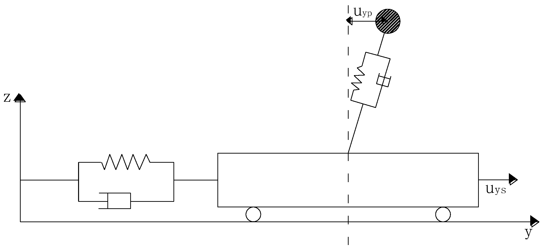
A pedestrian is considered using an inverted pendulum model with the dynamic feature of the hybrid Van der Pol/Rayleigh model, where the coupling pedestrian-footbridge vibration is presented in Figure 1. When pedestrians walk on the footbridge, the footbridge is vibrated by the pedestrians, generating vibrations. The footbridge responds correspondingly according to the pedestrians’ vibrations. In addition, the pedestrians will make timely adjustments according to the vibrations of the footbridge. Therefore, the movement of the pedestrian consists of two parts: one is the lateral movement of the pedestrians relative to the footbridge, and the other is the lateral movement of the footbridge. The lateral movement of pedestrians is the sum of the two parts . Thus, when considering the pedestrian-footbridge interaction, its lateral dynamic equation is as follows:
The external force induced by walking pedestrians is loaded on the footbridge. As a result, the lateral dynamic equation of the footbridge is:
In the above equation, is the pedestrians’ center of gravity relative to the lateral vibration displacement of the footbridge. is the lateral vibration displacement of the footbridge. is the modal mass of the footbridge. is the mass of a single pedestrian. is the force loading on the footbridge structure when the pedestrians are walking. In general, Equations (1) and (2) are the dynamic equations of the pedestrian-footbridge interaction. They are coupled by the pedestrian-footbridge interaction force (related to the speed and displacement of pedestrians). It can be interpreted that Equations (1) and (2) are the lateral coupling dynamic equations of the pedestrian-bridge interaction. For the pedestrian system, the additional effect due to the movement of the footbridge is the external force. For the footbridge system, the excitation force generated by the movement of pedestrians is the external force.
3. Study on Dynamic Response of Pedestrian-Footbridge Interactions
3.1. Dynamic Coupling Equation Solution of the Lateral Interaction Pedestrian-Footbridge
The multiscale method is used to solve Equations (1)–(3). Assume that the nonlinear systems (1)–(3) are weak nonlinear systems. Then, a small parameter is added to the damping term, external excitation term, and nonlinear term in the system. Thus, Equations (1)–(3) can be written as:
It is assumed that the first-order approximate solutions of Equations (4) and (5) are:
of which and .
Equations (6) and (7) are substituted into Equations (4) and (5) by adopting the multiscale method, aiming to achieve a situation where the coefficients of the small parameters and on both sides are equal. Then, the following partial differential equations can be defined as follows:
Assume that the solution of Equation (8) is obtained as follows:
With regard to Equations (10) and (11), is the conjugate complex number of the preceding expressions. Equations (10) and (11) are inserted into Equation (9) to derive:
It can be seen shown, according to the right-hand sides of Equations (12) and (13), that the terms containing and cause secular terms to occur in the solutions of Equations (12) and (13), respectively. Suppose that ; the solution of Equations (12) and (13) will generate secular terms, indicating that the internal resonance phenomenon is presented in the pedestrian-bridge bridging system in the case of .
3.2. Internal Resonance Analysis of Pedestrian-Footbridge Lateral Coupling System
The pedestrians’ lateral walking frequency and the natural frequency of the footbridge are assumed to satisfy:
Regarding Equation (14), where refers to the frequency tuning parameter, supposing the coefficient of the secular term is zero, associated with Equations (12) and (13), the following can be derived:
To facilitate the calculation, it is assumed that the phase of the footbridge is zero. Because the main focus here is on the Phase Angle between pedestrians and the footbridge, is written in qn exponential form; hence, one can easily obtain:
Equations (17) and (18) are substituted into Equations (15) and (16); thus, Equations (15) and (16) become:
If the coefficients of the real part and imaginary part of Equations (19) and (20) are zero, respectively, then in this case, one obtains:
Hence, Equations (21)–(24) can be rewritten as follows in the assumption of :
To obtain the amplitude frequency equation of pedestrians and the footbridge structure as well as the Phase Angle of displacements for pedestrians and the footbridge, it is assumed that , , and are the equations for which the amplitude and Phase Angle are satisfied. Subsequently, one obtains:
Equations (29)–(32) can be rewritten as follows. If , one obtains the following equations:
Multiplying Equations (33) and (34) and then adding them both together leads to:
Similarly, Equations (35) and (36) are multiplied, and then both of them are added together. The resulting equation can be defined as follows:
Equations (37) and (38) are jointly connected to decouple the lateral amplitude of pedestrians and footbridges, for which the amplitude frequency equation of pedestrians’ lateral vibration can be derived as:
With respect to Equations (33) and (34), the Phase Angle between the lateral relative pedestrians’ displacement and lateral vibration displacement of the footbridge is derived as:
It can be concluded from Equation (40) that when the pedestrians’ lateral walking frequency is consistent with the vibration frequency of the footbridge, that is, when the resonance occurs, the Phase Angle between the pedestrians’ relative displacement and the vibration displacement of the footbridge tends to ±90°.
In detail, the amplitude of a pedestrian’s lateral vibration is derived according to Equation (39), and then the lateral vibration amplitude of the pedestrian bridge is determined based on Equation (38). Assuming:
Equation (39) can be simplified as:
4. Amplitude Frequency Curve
4.1. Amplitude Frequency Curve of Pedestrians
Equation (42) is related to the unary cubic equation , which has a zero solution only, while the rest are related to the unary quadratic equation . Hence, its discriminate can be rewritten as:
For convenience of the following analysis, the modal mass ratio parameters of pedestrians and the footbridge are defined as:
If , then , or if , Equation (42) has a zero solution and two equal real roots, namely, and . Therefore, the pedestrians’ amplitude frequency curve equation becomes:
If , then , and if , or if or even , then Equation (42) has a zero solution and two equal real roots, namely, and . Thus, the pedestrians’ amplitude frequency curve equation can be derived:
Equations (45) and (47) are trivial solutions for the pedestrians’ lateral vibration, while Equations (46) and (48) are nontrivial solutions for the pedestrians’ lateral vibration. Equation (46) implies that in the case where or , the pedestrians’ lateral vibration is related only to the pedestrians’ parameters. Moreover, according to Equation (48), it is indicated that the pedestrians’ lateral amplitude is related to the modal mass ratio, the pedestrians’ parameters, and the damping of the footbridge.
4.2. Amplitude Frequency Curve of Footbridge
According to Equation (38), if , , then it can be illustrated that the lateral vibration displacement of pedestrians and the lateral vibration displacement of the footbridge are both 0, which is the trivial solution of the footbridge.
Equation is inserted into Equation (38) with the assumption that ; as a result, one gets
When equation is inserted into Equation (38) in the case of , we can obtain:
Here, Equation (49) can be regarded as a trivial solution for the lateral vibration of the footbridge, and Equations (50) and (51) are nontrivial solutions for the lateral vibration of the footbridge.
Therefore, the first approximate solution of the lateral steady-state response of the pedestrians and footbridge is written as:
5. Study on Pedestrian-Footbridge Lateral Displacement and Lateral Interaction
5.1. The Phase Angle between the Lateral Relative Displacement of Pedestrians and Lateral Displacement of the Footbridge
In Equation (40), is the Phase Angle between the lateral relative displacement of pedestrians and the lateral displacement of the footbridge. Assuming , the lateral absolute displacement of pedestrians lags behind the lateral displacement of the footbridge; if , the lateral absolute displacement of pedestrians is ahead of the lateral displacement of the footbridge; the amount of time lagging behind or in advance of is shown in the equation . The relationship between Phase Angle and frequency tuning parameters can be derived as follows based on Equation (34):
The phase angle is located at . Figure 2 presents the difference between pedestrians’ lateral walking frequency and the footbridge fundamental frequency (frequency tuning parameters). It also shows the impact of the difference on the Phase Angle between pedestrians and the footbridge in the case of different amplitude ratios. According to Figure 3, when pedestrians’ lateral walking frequency tends towards the fundamental frequency of the footbridge, the corresponding Phase Angle approaches . Taking Newland’s study into account, it can be concluded that the range of Phase Angles between pedestrians and footbridge motion is limited to degree. In addition, the phase angle at resonance is . The results deduced in the paper are in accordance with the results based on the Newland model [18]. In Abrams’ study of the Millennium Bridge, it is concluded that the Phase Angle of pedestrians with regard to the footbridge is , which is similar to the results found in this paper [21].
First, in the case where pedestrians’ lateral walking frequency is consistent with the lateral fundamental frequency of the footbridge, that is, in the case of , while considering Equation (54), it can be proven that and . Thus, is inserted into Equation (35), after which we can obtain:
Taking Equation (54) into consideration, it can be derived that ; thus, , = 0, ±1, ±2, ±3, …, which is consistent with the above results based on the relationship between the Phase Angle and frequency tuning parameters. Therefore, if , then ; if , then the pedestrians’ vibration response is ahead of the footbridge response, with the amount of time in advance of the footbridge response shown as . When the pedestrians walk along the footbridge, the amount of time before the footbridge’s response is represented as . For , the pedestrians’ vibration response lags behind the footbridge’s response, with the lag time ; when the pedestrians walk on the footbridge, the lag time becomes .
5.2. Phase Angle between the Lateral Absolute Displacement of Pedestrians and the Lateral Displacement of the Footbridge
With regard to resonance, the vibration frequency caused by pedestrians is the same as that of footbridges but differs in phase. The absolute displacement of pedestrians is the sum of the pedestrians’ relative displacement and the footbridge structure displacement, which results in an absolute displacement of pedestrians of:
Therefore, the absolute displacement amplitude is defined as:
After considering and then , we can differentiate the Equation in (58):
The Phase Angle between the absolute displacement of pedestrians and the footbridge displacement is expressed in Equation (59):
Equations (37), (54), and (55) are inserted into Equation (59). This leads to:
From Equation (58), it can be known that the absolute displacement amplitude of pedestrians is related to the following parameters: lateral response amplitude of the footbridge, relative displacement of pedestrians, Phase Angle, frequency difference, and the time of footbridge displacement, which in turn has nothing to do with the mass of the footbridge and pedestrians. Consider that the parameters are constant, including the lateral response amplitude of the footbridge, the relative displacement of pedestrians and the Phase Angle, frequency difference, and time of footbridge displacement. In this case, the absolute displacement amplitude of pedestrians is linear with respect to the response amplitude. In addition, the larger the amplitude of the footbridge response is, the larger the absolute displacement amplitude of pedestrians becomes.
When , the absolute displacement of pedestrians lags behind the displacement of the footbridge. Conversely, in the case of , the absolute displacement of pedestrians is ahead of the footbridge displacement.
5.3. Phase Angle between Lateral Interaction Force and Lateral Excitation Speed
When the pedestrians’ lateral walking frequency is not equal to the fundamental frequency of the footbridge, the interaction force can be presented as:
Because , in this case ; hence, Equation (61) can be written as:
The lateral dynamic amplitude of pedestrians on the footbridge is defined as:
Equation (37) is inserted in Equation (63) to easily obtain:
As a result, the lateral dynamic coefficient is presented as:
The phase angle between the interaction force and vibration displacement of the footbridge can be computed as:
Equations (37), (54), and (55) are substituted into Equation (66), and the following equation holds:
Since the lateral vibration displacement of the footbridge is expressed as , the lateral vibration speed of the footbridge becomes:
Hence, the Phase Angle between the pedestrian-footbridge interaction force and the lateral vibration speed of the footbridge is:
Therefore, it can be proven that the lateral interaction force amplitude and the dynamic load coefficient are related to the relative lateral response amplitude of pedestrians, pedestrians’ parameters, walking frequency, and frequency differences but have nothing to do with the mass of the footbridge. When these parameters are considered to be constant, in this case, the dynamic load coefficient is linear with respect to the amplitude of the pedestrian lateral response. Based on this, the larger the response amplitude is, the larger the dynamic load coefficient becomes, which is proven to be the main principle of pedestrian-footbridge interactions.
It is assumed that when , the lateral interaction force lags behind the response of the footbridge; conversely, when , the lateral interaction force is ahead of the pedestrians’ response.
6. Case Analysis
The amplitude-frequency curve and Phase Angle of pedestrians are calculated separately in different situations. It is assumed that the damping ratio of the footbridge structure is 0.005. In the reference [22], the parameters of the hybrid Van der Pol/Rayleigh model are obtained according to the experimental values and the least squares method, and the parameters are verified. Therefore, the parameters of pedestrians are taken as two groups: the first group includes , , , and ; the second group includes , , , and [22].
6.1. Amplitude Frequency Curve
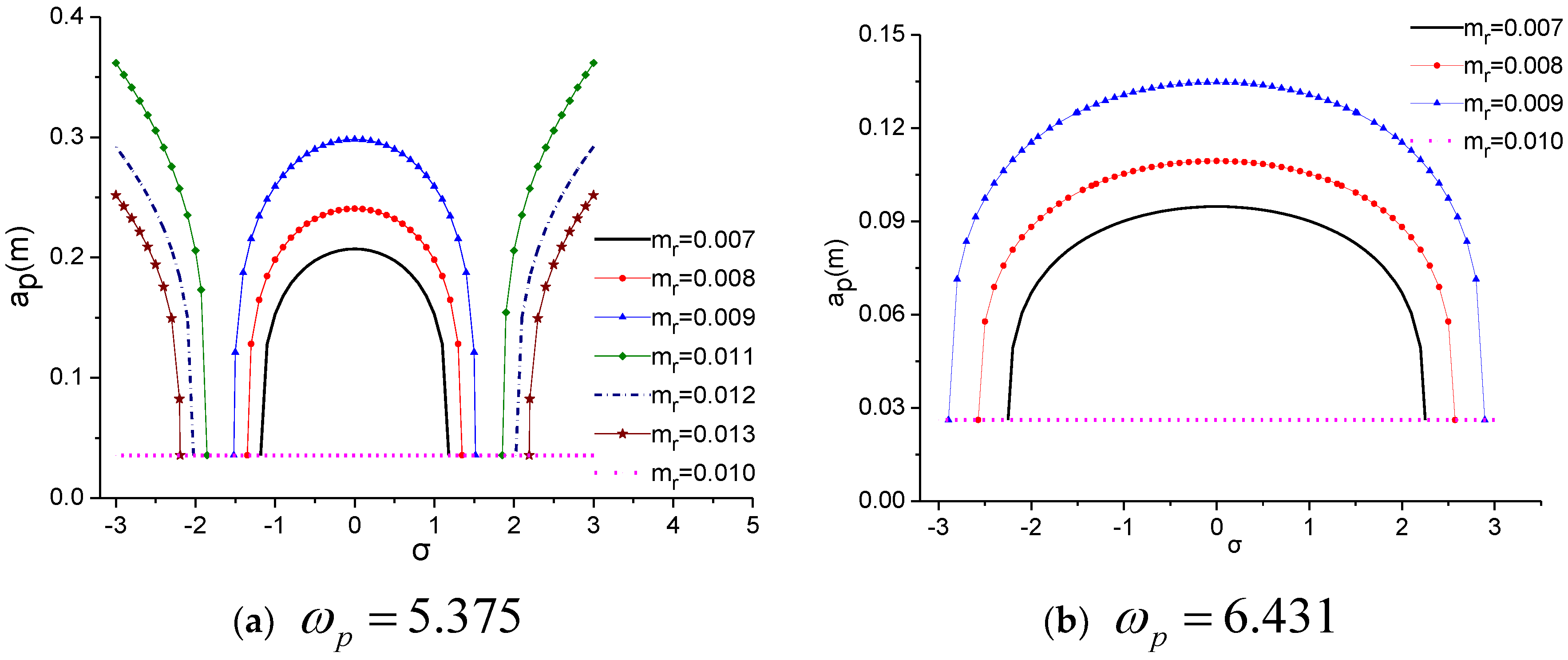
Figure 3, Figure 4 show that the lateral response amplitude frequency curves of pedestrians and footbridges will vary due to the different walking frequencies of pedestrians. In detail, assuming , with the same frequency tuning parameters, the larger the mass ratio is, the larger the pedestrian lateral response amplitude becomes. Moreover, the closer the pedestrians’ frequency is to the natural frequency of the footbridge, the larger the response amplitude. When , under the same frequency tuning parameters, the larger the mass ratio is, the smaller the response amplitude is. In the case of , its response amplitude is the smallest. In addition, the lateral response amplitude frequency curve of the footbridge tends to shift to the left side, which presents features of a soft spring. This is because the pedestrian-footbridge interaction is taken into consideration, which has altered the dynamic features of the pedestrian-footbridge coupling system.
6.2. Phase Frequency Curve
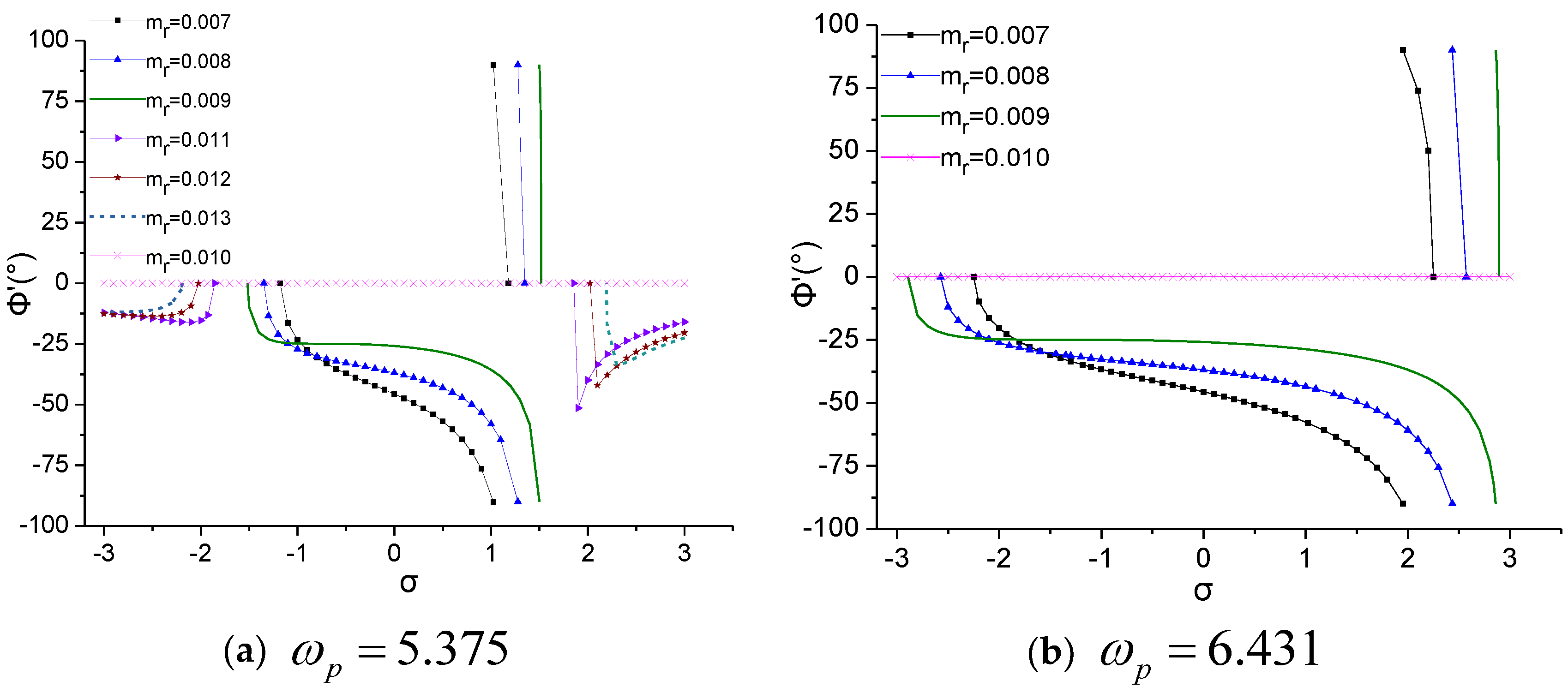
According to Figure 5, assuming that = 3.373, when the frequency modulation parameter is confined to the range of [1, 2.45], the Phase Angle between pedestrians’ absolute displacement and the footbridge displacement is positive, while the rest are negative; the variation range of the Phase Angle is limited to [−, ]. If < 0.01, the Phase Angle has two solutions: for > 0.01, the Phase Angle has three solutions; while for = 0.01, the phase is zero. Assuming = 6.431, the range of the frequency modulation parameter is limited to [1.7, 2.9], resulting in a positive Phase Angle of the pedestrians’ absolute displacement and footbridge displacement, while the rest are negative; the variation range of the Phase Angle is confined to [−, ]. If < 0.01, the Phase Angle has two solutions, while for = 0.01, the phase is zero.
Based on Figure 6, in the case where = 3.373 and the frequency modulation parameter is limited to the range of [1, 1.5], the Phase Angle of the interaction force and excitation speed is positive, while the rest are negative, and its variation range of the Phase Angle is confined to [−, ]. For ≠ 0.01, correspondingly, its Phase Angle has two solutions; for = 0.01, the phase is zero. However, it is assumed that = 6.431 and that the range of the frequency modulation parameter is limited to [1.7, 2.9]. The Phase Angle between the interaction force and excitation speed is positive, while the rest are negative, and its variation of the Phase Angle is confined to the range of [−, ]. For < 0.01, the Phase Angle has two solutions, while for = 0.01, the phase is zero.
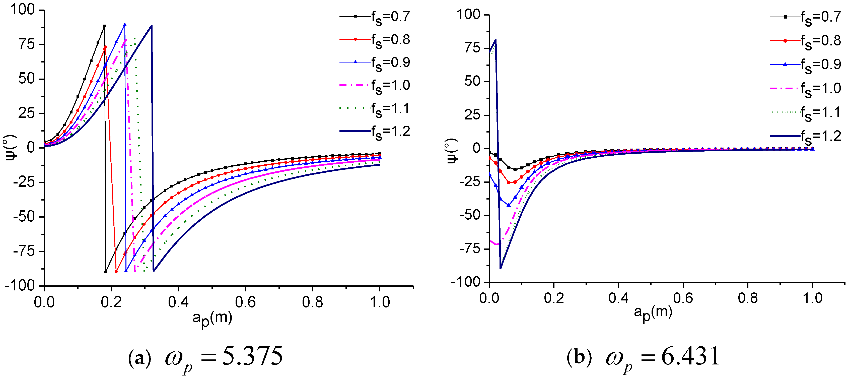
Taking Figure 7 into account, it is proven that, based on different pedestrian lateral walking frequencies, the Phase Angle between pedestrians’ lateral absolute displacement and the footbridge lateral vibration displacement varies according to the lateral relative displacement of pedestrians. The larger the natural frequency of the footbridge is, the larger the Phase Angle becomes. In addition, the Phase Angle tends to be 0 with an increasing pedestrian lateral amplitude, which indicates that the Phase Angle is a constant value in the case of a considerably large vibration amplitude.
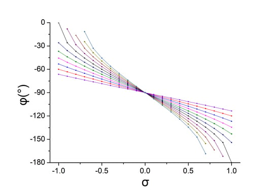
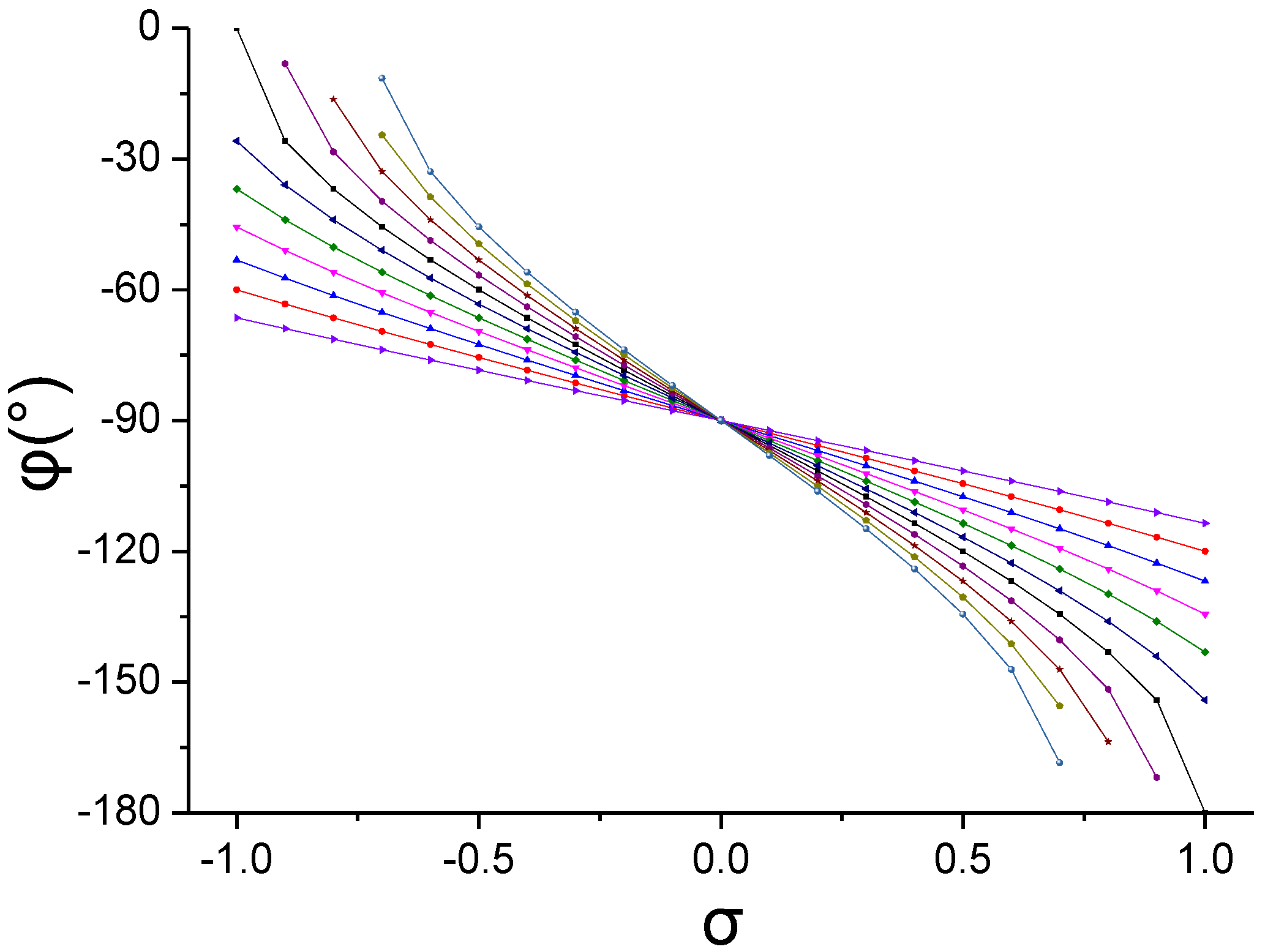
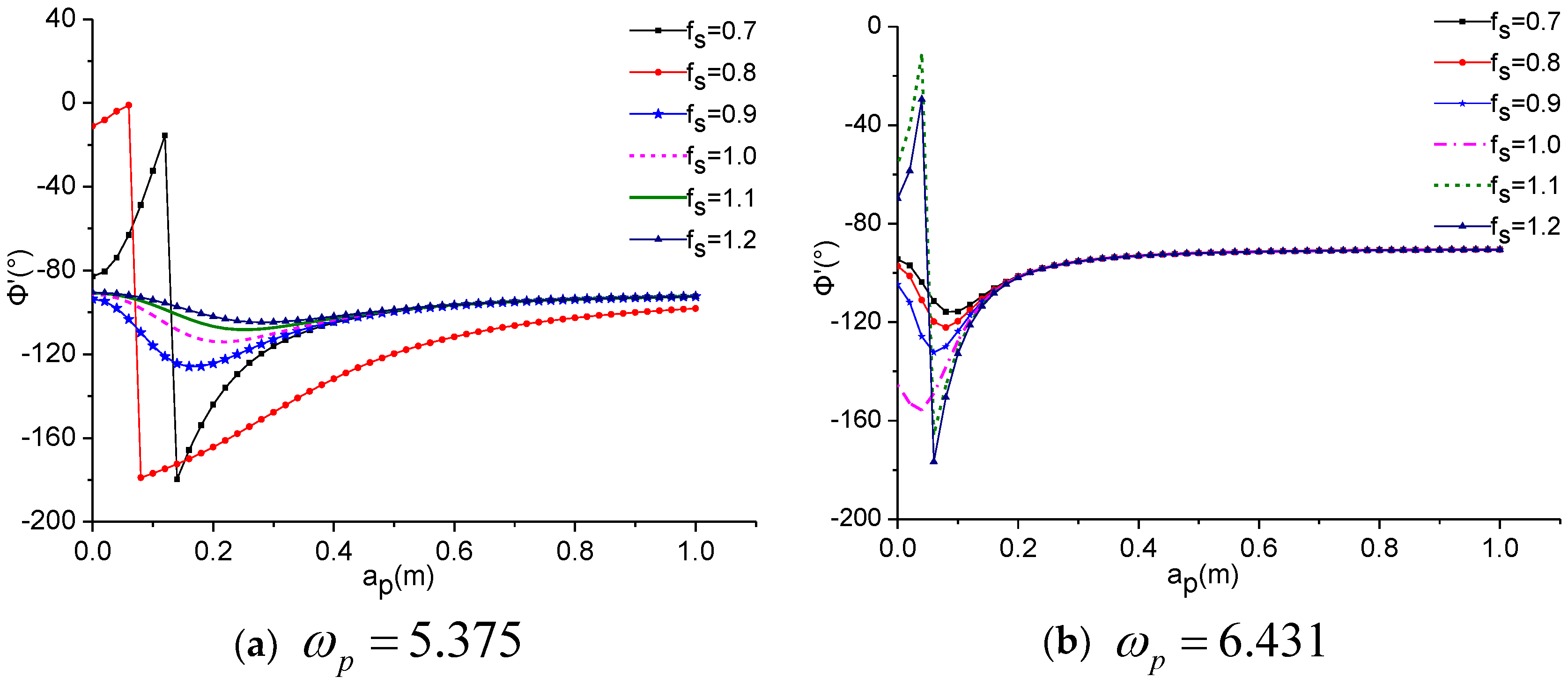
Figure 8 shows that, based on different pedestrian lateral walking frequencies, the Phase Angle between the interaction force and footbridge lateral vibration speed differs according to the lateral relative displacement of pedestrians. In addition, the Phase Angle tends to −90° as pedestrians’ lateral amplitude increases. For this reason, it is concluded that the Phase Angle is a constant value due to the considerable large vibration amplitude.
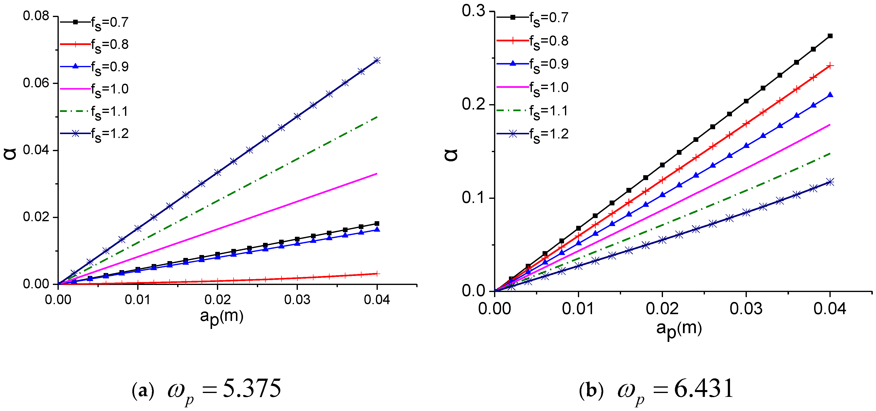
Considering Figure 9, the pedestrian-footbridge interaction dynamic load factor varies based on the lateral walking frequency of pedestrians. In fact, the dynamic load coefficient varies linearly with pedestrians’ lateral amplitude.
Figure 10 indicates that the pedestrian-footbridge interaction dynamic load factor becomes different as the pedestrian lateral walking frequency changes. To be more specific, the smaller the natural frequency of the footbridge is, the larger the is; conversely, the larger the natural frequency of the footbridge is, the smaller the is, and becomes larger due to the increasing lateral relative displacement of pedestrians.
7. Conclusions
This paper presents research on a pedestrians’ lateral force model of the hybrid Van der Pol/Rayleigh to model the interaction dynamic pedestrian-flexible footbridge lateral coupling system. In addition, the nonlinear dynamic response of the pedestrian-footbridge coupling system and the lateral interaction of pedestrians and flexible footbridges are investigated by adopting a multiscale method to decouple the equation.
(1) The lateral response amplitude frequency curves of pedestrians and footbridges vary for different pedestrian walking frequencies. If , under the same frequency tuning parameter, the larger the mass ratio is, the larger the pedestrian lateral response amplitude is. If , the larger the mass ratio is, the smaller the response amplitude. The response amplitude is the smallest in the case of . Moreover, the lateral response amplitude frequency curve of the footbridge tends to shift to the left side, which shows features of a soft spring. The pedestrian-footbridge interaction is taken into consideration because the dynamic features of the pedestrian-footbridge coupling system are shifted.
(2) The range of the Phase Angle is confined to [−, ] between pedestrians’ absolute displacement and the displacement of the footbridge, as well as between the interaction force and excitation speed.
(3) The Phase Angle between pedestrians’ lateral absolute displacement and the footbridge lateral vibration displacement varies according to the lateral relative displacement of pedestrians. The range of its variation is limited to [−, ]. The larger the natural frequency of the footbridge is, the larger the Phase Angle is. In addition, the Phase Angle approaches zero with an increasing pedestrian lateral amplitude. The Phase Angle between the interaction force and the footbridge lateral vibration speed changes according to the lateral relative displacement of pedestrians. Its variation range is (0, ). As the lateral amplitude of pedestrians increases, the Phase Angle tends to −.
(4) The dynamic load coefficient varies linearly in the case of different pedestrians’ lateral amplitudes. The smaller the natural frequency of the footbridge is, the larger the ratio of is. Furthermore, the larger the natural frequency of the footbridge is, the smaller the ratio of is. In addition, increases according to the increase in the lateral relative displacement of pedestrians.
Author Contributions
The work presented in this paper was conducted in collaboration with all the authors. Z.C.: Data curation, Formal analysis, Investigation, Methodology, Software, Visualization, Writing—original draft, Funding acquisition; S.C.: Data curation, Validation, Visualization. X.Y.: Funding acquisition, Methodology, Project administration, Validation, Writing—review & editing. Y.Z.: supervision.
Funding
The work described in this paper was financially supported by the National Natural Science Foundation of China (Grant No. 51608136), the Doctoral research start-up fund project of Foshan University (Grant No. gg040930), the Foshan self-funded science and technology plan project (Grant No. 1920001001539).
Acknowledgments
The authors would like to thank all participants who provide help support for our approach.
Conflicts of Interest
The authors declare no conflicts of interest.
References
- Shahabpoor, E.; Pavic, A.; Racic, V. Identification of mass-spring-damper model of walking humans. Structures 2016, 5, 233–246. [Google Scholar] [CrossRef] [Green Version]
- Lilin, C.; Dong, C.; Guojun, Y. Two Simplified Models for Human-Structure Vertical Interaction. J. Southwest Jiaotong Univ. 2018, 53, 1166–1172. [Google Scholar]
- Hao-xiang, H.; Wei-ming, Y.; Ai-lin, Z.; Zhuo, W. Human-structure dynamic interaction and comfort evaluation in vertical ambient vibration. J. Vib. Eng. 2008, 21, 446–451. [Google Scholar]
- Zhou, C.; Quansheng, Y.; Junliang, H.; Shi-ping, H.; Xiao-lin, Y. Coupling Vibration Investigation and Parameter Analysis of Crowd-Bridge System. J. South China Univ. Technol. (Nat. Sci. Ed.) 2014, 42, 75–83. [Google Scholar]
- Van Nimmen, K.; Lombaert, G.; De Roeck, G.; Van den Broeck, P. The impact of vertical human-structure interaction on the response of footbridges to pedestrian excitation. J. Sound Vib. 2017, 402, 104–121. [Google Scholar] [CrossRef] [Green Version]
- Mulas, M.G.; Lai, E.; Lastrico, G. Coupled analysis of footbridge-pedestrian dynamic interaction. Eng. Struct. 2018, 176, 127–142. [Google Scholar] [CrossRef]
- Li, Q.; Fan, J.; Nie, J.; Li, Q.; Chen, Y. Crowd-induced random vibration of footbridge and vibration control using multiple tuned mass dampers. J. Sound. Vib. 2010, 329, 4068–4092. [Google Scholar] [CrossRef]
- Tubino, F. Probabilistic assessment of the dynamic interaction between multiple pedestrians and. vertical vibrations of footbridges. J. Sound. Vib. 2018, 417, 80–96. [Google Scholar] [CrossRef]
- Shoutao, L.; Min, R.; Zhifeng, Z.; Meiling, X. Theoretical models of a vertical human-structure interaction system. J. Vib. Shock 2019, 38, 174–179. [Google Scholar]
- Toso, M.A.; Gomes, H.M. A coupled biodynamic model for crowd-footbridge interaction. Eng. Struct. 2018, 177, 47–60. [Google Scholar] [CrossRef]
- Zhang, M.; Georgakis, C.T.; Chen, J. Biomechanically excited SMD model of a walking pedestrian. J. Bridge Eng. 2016, 21, C4016003. [Google Scholar] [CrossRef]
- Hamill, J.; Knutzen, K.M. Biomechanical Basis of Human Movement, 3rd ed.; Lippincott Williams & Wilkins: Philadelphia, PA, USA, 2012. [Google Scholar]
- De-yuan, D.; Guo-rui, C.; Zhou, C.; Xiao-qin, Z.; Jian-xin, L. Study on nonlinear paramettic vibration of footbridge considering time-lag effect. IOP Conf. Ser. Mater. Sci. Eng. 2019, 490, 89–96. [Google Scholar]
- Belykh, I.; Jeter, R.; Belykh, V. Foot force models of crowd dynamics on a wobbly bridge. Sci. Adv. 2017, 3, 1–12. [Google Scholar] [CrossRef] [PubMed] [Green Version]
- Macdonald, J.H.G. Pedestrian-induced vibrations of the Clifton Suspension Bridge. Proc. Inst. Civ. Eng. Bridge Eng. 2008, 161, 69–77. [Google Scholar] [CrossRef]
- Carrol, S.P.; Owen, J.S.; Hussein, M.F.M. A coupled biomechanical/discrete element crowd model of crowd-bridge dynamic interaction and application to the Clifton Suspension Bridge. Eng. Struct. 2013, 49, 58–75. [Google Scholar] [CrossRef]
- Bocian, M.; Macdonald, J.H.G.; Burn, J.F. Probabilistic criteria for lateral dynamic stability of bridges under crowd loading. Comput. Struct. 2014, 136, 108–119. [Google Scholar] [CrossRef]
- Newland, D.E. Pedestrian excitation of footbridge. J. Bridge Eng. ASCE 2005, 10, 107–112. [Google Scholar]
- Erlicher, S.; Trovato, A.; Argoul, P. A modified hybrid Van der Pol/Rayleigh model for the lateral pedestrian force on a periodically moving floor. Mech. Syst. Signal Process. 2013, 41, 485–501. [Google Scholar] [CrossRef]
- Kumar, P.; Kumar, A.; Erlicher, S. A modified hybrid Van der Pol-Duffing-Rayleigh oscillator for modelling the lateral walking force on a rigid floor. Phys. D Nonlinear Phenomena. 2017, 358, 1–14. [Google Scholar] [CrossRef]
- Abrams, D.M. Two coupled oscillator models: The millennium bridge and the chimera state. Ph.D. Thesis, Cornell University, Ithaca, NY, USA, 2006. [Google Scholar]
- Zhou, C. A Study on Non-linear Dynamic Interaction between Long-span Flexible Footbridge and Pedestrians. Ph.D. Thesis, South China University of Technology, Guangzhou, China, 2015. [Google Scholar]
Figure 1.
Lateral coupling of an individual pedestrian and a footbridge.

Figure 2.
Effect of frequency tuning parameters on the Phase Angle between pedestrians and footbridges under different amplitude ratios.
Figure 2.
Effect of frequency tuning parameters on the Phase Angle between pedestrians and footbridges under different amplitude ratios.

Figure 3.
Amplitude frequency curve of pedestrians’ lateral vibration.

Figure 4.
Amplitude frequency curve of lateral vibration of the footbridge.

Figure 5.
Phase frequency curve between pedestrians’ absolute displacement and footbridge displacement.
Figure 5.
Phase frequency curve between pedestrians’ absolute displacement and footbridge displacement.

Figure 6.
Phase Angle between interaction force and excitation speed.

Figure 7.
Variation of the Phase Angle between pedestrians’ lateral absolute displacement and footbridge lateral vibration displacement according to the lateral relative displacement of pedestrians.
Figure 7.
Variation of the Phase Angle between pedestrians’ lateral absolute displacement and footbridge lateral vibration displacement according to the lateral relative displacement of pedestrians.

Figure 8.
Variation of the Phase Angle between the interaction force and footbridge lateral vibration speed according to the lateral relative displacement of pedestrians.
Figure 8.
Variation of the Phase Angle between the interaction force and footbridge lateral vibration speed according to the lateral relative displacement of pedestrians.

Figure 9.
Variation of pedestrian-footbridge interaction dynamic load factor according to pedestrians’ lateral relative displacement.
Figure 9.
Variation of pedestrian-footbridge interaction dynamic load factor according to pedestrians’ lateral relative displacement.

Figure 10.
The impact of pedestrians’ lateral relative displacement on the ratio of pedestrians’ lateral absolute displacement to pedestrians’ lateral relative displacement.
Figure 10.
The impact of pedestrians’ lateral relative displacement on the ratio of pedestrians’ lateral absolute displacement to pedestrians’ lateral relative displacement.

© 2019 by the authors. Licensee MDPI, Basel, Switzerland. This article is an open access article distributed under the terms and conditions of the Creative Commons Attribution (CC BY) license (http://creativecommons.org/licenses/by/4.0/).
Share and Cite
MDPI and ACS Style
Chen, Z.; Chen, S.; Ye, X.; Zhou, Y. A Study on a Mechanism of Lateral Pedestrian-Footbridge Interaction. Appl. Sci. 2019, 9, 5257. https://0-doi-org.brum.beds.ac.uk/10.3390/app9235257
AMA Style
Chen Z, Chen S, Ye X, Zhou Y. A Study on a Mechanism of Lateral Pedestrian-Footbridge Interaction. Applied Sciences. 2019; 9(23):5257. https://0-doi-org.brum.beds.ac.uk/10.3390/app9235257
Chicago/Turabian StyleChen, Zhou, Siyuan Chen, Xijun Ye, and Yunlai Zhou. 2019. "A Study on a Mechanism of Lateral Pedestrian-Footbridge Interaction" Applied Sciences 9, no. 23: 5257. https://0-doi-org.brum.beds.ac.uk/10.3390/app9235257
Note that from the first issue of 2016, this journal uses article numbers instead of page numbers. See further details here.