Research and Development of a Novel TIG Welding Torch for Joining Thin Sheets


1
Science-Technology and International Cooperation Department, Sao do University, Hai Duong 170000, Vietnam
2
Research and Development Department, Murata Welding Laboratories Co., Ltd., Osaka 5320012, Japan
3
Welding Department, Hanoi University of Science and Technology, Hanoi 100000, Vietnam
4
Faculty of Mechanical Engineering-Mechatronics, Phenikaa University, Hanoi 100000, Vietnam
5
Engineering Research Center of Advanced Manufacturing Technology for Automotive Components, Beijing University of Technology, Beijing 100124, China
*
Author to whom correspondence should be addressed.
†
Authors contributed equally to this work, they are considered as co-first author.
Appl. Sci. 2019, 9(23), 5260; https://0-doi-org.brum.beds.ac.uk/10.3390/app9235260
Submission received: 22 October 2019
/
Revised: 28 November 2019
/
Accepted: 29 November 2019
/
Published: 3 December 2019
(This article belongs to the Section Mechanical Engineering)
Abstract
:Featured Application
We are developing a novel TIG torch for joining thin sheets efficiently. Using this torch: (1) the arc plasma stabilization is increased and (2) the heat input on the base metal is reduced. As a result, it is suitable to weld thin sheets with high welding speed and low welding current.
Abstract
This paper aims to develop a novel tungsten inner gas (TIG) welding torch in order to join thin sheets efficiently. Using a narrowing nozzle (constricted nozzle) inside a conventional TIG torch can critically improve the position accuracy of the tungsten electrode and also the arc plasma characteristics and heat input density. In order to evaluate the efficiency of this new torch, weld bead appearance and cross-section images were examined by an optical microscope, scanning electron microscope (SEM), and electron back scatter diffraction patterns (EBSD). The results showed that in all cases, the weld bead profile was stable without undercut and burn-through. Full penetration weld was seen. The width of weld bead on the bottom surface was increased much in comparison to conventional TIG welding. However, the results from SEM and EBSD images indicated that in the case of low welding current, the blowholes were found out on the side of the thinner material (SS400). The penetration of SUS430 material to SS400 material was not good. It seems that no fusion of SUS430 material to SS400 at the bottom surface can be seen. Meanwhile, no blowholes were seen in the case of high welding current. The penetration was better, and the fusion was reached on the bottom surface.
1. Introduction
Generally, welding in the plat position is the easiest way to keep the arc stable, preventing a drop of molten metal before solidification. However, in automatically production lines, welding in this position is not always applied. Sometimes, joints are required in the vertical position. On the other hand, for in welding in the vertical position, due to the critical influence of gravity force and the difficult set-up experimental process, no reports were found in the case of thin sheets. Only a few papers were published recently for joining thin plates by a micro-tungsten inner gas (TIG) welding process [1], micro-Plasma welding [2,3], and laser welding [4] in the plat position. For the laser welding process, because of the complexity in set-up, high cost and restricted safety conditions, it is difficult to apply in factories rather than laboratories and universities. For the micro-TIG welding process, since the tungsten electrode can be freely moved inside the nozzle, its position in comparison to the target weld position is difficult to adjust. Furthermore, arc plasma is too freely oscillated without orientation. This leads to the instability especially in the case of welding thin sheets (high welding speed and low current). In addition, micro-TIG and micro-Plasma welding equipment is normally small and flexible with the torch in semi-automatic status. In order to integrate automatically production lines, a hand-arm for keeping and controlling the welding torch needs to be specially developed. This can cause an increase in cost. As a result, these conventional welding methods have low efficiency in automatically production lines of thin sheets, especially in vertical welding position.
In vertical welding, the melting material of the weld pool is tended in the downward direction according to gravity force direction. Therefore, the heat input is increased, resulting in a large and long weld pool. In this case, the molten metal of the weld pool is easy to drop. So, adjustment of welding parameters is strictly requested to prevent this phenomenon [5]. On the other hand, the stainless steel is easily distorted by the thermal process, especially in welding thin plates [6,7]. As a result, welding thin plates of stainless steel in the vertical welding position is easy to cause overheating, resulting in welding defects such as burn-through. In order to prevent burn-through, it is necessary to control the penetration through welding parameters such as: reducing the welding current, increasing the welding speed, etc. [8]. However, decreasing the welding current or increasing the welding speed, it may result in other defects such as a blowhole, lack of fusion, under cut, or incomplete penetration due to insufficient heat input.
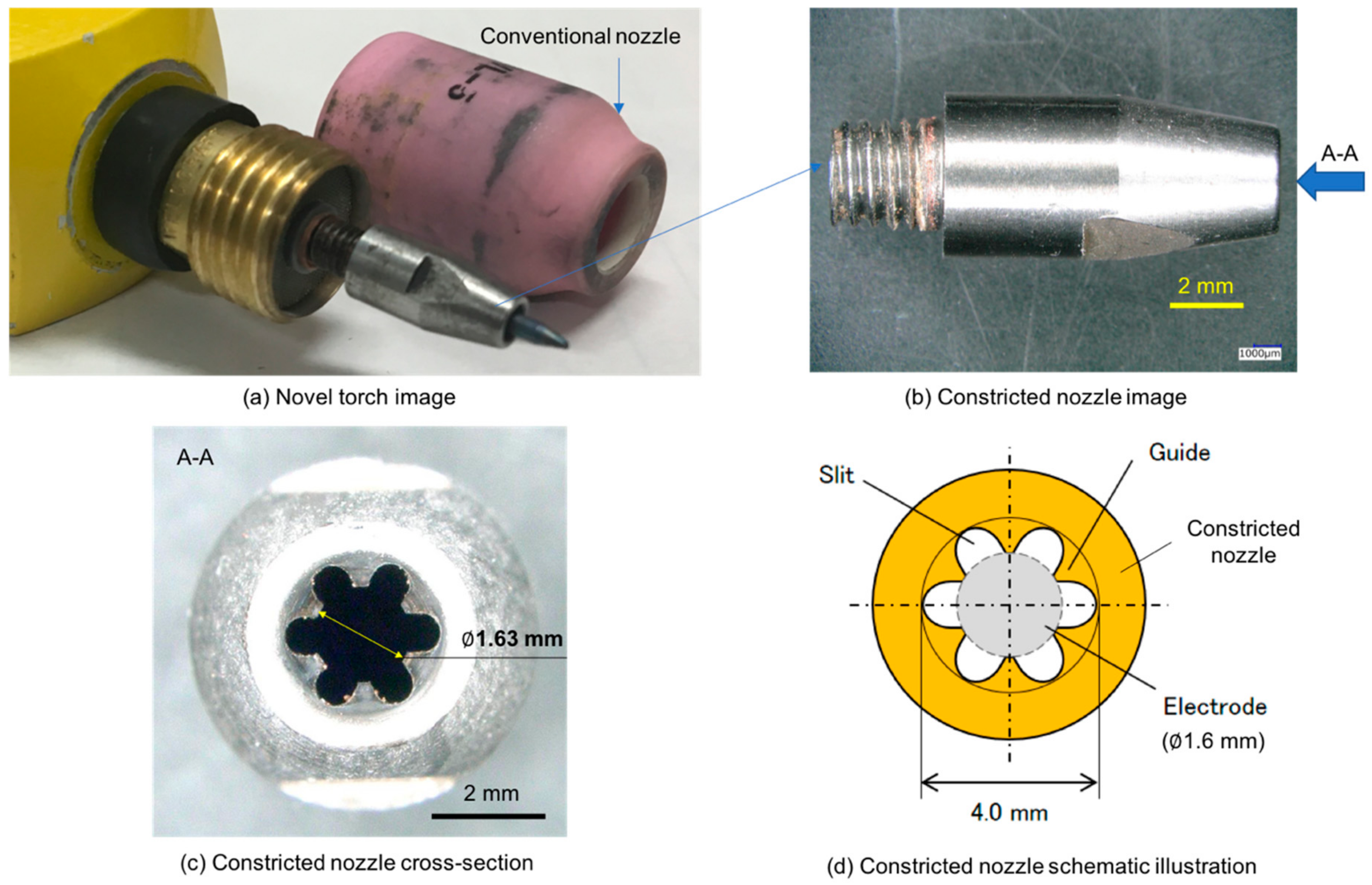
In order to solve these problems, in recent years, an automatic TIG welding device using a novel TIG torch has been developed for joining thin plates [9,10]. This novel torch has two nozzles. One of them has a small diameter covering the surrounding zone of the tungsten electrode. This nozzle is called the constricted nozzle. A real image and schematic of this nozzle is shown in Figure 1. As shown in this image, the constricted nozzle was with six small slits and six guides. The distance between the two guides was about 1.63–1.65 mm. This nozzle was long and extend outside conventional nozzle. Furthermore, the tungsten electrode diameter was 1.6 mm. As a result, it is impossible for the tungsten electrode to move freely inside the torch. A small amount of shielding gas from the torch flows between the tungsten electrode and this nozzle with a very high speed. This nozzle is called the “constricted nozzle” and this shielding gas is called the inner gas. Another kind of nozzle has a similar diameter to the nozzle of a conventional TIG welding torch (conventional nozzle). This nozzle has a large diameter to orient the shielding gas flow away from the electrode. This nozzle is called the outer nozzle and the shielding gas was controlled by this nozzle as the outer gas. Among the shielding gases, the outer gas has a task similar to the shielding gas flow in the case of the conventional TIG welding process.
In this case, the inner gas flow plays a main role in pressing the arc plasma, resulting in a more rigidified arc plasma in comparison to the conventional TIG welding process. Its gas flow rate was increased strongly because it is throughout a small gap between the tungsten electrode and the constricted nozzle. Using this nozzle, the plasma arc characteristics can be improved and the heat input can be precisely controlled to maintain the welding stability. In this case, the arc column is constricted through the thermal pinch effect to increase the temperature at the center area of the arc plasma [11]. Therefore, it leads a concentrated plasma flow with a high-speed plasma jet and high arc pressure impinging on the base metal surface. In addition, it accelerated the plasma jet through a high-speed inner gas flow, as mentioned above. Therefore, (1) the magnetic field acting on the arc; (2) the energy density of the arc plasma; and (3) the discharge capacity of electrons are increased strongly in comparison to the TIG welding process using a conventional TIG torch [12]. Another advantage of this gas flow is that it increases the cooling rate and decreases the temperature of the tungsten electrode, therefore the life cycle of the tungsten electrode can be extended and the stabilization of arc plasma can be kept during a long time. As a result, double shielding gas flows, thereby preventing the reduction of the shielding effect, which has been a problem in the conventional TIG welding process. In addition, due to the high-speed inner gas flow, the metal evaporation from the weld pool is pushed outside to prevent the attachment of evaporated metal on the tip of the tungsten electrode. Consequently, the tungsten electrode become cleaner, reducing contamination, and the arc length can be set up in extremely short distances. This is a useful characteristic in order to prevent the expansion of the arc plasma, which is an advantaged point that the conventional TIG welding process does not have. From all of the above, welding with high speed and low current can be obtained. Consequently, in comparison to the TIG welding process using a conventional TIG torch better welding quality can be obtained at a high speed and a low current for joining thin sheets.
As a result, many factories worldwide have efficiently utilized our equipment. In order to clarify the advantages of this torch, our group has been starting to study the mechanism and examine the availability of this welding technology.
In a paper by Konishi et al., the influence of the constricted nozzle was discussed using numerical simulation in the case of 3 mm arc length [13] with an anode of water-cooled copper. The results showed that, in comparison to the conventional TIG welding process, the heat flux on the anode surface was increased. Especially at the center of the arc, the heat flux was highly increased. However, the simulation is limited by boundary conditions and assumptions. Therefore, it is difficult to obtain comprehensive and full understanding about the mechanism of this process with only a numerical method. Therefore, the experiments are also indispensable. In a recent paper, Miki et al. discussed the influence of oxygen contamination and heat input on the anode surface in order to ensure a high-quality welding [14] in the case of an anode of a water-cooled copper. The experimental results evidenced that in the case of TIG welding with a constricted nozzle, the oxygen content on the weld pool surface is lower in comparison to the conventional TIG welding process. In another paper, Anh et al. performed experiments in practical welding conditions at industrial factories. This paper indicated that thin sheets of 0.1 mm can be welded with sound quality at an extremely short distance of arc length (0.1 mm), high welding speed and low welding current with no surface defects such as undercut and burn-through [15].
As a next step, this paper is addressed to examine the efficiency of this torch in welding thin sheets on an automatically production line with thin sheets of 0.2 mm and 0.4 mm. For evaluation of the welding results: (1) weld bead appearance was observed by an optical microscope and (2) welding samples were prepared and captured by scanning electron microscope (SEM) and electron back scatter diffraction patterns (EBSD).
2. Experimental Method
2.1. Welding Condition
In this experiment, two kinds of butt-joints were created including: (1) the butt-joint of two of the same material and (2) the butt-joint of dissimilar materials and different thicknesses. The materials are SS400 (Abel Company, Osaka, Japan) with a thickness of 0.2 mm and SUS430 (Abel company, Osaka, Japan) with thicknesses of 0.2 mm and 0.4 mm. Table 1 shows the welding conditions and chemical composition of base materials. A tungsten electrode (Murata Welding Laboratories Co., Ltd, Osaka, Japan) with a diameter of 1.6 mm was utilized. The tip angle was fixed at 30 degrees. The distance between tungsten electrode tips and the workpiece surface (arc length) was set up at 0.3 mm. Welding speed was 50 mms−1. The inner gas, outer shielding gas and back shielding gas were Ar + 30% He. The flow rate of inner gas was 2.5 Lmin−1. The flow rate of outer gas was 5.0 Lmin−1. For protecting the backside of the weldment, the back shielding gas with a flow rate of about 2.5 Lmin−1 was selected. The welding current was varied at three levels: 22 A, 55 A, and 65 A. No filler metal was applied in all experiments. The welding torch was set up identical with the contact surface of the two base metals. A series of four kinds of experimental conditions was performed, as shown in Table 1. Table 2 indicates the chemical compositions of base metals SS400 and SUS430. As can be seen in this table, the proportions of C element, Mn element, and Si element were less than 0.12%, 0.95%, and 0.30%, respectively in the case of SS400, and they were less than 0.10%, 1.0%, and 0.7%, respectively in the case of SUS430. Cr element was about 16–18% in SUS430.
2.2. Experimental Equipment
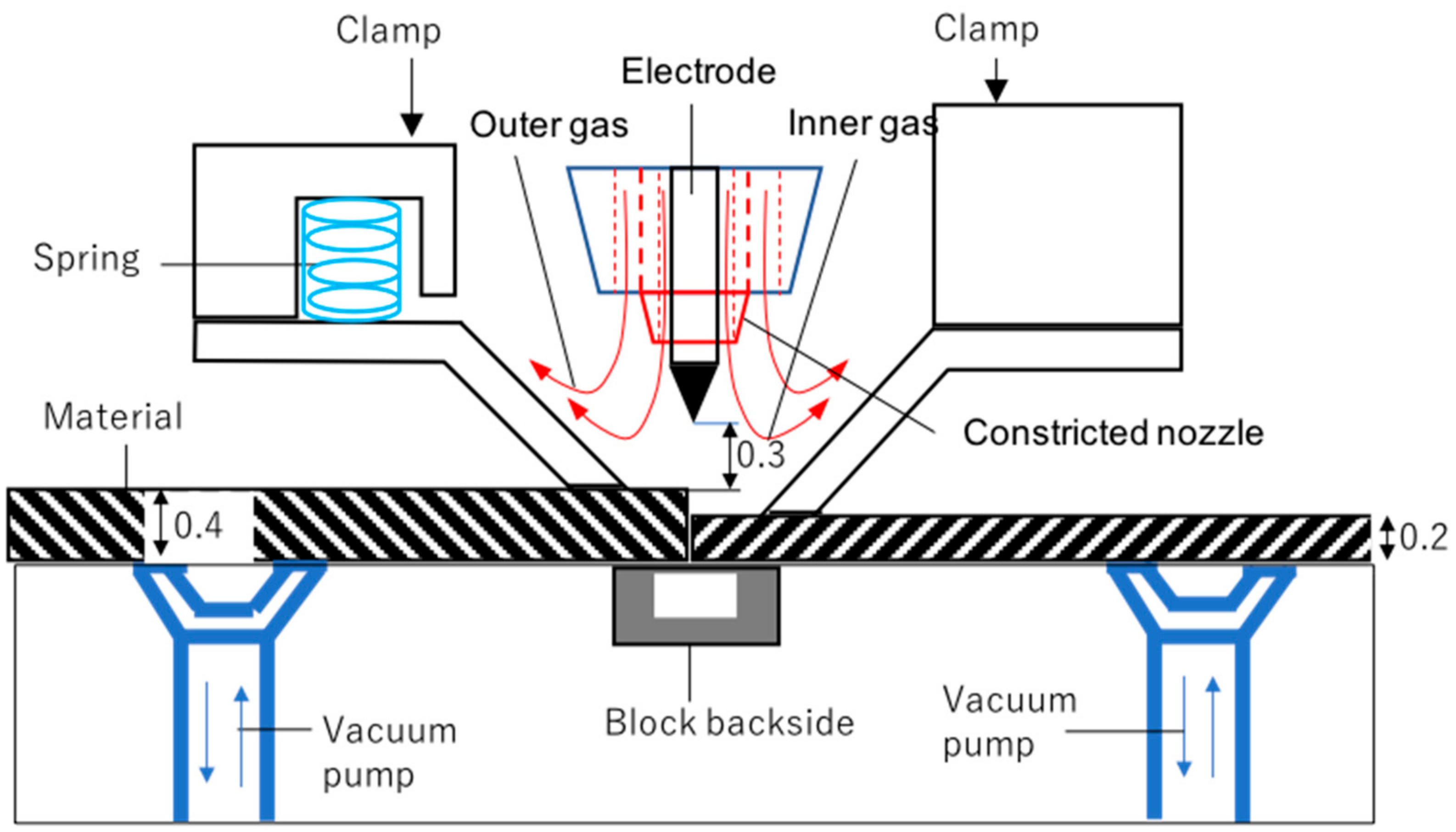
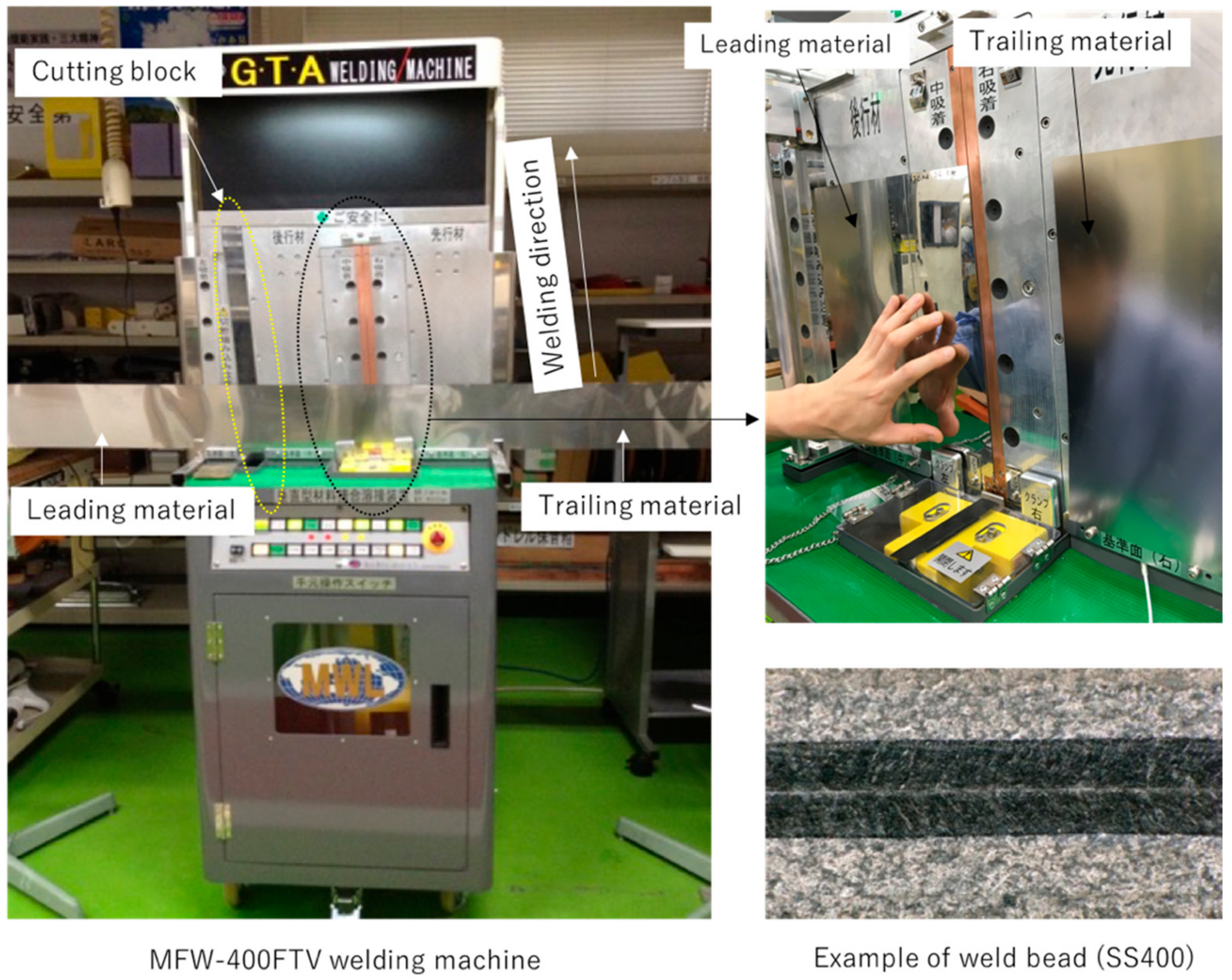
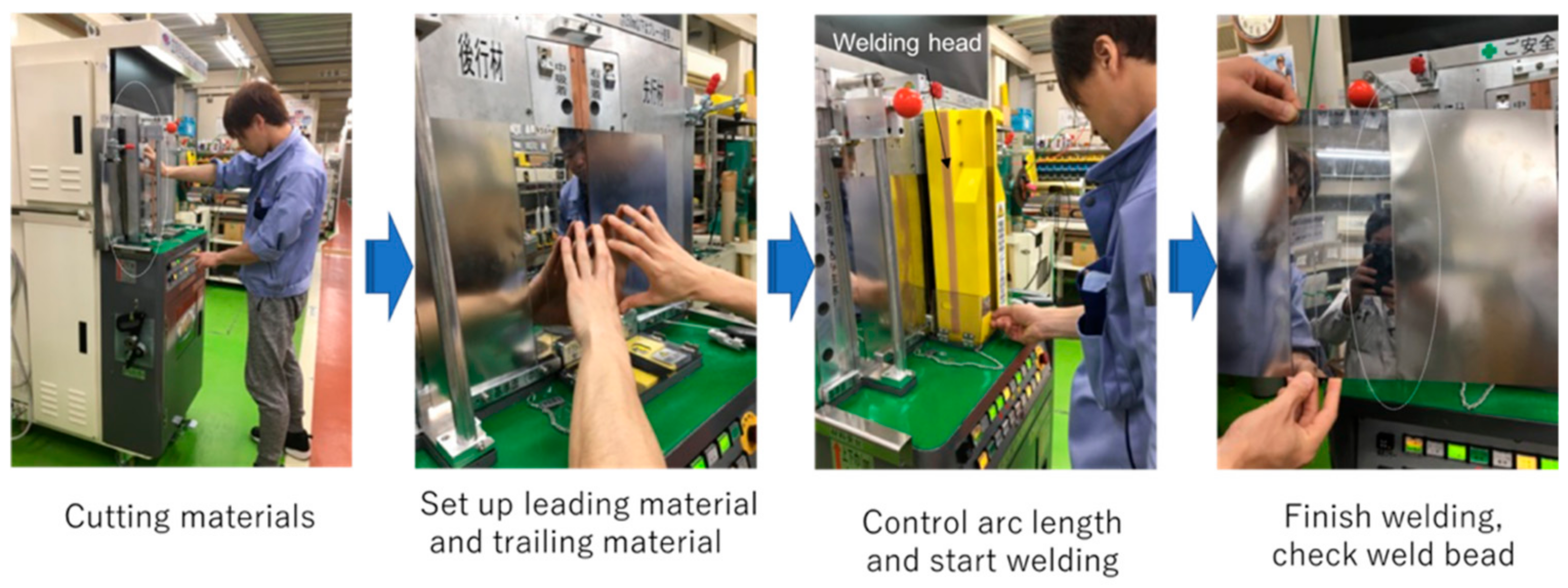
A schematic illustration of the experimental set-up is shown in Figure 2. A practical image of the equipment is shown in Figure 3. An automatic welding equipment for this experiment including a welding power source MFW-400FTV (Murata Welding Laboratories Co., Ltd., Osaka, Japan) was applied. The base metal was in two parts. One of them is the leading material, and the another one is the trailing material. The experimental process is indicated in Figure 4. This experimental process can be explained as follows: Firstly, the leading material and trailing material are cut by a cutting block. Next, the leading material is fixed by a clamp and a vacuum pump. After that, the trailing material is adjusted to be in contact with the leading material, and then it is fixed by a clamp and a vacuum pump too. Next, the arc length is adjusted to 0.3 mm and then the welding process is started. After finishing the welding process, the weld bead is checked before entering in the forming press line for the next task. As mentioned above, correctly controlling the heat input is a key factor for welding thin sheets. In our technology, the heat input is controlled by not only by the constricted nozzle but also by the width of the clamp and block backside. Details of the clamp and block backside can be seen in [15]. For checking welding defects, welding samples were cut, mounted, grinded, polished, and cleaned. Finally, EBSD images (TSL RBSD system, EDAX, Japan) and SEM images (VHX-D500, Keyence, Japan) were taken.
3. Experimental Results
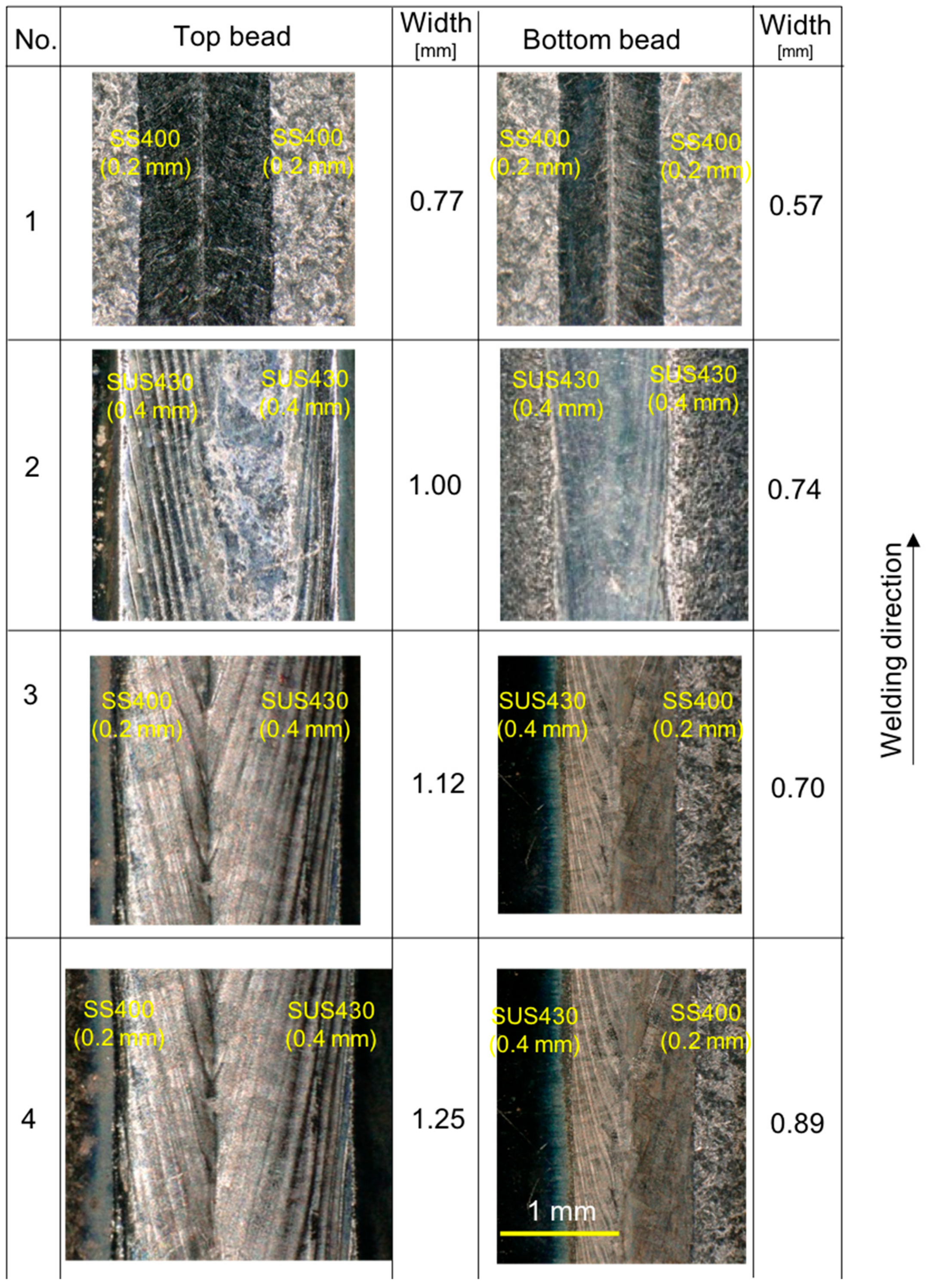
Figure 5 indicates the weld bead appearance in all cases. It can be seen that the weld pool seems be extended in the downward direction due to the opposition of gravity force to the welding direction. As a result, the weld pool boundary looks like a continuous semi- elliptic in the downward direction. It was also observed that no undercut or burn-through were seen in all welding conditions from No.1 to No.4. Moreover, the width of the weld bead was stable from starting welding until ending welding in all cases.
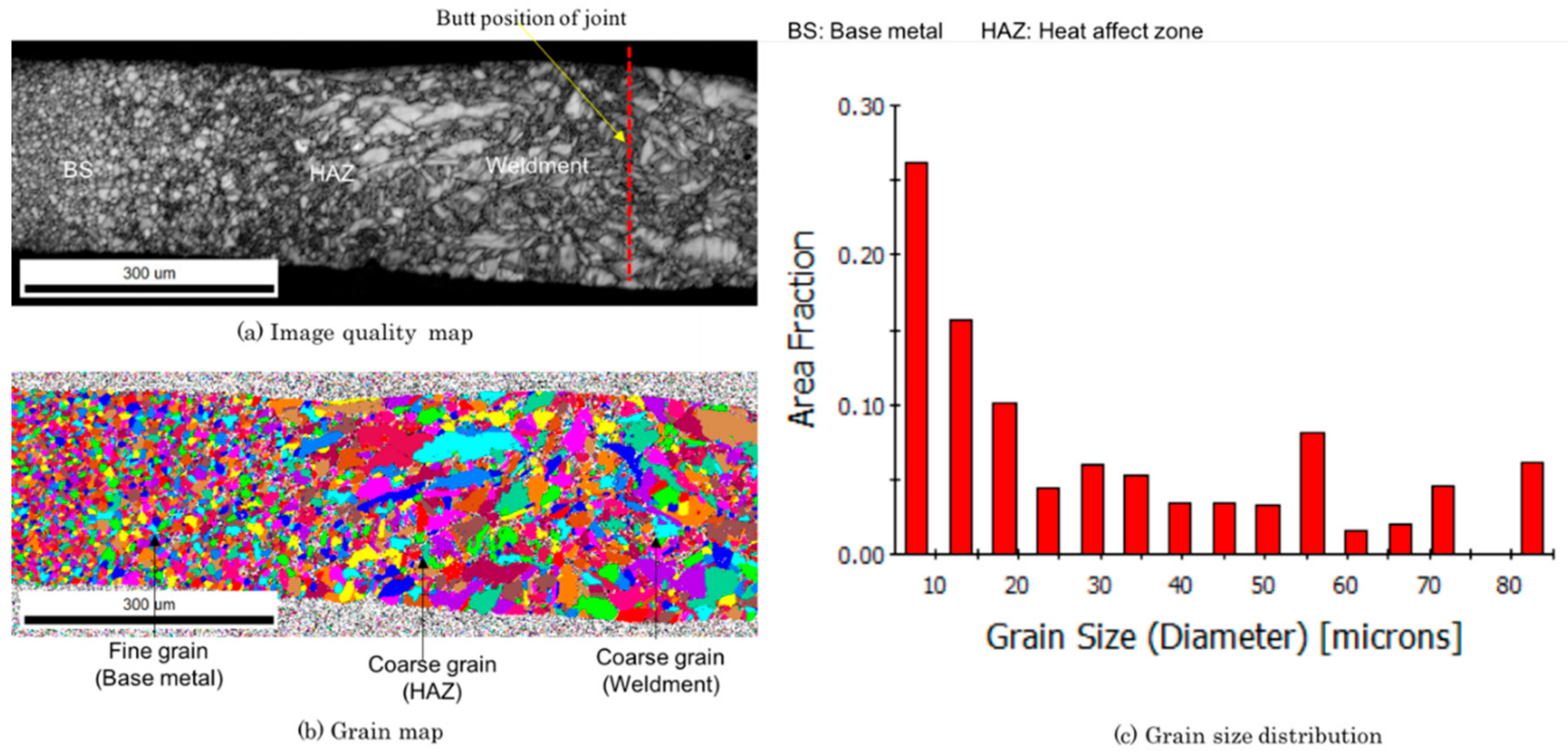
Figure 6 presents the EBSD analysis results in the weld zone for the No.1 case. Here, Figure 6a is an image quality (IQ) map. Figure 6b is a grain map (GM). Figure 6c shows grain size distribution (GSD). The red dotted line in Figure 6a indicates the butt position of the joint. In this case, no welding defects, such as circular black shadows were observed. It seems that there was a small change in grain size distribution from the base metal toward the weldment. Fine grains were seen on the base metal side. In the heat affected zone (HAZ), coarse grains can be seen. The grain size is distributed within 5–80 microns, and the average size is about 30 microns.
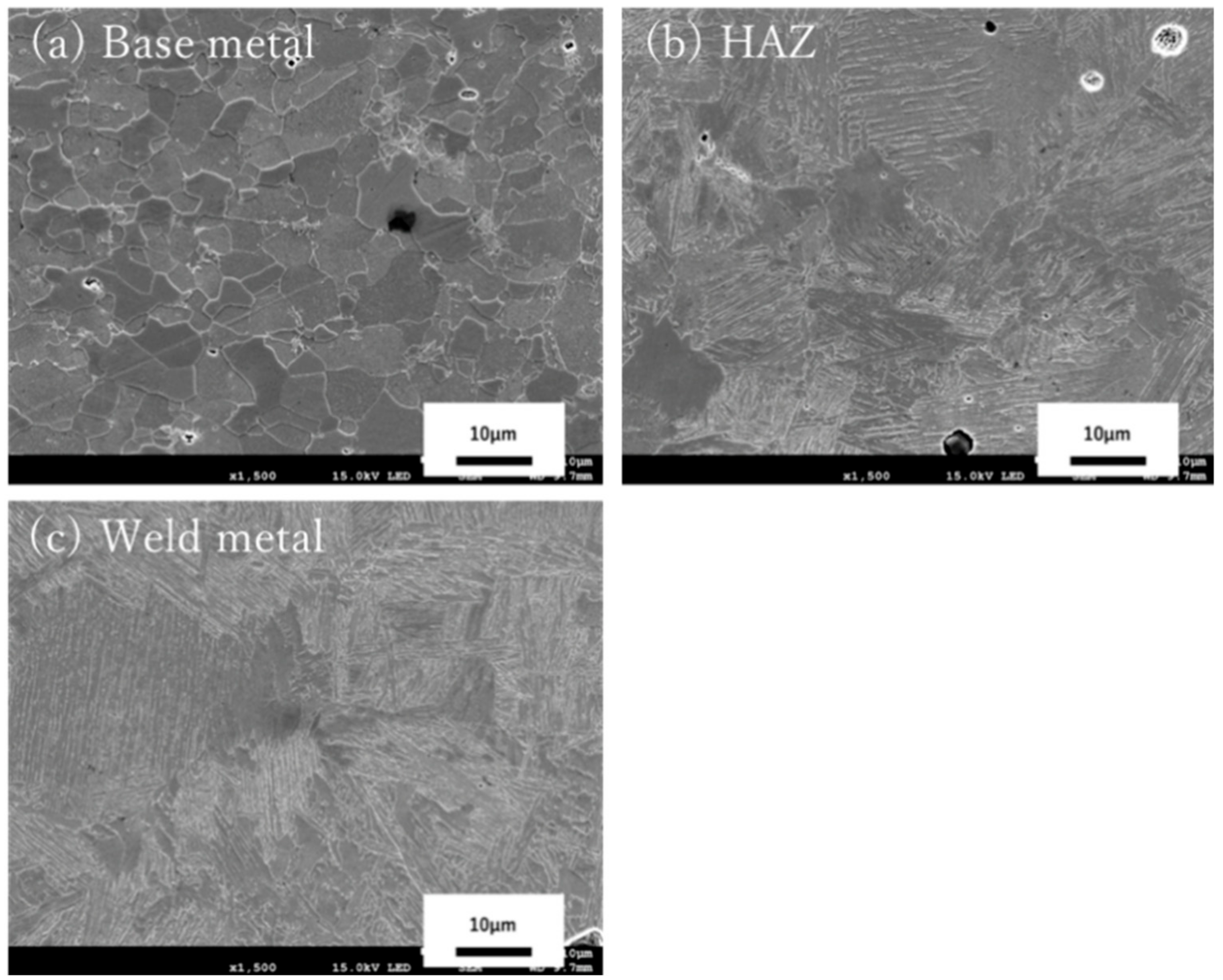
Figure 7 indicates the SEM observation results of the No.1 case. Figure 7a is the base metal. Figure 7b is the HAZ image. Figure 7c is the fusion zone. It can be seen that there are no circular black shadows in welding between SS400 materials with this welding condition.
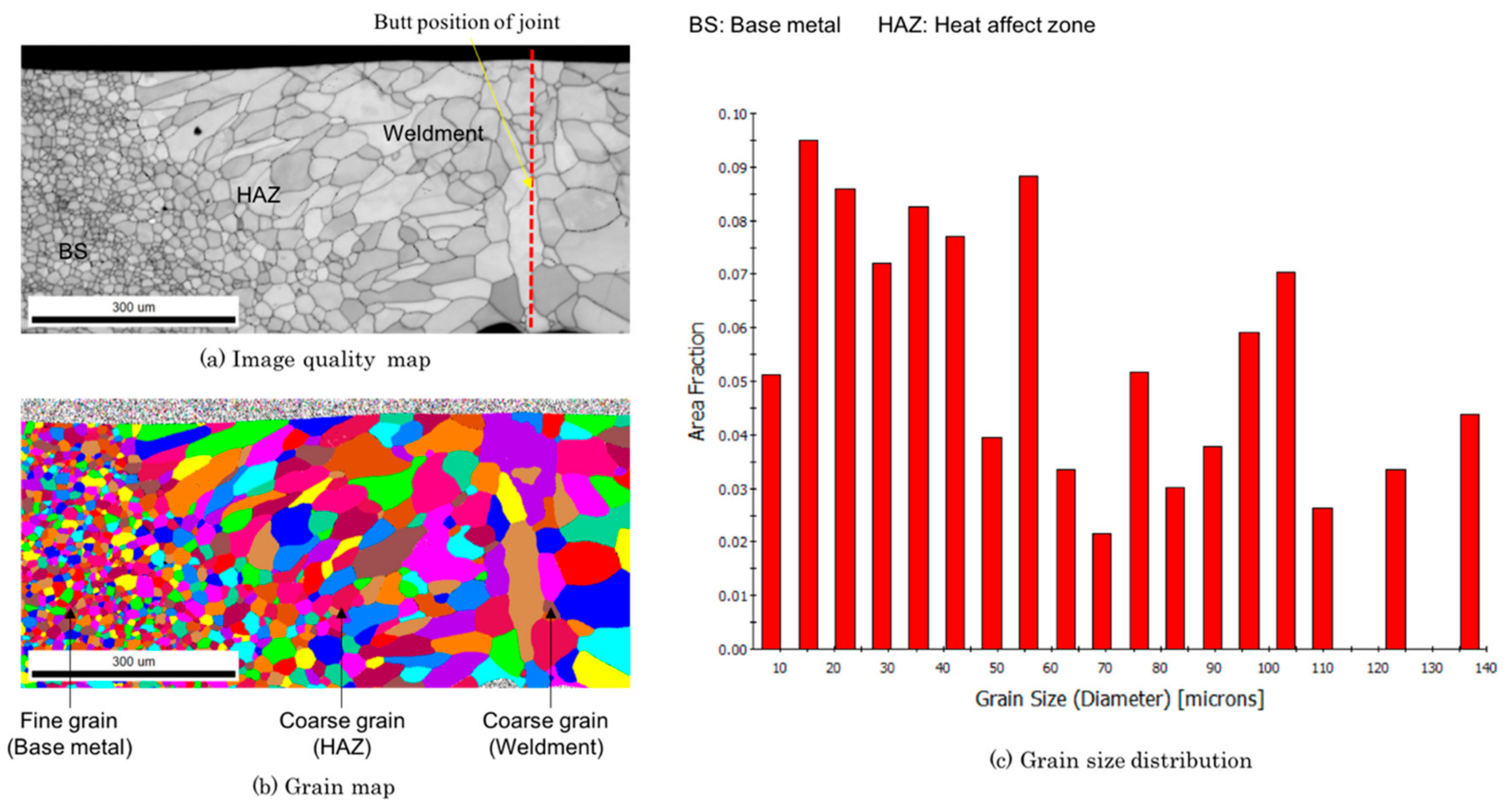
Figure 8 presents the EBSD analysis results in the weld zone of the No.2 case. Figure 8a is the IQ map. Figure 8b is the GM image. Figure 8c is the GSD image. The red dotted line in Figure 8a indicates the butt position of the joint. It seems that no circular black shadows were observed at both the weldment and HAZ in this welding condition. However, because SUS430 is a ferritic stainless steel, the grains size distribution is largely changed from the base metal toward the weldment. The grains were fine at the base metal. The grains coarsened at the weldment and HAZ. A large grain distribution within 50–140 microns can be seen.
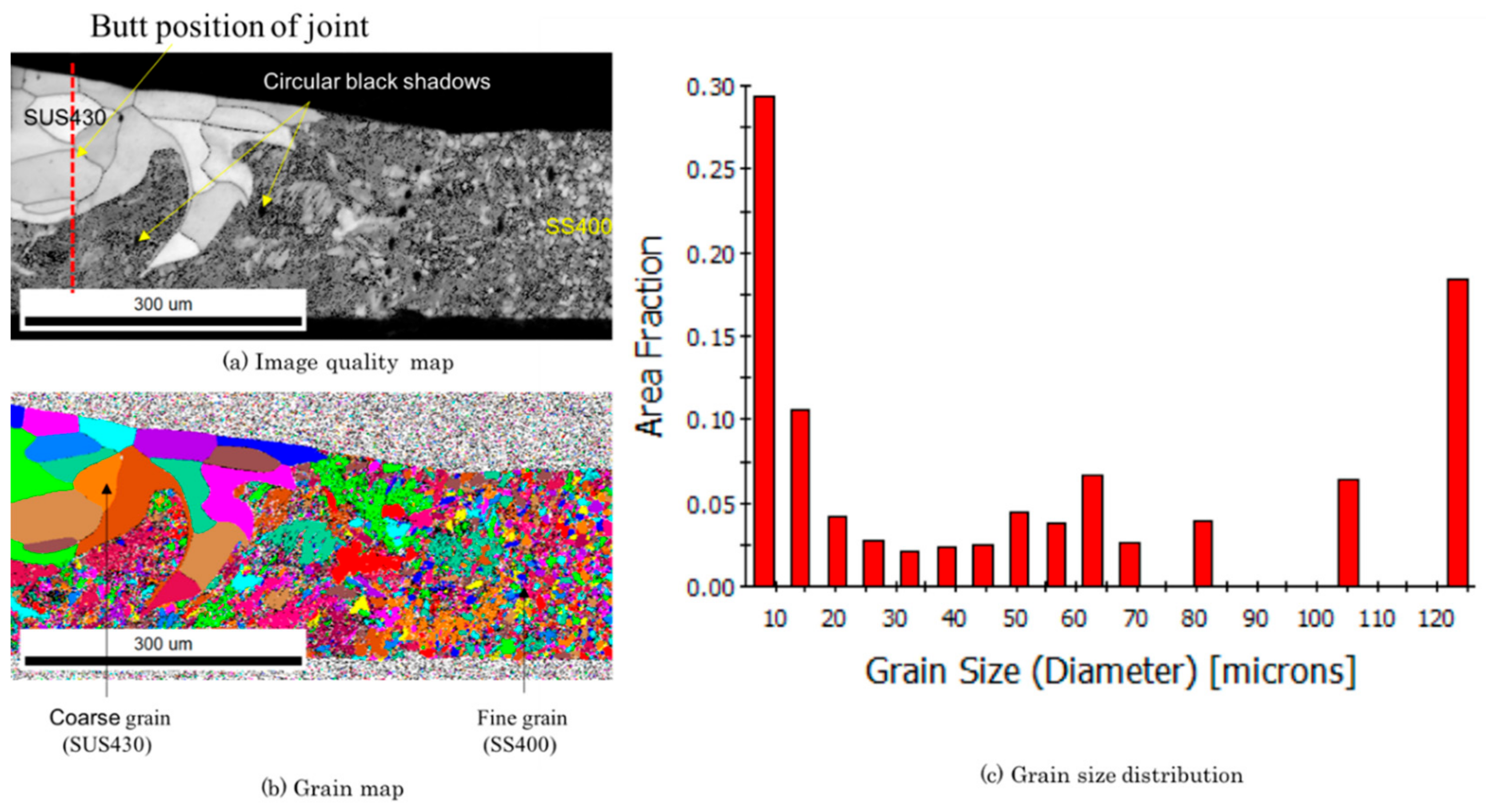
Figure 9 shows the EBSD analysis results in welding SS400 (0.2 mm) and SUS430 (0.4 mm) with low current, 55 A (No.3 case). The left side is the base material of SUS430. The right side is the base material of SS400. Figure 9a is the IQ map. Figure 9b is the grain map. Figure 9c is the grain size. The red dotted line in Figure 9a indicates the butt position of the joint. In this case, circular black shadows can be seen and they are concentrated at the SS400 material side. In addition, it can be seen that the mixture of the materials in the melting zone is not good. The SUS430 material was created a layer on the top surface of the SS400 material. However, on the bottom surface, it seems that only SS400 materials can be seen. The grain on the SS400 side is fine meanwhile it is coarse on the SUS430 side. Furthermore, it seems that no intermetallic layer was formed in this case.
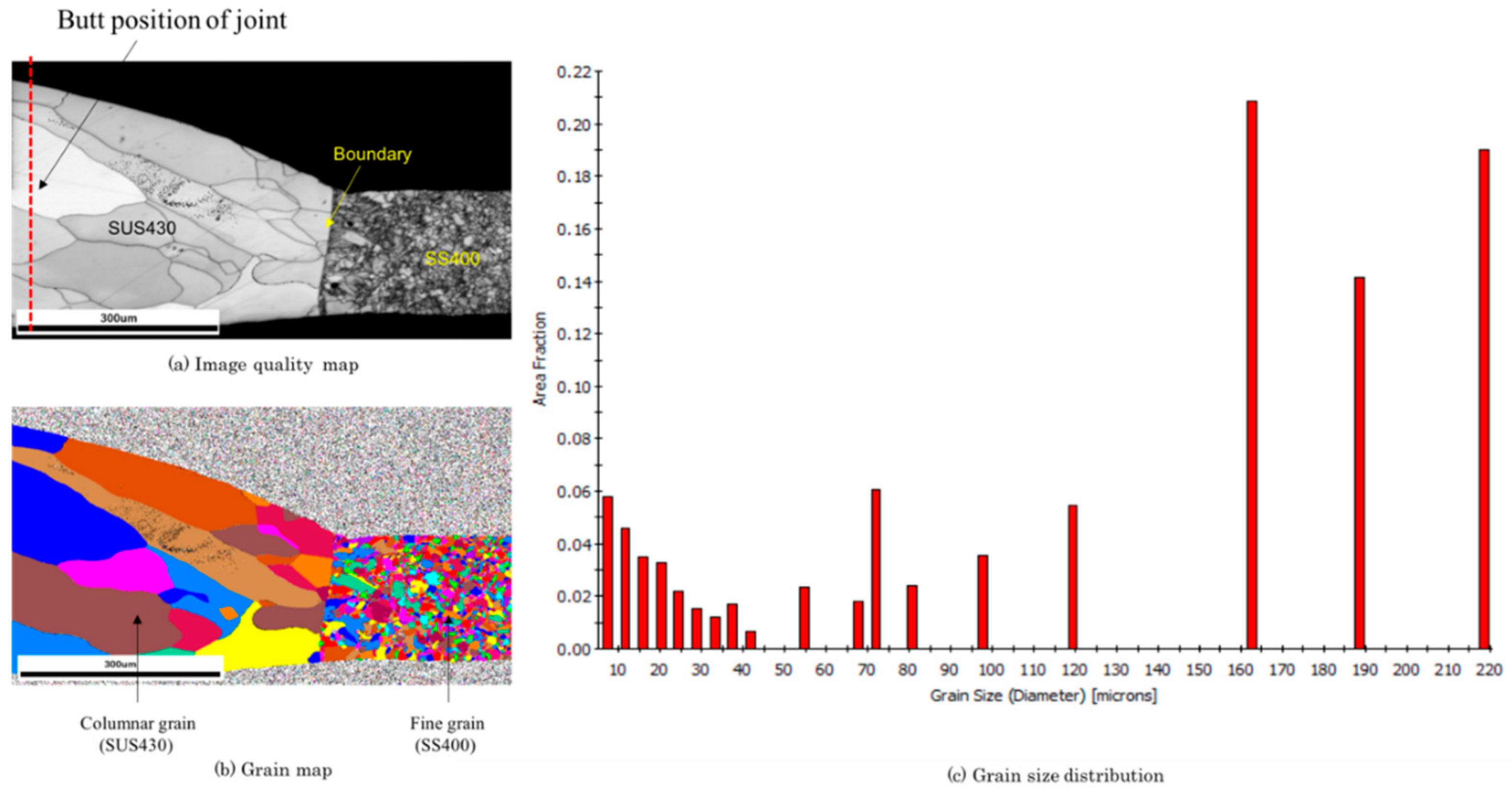
Figure 10 describes the EBSD analysis results in welding SS400 (0.2 mm) and SUS430 (0.4 mm) with high welding current, 65 A (No.4 case). The left side is the base material SUS430. The right side is the base material SS400. Figure 10a is the IQ map. Figure 10b is the grain map. Figure 10c is the grain size distribution. The red dotted line in Figure 10a indicates the butt position of the joint. In this case, circular black shadows were not observed. Moreover, in the melting zone, the SUS430 was penetrated through from the top surface to the bottom surface. The grains were in columnar orientation. The average grain size is larger in comparison to No.3 case. Similarly, in Figure 9, the intermetallic layer was not formed.
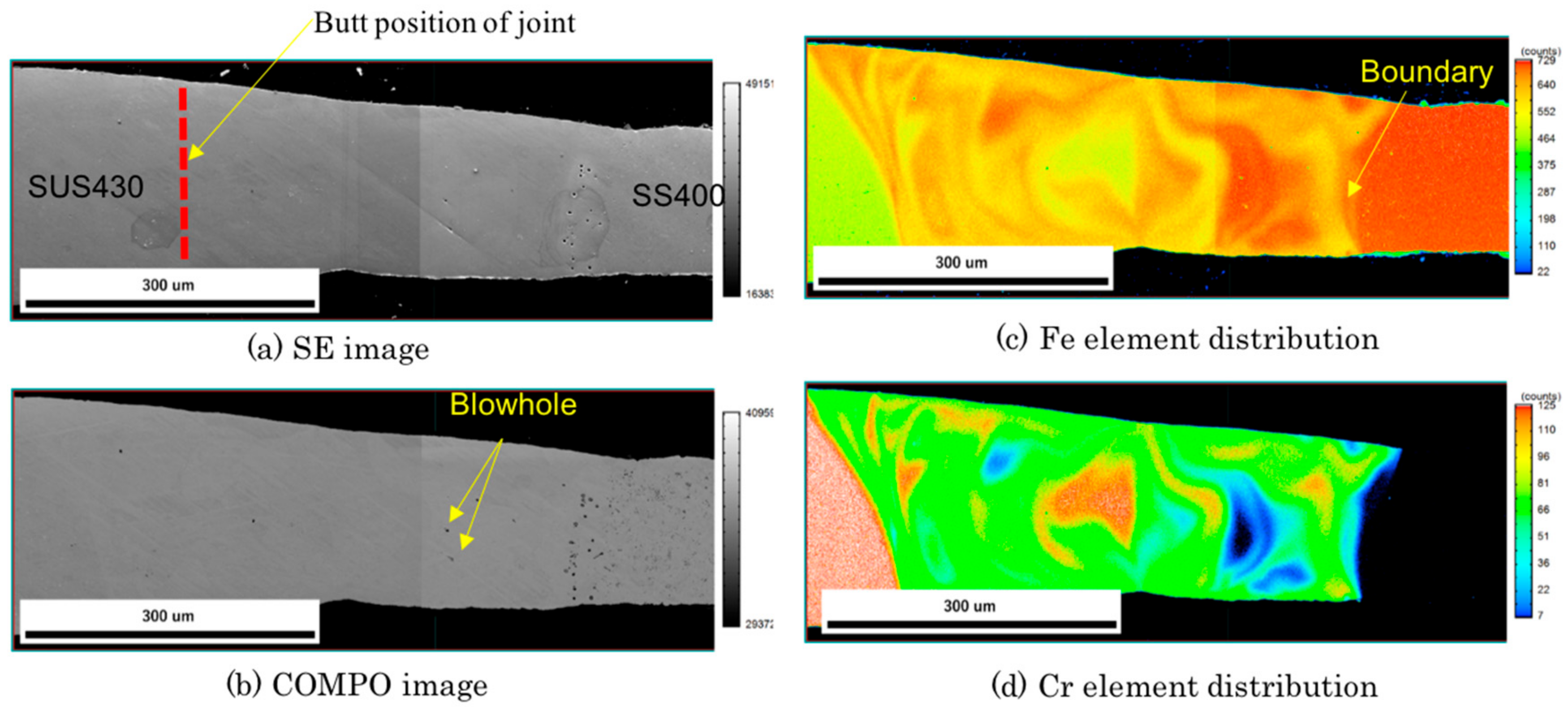
The results of elemental analysis in the No.3 case are exhibited in Figure 11. The left side is SUS430 material. The right side is SS400 material. Figure 11a is the secondary electron (SE) image. Figure 11b is the COMPO image. Figure 11c is the elemental distribution of Fe. Figure 11d is the elemental distribution of Cr. The red line in Figure 11a represents the butt position of the joint. Figure 11a,b show that in several positions of the weld zone on the SS400 material, circular black holes can be seen. Figure 11c indicates that Fe element was distributed with low percent at the SUS430 material side (yellow color) and high percent at the SS400 material side (red color). Figure 11d indicates that Cr was distributed at only the SUS430 material side and it had a slight dilution toward to SS400 materials. However, Cr element was not seen at SS400 material.
Figure 12 shows the results of elemental analysis in case of the welding SS400 and SUS430 with welding current of 65 A (No.4 case). The left side is SUS430. The right side is SS 400. Figure 12a is the SE image. Figure 12b is the COMPO image. Figure 12c is the elemental distribution of Fe. Figure 12d is the elemental distribution of Cr. The red line in Figure 12a represents the butt position of the joint. Figure 12a,b shows that no black holes can be seen. Figure 12c implies that Fe element was distributed with high percent at the SS400 materials side (red color) and with low percent at the SUS430 material side (yellow color). Figure 12d indicates that Cr was distributed on both the SUS430 material side and the weld zone. However, Cr element was not observed at SS400 material. A boundary between the weld zone and the SS400 material was clearly observed (see Figure 12c,d).
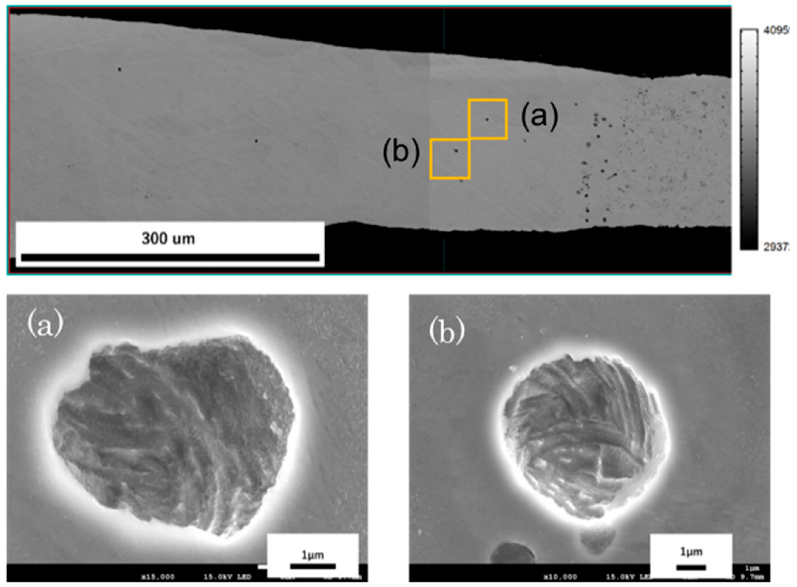
Figure 13 presents a magnified photo of the black shadow in the No.3 case. As shown in Figure 13a,b, black shadows are in circular and regular wave patterns. Furthermore, the analysis results of elements indicated that only Fe element can be detected and no other elements can be found out inside the black shadow. From this result, it can be considered that the black shadows are blowholes.
4. Discussion
4.1. Formation of Weld Beads
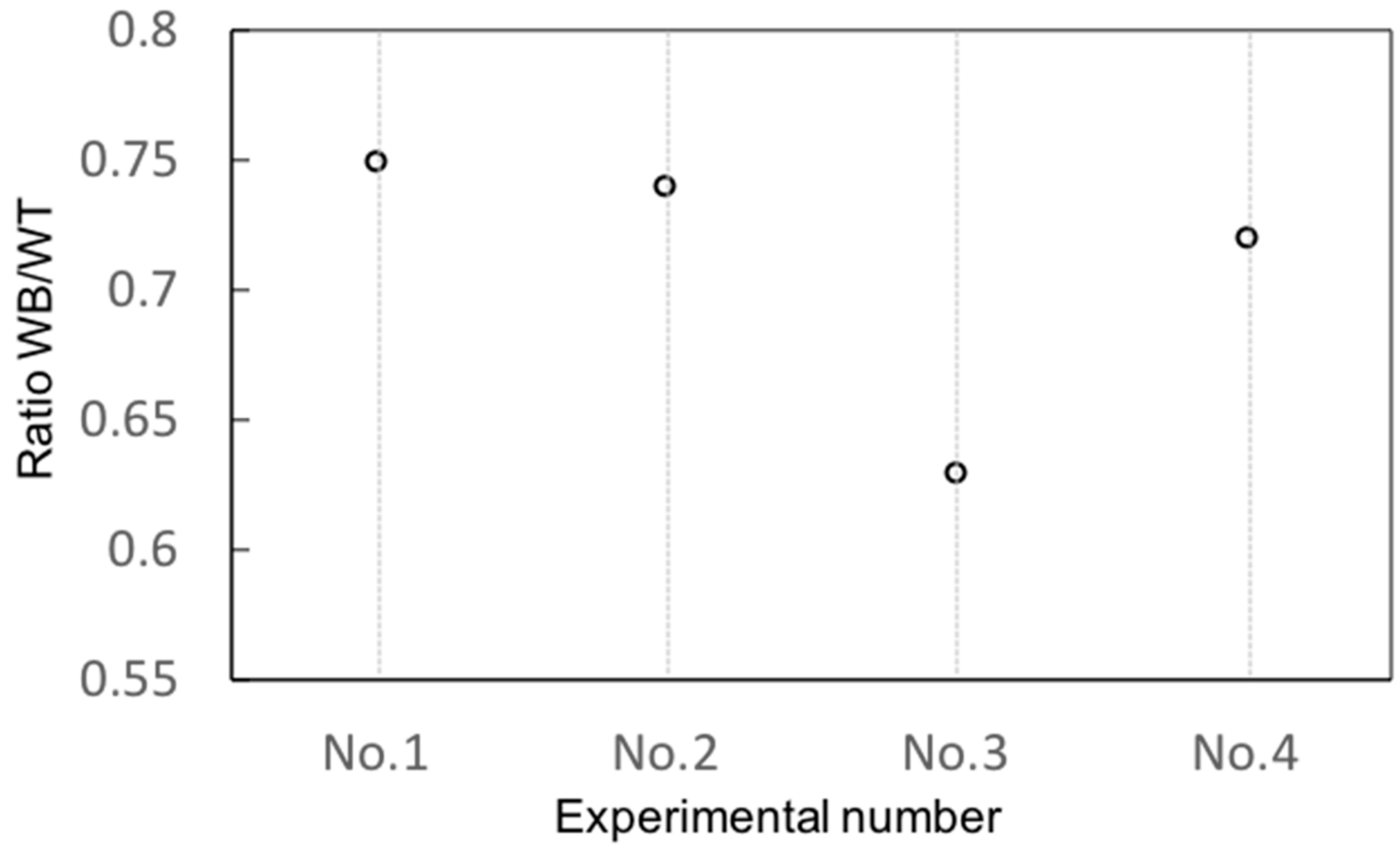
From the results of this paper, it can be considered that butt-joint thin plates can be done well by a new variation of TIG welding technology. The width of the weld bead seems to be stable. No welding defects such as burn-through or under cut were seen on both the top surface and the bottom surface. The ratio of width on the bottom surface (WB) to width on the top surface (WT) is indicated in Figure 14.
Generally, for the conventional TIG welding process, the top surface is much wider than the bottom surface in the full penetration case [16]. In other words, the WB/WT ratio is very small in the case of conventional TIG welding. This means that the heat input is concentrated almost completely on the top surface. However, as it can be seen in this paper, this ratio was about 0.65–0.75. This is much higher than the case of the conventional TIG welding process. It means that the width on the bottom surface was much larger than that in the case of the conventional TIG welding process. This can be explained due to the high heat flux and strongly plasma jet caused by the constricted nozzle.
4.2. Formation of Blowhole
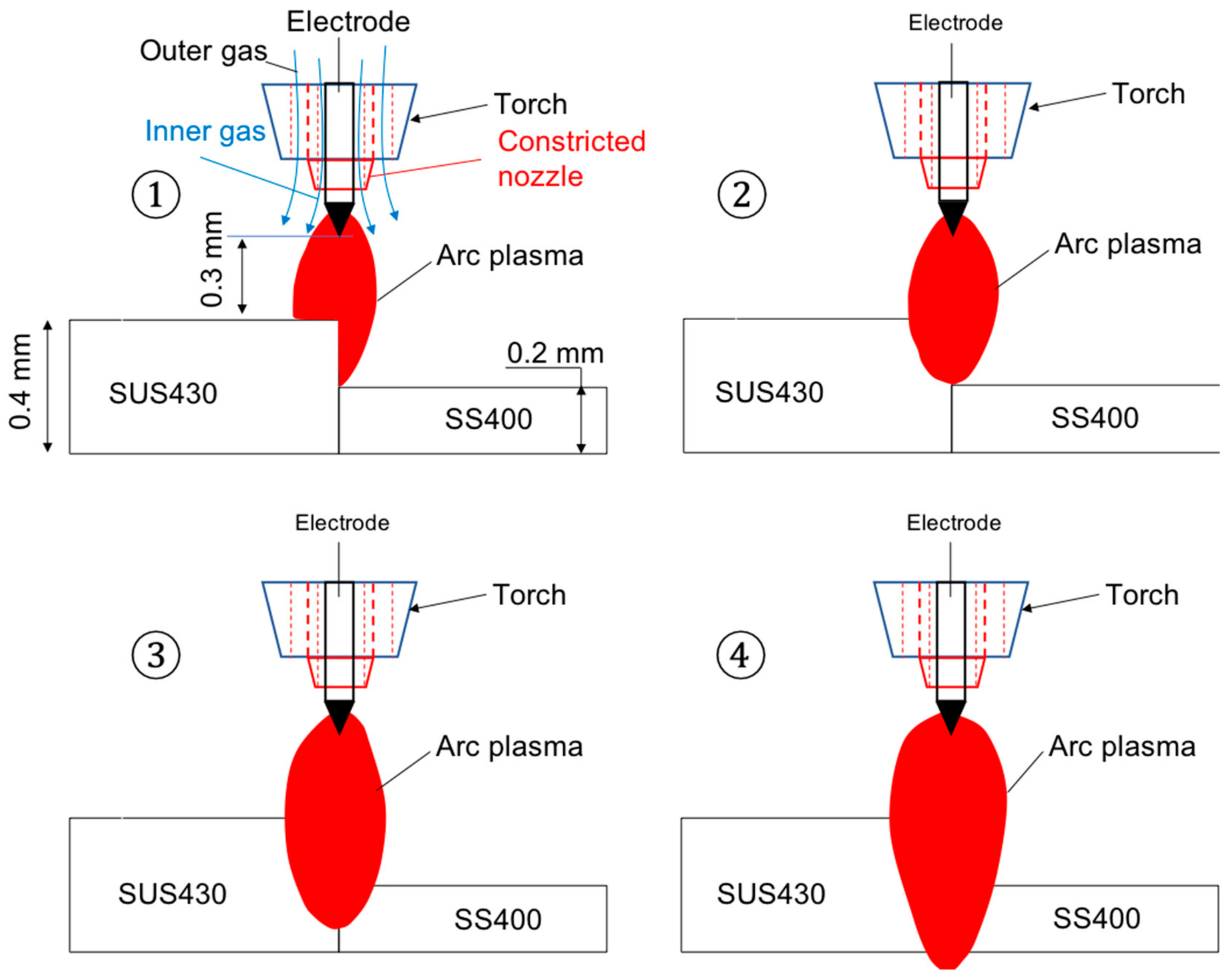
From results above, it can be considered that the thermal diffusion to the surroundings was prevented because of the shortening of the arc length; therefore, there was only a narrowing zone in which grain growth was occurred. Therefore, it can clearly be seen that there is an interface (boundary) between SS400 and SUS430, as showed in Figure 11 and Figure 12. From Figure 9 (No.3 case), in this case of welding with a low welding current (55 A), it seems that the heat input is not enough to fuse the base metal at the bottom surface. As a result, SUS430 was only diffused on the top surface but it was not seen at the bottom surface. As showed in the Results section, no blowhole was found out in the weld zone in cases No.1, No.2 and No.4. However, blowholes can be seen clearly in case No.3. Generally, it is thought that blowholes occur in the entire molten metal due to a low heat input. However, Figure 9 and Figure 11 show that the blowholes are concentrated at only the side of the base material SS400. This can be explained by the mechanisms from ① to ④ as implicated in Figure 15. Firstly, the heat from the arc plasma reaches the surface of SUS430 materials, and then SUS430 starts to be in a fusion situation (see ①). After that, the molten metal SUS430 is pressed by the arc plasma, as showed in ②. In this stage, most of the heat input is supplied for the SUS430 material and a minor amount of the heat input is supplied for the surface of SS400 material. Next, the heat input causes melting of both materials with a larger amount of melted metal on the SUS430 side, but they are still not penetrated fully, as indicated in ③. Finally, both materials reach full penetration as in ④. The torch was closer to SUS430 because the thickness of SS400 was less in comparison to SUS430. As a result, the heat input is mainly supported at the SUS430 material to procedure a sound bead without welding defect. Meanwhile, insufficient heat input at the SS400 material side caused the blowhole, as in the explanation above.
5. Conclusions
In this paper, a novel TIG welding torch was developed to apply in butt-joint thin sheets. By using a constricted nozzle, the arc plasma was stable and its efficiency for joining thin sheets can be seen. Furthermore, the weld bead images were taken to examine the welding defects such as undercut and burn-through. Images of cross-sections of welding samples were also captured to evaluate the welding defects inside the weldment. From the results, the efficiency of this torch was clarified. An acceptable weld bead appearance was seen with unchanged of width overall at the weld seam. The width of the weld bead on the bottom surface was about 0.63–0.75 times the width on the top surface (see Figure 14). In the case of a high welding current, no blowhole inside the weldment was seen. In the case of low welding current, the blowholes were found on the SS400 material side. For the future schedule, we are planning to perform strength tests and hardness tests for examining the mechanical properties of joints.
Author Contributions
N.H.M. wrote the draft and revised the paper; N.V.A. collected the data, wrote the draft, and responded to the journal; N.V.T. supported the funding and checked the draft; B.X. discussed and estimated the efficiency of this technology; M.A. supported the equipment and provided materials for experiments. All authors discussed the results and contributed to the final manuscript.
Funding
No funding support was received for this paper.
Conflicts of Interest
The authors declare that there is no conflict of interest regarding the publication of this paper.
References
- Mehtap, H.; Serce, O.; Karabulut, H.; Ayan, Y.; Kahraman, N. A study on micro TIG tube welding of thin extra aisi 321 austenitic stainless steel sheets. Int. Conf. Technol. Eng. Sci. 2018, 4, 263–270. [Google Scholar]
- Hong, Y.; Chang, B.; Peng, G.; Yuan, Z.; Hou, X.; Xue, B.; Du, D. In-Process monitoring of lack of fusion in Ultra-Thin sheets edge welding using machine vision. Sensors 2018, 18, 2411. [Google Scholar] [CrossRef] [PubMed] [Green Version]
- Batool, S.; Khan, M.; Jaffery, S.H.I.; Khan, A.; Mubashar, A.; Ali, L.; Khan, N.; Annwar, M.N. Analysis of weld characteristics of micro-plasma arc welding and tungsten inert gas welding of thin stainless steel (304L) sheet. Proc. Inst. Mech. Eng. Part L: J. Mater. Des. Appl. 2016, 230, 1005–1017. [Google Scholar] [CrossRef]
- Nobuyuki, A.; Yoshinori, F.; Takashi, I.; Masahiro, T. Micro welding of thin stainless steel foil with a direct diode laser. Trans. JWRI 2005, 34, 19–23. [Google Scholar]
- Kang, N.; Mahank, T.A.; Kulkarni, A.K.; Singh, J. Effects of gravitational orientation on surface deformation and weld pool geometry during gas tungsten arc welding. Mater. Manuf. Process. 2003, 18, 169–180. [Google Scholar] [CrossRef]
- Okamoto, Y.; Matsuoka, S.; Otowa, T.; Okada, A. Influence of bead geometry on weld distortion in laser micro-welding of thin stainless steel sheet with High-speed scanning. Int. J. Electr. Mach. 2015, 20, 9–15. [Google Scholar] [CrossRef] [Green Version]
- Mochizuki, M.; Okano, S. Effect of welding process conditions on angular distortion induced by Bead-on-plate welding. ISIJ Int. 2018, 58, 153–158. [Google Scholar] [CrossRef] [Green Version]
- Han, T.; Wang, Y.; Liu, W. Study on burn-through prediction of In-service welding. Trans. JWRI 2011, 9–12, Specially issue. [Google Scholar]
- Akihisa, M.; Manabu, T.; Shigeru, N. Constricting Nozzle and TIG Welding Torching. U.S. Patent US20130277337A1, 24 October 2013. [Google Scholar]
- Murata, A.; Murata, T.; Tanaka, M. Development and it’s practical application of GTAW automated butt welding equipment for ultra-thin sheet. J. Light Met. Weld. 2013, 51, 56–59. [Google Scholar]
- Tanaka, M.; Tashiro, S. A study of thermal pinch effect of welding arcs. Q. J. JWS 2007, 25, 336–342. [Google Scholar]
- Konishi, K. Study on Arc Heat Source Control in TIG Welding Process. Ph.D. Thesis, Osaka University, Osaka, Japan, 2018. [Google Scholar]
- Kyohei, K.; Masaya, S.; Manabu, T.; Akihisa, M.; Tadasuke, M. Effects of a constricted nozzle on the are phenomena in TIG welding process. Weld. Int. 2016, 30, 590–595. [Google Scholar] [CrossRef]
- Satoshi, M.; Kyohei, K.; Masaya, S.; Manabu, T.; Akihisa, M.; Tadasuke, M. Experimental measurements of gas shielding characteristics in TIG welding with a constricted nozzle. Q. J. Jpn. Weld. Soc. 2018, 36, 21–25. [Google Scholar]
- Anh, N.V.; Akihisa, M.; Tadasuke, M.; Tashiro, S.; Tanaka, M. Influence of welding current on formation of weld bead in TIG welding for joining thin plates. Adv. Eng. Forum 2018, 29, 1–11. [Google Scholar] [CrossRef]
- Fujii, H.; Sato, T.; Lu, S.; Nogi, K. Development of an advanced A-TIG (AA-TIG) welding method by control of marangoni convection. Mater. Sci. Eng. A 2008, 495, 296–303. [Google Scholar] [CrossRef]
Figure 1.
Constricted nozzle and welding torch.

Figure 2.
A Schematic illustration of constricted nozzle tungsten inner gas (TIG) welding process.

Figure 3.
Experimental equipment.

Figure 4.
Experimental process.

Figure 5.
Weld bead appearance.

Figure 6.
Electron back scatter diffraction (EBSD) images of welding SS400 materials (No.1).

Figure 7.
SEM (scanning electron microscope) images of welding between SS400 materials (No.1).

Figure 8.
EBSD images of welding between SUS430 materials (No.2).

Figure 9.
EBSD images of welding SS400 and SUS430 materials (No.3).

Figure 10.
EBSD images of welding SS400 and SUS430 materials (No.4).

Figure 11.
Elemental analysis images of welding SS400 and SUS430 materials (No.3).

Figure 12.
Elemental analysis images of welding SS400 and SUS430 materials (No.4).

Figure 13.
Magnified images of blowhole inside the weldment in the case of No.3. (a): SEM-X15000 and (b): SEM-X10000).
Figure 13.
Magnified images of blowhole inside the weldment in the case of No.3. (a): SEM-X15000 and (b): SEM-X10000).

Figure 14.
Ratio of width on top surface to width on bottom surface.

Figure 15.
Prediction of the blowhole formation process.


Table 1.
Base materials and welding conditions.
| No. | Thickness (Material) [mm] | Welding Current [A] | Welding Speed [mms−1] | Arc Length [mm] |
|---|---|---|---|---|
| No.1 | 0.2 (SS400)–0.2 (SS400) | 22 | 500 | 0.3 |
| No.2 | 0.4 (SUS430)–0.4 (SUS430) | 55 | 500 | 0.3 |
| No.3 | 0.2 (SS400)–0.4 (SUS430) | 55 | 500 | 0.3 |
| No.4 | 0.2 (SS400)–0.4 (SUS430) | 65 | 500 | 0.3 |
Table 2.
The chemical compositions of SS400 and SUS430.
| Elemennts | Fe | C (%) | Mn (%) | Si(%) | Cr (%) | P(%) | S(%) |
|---|---|---|---|---|---|---|---|
| SS400 material | Bal. | <0.12 | <0.95 | <0.30 | - | <0.05 | <0.05 |
| SUS430 material | Bal. | <0.10 | <1.00 | <0.70 | 16–18 | <0.05 | <0.05 |
© 2019 by the authors. Licensee MDPI, Basel, Switzerland. This article is an open access article distributed under the terms and conditions of the Creative Commons Attribution (CC BY) license (http://creativecommons.org/licenses/by/4.0/).
Share and Cite
MDPI and ACS Style
Huu Manh, N.; Van Anh, N.; Van Tuan, N.; Xu, B.; Akihisa, M. Research and Development of a Novel TIG Welding Torch for Joining Thin Sheets. Appl. Sci. 2019, 9, 5260. https://0-doi-org.brum.beds.ac.uk/10.3390/app9235260
AMA Style
Huu Manh N, Van Anh N, Van Tuan N, Xu B, Akihisa M. Research and Development of a Novel TIG Welding Torch for Joining Thin Sheets. Applied Sciences. 2019; 9(23):5260. https://0-doi-org.brum.beds.ac.uk/10.3390/app9235260
Chicago/Turabian StyleHuu Manh, Ngo, Nguyen Van Anh, Nguyen Van Tuan, Bin Xu, and Murata Akihisa. 2019. "Research and Development of a Novel TIG Welding Torch for Joining Thin Sheets" Applied Sciences 9, no. 23: 5260. https://0-doi-org.brum.beds.ac.uk/10.3390/app9235260
Note that from the first issue of 2016, this journal uses article numbers instead of page numbers. See further details here.