Article

The Contribution of the Segovia Mint Factory to the History of Manufacturing as an Example of Mass Production in the 16th Century

by
Francisco García-Ahumada
* and
Cristina Gonzalez-Gaya
*
Department of Construction and Manufacturing Engineering, ETSII-Universidad Nacional de Educación a Distancia (UNED), C/Juan del Rosal 12, 28040 Madrid, Spain
*
Authors to whom correspondence should be addressed.
Submission received: 1 October 2019 / Revised: 22 November 2019 / Accepted: 26 November 2019 / Published: 7 December 2019

Abstract

:
A new means of minting currency was first used at the Hall Mint in Tyrol in 1567. This new minting process employed a roller instead of a hammer and used hydropower to fuel the laminating and coining mills, as well as ancillary equipment, such as the forge or the lathe. In 1577, Philip II of Spain expressed his interest in the new technology and, after a successful technology transfer negotiation with the County of Tyrol, Juan de Herrera was commissioned to design a factory to accommodate this new minting process. The resulting design seamlessly integrated this new technology. The architectural layout of the factory was derived from the integration of different trades related to the manufacturing workflow, and their effective distribution within a more effective workplace allowed for better use of the hydraulic resources available, and, thus, improvements in the productivity and reliability of the manufacturing process, as well as in the quality of the finished product. Juan de Herrera’s design led to the creation of a ground-breaking manufacturing process, unparalleled in the mint industry in Europe at the time. Segovia Royal Mint Factory (SRMF), as one of the first examples of mass production in the proto-industrial stage, represents a historic landmark in its own right. The objective of this article is to analyse the design of the SRMF to highlight its main innovations. For this purpose, the abundant literature on this project will be reviewed.

1. Introduction and Goals

The Segovia Royal Mint Factory (SRMF) has its origins in King Philip II of Spain’s demand for a founder for the manufacture of cannons. In a letter dated 23 October 1574, the King stated that “«In these Realms there is a need for a couple of good artillery founders that they tell me tend to live in Nuremberg …»” [1]. In 1577, this search led the King to the discovery of a new minting process, which had replaced the former minting process that involved using a hammer.
This new minting process was developed at Hall Mint, in 1571, and used a roller instead of a hammer. The main advantage of this new manufacturing process, and what made it so attractive to the crown of Spain, was its ability to maintain uniform weight, thickness, quality of type, engraving and precision parameters in every coin produced, which, in turn, made illicit activities such as clipping and filling incredibly difficult.
Figure 1 presents two images. The first corresponds to a coin minted (Real de a ocho) in the mechanized SRMF of Segovia in 1627, and the second to a “Real de a ocho”, minted by a hammer, in the Casas Vieja (The effects of the clipping on the coin can be seen, in relation to the left coin) mint of Segovia, in 1627 [1,2,3].
Negotiations between the County of Tyrol and the Kingdom of Spain, regarding the transfer of technology, were initiated in 1581. The final approval of the agreement, allowing the introduction of the roller-based minting process in Spain, is detailed in a letter located in Innsbruck, dated 4 February 1582. In it, Archduke Ferdinand, cousin of King Philip II of Spain, gives Baron Khevenhüllern, Imperial Ambassador at the court of Philip II, permission to communicate the success of the negotiations to the Crown of Spain [2].
The SRMF project began development in 1582, during what is known as the proto-industrialization stage [4]. The SRMF would become one of the first European factories. It stayed operational from 1586 to 1866. In 2012, it became a museum.
Several innovations appear during the development of this project, which make it unique in the history of manufacturing. The most relevant are:
  • Technology transfer process. The SRMF Project is based on a technology transfer agreement between two nations.
  • Multinational project teams. In this project, they had to coordinate a multinational team for its development and operation.
  • Transportation Logistics. This project required a logistic transport model for the supply of machines and engines for manufacturing.
  • Architectural layout. An architectural design aligned with the mass manufacturing process, two centuries before the industrial revolution at the time of proto-industrialization [4,5].
  • Hydraulic model. A hydraulic model to supply energy for the manufacturing process.
In the following sections, the following aspects of the SRMF Project will be analysed:
  • The scope of the work and the project team.
  • The stages of the project.
  • The design and construction of the SRMF, serving as an example of an alignment between manufacturing methods and architectural layout.
The focus of the article is to analyse the different innovations of the SRMF project.

2. Materials and Methods

The material used is the existing bibliography of the sections mentioned above, which has been selected based on the analysis of the innovations already mentioned.
The methodology is formed of an analysis of the verified facts. In the analysis of the bibliography of this project, we have searched for the relevant innovations throughout the history of the industry.

3. Results

The order of the results will follow the order indicated in the introduction.

3.1. The Scope of Work and the Project Team

The Segovia Royal Mint Factory project started with an international technology transfer agreement, involving the County of Tyrol—under the control of Archduke Ferdinand—and the Kingdom of Spain—under the rule of King Philip II. The scope of the SRMF project can be divided into two parts.
The first part is formed of the transfer of the roller-based minting process, the manufacture of the rolling mills and other necessary machinery at the Hall Mint in Tyrol and the transportation of the equipment, along with its operators, to Spain.
The technology transfer agreement is notable, since it is a contract between two countries in which a technology is transferred through its equipment and tools, as well as the workers necessary to its operation, as skilled Austrian workers accompanied the machinery on its trip to the Kingdom of Spain.
The second part is formed of the design and construction of the SRMF facilities, as well as the selection of a suitable site for the factory. The factory had to be comprised of a building, or a series of buildings, which were able to accommodate all the elements necessary for autonomous operation, including all the mechanical equipment involved in the manufacturing process powered by hydraulic energy.
After the signing of the technology transfer agreement in 1582, a team of experts from both countries were gathered to develop and manage the SRMF project. The Crown of Spain provided:
  • Juan de Herrera, appointed as project leader due to his experience in both architectural and engineering projects. Of particular relevance to this project was his previous experience in water conveyance and hydraulic networks, as well as his participation, along with Jacome da Trezzo, in 1579, in the design and construction of the Jasper Mill, which was used to cut hard stones for the Monastery of El Escorial [6].
  • Francisco Ribera, the “Veedor”, or Crown’s Representative, in the project, and in charge of the project’s economic aspects.
The County of Tyrol provided a team of six German technicians: a master teacher, three carpenters, a blacksmith and a locksmith. They were sent to Spain to provide technical support from the early stages of the project, in fulfilment of the terms of the technology transfer agreement [7].
The launch of the project began with the arrival of the German technicians in Spain, in April 1582.

3.2. The Stages of the SRMF Project

In the following sections, the different stages of the SRMF project will be analysed.

3.2.1. Site Selection

Although the different criteria for site selection are not analysed in this paper, it is worth pointing out the importance of the availability of a constant flow of water throughout the year. Consequently, Segovia was the chosen location, despite Seville being the entry point for the precious metals coming from the Americas, which seemed a more logical option at first. More information on the subject can be found in [8].
The selected plot was located adjacent to the Santa Maria del Parral Monastery, along the Eresma river. A mill used to produce paper was already situated in this location—the Mill of San Millan. According to the Land Registry (reference number 5145601VL0354N), it had a total area of 7635 m2.

3.2.2. Manufacture of the SRMF’s Machinery

The transportation of machinery and ancillary equipment from the Hall to Segovia was one of the most challenging stages of the SRMF project, when considered from a logistical perspective [9]. Given the distance (approximately 2000 km) between both cities, the difficult orography of some of the areas, and the large amount of equipment needing to be transported—25 carts were necessary, once everything was carefully packaged, to avoid any damage—the Spanish Road [10] was the chosen route, for safety reasons. Some members of the Hall Mint staff—an assayer, an engraver, a coin master, a founder and four coin technicians—were sent along for equipment installation, operation and personnel training purposes.
The journey was divided into three legs. Starting in Hall, the first leg was overland and had three stopovers: Como, Milan and Genoa. The second leg was the journey between Genoa and Barcelona, and was done by sea, while the last part of the trip, from Barcelona to Segovia, was an overland journey. The journey took from October 1584 to June 1585 [9]. Due to its magnitude, this trip can be regarded as a milestone in the history of logistics.

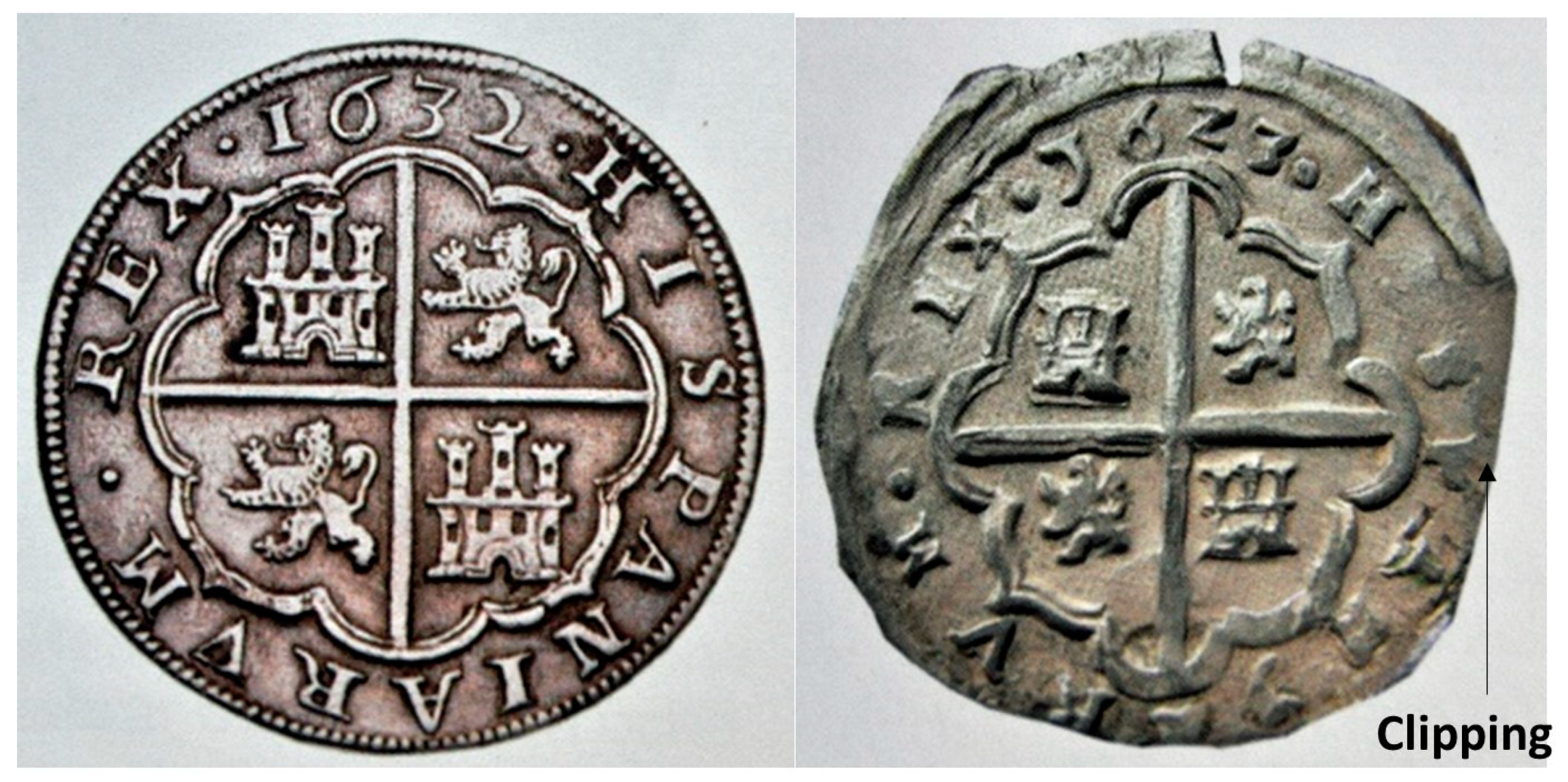
3.2.3. Start-Up Tests and First Minting

With the arrival of the equipment in June 1585, and the team of technicians that travelled with it, the installation of the machinery in the SRMF facility began, quickly followed by start-up tests and the first minting (shown in Table 1).
Once the operation procedure was implemented and refined, the members of Hall Mint proceeded to transfer their knowledge to local personnel. Their technology was replicated in all the minting factories and abandoned in the period 1660–1664. Only the rolling process persisted through the transition of the coining press into flywheel presses [9].

3.3. The Design and Construction of SRMF

The SRMF was among the first mechanized factories dedicated to coin minting in Europe in the 16th century, and the first of its kind in the Kingdom of Spain. It was built on a plot located by the Eresma River in Segovia. The plot had an existing building, an old mill used to produce paper, and a total surface area of 7635 m2. The requirements of the project consisted of a facility able to accommodate all the elements necessary to operate autonomously, with all the mechanical equipment involved in the manufacturing process powered by hydraulic energy.
Juan de Herrera employed an innovative but rather unusual approach in the design of the architectural layout of the SRMF; he analysed the new minting process in depth and, relying heavily on the technical advice provided by the support team of German technicians, integrated the different trades related to the manufacturing workflow and arranged them in an effective workplace distribution, which allowed for better use of the hydraulic resources available and generated significant reductions in both cost and time.
In the following sections, we will review the minting process by roller and how it relates to the architectural layout designed by Juan de Herrera, as well as the hydraulic system designed to power the mechanical elements of the factory.

3.3.1. The Minting Process by Roller and the SRMF Architectural Layout

The different activities related to the minting process by roller can be grouped into the following categories:
  • Intrinsic: All activities related to the process of creating alloys and casting the alloy strips from which coins were manufactured.
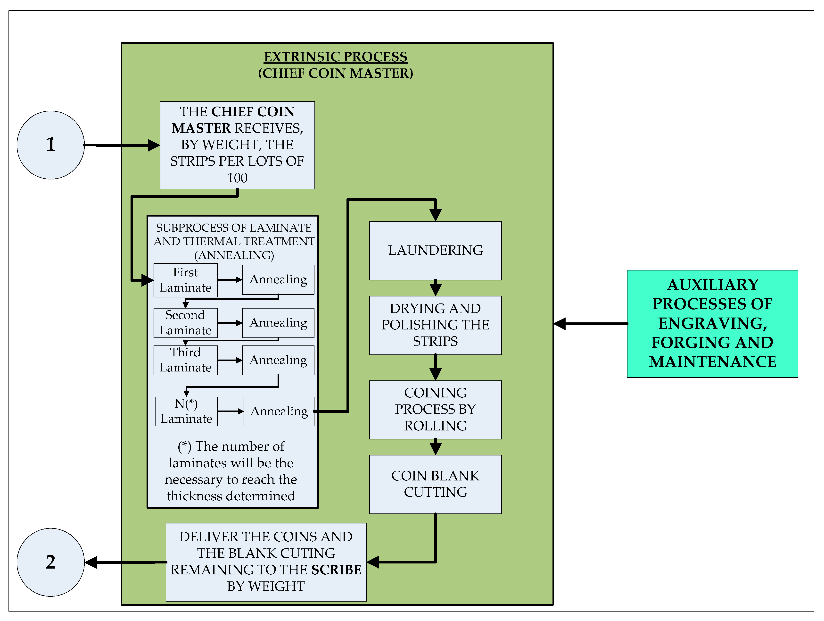
  • Extrinsic: Tasks associated with the mechanical, thermic and chemical treatments applied to the alloy strips used in the manufacturing of currency.
  • Auxiliary: Includes activities connected to machinery maintenance, as well as engraving, forging and lathing processes.
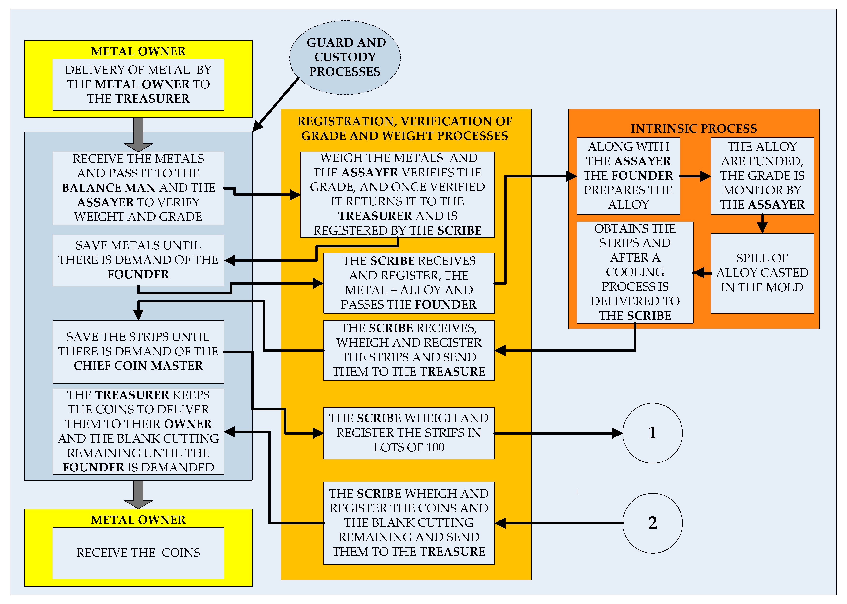
  • Administrative: This category can be divided into two subgroups. The first includes all activities related to the guard and custody of raw materials (metal ingots), alloy strips, coins and metal alloy scraps generated by the blank cutting process, while the second encompasses all activities linked to the registration and verification of the weight and quality (also called Law) of the metals employed to create the alloys, as well as the alloy strips, coins and metal alloy scraps resulting from the blank cutting process.
A list of the roles necessary for the operation of the SRMF, along with a brief description of their corresponding duties, is displayed in Table 2, below.
The sequence of activities that make up a cycle in the production of currency at the SRMF, from the beginning—when the raw material, metal, enters the production chain—until the end of the manufacturing process—when the final product, in the form of coins, is obtained—is shown in the flow charts of Figure 2 and Figure 3. Both charts have been based on those shown in [2], on pages 60 and 61.
The resulting design by Juan de Herrera had a built surface of 4.423 m2 and was made up of three buildings (see Figure 4). The first was called “Edificio del Patio Alto”, and the other two were called “Ingenio Grande” and “Ingenio Chico”. A water system located between the “Ingenio Grande” and “Ingenio Chico” buildings channelled water to power the waterwheels, located along the façade of the “Ingenio Grande”.
The activities that made up the currency-minting production chain were organized among the different buildings of the SRMF, as follows:
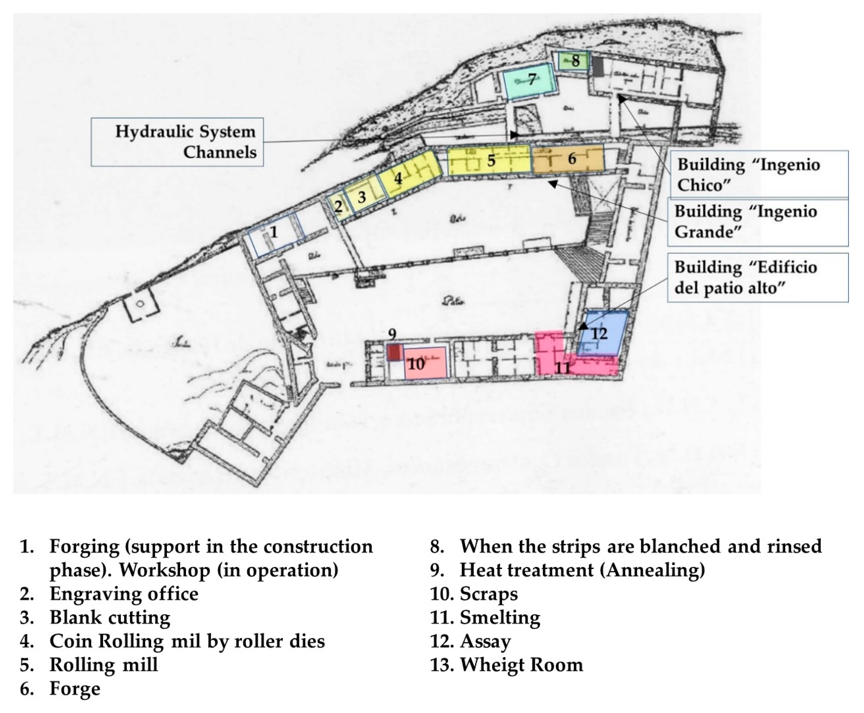
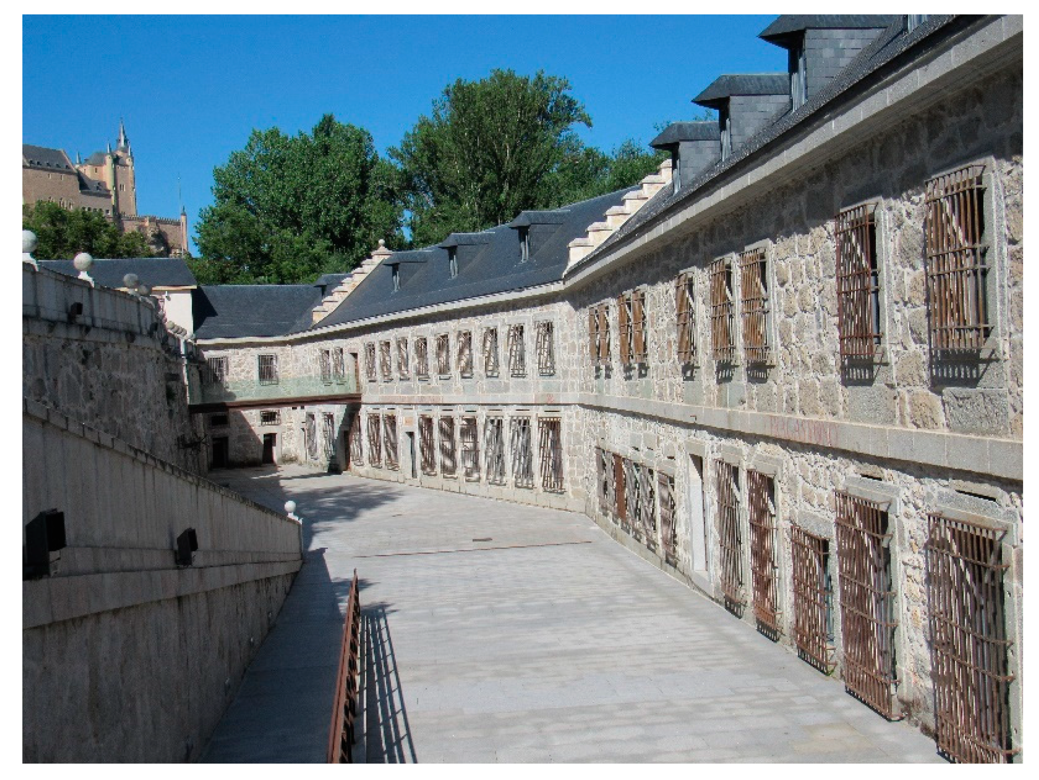
Edificio del Patio Alto: This building was the SRMF management headquarters, and, until 1730, it was run by the Treasurer. This was where the input of raw material, (metal ingots) and the output of finished product (coins), took place, and where administrative and intrinsic activities were carried out. From the moment the metal ingots entered the production cycle, each stage of the process was carefully registered and controlled: the registration and verification of the grade and weight of metal used to cast the alloy strips, the alloy strips themselves and the coins obtained from them. From this building, the alloy strips were sent to the “Ingenio Grande” and came back in the form of coins and alloy scraps.
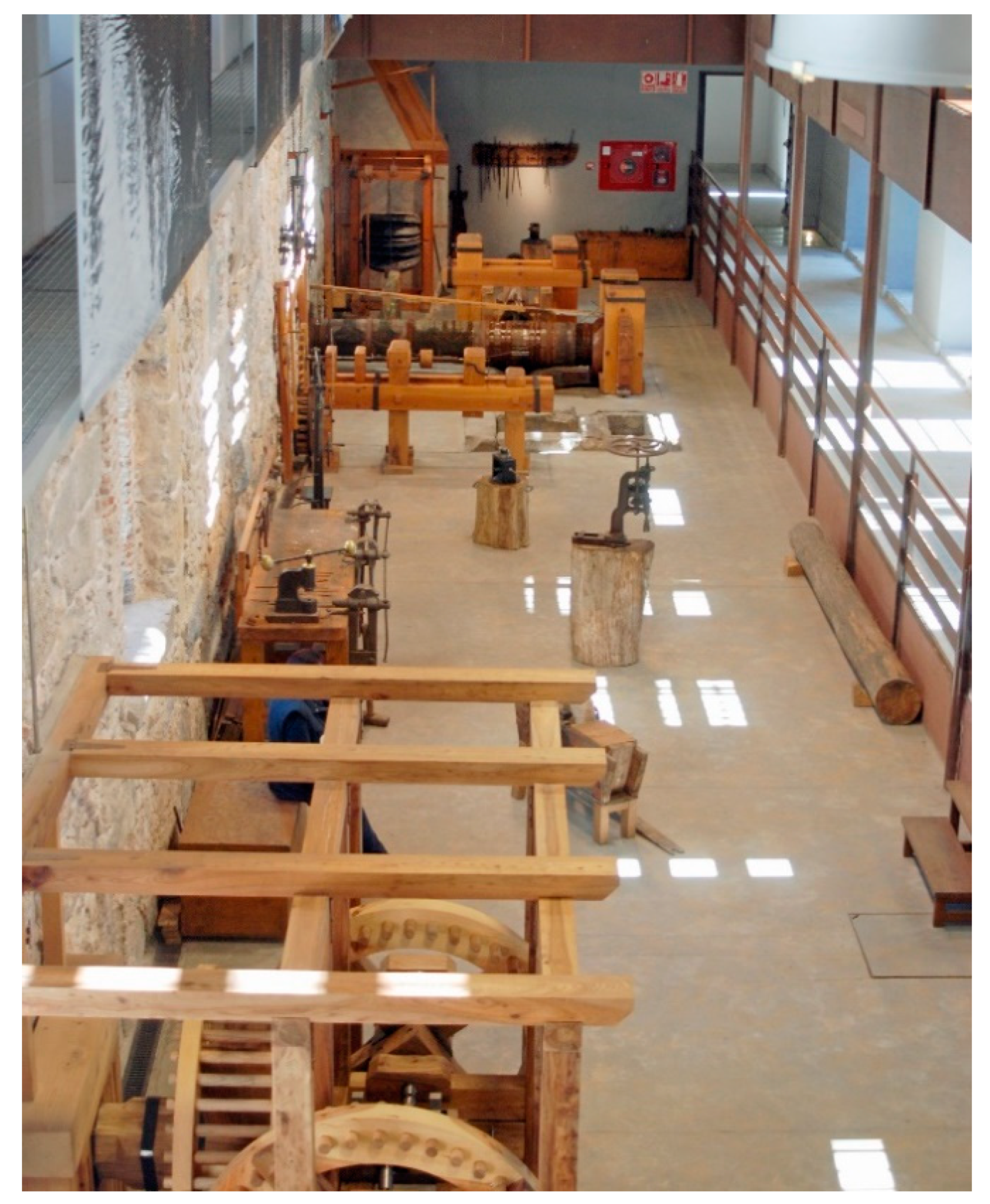
Ingenio grande: This was the biggest of the three buildings, and it was managed by the Coin Master. Mechanical and auxiliary processes were developed here (see Figure 5).
The fact that the equipment necessary to perform such activities had to be powered by hydraulic energy affected the arrangement of the different activities within the space. A sequential order was followed, based on the manufacturing process. A series of waterwheels were installed outside—along one of the longer walls—to power the forge blower, the hammer, the lathe, the rolling mill and the coin die machine (see Figure 6).
The different functional areas within the building were the following:
  • The Forging Shop Area: This stretched along the first three waterwheels, which powered the forge, hammer and lather. It was where the auxiliary processes supporting the manufacturing activity were performed.
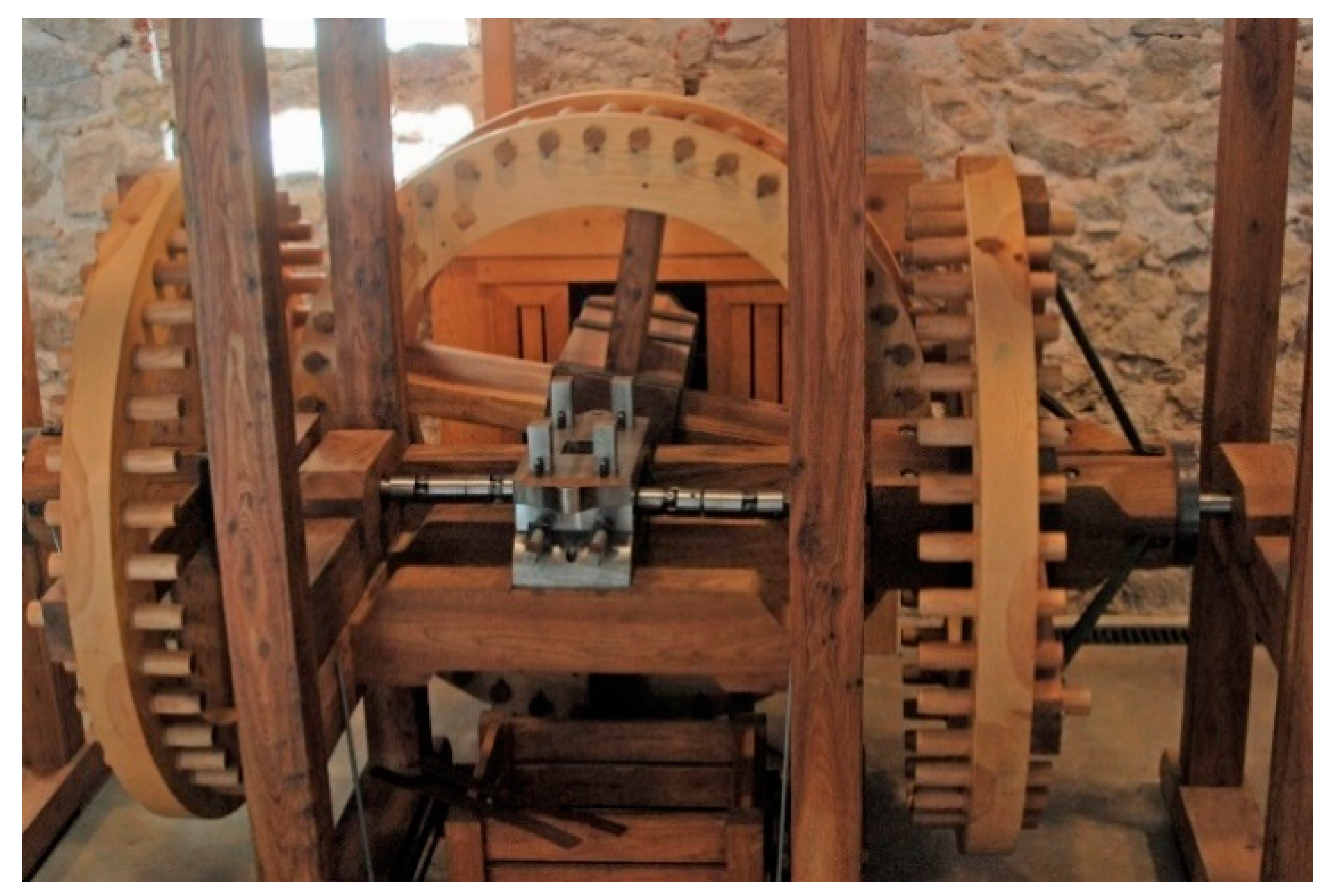
  • Laminating Rolling Mill Area: This accommodated the rolling mills that were manufactured in the Hall. It was where alloy strips were subjected to successive processes of lamination, in order to reach the desired thickness. This area was linked to the “Ingenio Chico” building, since the strips were constantly moving between both buildings to alternate the lamination processes with the thermic treatment meant to restore their mechanical properties.
  • Coin Rolling Mill Area: This contained a rolling mill with a coin die installed, which was used to print both sides of the coin on the strip simultaneously (see Figure 7).
  • A virtual reconstruction of the laminating and coin mill area can be seen in Figure 8.
  • Blank Cut Area: This is where the blank cutting press was used to cut the coins out. Once this process was finished, the coins that were obtained and the alloy scraps generated were sent back to “Edificio del Patio Alto”.
  • Engraving Area: This is where the engraver produced the different stamp punches.
  • Mechanics Workshop Area: This area was dedicated to the performance of all maintenance tasks, especially those related to the water system. It was run by the Waterwheel Master.
  • Ingenio Chico: This corresponded to the old San Millan Mill that was part of the original site. The building was repurposed to accommodate the thermal and chemical treatments given to the alloy strips, the former being the annealing process and the latter, the laundering process. The annealing was a thermic treatment, aiming to restore the mechanical properties of the alloy strips at the end of each lamination process they were subjected to, while the laundering was a chemical treatment, meant to whiten the alloy strips, which darkened after rounds of lamination and annealing. This building was also run by the Coin Master.

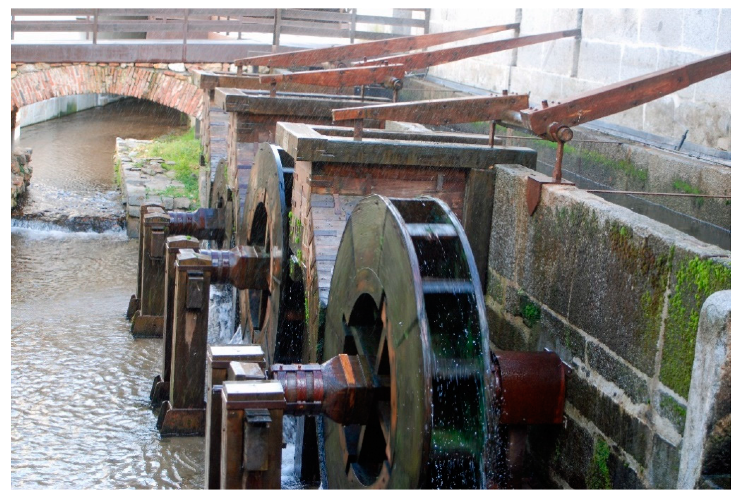
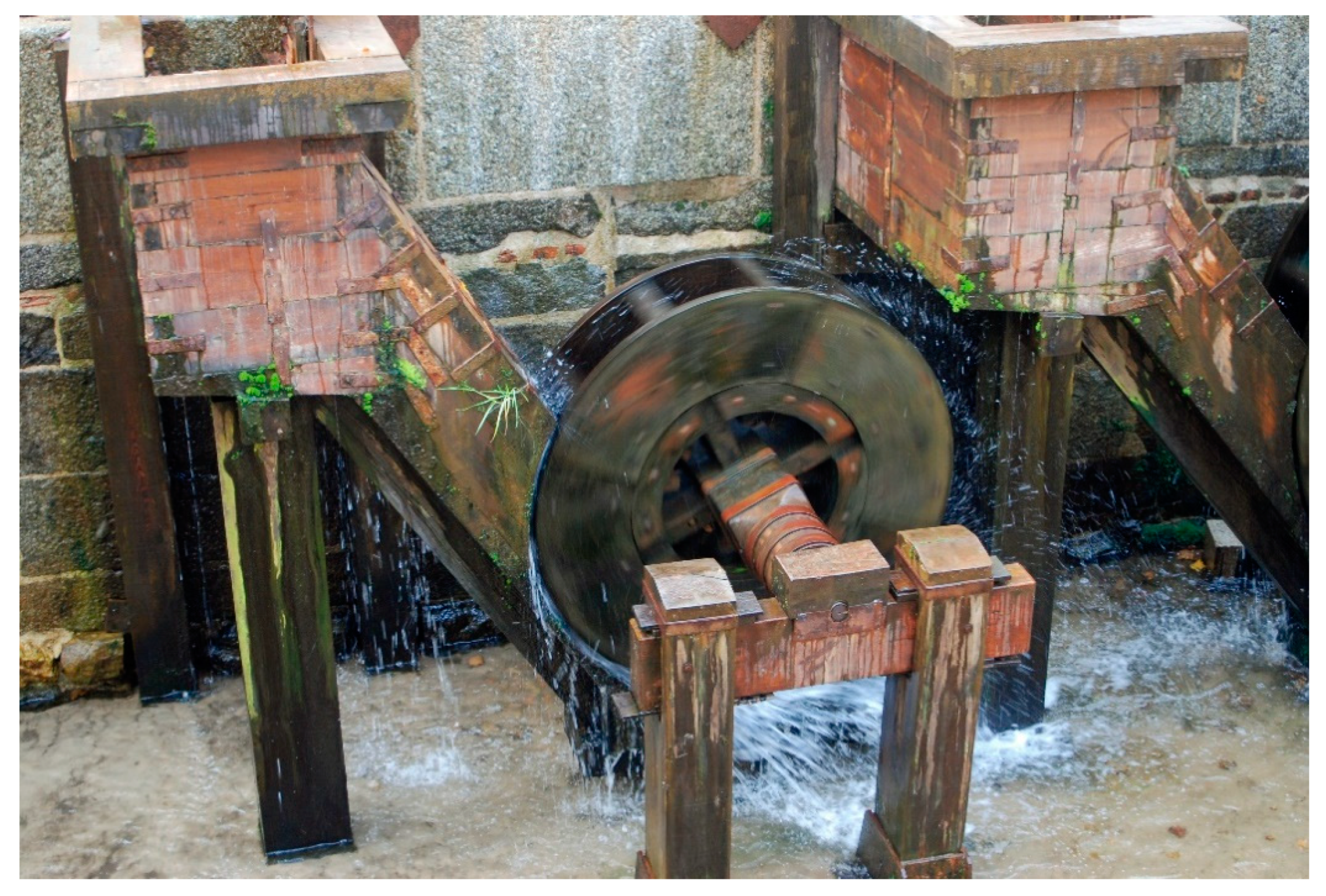
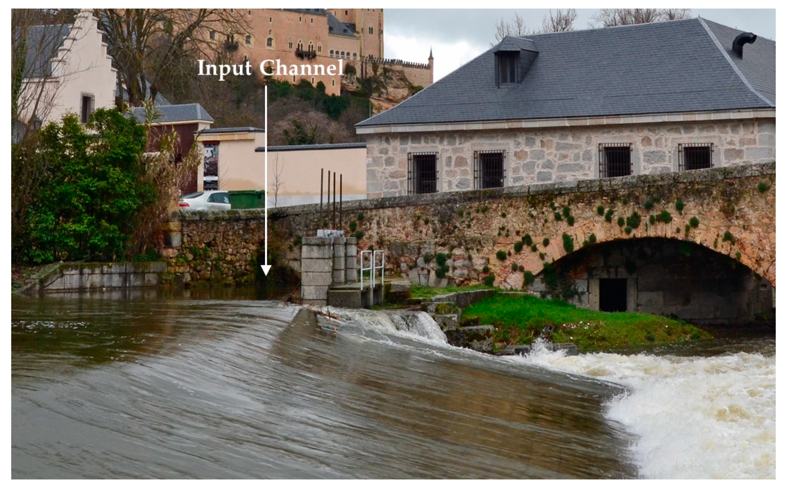
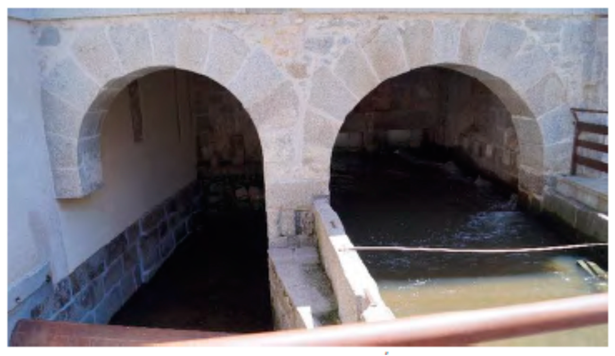
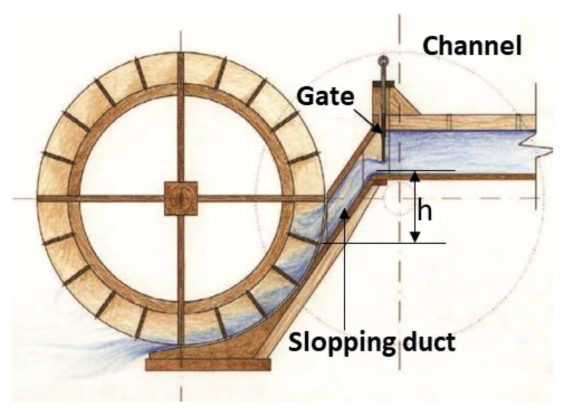
3.3.2. The SRMF Hydraulic System

The water system’s ability to harness the Eresma River flow, in order to convey the hydraulic energy required to power the equipment related to mechanical and auxiliary processes, was key to the successful operation of the SRMF. The goal of Juan de Herrera’s water system design was to adapt the existing structure, which had served the old San Millan Mill, to the more demanding requirements of the SRMF.
The original gravity dam, with an arched floor and lateral drainage located in the left abutment, manually regulated by two gates, was modified to incorporate an outlet meant to divert enough of the Eresma River flow to actuate the waterwheels placed along the façade of the Ingenio Grande (see Figure 9 and Figure 10). The surplus capacity of the bypass channel was designed to be poured by coronation (see Figure 11 and Figure 12). This system was intended to reduce the number of waterwheels used, in case of a decrease in flow availability caused by intense drought [13].

The Waterwheels

The wheels were designed to supply the power necessary to move the manufacturing and forging shop equipment of the Ingenio Grande:
“All the wheels were made of timber with the joints and fittings fixed in place by means of wooden wedges, reinforcements and iron nails” [12]. The wheels were back-shot waterwheels. The type of driving waterwheels used had blade-shaped blades. According to Los veintiún libros de los ingenios y las máquinas [14], such technology was known in Spain in the period.
The waterwheel operation was as follows (see Figure 13): The water from the dam, flowing from the channel and through the slopping duct (regulated by a gate), reached the wheel blades and communicated an angular speed to the wheel. Once the water had passed through the wheel, it passed to the lower channel, which returned it to the river. It is worth pointing out how remarkably the design maximized the kinetic energy of the fluid reaching the waterwheels (based on height difference (h). The efficiency did not exceed 35% [11].
The powers and size of the waterwheels for the different equipment have been estimated in [11] and can be seen in Table 3.
To model the operation of the waterwheels by CAD (Computer Aided Design), the methodology developed in [15] could be used.

4. Conclusions

In relation to the SRMF Project, these conclusions will focus on the innovative aspects of this project, which are divided into those innovations in the development of the manufacturing model and in the development of the hydraulic model, applicable to the extrinsic and auxiliary processes.
In relation to the development of the new manufacturing model, the following are proposed:
  • In relation to project management: What started as an international technology transfer agreement between the Kingdom of Spain and the County of Tyrol became an extraordinary joint effort, where a multidisciplinary team of experts from both countries managed to complete the project in a relatively short period of time, accomplishing a feat of logistics that was unprecedented at that time. It should be mentioned that to ensure the success of the project, part of the Austrian team that participated in the first stage of the life cycle remained in the Kingdom of Spain to perform the subsequent operation of the SRMF [9].
  • In relation to the architectural layout of the SRMF: This was the greatest innovation of this project, which occurred two centuries before the industrial revolution. This innovation must be noted with consideration of the following:
    • For the first time, the production model was not installed in existing buildings, but rather, some buildings were designed so that all production processes were accommodated inside.
    • The design of the buildings corresponded to the different manufacturing processes; the intrinsic, auxiliary and administrative processes took place in separate, fit-for-purpose buildings. In the buildings where extrinsic and auxiliary processes took place, the intelligence of the design meant that the buildings were operational from 1586 until the factory closed in 1868, with small changes.
    • Overall, this demonstrates a perfect integration between technology, distribution of different workplaces and optimal use of hydraulic energy.
  • In relation to the hydraulic model, the SRMF optimally used hydraulic energy in both the extrinsic and axillary processes of forging and maintenance.
The consequences of these innovations in the production process were mainly the following:
In relation to the product—the coins—a substantial improvement in the quality and homogeneity of the finished product was achieved, and this high standard of the finished product allowed fighting illicit activities, such as clipping and filling, effectively.
In relation to the improvement of productivity, already by 1588, Linggahöl had compared the factories of Segovia and Seville, and considering the blank cutting process and a daily consumption of 250 kg of silver, established that in the SRMF this process was carried out by eight people, estimating that 100 people would be required in Seville [16].
The SRMF is one of the first examples of mass production in the age of proto-industrialization.

Author Contributions

Conceptualization, F.G.-A. and C.G.-G. Methodology, F.G.-A. and C.G.-G. Validation, F.G.-A. and C.G.-G. Formal analysis, F.G.-A. Investigation, F.G.-A. Resources, C.G.-G.; Data curation, F.G.-A. Writing—original draft preparation, F.G.-A. and C.G.-G. Writing—review and editing, F.G.-A. and C.G.-G. Supervision, C.G.-G.; Project administration, F.G.-A. Funding acquisition, C.G.-G.

Funding

This research was funded by the ETSII-Universidad Nacional de Educación a Distancia (UNED) of Spain. Grant grant number 2019/ICF01.

Conflicts of Interest

The authors declare no conflict of interest.

References

  1. Murray, G. La Fundación del Real Ingenio de la moneda de Segovia. In Real Academia de la Historia y Arte de San Quirce de Segovia 1997 Editores; Premios Mariano Grau: Segovia, Spain, 1997; pp. 355–542. [Google Scholar]
  2. Murray, G.S. El Real Ingenio de la Moneda de Segovia: Fábrica industrial más antigua, avanzada y completa que se conserva de la Humanidad. In Razonamiento Científico de la Propuesta Para su Declaración Como Patrimonio de la Humanidad; Cámara de Comercio e Industria de Segovia: Segovia, Spain, 2008. [Google Scholar]
  3. Murray, G.S. Las Acuñaciones de Moneda en Segovia Desde 30 a.C. Hasta 1869, en Conmemoración de la obra de Rehabilitación del Real Ingenio de la Moneda de Segovia 2007–2011; Editado por Asociación Amigos de la Casa de la Moneda de Segovia: Segovia, Spain, 2012. [Google Scholar]
  4. Clarkson, L.A. Proto Industrialization: The First Phase of Industrialization? Macmillan International Higher Education: London, UK, 1985. [Google Scholar]
  5. Alvarez, G.A. “La Mecanización de la Moneda. El Real Ingenio de Moneda de Segovia, Ejemplo Precoz de Fábrica Industrial”, Madrid “Cadenas de Montaje” La Utopía de la Arquitectura Como Producto Industrializado; II Seminario Internacional G+I_PAI: Madrid, Spain, 2016; pp. 9–31. [Google Scholar]
  6. Martínez, F.V.S. Estudio Histórico-Tecnológico de las Serrerías de Corte de Piedras Duras en el s. xvi. Aplicación al Análisis y Reconstrucción Gráfica del Molino de Corte de Mármol Utilizado en la Construcción del Retablo Mayor del Monasterio de el Escorial. Ph.D. Thesis, Universidad Politécnica de Madrid, Madrid, Spain, 2016. [Google Scholar]
  7. Murray, G. Génesis del Real Ingenio de la Moneda de Segovia: (III) Construcción de los Edificios; NVMISMA: Madrid, Spain, 1994; núm. 235; pp. 85–119. [Google Scholar]
  8. Murray, G. Génesis del Real Ingenio de la Moneda de Segovia: (II) Búsqueda y Concertación del Emplazamiento (1582–1583); NVMISMA: Madrid, Spain, 1993; num 232; pp. 177–222. [Google Scholar]
  9. Murray, G. Génesis del Real Ingenio de la Moneda de Segovia: (IV) Transporte de la Maquinaria y las Primeras Pruebas (1584–1586); NVMISMA: Madrid, Spain, 1994; núm. 235; pp. 85–119. [Google Scholar]
  10. Parker, G. El Ejército de Flandes y el Camino Español, 1567–1659: La Logística de la Victoria y Derrota de España en las Guerras de los Países Bajos; Anaya: Madrid, Spain, 2000. [Google Scholar]
  11. Fantom, G.S.M.; Izaga, J.M.; Valencia, J.M.S. El Real Ingenio de la Moneda de Segovia: Maravilla Tecnológica del Siglo XVI; Fundación Juanelo Turriano: Madrid, Spain, 2006. [Google Scholar]
  12. Reiner, J.M.I.; Valencia, J.M.S. The Royal Segovia Mint: Hydraulics and devices. In Renaissance Engineers; Fundación Juanelo Turriano: Madrid, Spain, 2016; pp. 99–115. [Google Scholar]
  13. Ministerio de Obras Públicas, Transportes y Medio Ambiente—Dirección General de Obras Hidráulicas; Acondicionamiento del Azud de la Casa de la Moneda de Segovia: Segovia, Madrid, 1966.
  14. Tapia, N.G. Los Veintiún Libros de los Ingenios y Máquinas de JUANELO, Atribuidos a Pedro Juan de Lastanosa; Departamento de Educación y Cultura: Madrid, Spain, 1997.
  15. Rojas-Sola, J.I.; López-García, R. Engineering graphics and watermills: Ancient technology in Spain. Renew. Energy 2007, 32, 2019–2033. [Google Scholar] [CrossRef]
  16. Rudolf, K.F. Casas de la Moneda Segovia y Hall en Tirol; Ayuntamiento de Segovia & Instituto histórico Austríaco: Segovia, Spain, 2007; pp. 31–44.
Figure 1. Comparison between two coins minted in the Segovia Royal Mint Factory (SRMF) and minted by a hammer (Based on [1,2,3]).
Applsci 09 05349 g001
Figure 2. Intrinsic, auxiliary and administrative process (based on [2] pages 60 and 61).
Applsci 09 05349 g002
Figure 3. Extrinsic and auxiliary process (based on [2] pages 60 and 61).
Applsci 09 05349 g003
Figure 4. SRMF Architectural layout with distribution of uses (Based on [11]).
Applsci 09 05349 g004
Figure 5. “Ingenio Grande” (image property of the authors).
Applsci 09 05349 g005
Figure 6. Functional areas (image property of the authors).
Applsci 09 05349 g006
Figure 7. The rolling mill (image property of the authors).
Applsci 09 05349 g007
Figure 8. Illustration by Reiner, Valencia ([12] Figure 3, on p. 97).
Applsci 09 05349 g008
Figure 9. Forging shop waterwheels and the channels. (Image property of the authors).
Applsci 09 05349 g009
Figure 10. Forge blower waterwheel. (Image property of the authors).
Applsci 09 05349 g010
Figure 11. (Image property of the authors).
Applsci 09 05349 g011
Figure 12. Entrance of the water flow in the SRMF. The right opening connects to the channel that feeds the waterwheels, while the left one returns the surplus water to the Eresma River. (Image property of the authors).
Applsci 09 05349 g012
Figure 13. Cross section of the waterwheel for the laminating rolling mill. (Illustration by Reiner, Valencia [12] p. 112).
Applsci 09 05349 g013
Table 1. Summary of the start-up tests and first minting (from [9] p. 101).
Test Summary
DateClassification of Glenn [1]Documentary classification
jul-85First TestFirst test (cooper)
dec-85Second and third testFirst test (lost silver) and second test (36 coins)
Mar-86First workFirst test (1489 marks: 100 coins to the King)
Table 2. Roles and responsibilities (prepared by the authors, based on [11]).
Position in the OrganizationDescription
The Metal OwnerPerson who delivers the metal for the elaboration of coins
The assayerPerson responsible for monitoring the grade in the incoming metal and the strips
The scribePerson who was responsible for giving written testimony of all the activities that were carried out in the Royal Segovia Mint
The founderPerson responsible for starting from the metal that were delivered to the Royal Segovia Mint, obtaining by casting the strips
The engraverPerson responsible for designing the roller-die to make coins by rolling
The blacksmithPerson responsible for all the activities of the smithy, forge etc.
Lathe operatorPerson responsible for lathe activities
Chief coin masterPerson responsible for the extrinsic process
Waterwheel masterPerson responsible for the availability of the waterwheels that provided the driving force by water
TreasureIt is until 1730 the maximum responsible for the Royal Segovia Mint
Table 3. Prepared by the authors, based on [11].
WATERWHEELS
Functional Area in “Ingenio Grande”Engine of.Efficiency Estimate (%) (*)Power (kW)Waterwheel Diameter (m)Number of BladesWater Flow (l/s)rpmNotes
Forging ShopForge blower14%1.542.5166225
Forging ShopLathe14%1.542.5166225
Forging ShopHammer14%3.722.51614625For 100 blows per minute
Laminating rolling millLaminating rolling15.75%2.053.76208314
Coin Rolling millCoin rolling15.75%1.033.76204214
(*) The efficiency is the waterwheel and the equipment (Hammer, Lathe, etc.).

