Article

The Relationship between In-Cylinder Flow-Field near Spark Plug Areas, the Spark Behavior, and the Combustion Performance inside an Optical S.I. Engine

Imagineering, Inc., 7-4-4 Minatojima-Minami, Chuo, Kobe 650-0047, Japan
*
Author to whom correspondence should be addressed.
Submission received: 11 March 2019 / Revised: 1 April 2019 / Accepted: 8 April 2019 / Published: 14 April 2019
(This article belongs to the Special Issue Progress in Combustion Diagnostics, Science and Technology)

Abstract

:
The stringent regulations that were placed on gasoline vehicles demand significant improvement of the powertrain unit, not only to become cleaner but also more efficient. Therefore, there is a strong need to understand the complex in-cylinder processes that will have a direct effect on the combustion quality. This study applied multiple high-speed optical imaging to investigate the interaction between the in-cylinder flow, the spark, the flame, and combustion performance. These individual elements have been studied closely in the literature but the combined effect is not well understood. Simultaneous imaging of in-cylinder flow and flame tomography using high-speed Particle Image Velocimetry (PIV), as well as simultaneous high-speed spark imaging, were applied to port-injected optical gasoline imaging. The captured images were processed using in-house MATLAB algorithms and the deduced data shows a trend that higher in-cylinder flow velocity near the spark will increase the stretch distance of the spark and decrease the ignition delay. However, these do not have much effect on the combustion duration, and it is the flow-field in the entire area surrounding the flame development that will influence how fast the combustion and flame growth will occur.

1. Introduction

With the stringent restriction in emissions for passenger vehicles, as well as customers’ demands for better fuel economy and efficiency, car manufacturers have to continuously invest more and more into research and development, especially for the powertrain system. While electric vehicles and electrification appears to be the future of automotive technology, difficult challenges, including infrastructures, energy density, and storage, mean these technologies will not be widespread globally in the coming years. Therefore, internal combustion engines will need to be improved significantly in these regards. For gasoline vehicles, many different technologies and strategies have been shown to be quite promising in terms of improving the efficiency of the engines. Namely, these include ultra-lean-burning, gasoline compression ignition, ultra-dilution, and high forced charge intake. Due to their substantial involvement and dependence on the in-cylinder flow and ignition, it is vital that the relationship between the flow, the ignition plasma, and the flame is well understood, so that these strategies can be optimized for maximal effect on efficiency.
Strong tumble flow and high turbulence level inside the combustion chamber have been demonstrated to be able to enhance the flame propagation rate and reduce the burnt duration [1,2,3,4]. Le Coz et al. revealed that the wrinkling accelerates the combustion process only later, during the propagation phase [1]. Li et al. showed that the presence of a strong tumble was necessary to obtain good fuel stratification [2]. Aleiferis et al. suggested that on the tumble plane of flow, a high convection velocity was preferable up to 30° crank angle (CA) after ignition timing [3]. Le et al. showed that the flame propagation is influenced by the general flow field and large-scale eddies, in which it can enhance, diminish, and guide the flame propagation [4]. However, in challenging conditions, such as lean burning, most of the misfire cases occur during the early flame kernel development stage before the free flame propagation period [5,6]. The most crucial factor during this period is the ignition process. The early kernel development period must be short to have the highest success rate for the associated combustion, and previous literature has indicated that to achieve this, the ignition source must deliver enough energy to the unburned mixtures, either thermally or kinetically through the supply of additional radicals [7]. While other ignition methods, such as microwave RF plasma, corona discharge, etc., can enhance ignition by having a bigger ignition volume and longer plasma duration (longer supply of energy) [8,9,10], the conventional spark plug produces a relatively short and high thermal plasma, and relies mostly on delivering energy to the unburned mixtures via thermal enhancement pathways. Due to the shape of the conventional spark plug, the spark volume is normally confined and early kernels are very susceptible to heat loss to the electrodes, especially ground electrodes, which in turn, can significantly inhibit the growth of the kernel leading to a slower early burnt duration [11]. Therefore, if the early flame kernel can avoid contact with the electrodes, the likelihood of non-misfiring will increase. Researchers have reported that when the spark is stretched away from the ground electrodes of J-type plugs, the early combustion period is shortened and the lean limit can be extended [12,13,14,15]. Herweg et al. evaluated a one-dimensional, time dependent model that described flame kernel development in spark ignition engines which explicitly accounts for all fundamental properties of the ignition system, of the combustible mixture, and of the flow field [12]. Smith et al. investigated the impact of intake air dilution with nitrogen, spark plug orientation, ignition system dwell time, and fuel injector targeting on ignition stability in an optical spray-guided spark ignition direct injection engine and identified the potential reasons for misfires [13]. Nishio et al. showed that it is possible to decrease heat loss and improve ignitability with the addition of a flow guide plate to promote a gas flow stream to the spark gap [14]. Pischinger indicated that under conditions where heat losses and electrical energy are relevant for the initial flame kernel growth, the flow velocity was identified as the most dominant single parameter affecting the initial kernel growth [15]. This enhancement mechanism of the stretch the spark plasma creates most likely is due to the increase in ignition volume, as well as less heat loss to the metal electrodes.
In a realistic engine environment, the in-cylinder flow surrounding the spark plug has been shown to have a correlation with the early combustion period, with stronger flow more likely to result in faster combustion. Optical studies in optical engine has also shown that the flow across the spark plug causes the plasma arc to stretch [13,16]. Moreover, when the spark plug orientation is fixed to match the flow or when the spark plug geometry is optimized for flow interaction, an improvement in lean limit is observed [14]. Hence, it is very likely that only certain characteristics of the flow surrounding the spark plug have some positive correlation with the stretch of the spark plasma, while others might have a negligible effect. In fact, having an understanding on such specific correlation is quite important for combustion performance. As the flow velocity and turbulence intensity reach a very high level, detrimental effects on the early kernel stability is prominent. An increase in misfire rate is attributed to high turbulence level restricting early growth of the kernel and blowing off of the spark plasma channel, which cuts off the energy supply to the mixtures [16].
However, despite the research effort, there is still a gap in the knowledge relating to the exact correlation between flow-field and discharge stretch length. This is mainly the result of the high difficulty in imaging the spark channel and flow-field simultaneously in a realistic operating engine environment. Besides the existing difficulties that all engine optical diagnostics face, such as vibration or interferences, in spark ignition (S.I.) engines with a pent-roof, the spark plug is commonly placed in locations that are difficult for the penetration of a laser in diagnostics, such as particle image velocimetry (PIV) or laser induced fluorescence (LIF). Furthermore, to have the best understanding possible of this ignition process, not only do the spark and the flow-field need to be measured but the resulting kernel should also be visualized in the same cycle. This means the diagnostics have to be carried out in a reactive environment. Previously, we have demonstrated our application of high-speed PIV to visualize both the in-cylinder flow-field and flame front in an optical engine [4,17]. A newly developed high-speed PIV technique that allows for time-resolved measurement of both flame front and flow field simultaneously was applied to observe the flame structure and its relationship to the engine flow and turbulence [4]. Moreover, the diagnostics were performed for both the vertical plane and the horizontal plane of the combustion chamber with a particular focus on the pent-roof area [17]. This diagnostic technique is very meaningful for investigating the interaction between flow field and flame propagation for each cycle and for discussing the cyclic variation.
In this study, to attempt to expand the understanding of the ignition process, particularly the interaction between flow-field and spark, we added high-speed imaging of the spark channel together with high resolution, high-speed combustion PIV. Both imaging techniques are carried out simultaneously in order to interpret the correct relationship during this ignition process and the focus area is the pent-roof region surrounding the spark plug. Commonly used performance parameters, such as burnt duration, are also measured and calculated. How the flow-field affects the spark channel behavior, and in turn, the flame front and combustion, will be explored in this study.

2. Materials and Methods

2.1. Engine Specifications and Operating Conditions
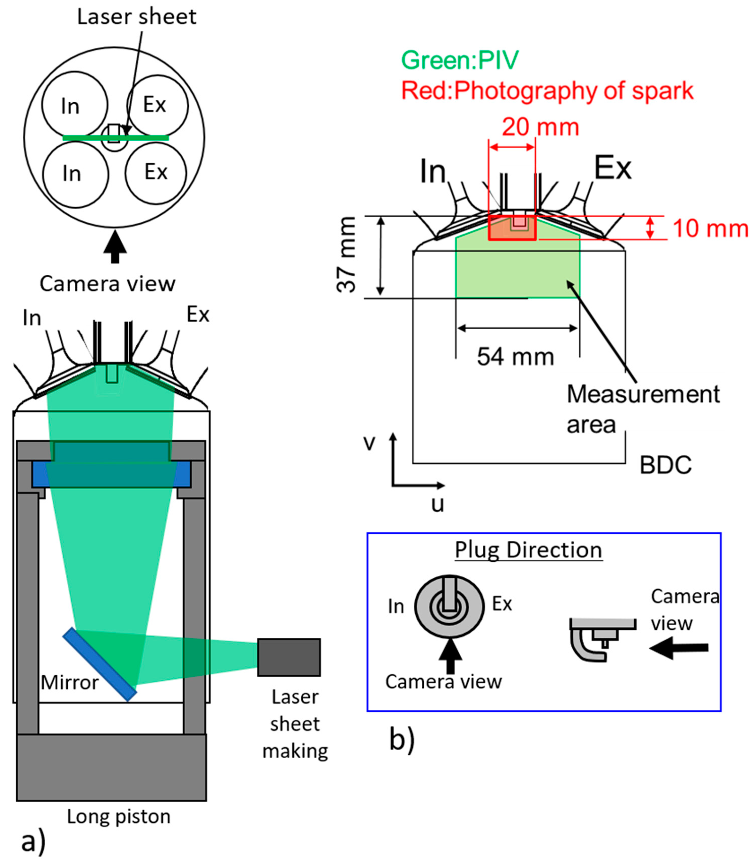
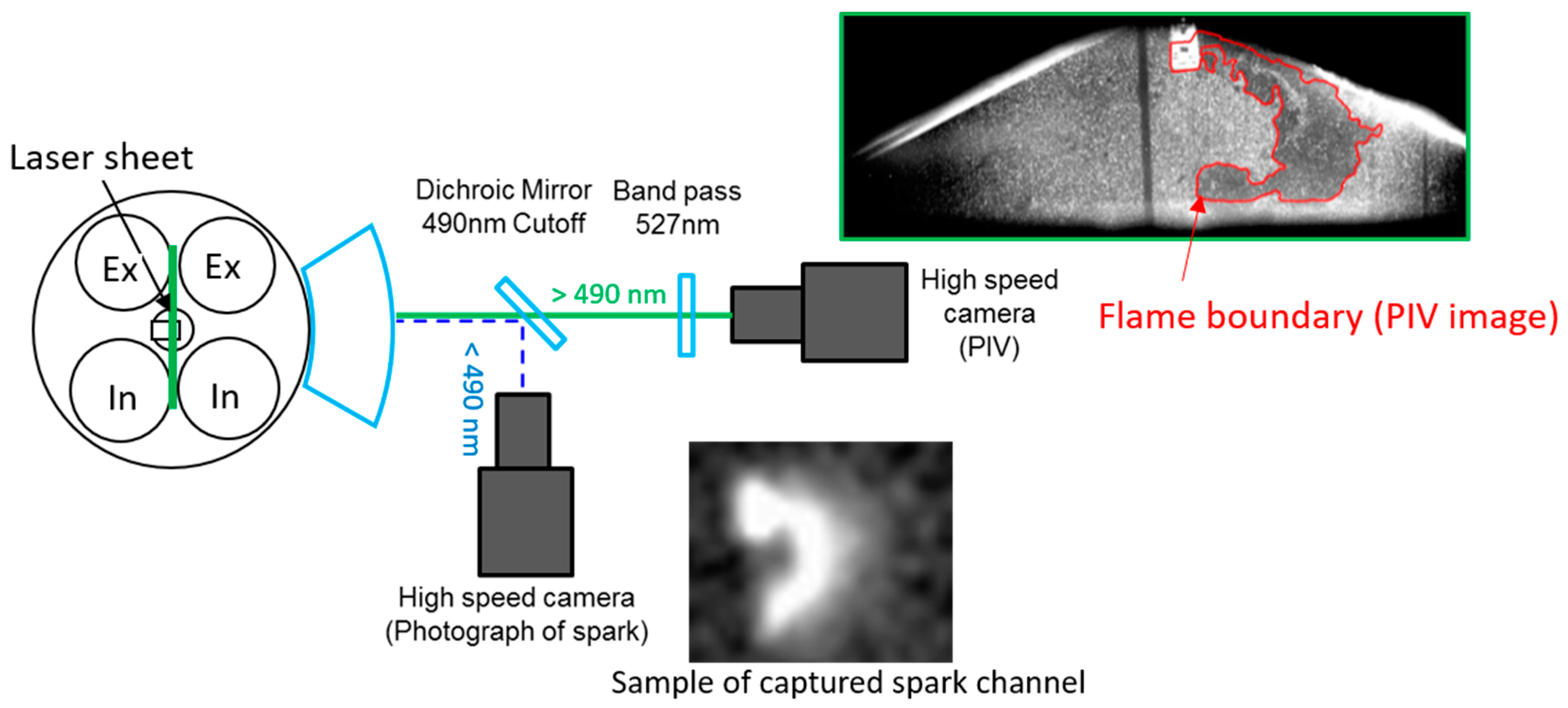
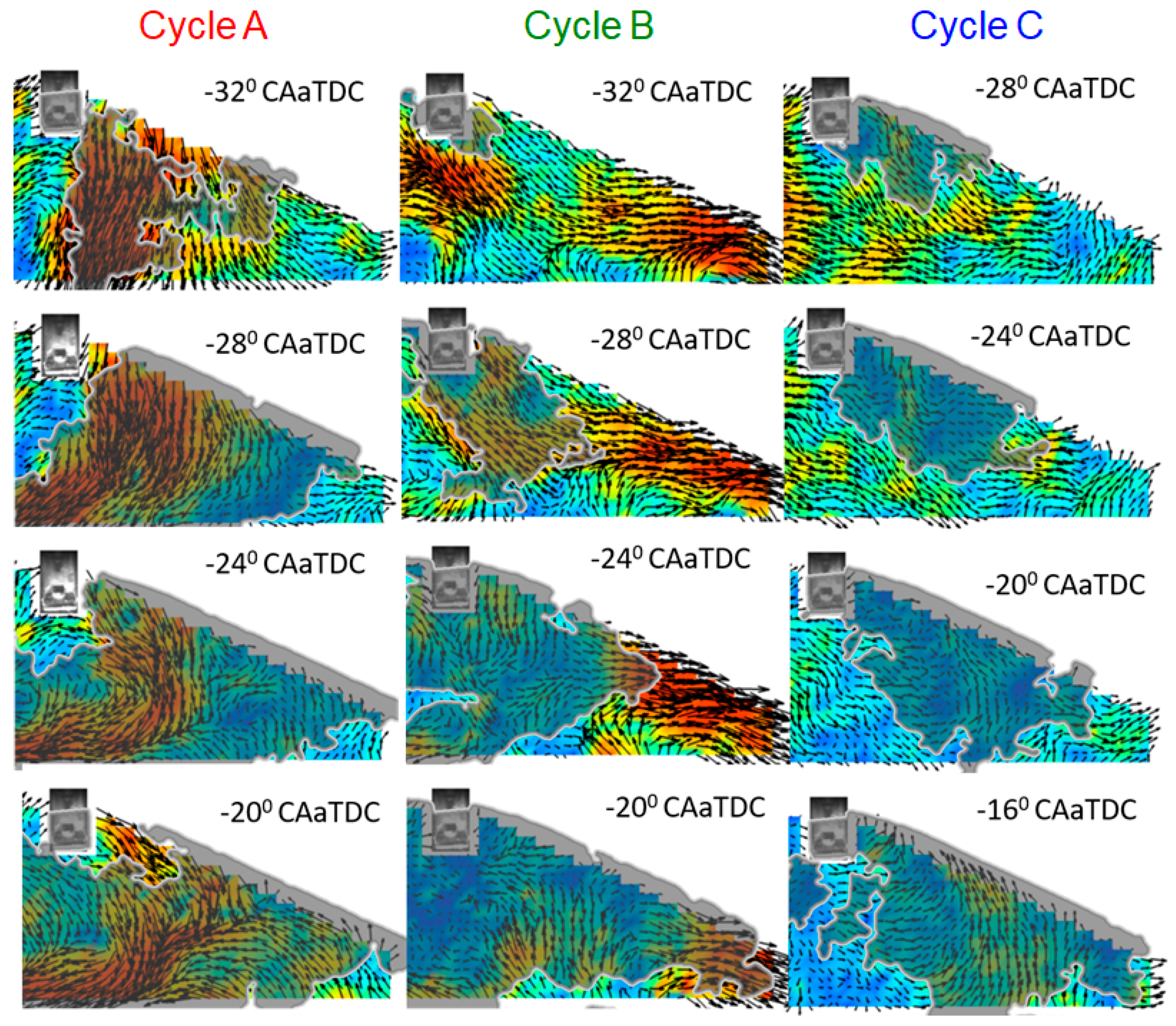
This relationship of the spark, in-cylinder flow-field, and flame kernel is observed inside an operating engine condition of a single-cylinder optical spark ignition engine. Table 1 summarizes the specification of this engine and the selected operating conditions. The engine capacity is 500 cm3 with a bore of 86 mm and stroke of 86 mm and has a compression ratio of 10.4. The top of the piston (54 mm diameter) and the pent-roof liner is replaced by a quartz window to provide an optical access into the combustion chamber of the engine, as shown in Figure 1a. Reflection from a 45° mirror placed in the hollow extended-piston provides an optical-access path for the laser sheet for the observation of the pent-roof area in the vertical plane, which is the desired configuration for this study. This optical view of the vertical plane in the pent-roof via the pent-roof liner windows is also used for simultaneous high-speed spark imaging, which will be described in detail in the following section. The experiments were carried out with the engine operating at two different speeds, 1200 rpm and 1700 rpm in order to generate different magnitudes of flow-field near the spark plug. The engine operated with a port fuel injection and an absolute intake pressure of 60 kPa; the air fuel ratio (A/F) was kept at slightly lean A/F of 18. The spark timing was set at −40° Crank-Angle after Top Dead Center (CA aTDC). In-cylinder pressures were monitored and recorded using a Kistler pressure transducer and the engine was fired continuously during the PIV/spark capturing process. Nineteen cycles were captured for each condition.

2.2. High-Speed PIV

The high-speed combustion PIV (HS-PIV) set up used in this study is the same as the one described in detail in a previous study [17]. The PIV signal of the pent-roof area is provided by inserting an 527 nm Nd:YLF laser sheet via a piston top quartz window using the reflection off the 45° mirror placed in the middle of the extended piston, as shown in Figure 1. Figure 1b displays the schematics of the measurement area, which contains an illustration of the spark plug in both top-view (left) and front-view (right). The measurement area is 37 mm × 54 mm, in which the spark-plug and its surrounding region is placed in the middle and the spark plug is orientated such that the camera view of the spark-gap is un-obstructed. Moreover, the ground electrodes are setup perpendicular to the tumble flow that has been observed previously in the same engine [17]. This ensures the spark will interact with the tumble flow without any obstruction. The PIV images were captured using a high-speed camera at 1280 × 800 resolution and a PIV time resolution of 1° CA and 2° CA corresponds to when the engine operates at 1200 rpm and 1700 rpm, respectively. For a higher resolution, a 150 mm macro lens was equipped to the camera.
While other PIV works under combustion conditioned has used liquid seeds [18,19], the PIV details are lost in the burned gas region as the seeds evaporated under high temperature. To retain the measurability of the flow field throughout the cycle in both burned and unburned region, burning resistant solid tracing particles SiO2 at various sizes were used, similar to a previous study in the same engine [17]. This is in contrast with when liquid particles were used [18,20] which causes the PIV details to be lost in the burned gas region via seed evaporation. The seeding particles were introduced into the intake air flow upstream of the intake system of the optical engine to ensure the homogeneous mixing and trace to the intake air motion. The seeding amount was adjusted for the best signal quality. Figure 2 (top left) displays a sample result image during the combustion period of the cycle. A 527 nm bandpass filter was placed just in front of the camera lens to isolate PIV signal from other interferences and a beam splitter was used to divert part of the view into the pent-roof for simultaneous spark imaging. PIV data was captured for 19 consecutive fired cycles. Additional details on the setup when simultaneous spark imaging was involved will be discussed more in a later section detailing the high-speed spark imaging.

2.3. High-Speed Flame Tomography

High-speed flame tomography imaging on the same laser plane can also be captured simultaneously with high-speed (HS)-PIV. This setup allows the flow and flame data to be analyzed and deduced from the same dataset, which essentially means that it eliminates potential errors as a result of misalignment, timing delays, or line-of-sight integration. This drastically improves the accuracy of the observed interactions between flow and flame. As seen in our previous work [17], the burned and unburned region can effectively be distinguished and identified in the PIV image by intensity gradient from the seed density, and hence, the planar flame front can be imaged. Advantageously, suitable seeds and seeding methods will still allow the PIV data in both the burned and unburned region to be measured.
In our works, the special in-house developed seed mixture, seeding procedures, and optimized laser fluence enables this simultaneous high-speed PIV and flame tomography. The PIV image is put through an in-house developed algorithm to determine the flame-front boundary (a sample is also shown in Figure 2). Each of the presented images in this paper will contain the flame boundaries and processed PIV flow-field results.

2.4. Spark High-Speed Imaging

To accomplish the goal set out in this investigation, PIV and flame imaging was carried out simultaneously with high speed spark imaging. As previously described, the PIV and flame data were captured in one dataset using one camera, and hence, the spark can be imaged using another camera. As illustrated in Figure 2, the two cameras for these diagnostics were positioned perpendicular to each other with the PIV/flame camera directly in-line with the pent-roof window. The light emissions from the combustion chamber through the pent-roof side window was split by a 45° dichroic mirror with a cut-off at 490 nm and then captured by the cameras. The dichroic mirror was orientated such that light above the cut-off of 490 nm was captured by the PIV/flame camera, whereas the signal below 490 nm was used for imaging the spark. This was due to the fact that the signal for PIV/flame was mainly the scattering of the laser light at 527 nm, while the spark emission was broadband with strong UV emissions. Moreover, this split also separated the interference of the laser signal from the high-speed spark imaging data. To be able to focus on the spark tip location for the spark imaging, a 200 mm macro lens was used together with 35 mm extension tubes. For the spark imaging, the area of interest was 20 × 10 mm around the spark tip. The camera was capturing at 50,000 frames per second to ensure all the spark movement was captured. It is also worth noting that the spark plug was installed in such a way that the J plug was behind the line of sight for the cameras, as this ensured the spark was not blocked. The spark plug used in this case was a small-tip iridium performance spark plug. The dwell time was around 3 ms, which translated to roughly 50 mJ ignition energy.

3. Results and Discussions

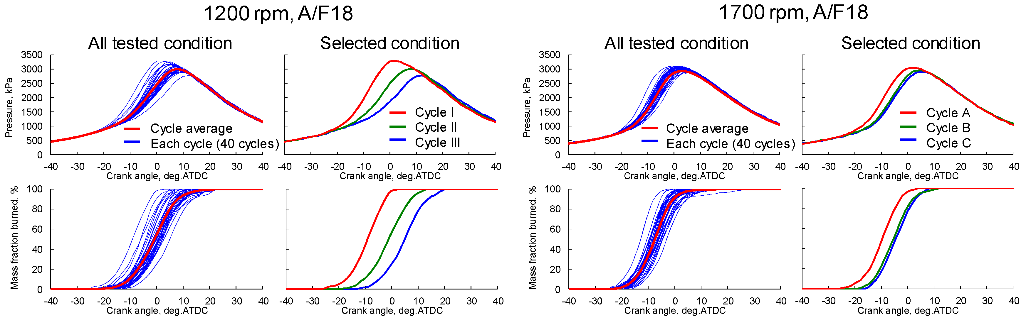
3.1. In-Cylinder Pressure and Mass Burned Fractions

Figure 3 displays the in-cylinder pressure and mass fraction burned (MFB) of the two tested operating conditions, 1200 rpm—A/F18 and 1700 rpm—A/F18 for all 40 tested cycles. The 1700 rpm case displays a shorter ignition delay and a shorter combustion duration. Moreover, the spread of both the pressure and MFB suggests that the combustion event is a lot more stable at 1700 rpm. For the analysis and discussion of the optical diagnostics results, three representative cycles were selected. These chosen cycles are the ones with highest, average, and lowest CA50, and hence, the observation of the flow-spark-flame interaction from optical diagnostics for them can provide clues to the cyclic variations. Images of the optical diagnostics will focus on the ignition period—just before the spark until the appearance of the early flame kernel.

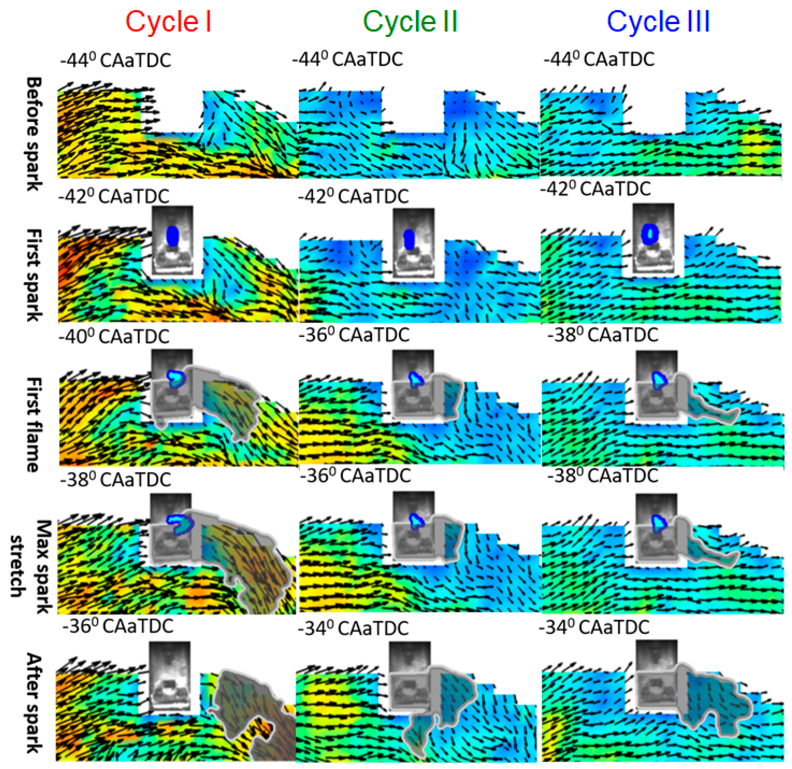
3.2. Operating Conditions 1200 rpm—A/F18

Figure 4 displays the images of combined in-cylinder flow from high resolution PIV and spark development from high-speed spark imaging near the spark plug. The blue area between the spark gap indicates the spark discharge path obtained from the spark high-speed imaging. The gray area indicates the burned area obtained from high-speed flame tomography. The earliest burning cycle, cycle I, is on the left-hand side, the average cycle, cycle II, is in the middle, and cycle III, the one with the longest ignition delay, is on the left of the figure. Cycle I also has a shorter combustion duration compared to cycle II and III. First, the in-cylinder flows of all the cycles appear to move clock-wise, from the intake valves to the exhaust valves which is the general tumble direction for this engine. For all cases, there exists a bulk flow perpendicular across the spark plug. It is quite noticeable that the earliest burning case has the fastest flow across the spark plug. Cycle III, however, only has a slightly slower flow across the plug compared to cycle II.
Regarding the spark behavior, there is a general spark movement with the in-cylinder flow across the spark plug for all cycles. The spark also displays a stretching behavior observed in other work. For the earliest burning cycle I, with the strongest flow, a largest spark stretch is also observed. In fact, a break in the spark channel can also be seen when the spark is at its maximum stretch. However, for the two other cycles, the difference is not very noticeable. Hence, in order to get more details about the relationship between the flow and spark behavior, not only for cycle II and III but also for cycle I, we measured and compared the flow speed across the plug with the stretch distance. Figure 5 displays this plot. For the flow speed across the plug, velocity at a representative point is used. This chosen point is 1 mm away from the left side of the spark plug (before the flow crosses the plug), in-line with the spark gap. In particular for this study, only the horizontal velocity at the point will be considered. Furthermore, the time for the velocity to be considered is the instant just before the first spark. An illustration of the location of this point with regard to the spark plug is shown on the plot. Also, in the illustration is the measurement method to determine the spark stretch distance, which is the distance between the first spark discharge and the maximum stretch of this first discharge before the spark channel is broken off. The plot confirms the visual observation of the data, with cycle I having the longest stretch and flow followed by cycle II and then III. Hence, a trend of faster flow speed, longer spark stretch, and shorter ignition delay can be deduced from this data. It also appears that the length of this stretch is somewhat proportional to the strength of the flow.
While there is a trend for the spark stretch, flow speed, and ignition delay, a slightly faster combustion duration in cycle I in comparison to cycle II and III will require additional information of the flame for a better understanding, due to the fact that the combustion duration of cycle II and III are very similar despite the difference in spark stretch and flow speed. Figure 6 displays images of flame development of these three cycles. The flames in these three cycles all develop toward the exhaust-valve side, which is with the direction of the bulk flow and the flow across the spark plug. Hence, it is reasonable to say that the direction of early flame kernel development is dependent on the flow direction across the spark plug. For all cases, the kernel appears while the spark channel is still presented. As the cycle I spark channel stretches much further than other cycles, the kernel also has extended much further with the flow at the point when the spark breaks and disappears. However, this effect is also due to the stronger overall tumble flow. As the flame develops, the kernel grows and continue to follow the bulk tumble flow direction. The flame also follows big vortices created by the flow and does not appear to be able to grow against the flow (as pointed out on the images with white arrows). Moreover, it is quite interesting that the growth of the flame also enhances the existing flow. Overall, it appears that the combustion duration is driven by the overall bulk flow strength rather than just the spark and flow near the spark region.

3.3. Operating Conditions 1700 rpm—A/F18

Figure 7 displays the PIV and spark images at the near spark region of three selected cycles at 1700 rpm. Similar to Figure 4 of the 1200 rpm condition, these three chosen cycles have the earliest, average, and latest start of combustion; they will be referred to as cycle A, B, and C, respectively. First impression shows that the general strength of the flow is much higher than at 1200 rpm, as expected from the higher piston speed at 1700 rpm. The general flow direction still goes across the spark plug from intake to exhaust, which is the same in both operating conditions. At the beginning of the spark event, there is a flow across the spark plug for all cycles, however, it is quite weak in cycle B. It is also clearer in the 1700 rpm image that after the flow crosses the plug, it diminishes significantly.
For cycle A, the strong flow has a strong effect on the spark channel. The channel stretches out quite a bit, comparable to the cycle I of 1200 rpm condition. However, unlike cycle I, the spark channel in cycle A actually breaks off and restrikes close to the end of the spark event. It is likely that the stronger flow in this case overcomes the ignition energy required to sustain the spark channel. These breaks in the spark channel will affect the combustion event negatively as it momentarily stops the supply of energy to grow the flame kernels [11]. As shown on the flow speed versus spark stretch in Figure 8, higher flow speed leads to longer spark stretch. Cycle C displays a somewhat longer stretch compared to cycle B, which can be explained by the lower flow speed near the spark plug. However, the proportion of this relationship in this case is not similar to that of the 1200 rpm condition. This is understandable, as the flow that will affect the stretch behavior of the spark cannot be completely represented two-dimensionally. Hence, when looking at the spark stretch distance, the velocity of the flow should be used only for qualitative information.
Despite having a longer spark stretch, cycle C has a slower start for the combustion compared to cycle B. However, the difference between the ignition delay of these two cycles is very small. Upon closer inspection, at the start of the flame kernel formation, the flow near the spark plug where the flame will develop is weaker in cycle C. This might negate the effect of a small spark stretch advantage. Interestingly, all three cycles have very similar combustion duration. As shown in Figure 9, the flames in all cycles develop toward the intake side, following the tumble bulk flow. While they all have different shapes and grow paths, the overall flow condition seems to be somewhat similar. This could be why the combustion duration is the same across the investigated cycles. This further suggests that it is the bulk flow in the combustion chamber that will influence the combustion duration, while the spark stretch and flow near spark plug will influence the start of the combustion.

4. Conclusions

Simultaneous high-speed PIV, flame tomography, and high-speed spark imaging is applied in an optical port-injected gasoline engine at two different operating conditions: 1200 rpm—A/F18 and 1700 rpm—A/F18. A dichroic mirror splits the signal to 2 cameras, with one setup for PIV and flame imaging, while the other is dedicated to high-speed spark imaging. The deduced results of the flow field, burned region, and spark imaging is combined and analyzed to understand the interaction between in-cylinder flow, spark behavior, flame development, and combustion performance. The following observations are made.
Higher flow velocity across the spark plug will result in a longer spark stretch distance. However, with a given ignition energy, the spark channel can only handle a certain flow speed limit before it breaks off and restrikes as the spark gap occurs.
A longer spark stretch and higher flow surrounding the spark plug (both sides, with and against the flow) shorten the ignition delay and allow an earlier start of combustion and flame kernel formation.
The flame will develop with the bulk in-cylinder flow and will follow the flow. It does not grow against the flow and will also enhance the existing flow in the same direction with its growth.
The combustion duration does not depend much on the spark stretch but mostly on the in-cylinder flow in the region of the combustion chamber where it is developing in.

Author Contributions

Conceptualization, Y.I.; methodology, F.T. and M.K.L.; software, M.K.L.; validation, M.K.L.; formal analysis, F.T. and M.K.L.; investigation, F.T.; resources, Y.I.; data curation, F.T.; writing—original draft preparation, M.K.L; writing—review and editing, A.N.; visualization, M.K.L.; supervision, Y.I.; project administration, A.N.

Funding

This research received no external funding.

Conflicts of Interest

The authors declare no conflict of interest.

References

  1. Le Coz, J. Cycle-to-Cycle Correlations between Flow Field and Combustion Initiation in an S.I. Engine. SAE Trans. 1992, 101, 954–966. [Google Scholar]
  2. Li, Y.; Zhao, H.; Ma, T. Flow optimization and fuel stratification for the stratified fuel spark ignition engine. Int. J. Engine Res. 2004, 5, 401–423. [Google Scholar] [CrossRef]
  3. Aleiferis, P.G.; Taylor, A.M.K.P.; Ishii, K.; Urata, Y. The nature of early flame development in a lean-burn stratified-charge spark ignition engine. Combust. Flame 2004, 136, 283–302. [Google Scholar] [CrossRef]
  4. Le, M.K.; Furui, T.; Nishiyama, A.; Ikeda, Y. The Interaction of Flow-Field and Turbulence on Flame Development using High-Speed Combustion PIV: High temporal and spatial resolved analysis of flame propagation and flame structure in a realistic combustion engine environment. In Proceedings of the 9th International Conference of Modeling and Diagnostics for Advanced Engine System (COMODIA 2017), Okayama, Japan, 25–28 July 2017. [Google Scholar]
  5. Becker, H.; Monkhouse, P.B.; Wolfrum, J. Investigation of extinction in unsteady flames in turbulent combustion by 2D-LIF of OH radials and flamelet analysis. Symp. Combust. 1990, 23, 817–823. [Google Scholar] [CrossRef]
  6. Peters, N. Local Quenching Due to Flame Stretch and Non-Premixed Turbulent Combustion. Combust. Sci. Tech. 1983, 30, 1–17. [Google Scholar] [CrossRef]
  7. Ombrello, T.; Won, S.H.; Ju, Y.; Williams, S. Flame propagation enhancement by plasma excitation of oxygen. Part I: Effects O3. Combust. Flame 2010, 157, 1906–1915. [Google Scholar] [CrossRef]
  8. Wolk, B.; DeFilippo, A.; Chen, J.Y.; Dibble, R.; Nishiyama, A.; Ikeda, Y. Enhancement of flame development by microwave-assisted spark ignition in constant volume combustion chamber. Combust. Flame 2013, 160, 1225–1234. [Google Scholar] [CrossRef]
  9. Shiraishi, T.; Urushihara, T.; Gundersen, M.A. A trial of ignition innovation of gasoline engine by nanosecond pulsed low temperature plasma ignition. J. Phys. Appl. Phys. 2009, 42, 1–12. [Google Scholar] [CrossRef]
  10. Kim, H.H.; Takashima, K.; Katsura, S.; Mizuno, A. Low-temperature NOx reduction processes using combined systems of pulsed corona discharge and catalysts. J. Phys. Appl. Phys. 2001, 34, 604–613. [Google Scholar] [CrossRef]
  11. Kim, H.J.; Won, S.H.; Santner, J.; Chen, Z.; Ju, Y. Measurements of the critical initiation radius and unsteady propagation of n-decane/air premixed flames. Proc. Combust. Inst. 2013, 34, 929–936. [Google Scholar] [CrossRef]
  12. Herweg, R.; Maly, R. A Fundamental Model for Flame Kernel Formation in S.I. Engines. SAE Trans. 1992, 101, 1947–1976. [Google Scholar]
  13. Smith, J.D.; Sick, V. A Multi-Variable High-Speed Imaging Study of Ignition Instabilities in a Spray-Guided Direct-Injected Spark-Ignition Engine. SAE Tech. Pap. 2006, 2006-01-1264. [Google Scholar] [CrossRef]
  14. Nishio, N.; Aochi, T.; Yokoo, N.; Nakata, K.; Abe, Y.; Hanashi, K. Design of a High Ignitability Spark Plug with a Flow Guide Plate. SAE Tech. Pap. 2015, 2015-01-0780. [Google Scholar] [CrossRef]
  15. Pischinger, S. Effects of Spark Plug Design Parameters on Ignition and Flame Development in an SI-Engine. Ph.D. Thesis, Massachusetts Institute of Technology, Cambridge, MA, USA, 1989. [Google Scholar]
  16. Suzuki, K.; Uehara, K.; Murase, E.; Nogawa, S. Ignition System for Gasoline Engines. In Proceedings of the 3rd International Conference, Berlin, Germany, 3–4 November 2016. [Google Scholar]
  17. Le, M.K.; Furui, T.; Nishiyama, A.; Ikeda, Y. Application of High-Speed PIV Diagnostics for Simultaneous Investigation of Flow Field and Spark Ignited Flame inside an Optical SI Engine. SAE Tech. Pap. 2017, 2017-01-0656. [Google Scholar] [CrossRef]
  18. Mounaïm-Rousselle, C.; Landry, L.; Halter, F.; Foucher, F. Experimental characteristics of turbulent premixed flame in a boosted spark-ignition engine. Proc. Comb. Inst. 2013, 34, 2941–2949. [Google Scholar] [CrossRef]
  19. Peterson, B.; Reuss, D.L.; Sick, V. High-speed imaging analysis of misfires in a spray-guided direct injection engine. Proc. Comb. Inst. 2011, 33, 3089–3096. [Google Scholar] [CrossRef]
  20. Aleiferis, P.G.; Behringer, M.K. Flame front analysis of ethanol, butanol, iso-octane and gasoline in a spark-ignition engine using laser tomography and integral length scale measurement. Combust. Flame 2015, 162, 4371–4674. [Google Scholar] [CrossRef]
Figure 1. (a) Optical engine and PIV set up, (b) PIV measurement area, and position of the laser sheet with respect to the cylinder and plug direction with respect to the camera.
Applsci 09 01545 g001
Figure 2. Simultaneous setup for PIV/flame imaging and high-speed spark imaging, together with their sample raw images.
Applsci 09 01545 g002
Figure 3. In-cylinder pressure traces (top) and mass fraction burnt (bottom) of all tested cases and selected cases for the two operating conditions (1200 rpm and 1700 rpm).
Applsci 09 01545 g003
Figure 4. Near spark combined PIV-flame-spark images of three selected cycles (I, II, and III) at 1200 rpm condition.
Applsci 09 01545 g004
Figure 5. Flow speed and spark stretch relationship at 1200 rpm operating condition. Also shown is an illustration for the calculation of stretch distance and flow speed determination.
Applsci 09 01545 g005
Figure 6. PIV-flame-development images after initial kernel development of three selected cycles (I, II, and III) at 1200 rpm condition.
Applsci 09 01545 g006
Figure 7. Near spark combined PIV-flame-spark images of three selected cycles (A, B, and C) at 1700 rpm condition.
Applsci 09 01545 g007
Figure 8. Flow speed and spark stretch relationship of selected cycles at 1700 rpm condition.
Applsci 09 01545 g008
Figure 9. PIV-flame-development images after initial kernel development of three selected cycles (A, B, and C) at 1700 rpm condition.
Applsci 09 01545 g009
Table 1. Engine Specifications and operating conditions.
Engine Type4 Stroke, Single Cylinder, port fuel injection (PFI)
Displacement500 cc
Bore × stroke86 × 86 mm
Compression ratio10.4
Number of valvesIntake: 2, Exhaust: 2
Engine speed1200 and 1700 rpm
Intake pressure60 kPa
Air fuel ratio (A/F)18
Spark timing40 deg. before top dead center (BTDC)

