A Telepresence System for Therapist-in-the-Loop Training for Elbow Joint Rehabilitation


1
State Key Laboratory of Robotics and System, Harbin Institute of Technology, Harbin 150001, China
2
Tianjin Key Laboratory for Control Theory & Application in Complicated Systems and Biomedical Robot Laboratory, School of Electrical and Electronic Engineering, Tianjin University of Technology, Binshui Xidao 391, Tianjin 300384, China
3
Department of Intelligent Mechanical Systems Engineering, Kagawa University, 2217-20 Hayashi-cho, Takamatsu 761-0396, Japan
*
Authors to whom correspondence should be addressed.
Appl. Sci. 2019, 9(8), 1710; https://0-doi-org.brum.beds.ac.uk/10.3390/app9081710
Submission received: 17 March 2019
/
Revised: 18 April 2019
/
Accepted: 22 April 2019
/
Published: 25 April 2019
(This article belongs to the Special Issue Recent Advance and Future Trends in Rehabilitation and Nursing-Care Robots)
Abstract
:This paper proposes a new robotic rehabilitation training platform that is motivated by the requirement for adjusting the training strategy and intensity in a patient-specific manner. The platform is implemented for tele-rehabilitation and is comprised of a haptic device operated by therapists, a lightweight exoskeleton worn by patients and a visually shared model. Through the visually shared model, the motion of the therapist and patient are measured and mapped to the motion of the corresponding object. Thus, the force generated by the therapist can be transferred to the patient for delivering training, while real-time force feedback with high transparency can be provided to the therapist so they know the amount of force being applied to patients in real time. In particular, both assistive therapy in the early stages and resistive therapy in the later stages of stroke can be performed. The home-use exoskeleton device is specifically designed to be light-weight and compliant for safety. The patient-exoskeleton and therapist-haptic interaction performance is evaluated by observing the muscle activities and interaction force. Two volunteers were requested to imitate the process of the therapist-in-the-loop training to evaluate the proposed platform.
1. Introduction
Activities of daily living can be impacted by many events such as new or recurrent strokes, which can impair the motor control of the upper limbs. Stroke has also become a leading cause of severe long-term disability and stroke patients are predicted to increase by 4 million by 2030 in the USA [1]. Compared with manual therapy, robot-aided therapy has been certified as more effective and suitable for rehabilitation without fatigue for long-time therapy [2]. Many rehabilitation systems have been developed for performing the training and can be generally divided into endpoint types [3,4] and exoskeleton types [5,6]. Between them, endpoint types are more straightforward to adjust to accommodate different patients and attach to the distal end of patients’ limbs and they do not suffer from joint alignment problems [7]. The drawback is that end-effector type rehabilitation robots have to constrain the redundancy of the patient’s arm and this restriction limits the training in hand and wrist function. Contrarily, although exoskeleton devices have more complicated system dynamics and mechanical structure, they can provide the training and obtain the feedback for each joint independently. Moreover, some devices use cable mechanisms to transmit the power of motors mounted on the backboard to the corresponding joints and these devices are compact, lightweight and comfortable for patients [8,9,10].
In addition, some research has also proved that robotic therapy could be less effective than conventional manual therapy in some situations [11]. Rehabilitation robots need to adjust the training strategy and intensity to the specific requirements and abilities of different individuals. Some adaptive methods have been proposed for specific training. For instance, Pehlivan et al. designed a minimal assist-as-needed (mAAN) controller, which uses a model-based sensorless force estimation method to determine subject capability and provide required minimal assist-as-needed rehabilitation [12]. Huq et al. designed the partially observable Markov decision process (POMDP), which allows an automated rehabilitation system to autonomously adjust different exercise parameters according to each individual’s needs [13]. Artificial intelligence (AI) methods such as artificial neural networks [14] have also been employed for improving the intelligence when performing active assistance to a user’s affected arm. However, although these adaptive methods can improve the performance of training, the experience and knowledge of a skilled therapist can still not be matched well due to the lack of flexibility in tuning the control parameters compared to conventional therapy. Therefore, patient-specific training involving therapists can be adjusted to the training strategy and assistive/resistive therapeutic force fields for different individuals can be applied by the therapists, according to their abundant experience [15,16]. For instance, Atashzar et al. proposed two new frameworks which are haptics-enabled teleoperated supervised training and electromyography-based indirect supervised training for tuning the strategy and intensity of training in a patient-specific manner [15].
Because of the inconvenience of regularly attending rehabilitation centers, home-based tele-rehabilitation systems are likely to become a trend. However, the absence of the supervision of a skilled therapist will become an issue. Some researchers have applied a motion capture device, like Kinect developed by the company of Microsoft, to assist with guidance, correction, management and assessment of patients’ movements [17,18,19,20,21,22,23]. Brokaw et al. proposed a system with Kinect and a haptic device which can simulate the pressure the therapist applies to training [24]. However, the force feedback is absent in the majority of tele-rehabilitation systems. In this study, a therapist-in-the-loop training platform is proposed for elbow joint motor function recovery. The platform is used together with our previously developed muscle strength assessment system [24,25]. The assessment system allows therapists to assess the status of patients and adjust the training parameters of various training devices. The contribution of this paper is that with the therapist-in-the-loop platform, human therapists are capable of appropriately adjusting the training strategy and amount of kinesthetic guidance over the work session. In particular, both the assistive and resistive force generated by the therapist can be transferred into a patient with an exoskeleton device for delivering training. The exoskeleton for patients is safe to use with a specially designed torque limiter mechanism [26]. In particular, the use of virtual reality (VR) technology can provide goal-directed tasks with rewards and motivate the patient to undertake extended rehabilitation. Through the visually shared model, the motion of the therapist and patient are measured and mapped to the corresponding object’s motion. The force generated by the therapist can be transmitted to the patient for delivering training with an exoskeleton device, while real-time force feedback can be provided to a therapist with a haptic device to know the amount of force being applied to the patient.
This paper is organized as follows. The background and related research are introduced in Section 1. In Section 2, the schematic of the implemented training platform and the visually shared model are introduced. In particular, the 2-port network model is introduced for transparency between the master and slave sides of the proposed platform. In Section 3, the models for patient-exoskeleton interaction and therapist-haptic device interaction are given. The experiments and results are given in Section 4 including patient-exoskeleton, therapist-haptic device interaction, and a therapist-in-the-loop test. Lastly, the conclusion and future works are discussed.
2. System Overview
2.1. Schematic of the Implemented Training Platform
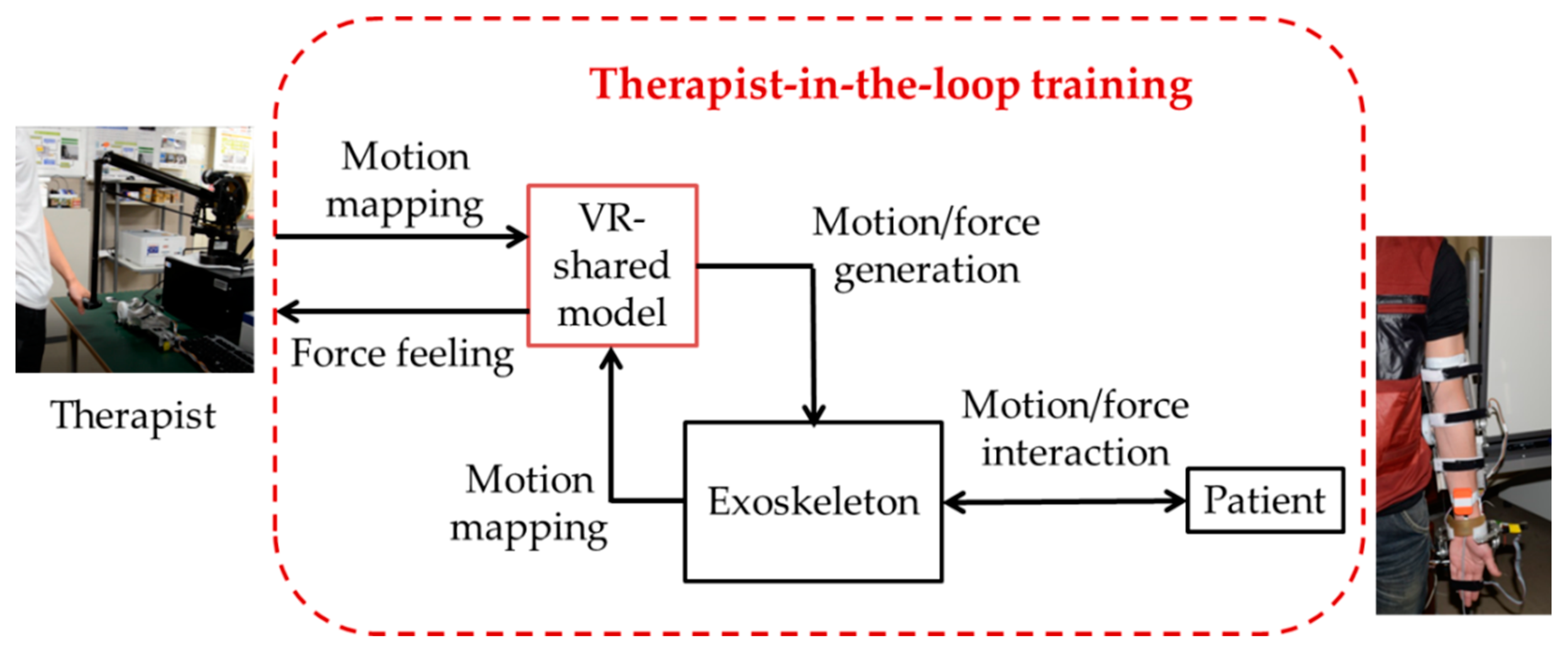
The schematic diagram of the therapist-in-the-loop rehabilitation training system for elbow joint motor function recovery is shown in Figure 1. The platform is motivated by the current challenge regarding the need for tuning the strategy and intensity of robotic rehabilitation systems in a patient-specific manner. It also enables therapists to share their time with several patients. The platform is actually used together with the muscle strength tele-assessment platform, which can record the activation level of skeleton muscles with surface electromyogram (sEMG) at home and predict the muscle strength with a prediction function derived from a musculoskeletal model [27]. The hardware of the system consists of a haptic device (Phantom Premium 3.0, 3D Systems, Rock Hill, SC, USA) on the therapist’s side, an exoskeleton device on the patient’s side, and a specially designed visually shared training model. The visual training model is rendered with Open Graphics Library (OpenGL, Khronos Group, Beaverton, OR, USA). On the therapist’s side, the motion of the therapist is measured and mapped to the corresponding object in the training model. Previously, we designed a coordinative motion-based training system for bilateral rehabilitation with an exoskeleton and haptic devices [28]. Different from that, in this study, the system is designed for patient-specific training, and the motion and force between therapist and patient are transmitted with a visually shared model. The therapist cooperates with the patient to achieve a goal-oriented task. There are also two phases: the online training phase and the regeneration phase. In the online training phase, the training intensity and strategy can be recorded when a therapist delivers the training. During the regeneration phase, the academic therapeutic experience can be regenerated. Therapy strategies may be adjusted between assistance and resistance according to patients’ experience and adjustment. The therapists’ motion will be regenerated with the exoskeleton device. The intensity is correlated with the selection of control parameters (such as the stiffness of the practical guidance) considered for delivering therapy.
2.2. Visually Shared Training Model
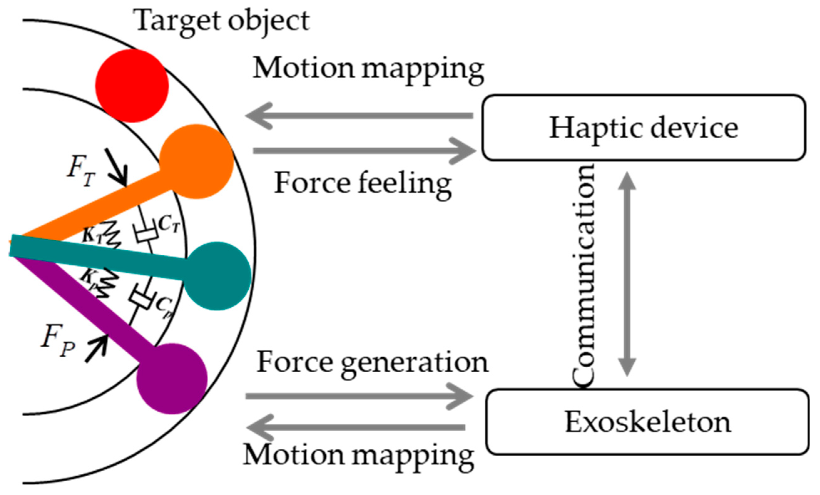
The visually shared training model shown in Figure 2 was proposed for elbow joint rehabilitation based on the neuro-rehabilitation theory that states that the brain has the ability to reorganize through sensory input, experience and learning [29]. The visually shared environment provides patients with goal-oriented tasks that enable them to use their decision-making abilities. The coefficients of springs ( and ) and dampers () shown in Figure 2 can be selected according to the predetermined muscle strength assessment system [27]. In particular, increasing the stiffness and viscosity in the model can relatively reduce the position-dependent and velocity-dependent error between the motion of the therapist and the one allowed for the patient [16]. Also, the patient is allowed to make errors in tracking the target object while performing motor tasks, which has been proved to be an essential factor for motor learning [30].
Through the visually shared model, the motion of the therapist and patient are measured and mapped to the orange and purple objects which correspond to the movement of the therapist and the patient’s elbow movements. The position of the green object is a position resulting from the two sets of spring and damper. The red target object represents the desired position the patient needs to reach. This position will change after the green object reaches it. In particular, the force generated by the therapist can be transferred to the patient for delivering training, while real-time force feedback can be provided to the therapist so they know the amount of force being applied to patients through two sets of mass-spring-damper models as shown in Equations (1) and (2):
where kT and kP represent the coefficient of elasticity on therapist and patient sides, respectively, and represent the viscosity coefficient on each side, θT and θp represent the change in the spring’s length, which is in accordance with the forearm flexion/extension angle of therapists and patients, and and represent the velocity of the spring’s deflection. The θT is calculated from the relative kinematics with the haptic device, and the θp is measured with an inertia sensor (MTx sensor, Xsens, Enschede, the Netherlands) mounted on the forearm [28]. Moreover, the additional merits of the proposed visually shared model for realizing and appropriately adjusting of training strategies and the amount of kinesthetic guidance provided over the session are summarized as follows: (1) when the patient needs assistance, the therapist can provide assisting force through the training model and the force can be generated by exoskeletons. It is also an assist-as-needed strategy, which was proven to be more effective. During the assistive training, the robot guides patients while assisting them towards the correct path; (2) during the supervision of the therapist, the therapist can also provide extra resistive force which is generated by exoskeletons with an impedance controller. In this case, the exoskeleton may dissipate parts of the energy generated by the patient to make the task more challenging; (3) the platform provides a high transparency with the model. Here, the master (patient) and slave (therapist) sides of the proposed platform can be represented by a 2-port network model which is distributed at both ends, and it is important to keep the transparency.
The relationship of these components in the 2-port model can be represented with a hybrid model [31], as shown in Equation (3):
where, FP represents the force exerted to patients with exoskeletons; vp is the velocity output of the patients’ forearm; fT represents the interaction force between the haptic device and therapist; and vT is the velocity of the haptic device. H is a defined hybrid matrix, which can be expressed as Equation (4) [32]:
where, Zin and Zout represent the impedances on the master side and slave side, and h12(s) and h21(s) represent the functions of the master and slave dynamics and the control parameters, respectively. H(s) represents a kinesthetic relationship between the patient and the therapist while building a relationship between force and velocity. In the ideal conditions, the hybrid matrix H(s) is given by Equation (5):
The transparency condition of the platform between the master side and slave side is defined as Equation (6) [33]:
where the ZP represents the generated impedance by the exoskeleton to patients and ZT is the impedance that the haptic device generated and added to therapists. When these values are equal, we say the system is transparent. Finally, real-time feedback with high transparency can be provided to make the therapist aware of the forces being applied on the patient’s forearm. The force information is beneficial to therapists to help decide on the sensorimotor needs of the patient.
3. Method and Materials
3.1. Model for Patient-Exoskeleton Interaction
The proposed platform allows a human therapist at the slave side to intuitively assist/resist the patient’s trajectories based on their therapeutic skills. Therefore, the exoskeleton devices should have the ability to adjust output impedance for generating both assistive and resistive forces. We previously designed an exoskeleton device on the elbow joint, and an improved impedance controller was implemented [34,35], as shown in Figure 3.
The mechanism schematic is shown in Figure 3. The force Fp(t) applied by the patient to the master device can be calculated by Equation (7),
where the θ1 is measured with the MTx sensor mounted on the forearm, which means an angle between the affected limb and horizontal plane and θ1 is equal to the θP in the visually shared model; θ is the angle between the forearm frame and a horizontal plane; k and d represent the spring and damping coefficient, respectively, because the exoskeleton follows the principle of the serial stiffness actuator (SEA) [36,37,38]. We can obtain the rotational velocity of the affected limb, which is given by Equation (8):
where, α1 and α2 is the rotational angle of the device and the angle of the passive rotational joint in the exoskeleton for avoiding the misalignment of elbow joint [7].
3.2. Model for Therapist-Haptic Device Interaction
During the therapy, the therapist tunes his/her reaction to generate a desirable therapeutic response based on the patient’s need via the visually shared model. The behaviour can result in either assisting or resisting the motion to patients. An impedance control where the robot is rendered as having mass, spring, and damper properties was used for the haptic device. The control formula is given by Equation (9)
where , , xd are the desired acceleration, velocity and position; , , xT are actual acceleration, velocity and position, respectively.
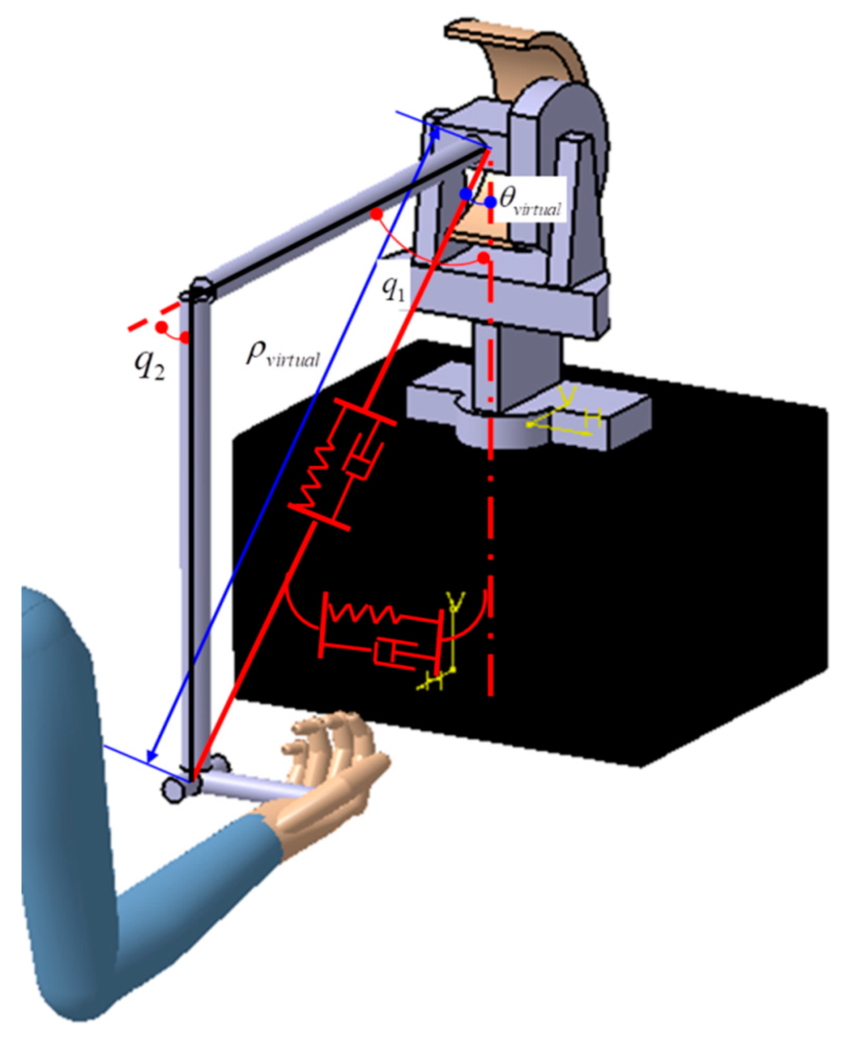
The device is operated in a two-dimensional space which is consistent with the visually shared training model. Therefore, the torque for two active joints can be calculated by Equation (10).
where, eρ, , and are the radial position error, radial velocity error, angular position error, and angular velocity error between the actual trajectory with the designed trajectory. Jpolar(q) is the Jacobian from the haptic device’s motor part to the handle, where and are the two generalized coordinates as shown in Figure 4.
4. Experiments and Results
4.1. Performance Evaluation for the Patient-Exoskeleton Interaction
The exoskeleton adopts a high geared mechanism for guaranteeing enough torque output with a lightweight design; however, the passive character of the actuator’s non-backdrivability limits the ability to generate variable impedance output. The non-backdrivability means that the mechanical system should have low impedance [39]. For our proposed therapist-in-the-loop platform, the actuation and control system should provide both robot-in-charge and patient-in-charge modes. When the patient can control some movements, the patient-in-charge mode is needed where the robot should not hinder the patient motion, but instead it should show near-zero impedance while assisting the user via the visually shared model. The near-zero impedance output is also a precondition for generating resistive force. Therefore, it is necessary to carry out an experiment to evaluate the near-zero impedance output of the control system.
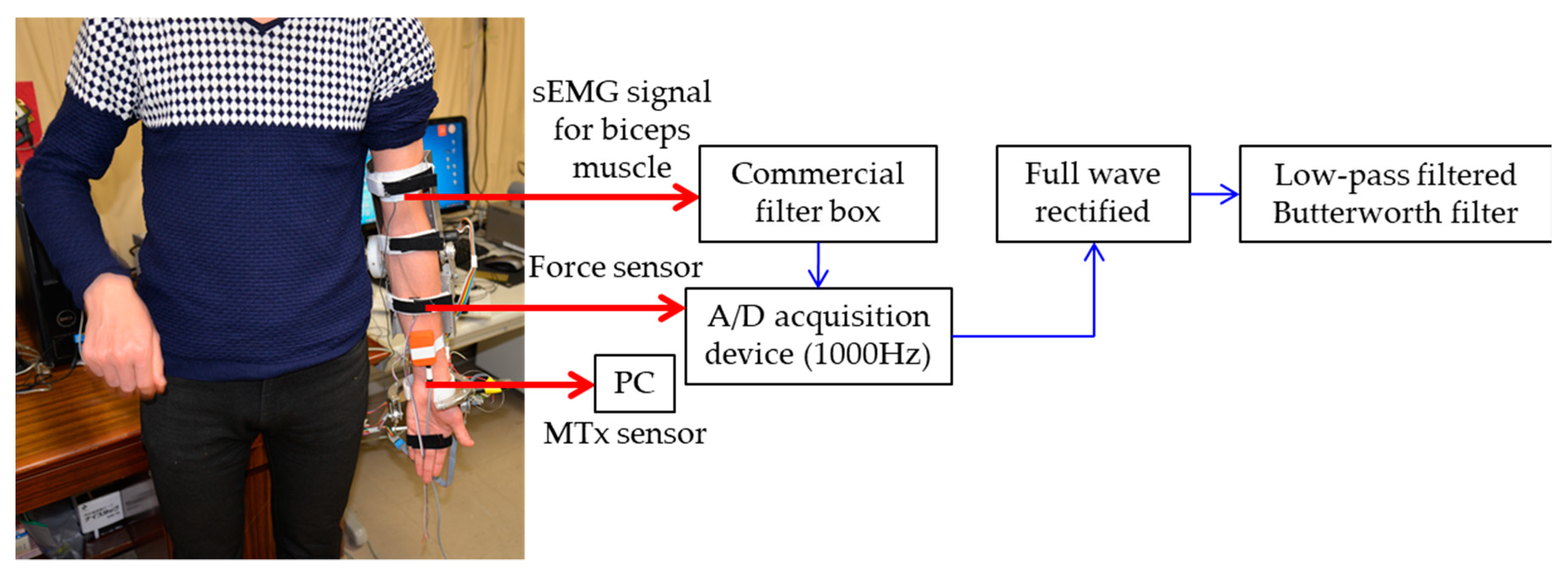
For the exoskeleton, a torque limiter mechanism was designed for the actuator; and by adjusting the clamp nut, the friction between the axle sleeve of the motor and the helical capstan shaft can be controlled [24]. In other words, we can release the clamp nut, so that the elbow motor will not provide the power to the robot frame. Two comparison experiments were carried out, and both muscle activities and the interactive force between forearm and device were used to evaluate the performance. In case one, the clamp nut was released, and the involved subject could freely flex his forearm. In case two, the clamp nut was screwed tightly. Thus, the control system will play a role in generating near-zero impedance, i.e., the exoskeleton can track the forearm motion freely. The subject also flexed his forearm as in case one. The muscle activities for biceps muscle were measured with a sEMG, because only the biceps muscle was involved for elbow flexion motion. The data acquisition and processing process are shown in Figure 5. The recorded sEMG signals were pre-processed by a commercial filter box (10–500 Hz band-pass, 60 Hz band-rejection, amplified 1000 times, Personal EMG, Oisaka Development Ltd., Fukushima, Japan) with differential amplification (gain: 1000) and common mode rejection (104 dB) at a sampling frequency of 3000 Hz and then sampled at 1000 Hz by a 16-bit A/D acquisition device (USB4716, 16-channel inputs, Advantech Co., Ltd., Taiwan). Other detailed information for signal acquisition can be found in our previous research [27]. Post-processed sEMG signals were then full wave rectified and low-pass filtered by a 1st order Butterworth filter with a cut-off frequency of 10 Hz to acquire the envelope, and the interaction force was measured with a force sensor (FS03, Honeywell, Morristown, NJ, USA) attached between the belt and sampled with the A/D board simultaneously. The MTx sensor measures the flexion angle of the forearm simultaneously.
The experimental result for case one is shown in Figure 6, where the biceps muscle activities and interaction force were recorded while the forearm flexed. The maximum value for the interaction force is 0.098 N, and the mean value for the sEMG signal is 0.0366 V. On the contrary, for case two, which is shown in Figure 7, the maximum value for the interaction force is 0.2127 N while the mean value for the sEMG signal is 0.0376 V. By comparing these two experiments, it can be seen that the control system performs well; the proposed impedance controller effectively solves the backdrivability problem.
4.2. Performance Evaluation for the Therapist-Haptic Device Interaction
Real-time feedback with high transparency can be provided to make the therapist aware of the forces being applied to the patient’s forearm through the haptic device. The performance when the therapist receives the force feedback should also be evaluated and stable feedback is a precondition for the high transparency. The sEMG that reflects the electrical activity produced by skeletal muscles is a convincing and direct method to evaluate the feedback.
The experimental process is illustrated in Figure 8, where the therapist was requested to do the elbow flexion and extension movement following the order. Also, a similar visual model without unnecessary parts, that is, just one beam which corresponds to the elbow motion was developed for reminding the volunteer of their position. Meanwhile, the volunteer should resist the force exerted by the haptic device and keep a steady speed. Only signals from biceps were recorded, and the method is similar to that introduced in Section 4.1. Here, the resulting force that is exerted by the haptic device is calculated with Equations (12) and (13), and only the angular position error was used with different as given in Table 1.
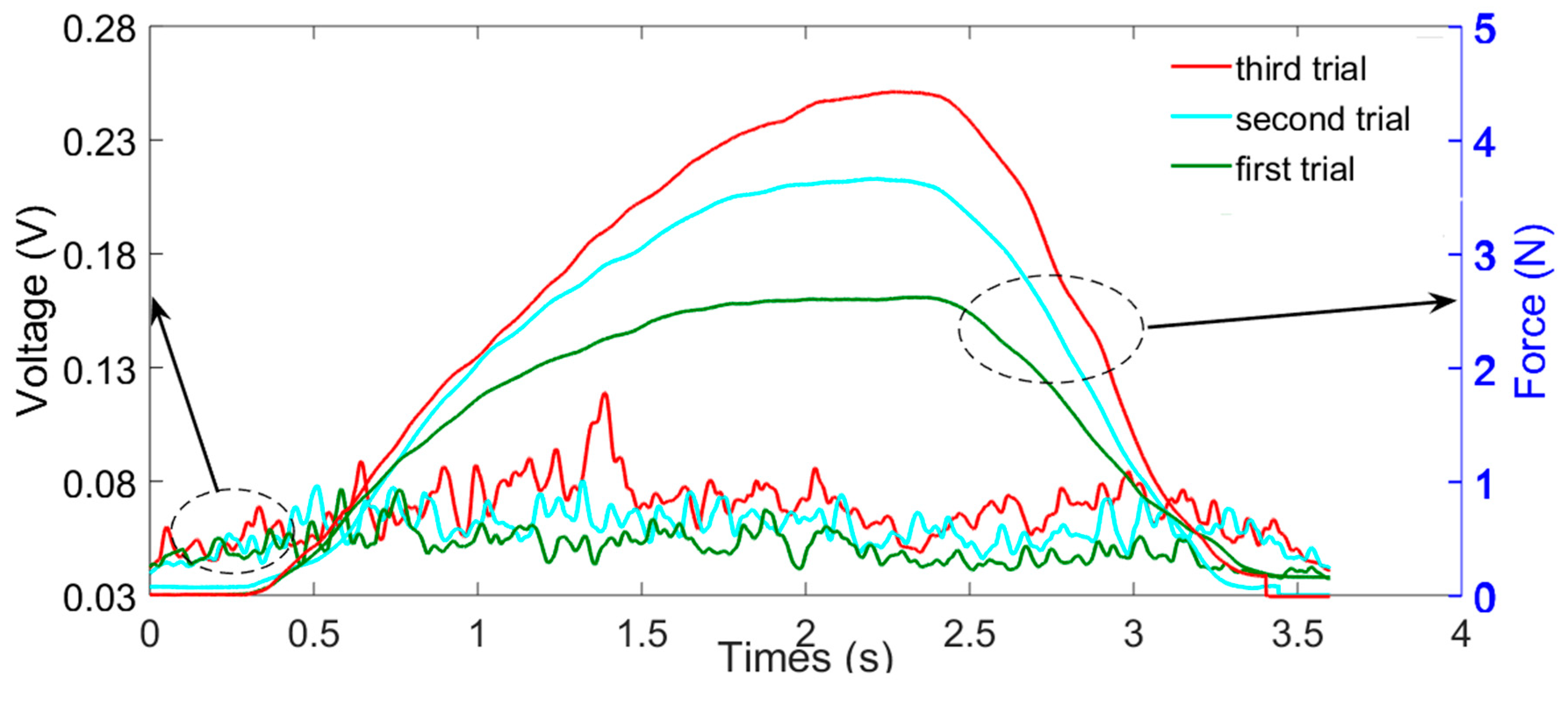
The experimental result for three trials with different is shown in Figure 9. It can be seen that the amplitude of the value was increased although a relatively small force was exerted by the haptic device.
4.3. Performance Evaluation for the Therapist-in-the-Loop Training
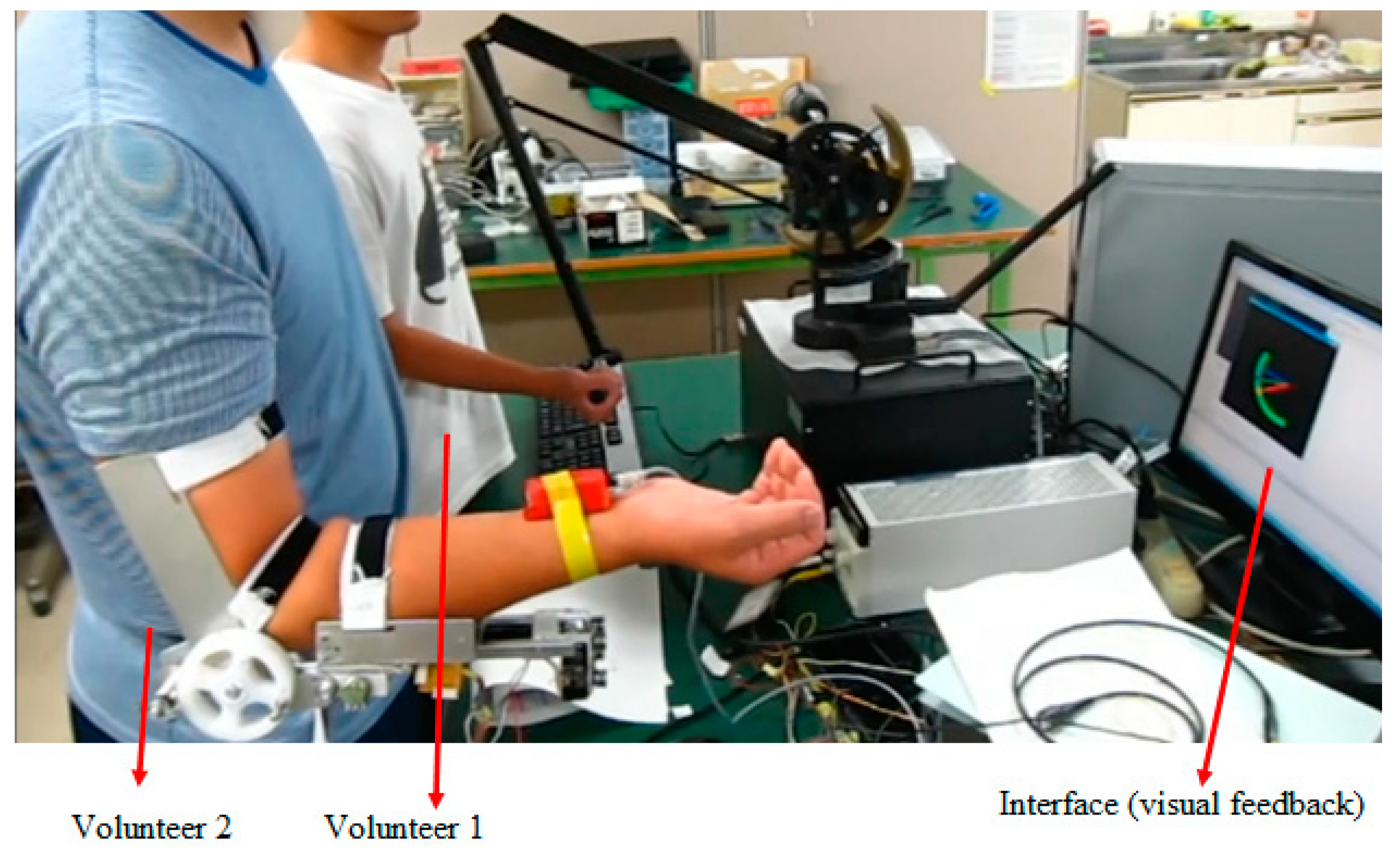
The experiment was performed at a local area network for evaluating the feasibility of the proposed platform as shown in Figure 10. The wrist mechanism was not installed during the experiment. Volunteer 1 plays the role of the therapist that operates the haptic device; while the volunteer 2 plays the role of the patient who wears the exoskeleton.
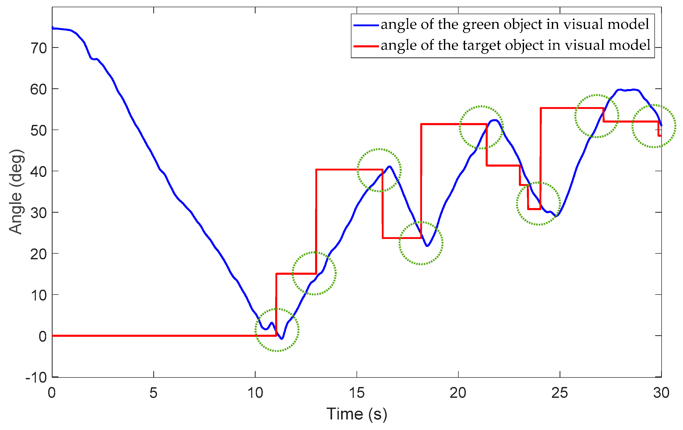
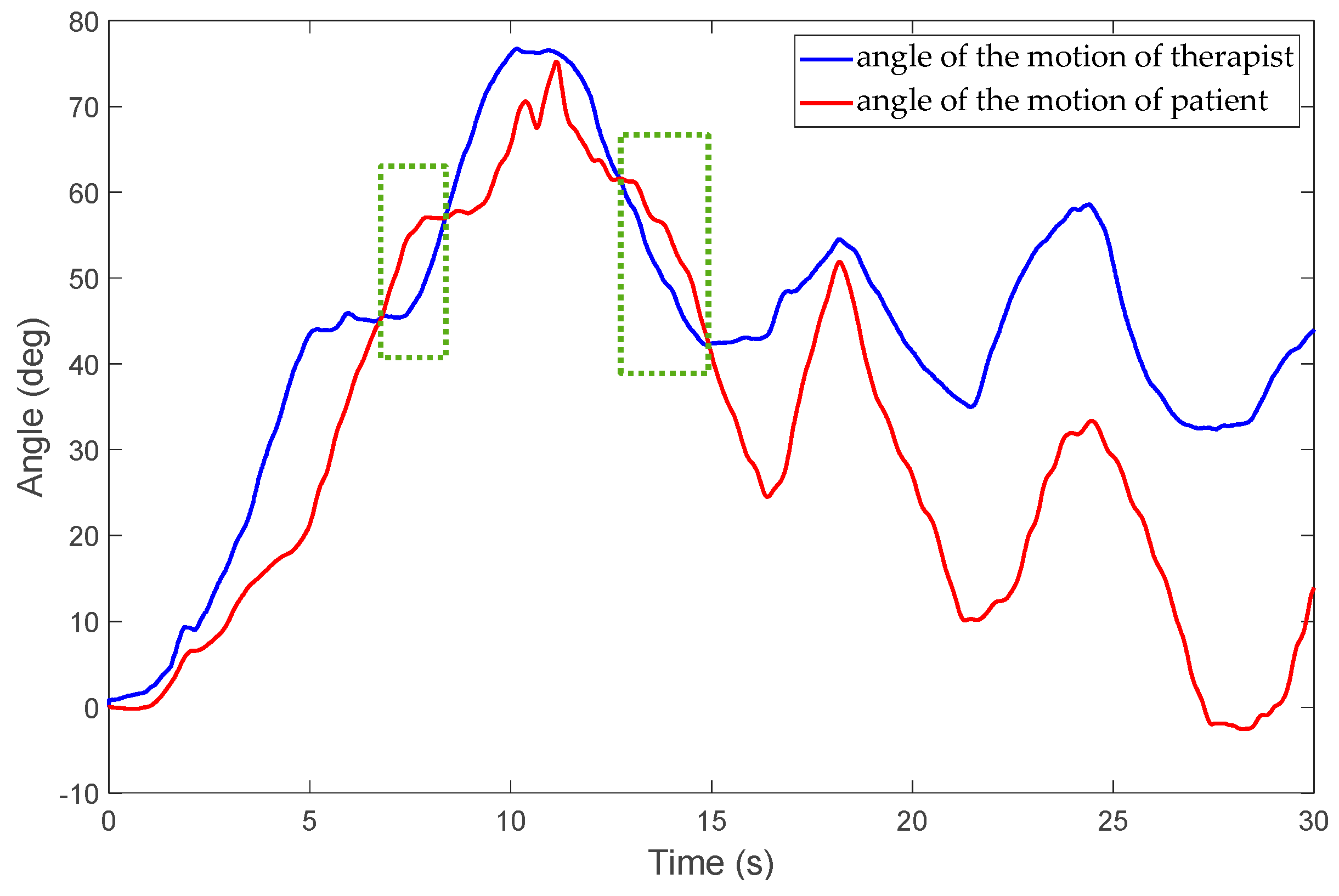
During the experiment, volunteer 2 was requested to track the target object through the visually shared model. Volunteer 1 can exert either assistive or resistive force via the model. The exerted force can be generated by the exoskeleton to patients, while volunteer 1 can simultaneously feel the force. The visually shared model developed with graphic interface provides a visible understanding of movement. The target object may change its position randomly after the green object reaches it as shown in Figure 2, and a new round of trials will start. The experimental results are shown in Figure 11, Figure 12 and Figure 13. Figure 11 shows that volunteer 2 tracked the target object eight times, as the green circles indicate. The angle of the target object changes its position after the green object reaches it. For the proposed telepresence system, the therapist can exert both assisting and resisting force through the system. Figure 12 and Figure 13 show that volunteer 1 can exert assistive force when the force is larger than zero. The resistive force can also be exerted when the force is smaller than zero. In Figure 12 and Figure 13, the green rectangles indicate the moments when a resisting force is exerted by the therapist. In addition, both the strategy and intensity can be changed according to therapist’s supervised therapy. The therapeutic experience is important for the further regeneration phase.
Moreover, if more haptic guidance is provided by therapists than needed; it will result in excessive reliance by the patient on the guiding force, which was also confirmed by the feedback from users [16]. Therefore, during the experiment, the inquiry was also required for further parameter selection.
5. Conclusions
The inconvenience of visiting a rehabilitation centre is expected to create an increasing demand for home-based rehabilitation. These demands could be met by an effective tele-rehabilitation system that exploits up-to-date internet technology, although robotic therapy on its own is not sufficient compared to manual therapy [2]. In this paper, a new robotic rehabilitation training platform that is motivated by the requirement of adjusting the training strategy and intensity in a patient-specific manner is proposed. A visually-shared model was designed whereby the motion of the therapist and patient are measured and mapped to the corresponding object’s motion. The force generated by the therapist can be transferred to the patient for delivering training, while real-time force feedback can be provided to the therapist to know the amount of force being applied to patients in real time. Both assistive therapy in the early stages and resistive therapy in the later stages of stroke can be performed because the exoskeleton was designed with a SEA principle by which the passive character of the actuator’s non-backdrivability can be improved. Moreover, patient safety is a key factor for the system design. In our proposed system, both the hardware of the exoskeleton device [24] and the real-time monitor on the therapist side can guarantee patient safety. Unlike other tele-rehabilitation systems, the real-time monitor not only includes monitoring with a screen but also involves the haptic feelings, which is directly fed back to the therapist through the haptic device. Economical and practical points were also considered during the initial exoskeleton device design [24]. The weight of the exoskeleton device is only 1.3 kg and easy to wear by the caregivers or patients themselves.
The patient and slave sides that are distributed at both ends of the platform were represented by a 2-port network model for keeping the transparency. Although the therapist-in-the-loop training was not performed in a real network environment, we evaluated the patient-exoskeleton and therapist-haptic interaction for the high transparency requirement that real-time feedback can be provided so that the therapist knows the force being applied on the patient’s forearm, and the force transmission is bidirectional. The therapist-in-the-loop training system suggests that the therapist could adjust the training strategy and intensity as needed. Our future work will focus on a user-study with a larger group and then on patient-based clinical experiments with the proposed platform via real telepresence environments. In addition, the delay-related instability problem will be studied, especially for the condition that the system is operated under network-transmission delay.
Author Contributions
Conceptualization, S.Z., Q.F.; methodology, S.Z.; formal analysis, S.Z.; writing—original draft preparation, S.Z., Q.F.; funding acquisition, S.Z., Q.F. and Y.F.; writing—review and editing, S.Z., Y.F., and S.G.
Funding
This work was supported in part by the National Natural Science Foundation of China (Grant No. 61703124), the Self-Planned Task of State Key Laboratory of Robotics and System (HIT) (SKLRS201714A), Innovative Research Groups of the National Natural Science Foundation of China (51521003) and Innovative Cooperation Project of Tianjin Scientific and Technological Support (18PTZWHZ00090).
Conflicts of Interest
The authors declare no conflict of interest.
References
- Heidenreich, P.A.; Trogdon, J.G.; Khavjou, O.A.; Butler, J.; Dracup, K.; Ezekowitz, M.D.; Finkelstein, E.A.; Hong, Y.; Johnston, S.C.; Khera, A.; et al. Forecasting the future of cardiovascular disease in the United States: A policy statement from the American Heart Association. Circulation 2011, 123, 933–944. [Google Scholar] [CrossRef] [PubMed]
- Teasell, R.W.; Kalra, L. What’s New in Stroke Rehabilitation. Stroke 2004, 35, 383–385. [Google Scholar] [CrossRef] [Green Version]
- Hogan, N.; Krebs, H.I.; Sharon, A.; Chammarong, J. Interactive Robotic Therapist. U.S. Patent 5,466,213A, 14 November 1995. [Google Scholar]
- Song, Z.; Guo, S.; Fu, Y. Development of an upper extremity motor function rehabilitation system and assessment system. Int. J. Mechatron. Autom. 2011, 1, 19–28. [Google Scholar] [CrossRef]
- Vitiello, N.; Lenzi, T.; Roccella, S.; De Rossi, S.; Cattin, E.; Giovacchini, F.; Carrozza, M. NEUROExos: A powered elbow exoskeleton for physical rehabilitation. IEEE Trans. Robot. 2013, 29, 220–235. [Google Scholar] [CrossRef]
- Li, Z.; Huang, Z.; He, W.; Su, C.Y. Adaptive impedance control for an upper limb robotic exoskeleton using biological signals. IEEE Trans. Ind. Electron. 2017, 64, 1664–1674. [Google Scholar] [CrossRef]
- Song, Z.; Guo, S.; Pang, M.; Zhang, S.; Xiao, N.; Gao, B.; Shi, L. Implementation of resistance training using an upper limb exoskeleton rehabilitation device in elbow joint. J. Med. Biol. Eng. 2014, 34, 188–196. [Google Scholar] [CrossRef]
- Mao, Y.; Agrawal, S.K. Design of a cable-driven arm exoskeleton (CAREEX) for neural rehabilitation. IEEE Trans. Robot. 2012, 28, 922–931. [Google Scholar] [CrossRef]
- Mao, Y.; Jin, X.; Dutta, G.G.; Scholz, J.P.; Agrawal, S.K. Human movement training with a cable driven arm exoskeleton (CAREX). IEEE Trans. Neural Syst. Rehabil. Eng. 2015, 23, 84–92. [Google Scholar] [CrossRef] [PubMed]
- Xiao, F.; Gao, Y.; Yong, W.; Zhu, Y.; Jie, Z. Design and evaluation of a 7-dof cable-driven upper limb exoskeleton. J. Mech. Sci. Technol. 2018, 32, 855–864. [Google Scholar] [CrossRef]
- Hidler, J.; Nichols, D.; Pelliccio, M.; Brady, K.; Campbell, D.D.; Kahn, J.H.; Hornby, T.G. Multicenter randomized clinical trial evaluating the effectiveness of the lokomat in subacute stroke. Neurorehabil. Neural Repair. 2008, 23, 5–13. [Google Scholar] [CrossRef]
- Pehlivan, A.U.; Losey, D.P.; O’Malley, M.K. Minimal Assist-as-Needed Controller for Upper Limb Robotic Rehabilitation. IEEE Trans. Robot. 2016, 32, 113–124. [Google Scholar] [CrossRef]
- Huq, R.; Kan, P.; Goetschalckx, R.; Hebert, D.; Hoey, J.; Mihailidis, A. A Decision-theoretic approach in the design of an adaptive upper-limb stroke rehabilitation robot. In Proceedings of the IEEE International Conference on Rehabilitation Robotics, Zurich, Switzerland, 29 June–1 July 2011; pp. 1–8. [Google Scholar]
- Ju, M.S.; Lin, C.C.; Lin, D.H.; Hwang, I.S.; Chen, S.M. A rehabilitation robot with force-position hybrid fuzzy controller: Hybrid fuzzy control of rehabilitation robot. IEEE Trans. Neural Syst. Rehabil. Eng. 2005, 13, 349–358. [Google Scholar] [CrossRef]
- Atashzar, S.F.; Shahbazi, M.; Tavakoli, M.; Patel, R.V. A passivity-based approach for stable patient-robot interaction in Haptics-enabled rehabilitation systems: Modulated time-domain passivity control. IEEE Trans. Control Syst. Technol. 2017, 25, 991–1006. [Google Scholar] [CrossRef]
- Atashzar, S.F.; Shahbazi, M.; Tavakoli, M.; Patel, R.V. A computational-model-based study of supervised haptics-enabled therapist-in-the-loop training for upper-limb poststroke robotic rehabilitation. IEEE ASME Trans. Mechatron. 2018, 23, 563–574. [Google Scholar] [CrossRef]
- Rybarczyk, Y.; Kleine Deters, J.; Cointe, C.; Esparza, D. Smart web-based platform to support physical rehabilitation. Sensors 2018, 18, 1344. [Google Scholar] [CrossRef]
- Pedraza-Hueso, M.; Martín-Calzón, S.; Díaz-Pernas, F.J.; Martínez-Zarzuela, M. Rehabilitation using Kinect-based games and virtual reality. Procedia Comput. Sci. 2015, 75, 161–168. [Google Scholar] [CrossRef]
- Da Gama, A.; Chaves, T.; Figueiredo, L.; Teichrieb, V. Guidance and movement correction based on therapeutic movements for motor rehabilitation support systems. In Proceedings of the 14th Symposium on Virtual and Augmented Reality, Rio Janiero, Brazil, 28–31 May 2012. [Google Scholar]
- Zhao, W.; Reinthal, M.A.; Espy, D.D.; Luo, X. Rule-based human motion tracking for rehabilitation exercises: Realtime assessment, feedback, and guidance. IEEE Access. 2017, 5, 21382–21394. [Google Scholar] [CrossRef]
- Antón, D.; Berges, I.; Bermúdez, J.; Goñi, A.; Illarramendi, A. A telerehabilitation system for the selection, evaluation and remote management of therapies. Sensors 2018, 18, 1459. [Google Scholar] [CrossRef]
- Rybarczyk, Y.; Pérez Medina, J.L.; Leconte, L.; Jimenes, K.; González, M.; Esparza, D. Implementation and assessment of an intelligent motor tele-rehabilitation platform. Electronics 2019, 8, 58. [Google Scholar] [CrossRef]
- Brokaw, E.B.; Lum, P.S.; Cooper, R.A.; Brewer, B.R. Using the Kinect to limit abnormal kinematics and compensation strategies during therapy with end effector robots. In Proceedings of the 2013 IEEE International Conference on Rehabilitation Robotics, Seattle, WA, USA, 24–26 June 2013. [Google Scholar]
- Zhang, S.; Guo, S.; Gao, B.; Hirata, H.; Ishihara, H. Design of a Novel Telerehabilitation System with a Force-Sensing Mechanism. Sensors 2015, 15, 11511–11527. [Google Scholar] [CrossRef] [Green Version]
- Pang, M.; Guo, S.; Zhang, S. Prediction of interaction force using EMG for characteristic evaluation of touch and push motions. In Proceedings of the IEEE/RSJ International Conference on Intelligent Robots and Systems, Hamburg, Germany, 28 September–2 October 2015; pp. 2099–2104. [Google Scholar]
- Zhang, S.; Guo, S.; Fu, Y.; Boulardot, L.; Huang, Q.; Hirata, H.; Ishihara, H. Integrating Compliant Actuator and Torque Limiter Mechanism for Safe Home-Based Upper-Limb Rehabilitation Device Design. J. Med. Biol. Eng. 2017, 37, 357–364. [Google Scholar] [CrossRef]
- Zhang, S.; Guo, S.; Gao, B.; Huang, Q.; Pang, M.; Hirata, H.; Ishihara, H. Muscle Strength Assessment System Using sEMG-Based Force Prediction Method for Wrist Joint. J. Med. Biol. Eng. 2016, 36, 121–131. [Google Scholar] [CrossRef]
- Zhang, S.; Fu, Q.; Guo, S.; Fu, Y. Coordinative Motion-based Bilateral Rehabilitation Training System with Exoskeleton and Haptic Devices for Biomedical Application. Micromachines 2018, 10, 8. [Google Scholar] [CrossRef]
- Johansson, B.B. Brain plasticity and stroke rehabilitation: The willis lecture. Stroke 2000, 31, 223–230. [Google Scholar] [CrossRef]
- Sigrist, R.; Rauter, G.; Riener, R.; Wolf, P. Augmented visual, auditory, haptic, and multimodal feedback in motor learning: A review. Psychon. Bull. Rev. 2013, 20, 21–53. [Google Scholar] [CrossRef]
- Raju, G.J.; Verghese, G.C.; Sheridan, T.B. Design issues in 2-port network models of bilateral remote manipulation. In Proceedings of the IEEE International Conference on Robotics and Automation, Scottsdale, AZ, USA, 14–19 May 1989; pp. 1316–1321. [Google Scholar]
- Yin, X.; Guo, S.; Xiao, N.; Tamiya, T.; Hirata, H.; Ishihara, H. Safety Operation Consciousness Realization of a MR Fluids-based Novel Haptic Interface for teleoperated Catheter Minimally Invasive Neuro Surgery. IEEE ASME Trans. Mechatron. 2016, 21, 1043–1054. [Google Scholar] [CrossRef]
- Kim, J.; Chang, P.H.; Park, H.S. Two-channel transparency-optimized control architectures in bilateral teleoperation with time delay. IEEE Trans. Control Syst. Technol. 2013, 21, 40–51. [Google Scholar] [CrossRef] [PubMed]
- Song, Z.; Guo, S. Design process of exoskeleton rehabilitation device and implementation of bilateral upper limb motor movement. J. Med. Biol. Eng. 2012, 32, 323–330. [Google Scholar] [CrossRef]
- Zhang, S.; Guo, S.; Pang, M.; Qu, M. Training Model-based Master-slave Rehabilitation Training Strategy using the Phantom Premium and an Exoskeleton Device. In Proceedings of the ICME International Conference on Complex Medical Engineering, Taipei, Taiwan, 26–29 June 2014; pp. 105–110. [Google Scholar]
- Hogan, N. Impedance control: An approach to manipulation—Part I: Theory; Part II: Implementation; Part III: Applications. J. Dyn. Syst. Meas. Control 1985, 107, 8–16. [Google Scholar] [CrossRef]
- Cheah, C.C.; Wang, D. Learning impedance control for robotic manipulators. IEEE Trans. Robot. Autom. 1988, 14, 452–465. [Google Scholar] [CrossRef]
- Jimenez-Fabian, R.; Maarten, W.; David, R.C.; Dirk, L.; Bram, V. Online reconfiguration of a variable-stiffness actuator. IEEE ASME Trans. Mechatron. 2018, 23, 1866–1876. [Google Scholar] [CrossRef]
- Wang, A.; Kim, S. Directional efficiency in geared transmissions: Characterization of backdrivability towards improved proprioceptive control. In Proceedings of the IEEE International Conference on Robotics and Automation, Seattle, WA, USA, 26–30 May 2015; pp. 1055–1062. [Google Scholar]
Figure 1.
Schematic diagram of the rehabilitation platform.

Figure 2.
Proposed visually shared training model.

Figure 3.
Schematic of the exoskeleton on the elbow joint.

Figure 4.
Schematic of the haptic device with virtual stiffness and damping.

Figure 5.
Data acquisition and data processing.

Figure 6.
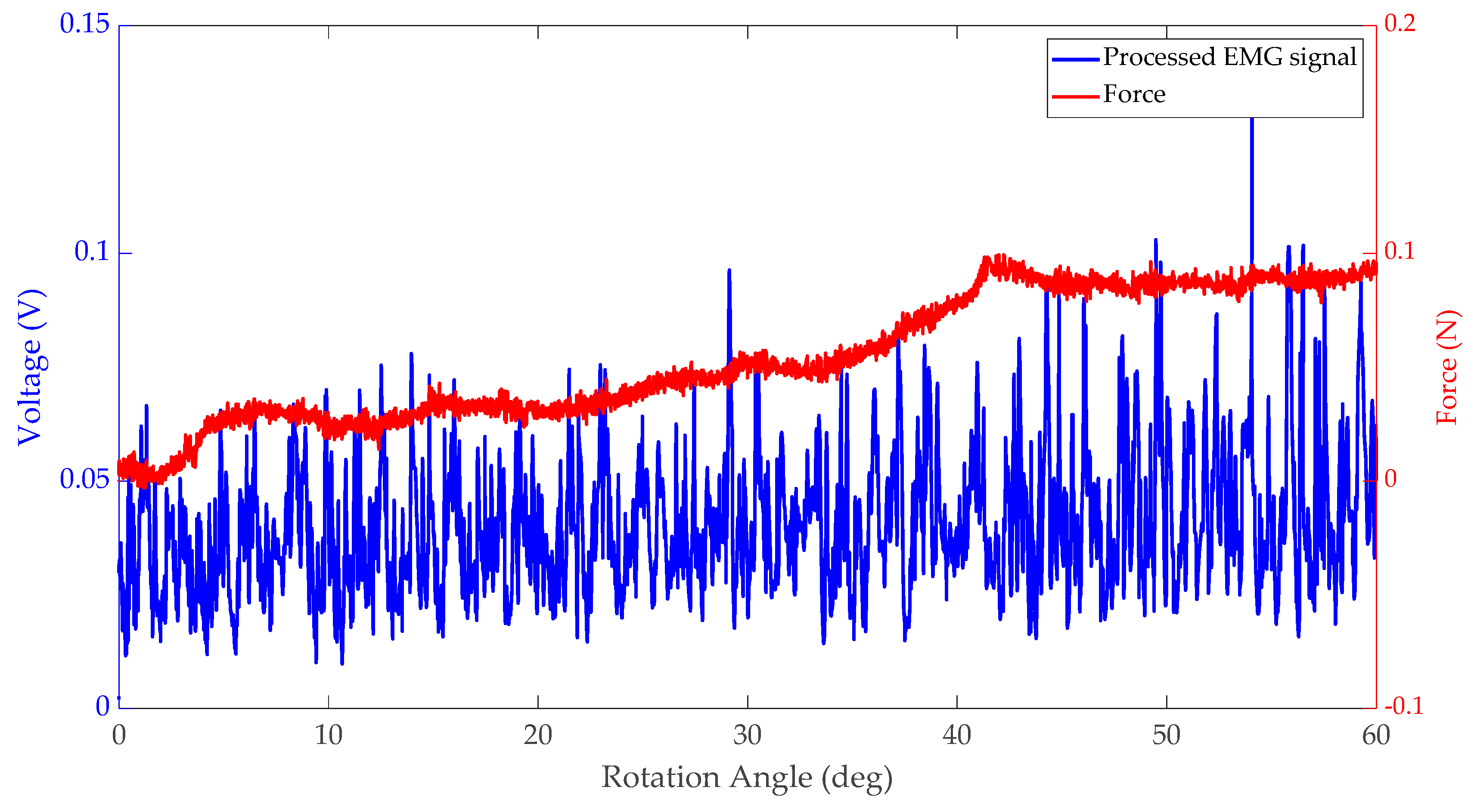
sEMG signal and interaction force during forearm flexion for case one (the motor did not provide the power to the robot frame).
Figure 6.
sEMG signal and interaction force during forearm flexion for case one (the motor did not provide the power to the robot frame).

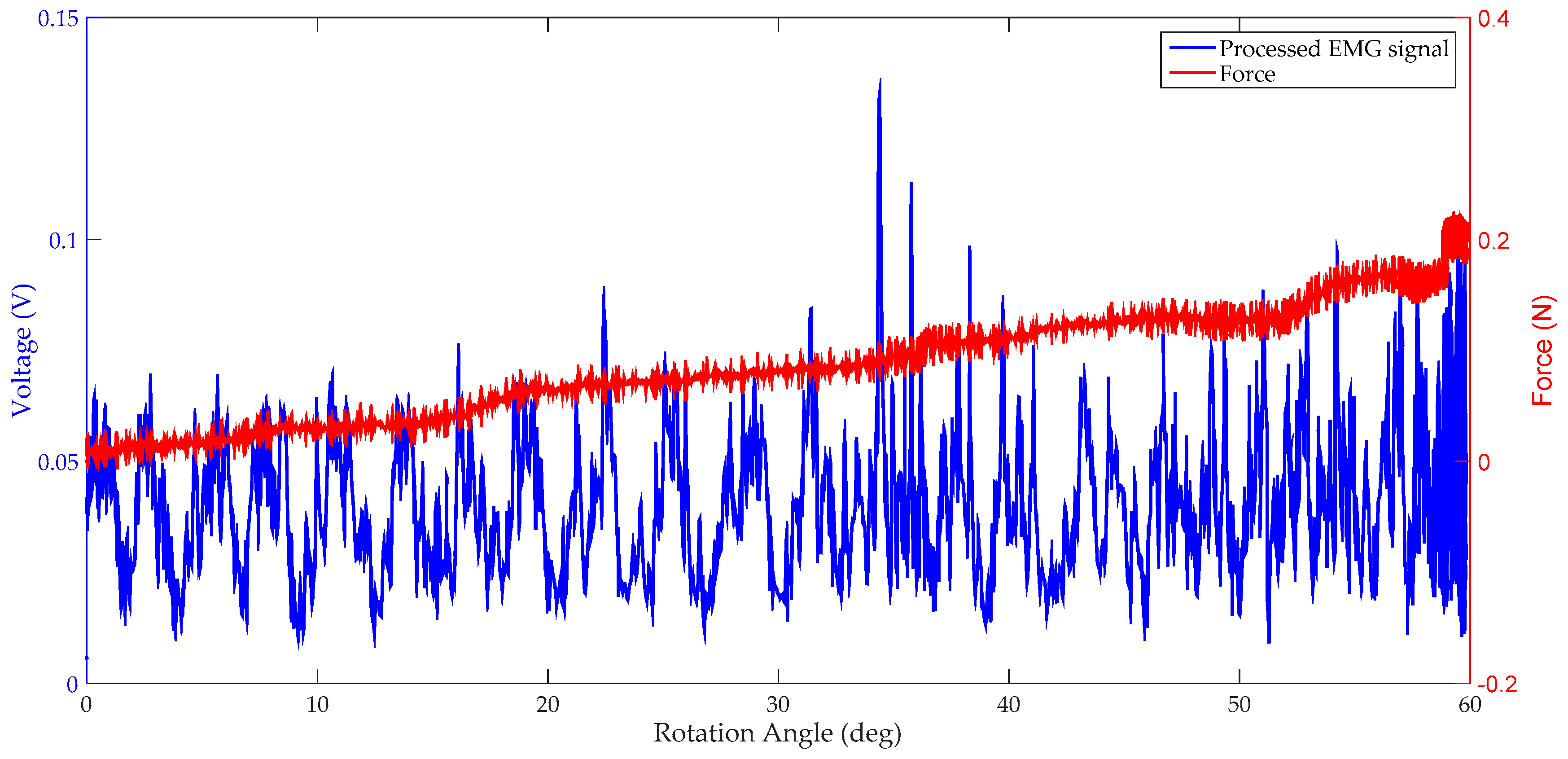
Figure 7.
sEMG signal and interaction force during forearm flexion for case two (the motor provided the power to the robot frame while an impedance controller was applied).
Figure 7.
sEMG signal and interaction force during forearm flexion for case two (the motor provided the power to the robot frame while an impedance controller was applied).

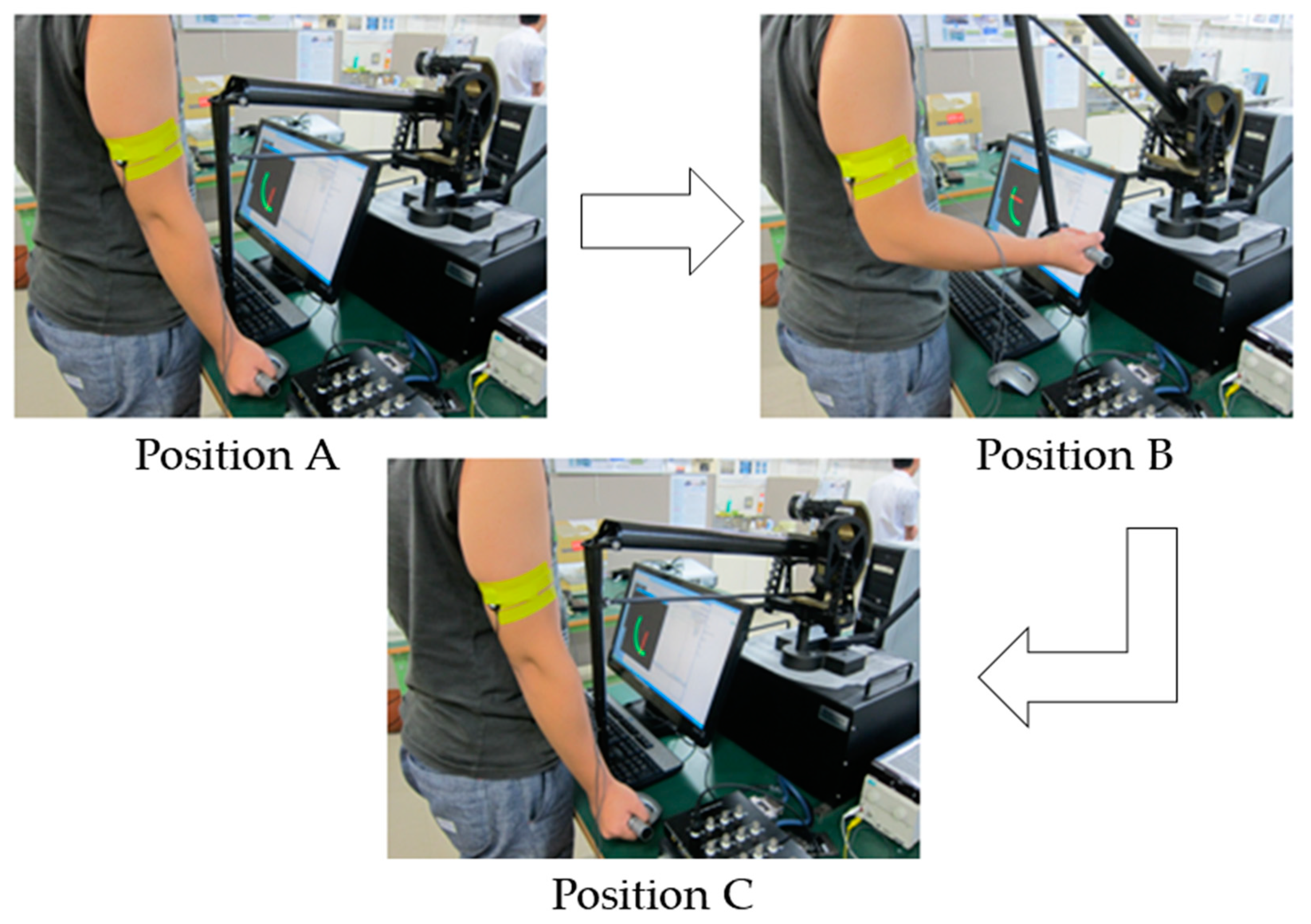
Figure 8.
Experimental process (flex from position A to B and then extend to position C).

Figure 9.
sEMG signals from biceps for three trials.

Figure 10.
Therapist-in-the-loop training via visually shared model.

Figure 11.
Position of the green object and target object in the visual model.

Figure 12.
Position of the orange and purple objects in the visual model.

Figure 13.
Exerted assistive and resistive force by the therapist by means of the exoskeleton.


Table 1.
The coefficients of the Kθ.
| Coefficient | Kθ |
|---|---|
| First trial | 0.005 |
| Second trial | 0.0075 |
| Third trial | 0.01 |
© 2019 by the authors. Licensee MDPI, Basel, Switzerland. This article is an open access article distributed under the terms and conditions of the Creative Commons Attribution (CC BY) license (http://creativecommons.org/licenses/by/4.0/).
Share and Cite
MDPI and ACS Style
Zhang, S.; Fu, Q.; Guo, S.; Fu, Y. A Telepresence System for Therapist-in-the-Loop Training for Elbow Joint Rehabilitation. Appl. Sci. 2019, 9, 1710. https://0-doi-org.brum.beds.ac.uk/10.3390/app9081710
AMA Style
Zhang S, Fu Q, Guo S, Fu Y. A Telepresence System for Therapist-in-the-Loop Training for Elbow Joint Rehabilitation. Applied Sciences. 2019; 9(8):1710. https://0-doi-org.brum.beds.ac.uk/10.3390/app9081710
Chicago/Turabian StyleZhang, Songyuan, Qiang Fu, Shuxiang Guo, and Yili Fu. 2019. "A Telepresence System for Therapist-in-the-Loop Training for Elbow Joint Rehabilitation" Applied Sciences 9, no. 8: 1710. https://0-doi-org.brum.beds.ac.uk/10.3390/app9081710
Note that from the first issue of 2016, this journal uses article numbers instead of page numbers. See further details here.