In this section, we will focus on the two most interesting phenomena, which are derived from the experiments. The first one is the nature of the limiting current density found for bilayer membranes. The second one is the kinetics of the water-splitting reaction in the system with bilayer membranes.
4.1. The Nature of the Limiting Current on Bilayer Membrane
The found values of the limiting currents (ilim) are significantly lower than the values found for the substrate membrane. Moreover, with an increase in the thickness of the cation-exchange layer from 10 to 30 μm, this discrepancy increases.
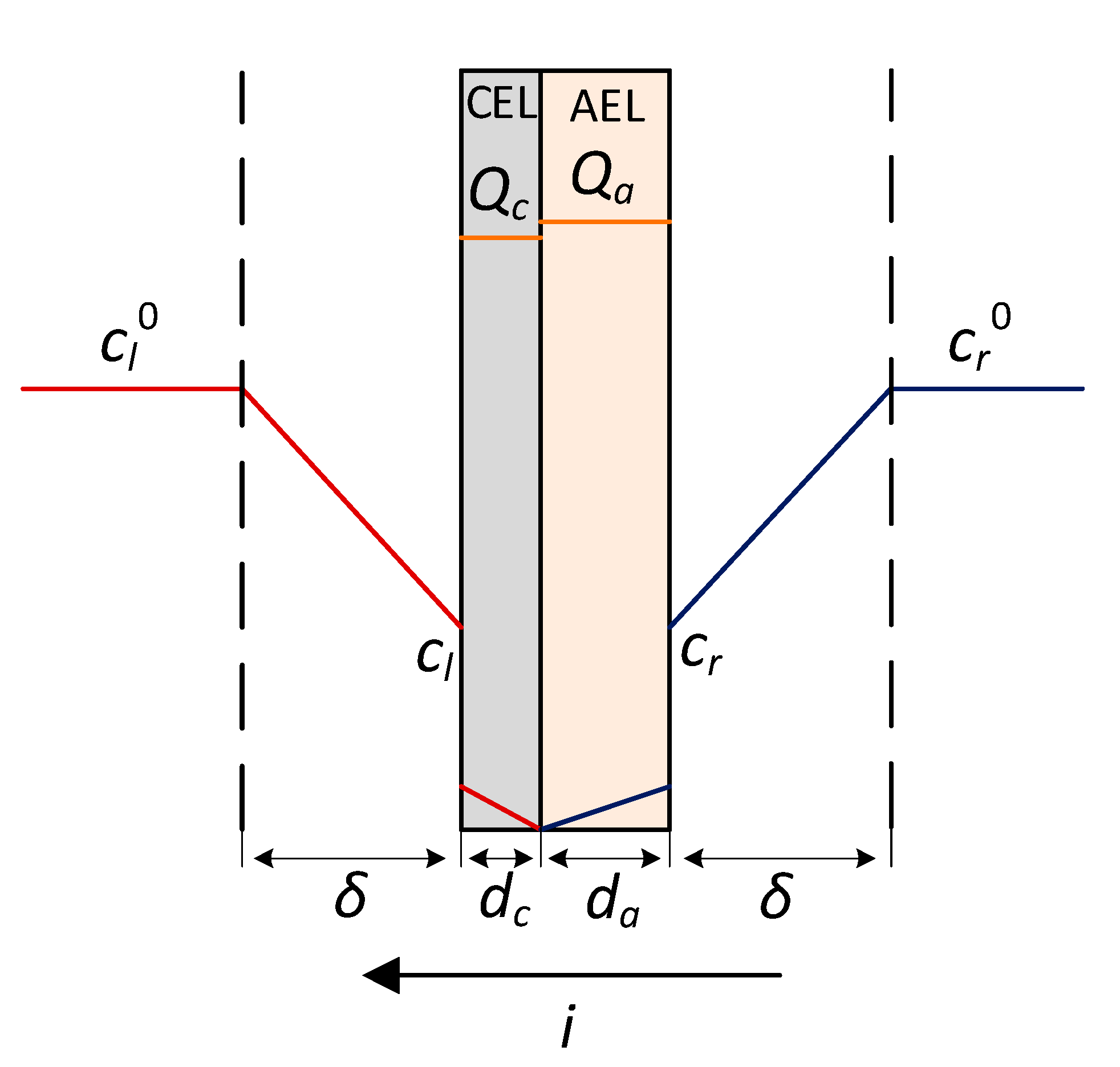
Let us consider the studied BM-a series bilayer membranes as a special case of bipolar ones. The concentration profiles for salt ions in the underlimiting current mode are shown in
Figure 20.
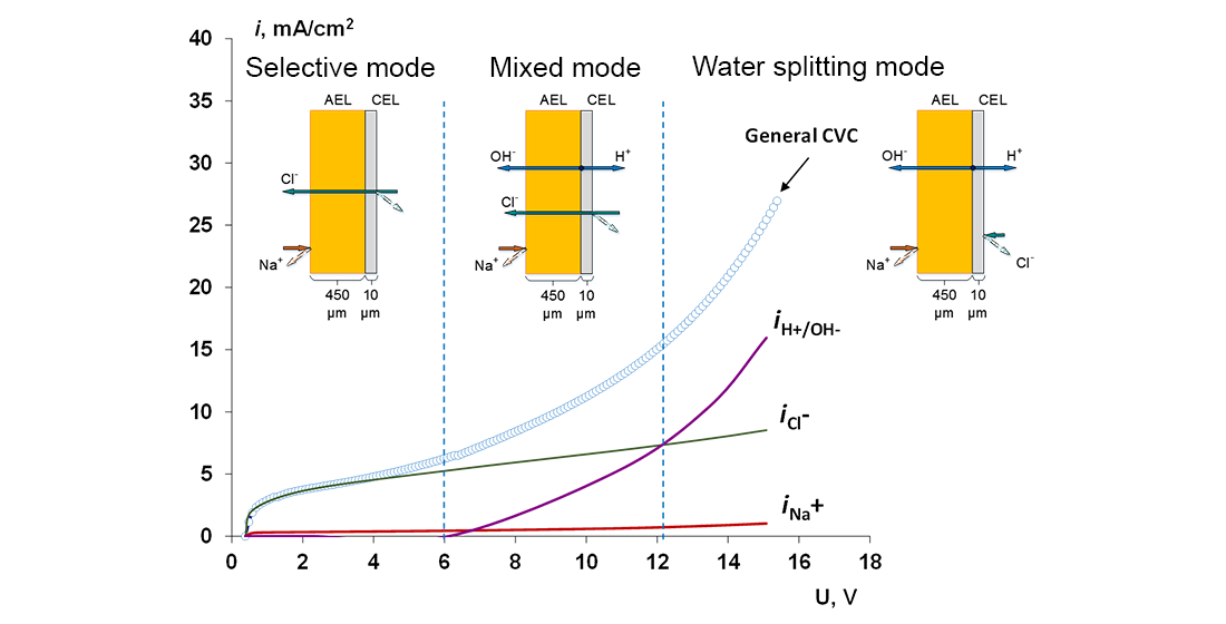
The membrane is in contact with two solutions with equal concentrations and chemical nature from the side of the CEL and the AEL. When the system is in the underlimiting mode (i < ilim), the only charge carriers are salt ions. In the sodium chloride solution, the chloride ion is transported from the left solution into the CEL, and the sodium ion is transported from the right solution into the AEL.
Due to the nature of the bilayer membrane, the concentration of ions is depleted on both sides of the membrane. In the case of a conventional isotropic membrane, the concentration of ions is depleted on one side and is enriched on the other.
The chloride anions penetrate the cation-exchange film as co-ions; hence, their concentration in the CEL will be substantially lower than the solution; usually, it is at least an order of magnitude lower. As a result, the concentration of chloride ions at the CEL/AEL interface reaches zero at currents much smaller than in the anion-exchange membrane-substrate. Thus, the control of the electrodiffusion kinetics passes from the diffusion layer in the solution to the thin cation-exchange layer.
Neglecting the water splitting reaction at the cation-exchanger/anion-exchanger interface, the limiting current density for a bipolar membrane can be expressed as the sum of electrodiffusion limiting currents in each of the layers [
85]:
where:
The reduced current density (which has the dimension of concentration in a square) in Equation (10) is related to the current density, which has the dimension A/m
2, by the following relationship (for a binary 1-1 electrolyte):
In the case of a bilayer membrane, the thickness of the cation-exchange layer is much less than the thickness of the substrate membrane; therefore, we will consider β
c → 0, then substituting Equations (11) and (12) into Equation (10), we obtain the full expression for the limiting current of the bilayer membrane with one thin layer:
Because we consider that, the AEL is thicker than the CEL (d
a ≫ d
c), the second term on the right side of the Equation (13) becomes at least an order of magnitude larger than the first one. Then, only the first term will have a key contribution to the limiting current value. Therefore, for a bilayer membrane with a thin cation-exchange layer, we can write:
For the membrane with the thin anion-exchange layer, the notation in the Equation (14) should be changed to cr, Da, da and Qa, while the above reasoning will also be valid.
In the general case, when a direct current flows in a solution, concentration polarization is observed and the ion concentrations at the membrane/solution interface depend on the current density and cannot be specified exactly. Thus, the properties of the bilayer membrane become dependent on convective-diffusion processes in the external solution.
As an approximation, let us assume that Nernst diffusion layers are formed at the membrane/solution interface (linear concentration profile). Then, the concentration of the binary 1-1 electrolyte at the membrane surface at a certain current
i will be equal to:
Note that, in the general case, the current (
i) in Equation (15) is not equal to the limiting current that is observed experimentally (
ilim in Equation (14)), since the limiting current in the bilayer membrane is determined by the concentration profiles of ions inside the cation-exchange layer. Substituting Equation (15) into Equation (14), we get:
Let’s introduce the notation:
where
is the limiting current determined by a thin cation-exchange layer,
is the limiting current determined by the electrodiffusion of ions in the solution in the absence of a film on the surface of the substrate membrane. Equation (17) for
differs from Equation (14) in that there is no dependence on the electrolyte concentration at the membrane/solution interface, and the value of the limiting current is determined only by the properties of the cation-exchange layer and the concentration of ions in the depth of the solution.
After substituting Equation (17) into Equation (16) and for
i =
ilim we obtain:
The solution to the resulting expression will be:
where
α is the ratio of the values of the limiting currents in the membrane and in the diffusion layer:
where
is some effective diffusion coefficient in a thin layer of a bilayer membrane.
If α takes values less than unity, then we should talk about the limiting current controlled by the membrane. If α takes values greater than unity, then it should be said that the determining mechanism for the occurrence of the limiting state is the electrodiffusion of the electrolyte in the diffusion layer.
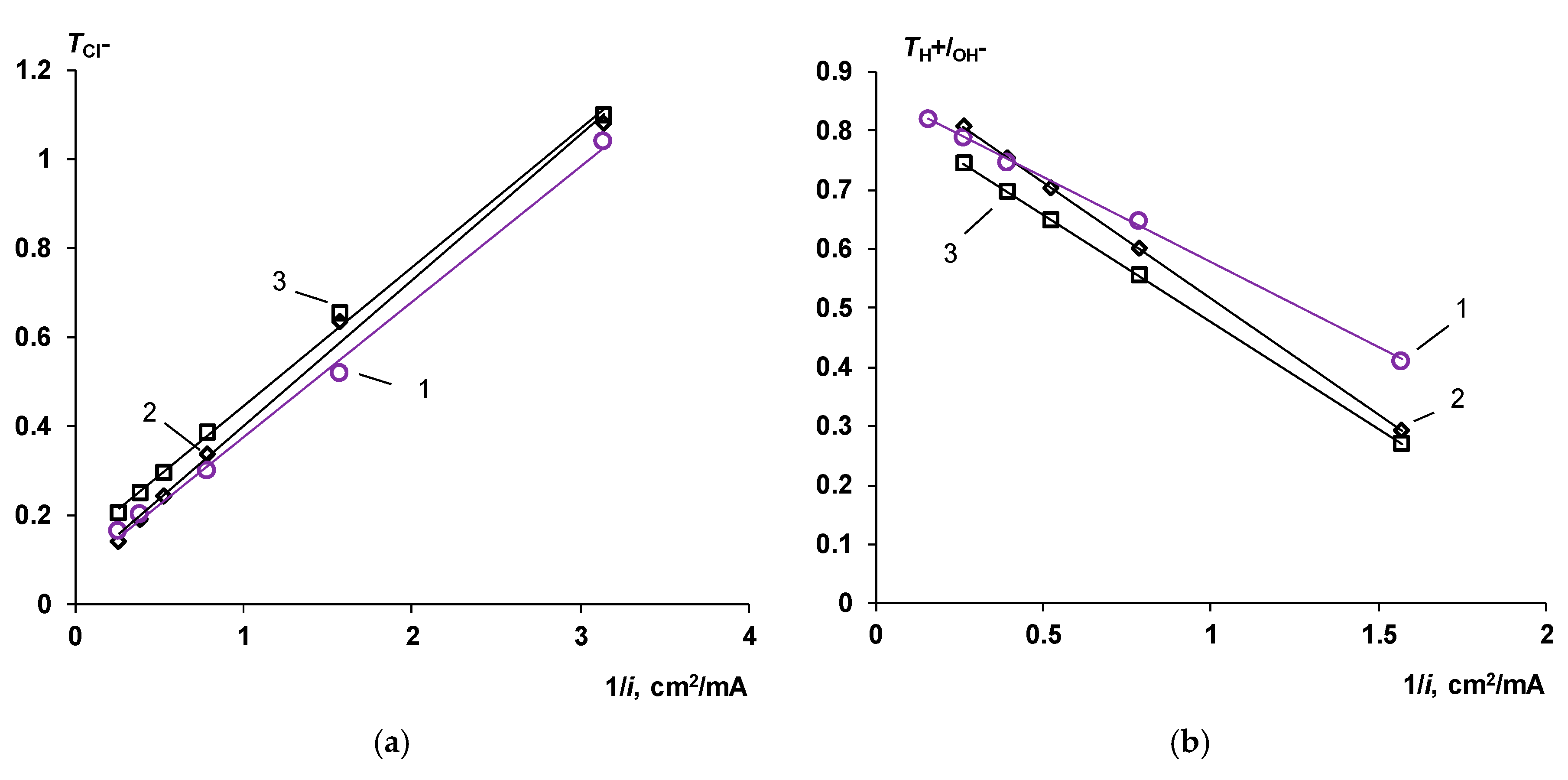
As shown in
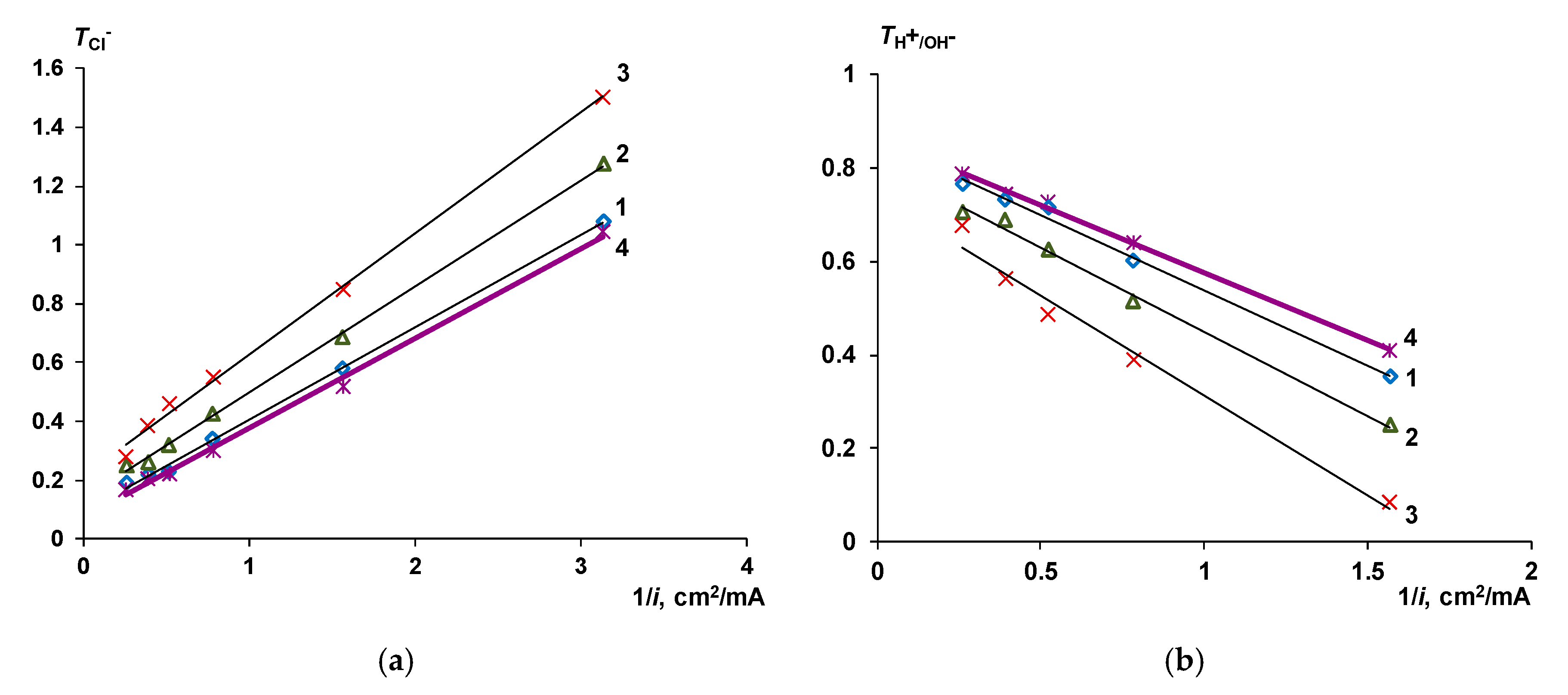
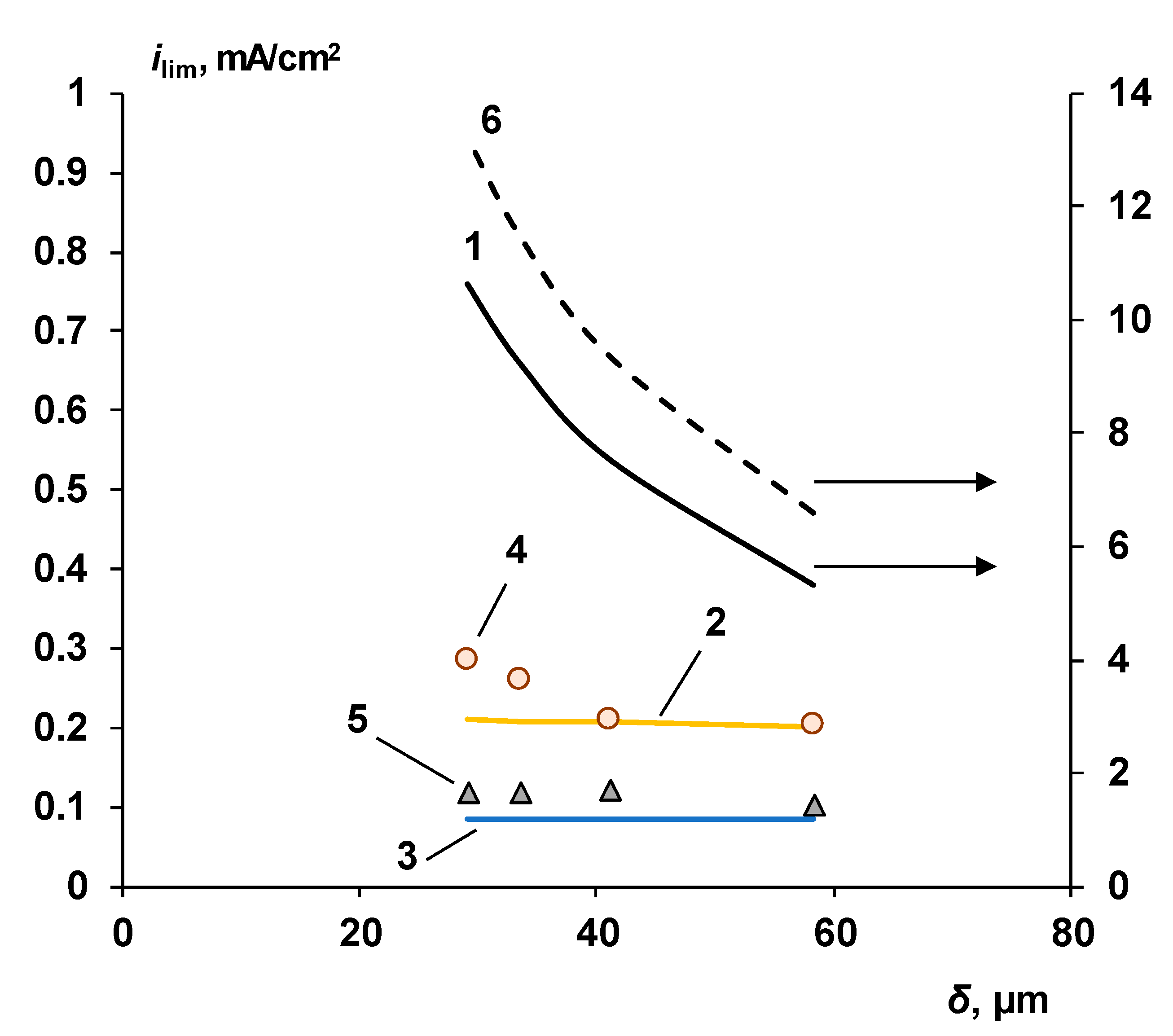
Section 3.1, for membranes with a thin cation-exchange layer, there is an explicit dependence of the transport number of chloride ions, not only on the current density, but also on the thickness of the cation-exchange layer. Earlier, we showed the dependence of the limiting current on the thickness of the cation-exchange layer, calculated theoretically and found experimentally [
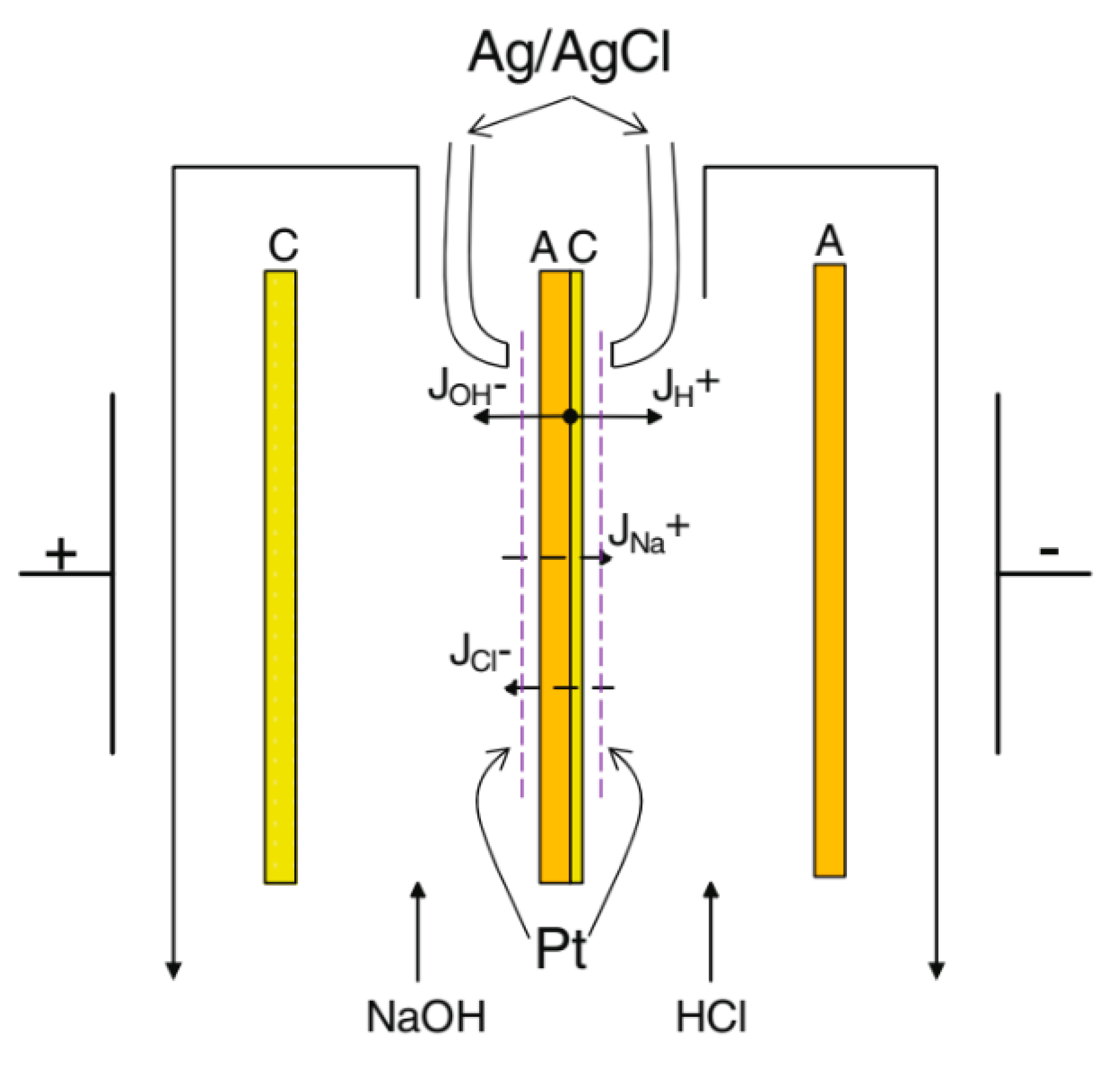
71]. In this case, for BM-a bilayer membranes, there is practically no dependence of the limiting current on hydrodynamics (the thickness of the depleted diffusion layer), as evidenced by the fact that the membrane samples studied using a rotating membrane disk [
77] do not obey the Levich equation (
Figure 21). The limiting current values calculated using Equation (17) are also much larger than the experimentally observed values.
The use of Equation (19) gives satisfactory agreement between the experiment and the calculated values, provided that the value of is of the same order of magnitude as the diffusion coefficient of the electrolyte in solution (Dsol). As a rule, the diffusion coefficients of ions in the membrane are taken to be an order of magnitude lower than in the solution. It should be noted that the obtained equations do not consider the real physical state of both the cation-exchange layer and the substrate membrane. Violations of the integrity of the cation-exchange film, uneven thickness of the film on the surface of the substrate membrane, a large fraction of the intergel solution through which diffusion of co-ions proceeds—all these factors can lead to “overestimated” diffusion coefficients of chloride ions through the cation-exchange layer.
If
taken equal to about 0.1 (from the results shown in
Figure 6, as well as from independent experiments [
87], it was established that the diffusion coefficient of the chloride ion in a cation-exchange layer 30 microns thick is 9.8·10
−7–1.4·10
−6 cm
2/s), then the values of the limiting currents for the studied membranes will be 0.01 mA/cm
2 for the BM-a-10 membrane and 0.004 mA/cm
2 for the BM-a-30 membrane. Note that in real experiments, such values of limiting currents in solutions of corresponding concentrations were not encountered. The reason for such a significant discrepancy between the observed value of the co-ion diffusion coefficient and the limiting current has not been established. In this regard, in Equation (20), the value of the diffusion coefficient (
) is replaced by some effective diffusion coefficient (
).
From the obtained Equation (20), it is possible to estimate the thickness of the cation-exchange layer at which the limiting current in a system with a bilayer membrane is controlled by diffusion, and at which values of the limiting current in the solution and in the film will coincide. For this, the α value must be greater than unity:
If
(for
= 0.01 M);
we obtain:
Thus, the limiting current on a BM-a series bilayer membrane is practically independent of the hydrodynamic conditions in the depleted diffusion layer at a cation-exchange layer thickness of about 25 nm (provided that = 50 microns, = 0.01 M). Even if we take into account the aforementioned condition that , then the CEL thickness should be less than 250 nm thick to change the nature of the limiting current from membrane-controlled to be diffusion-controlled. Since the thickness of the diffusion layer depends on hydrodynamic conditions and, as a rule, is tens of micrometers, the only effective way to increase the limiting current on the bilayer membrane is to increase the concentration of the external solution.
The Co-Ion Leakage through Membranes BM-ac
In the case of BM-ac series membranes with KF-1, the calculations made above cannot be applied, since the structure of such a membrane is much more complicated; in addition, due to the high catalytic activity of KF-1, the flow of the water splitting reaction cannot be ignored even at low currents.
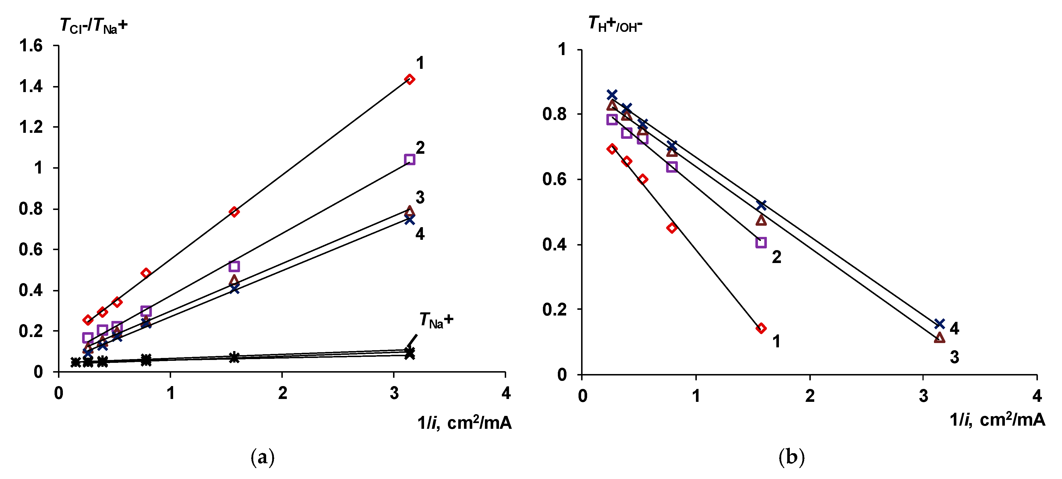
The apparent reason for the appearance of a sufficiently high limiting current (higher than for the BM-a series membranes) is the loss of membrane selectivity. The decrease in the selectivity to hydrogen and hydroxyl ions observed for the BM-ac membranes with 0.2 and 2 mg/cm
2 of catalyst compared with BM-a membranes (
Figure 11) is associated with the complex structure of its cation-exchange layer. The cation-exchange layer of the BM-ac contains microscopic catalyst particles. The presence of mechanical dispersion in the cation-exchange film can lead to the appearance of mechanical irregularities in the cation-exchanger layer, a decrease in the thickness of the film over the catalyst pellets. The presence of large catalyst particles is also important. Those particles may serve as paths for the non-selective transfer of anions. It is known that phosphoric acid ionogenic groups, on the one hand, have high catalytic activity in the water splitting reaction, and on the other, lose their selectivity (the ability to retain anions) when they enter the acid medium [
88], due to the protonation of phosphoric acid groups at low pH values, according to the reactions:
Because of the Reactions (23) and (24), the selectivity of the cation-exchange layer decreases and a non-selective transfer of chloride ions from the acid chamber to the alkaline chamber occurs. At the same time, the thick membrane-substrate prevents the transfer of sodium ions.
In the case of a membrane containing 6 mg/cm2 of catalyst, the main source of non-selective transfer is the physical inhomogeneity of the cation-exchange film. About a third of all particles have a size larger than the thickness of the cation-exchange layer. This leads to its breakthrough by large particles or catalyst agglomerates, the emergence of new pathways for the electrodiffusion transport of chloride ions directly to the surface of the anion-exchange membrane and through it.
4.2. The Water Splitting Reaction Kinetics
The resistance of the bipolar region in Equation (8) is [
79]:
Taking the logarithm from both sides of the Equation (25) leads to a linear dependence of lg
Rb on lg
χ:
with the slope equal to ½.
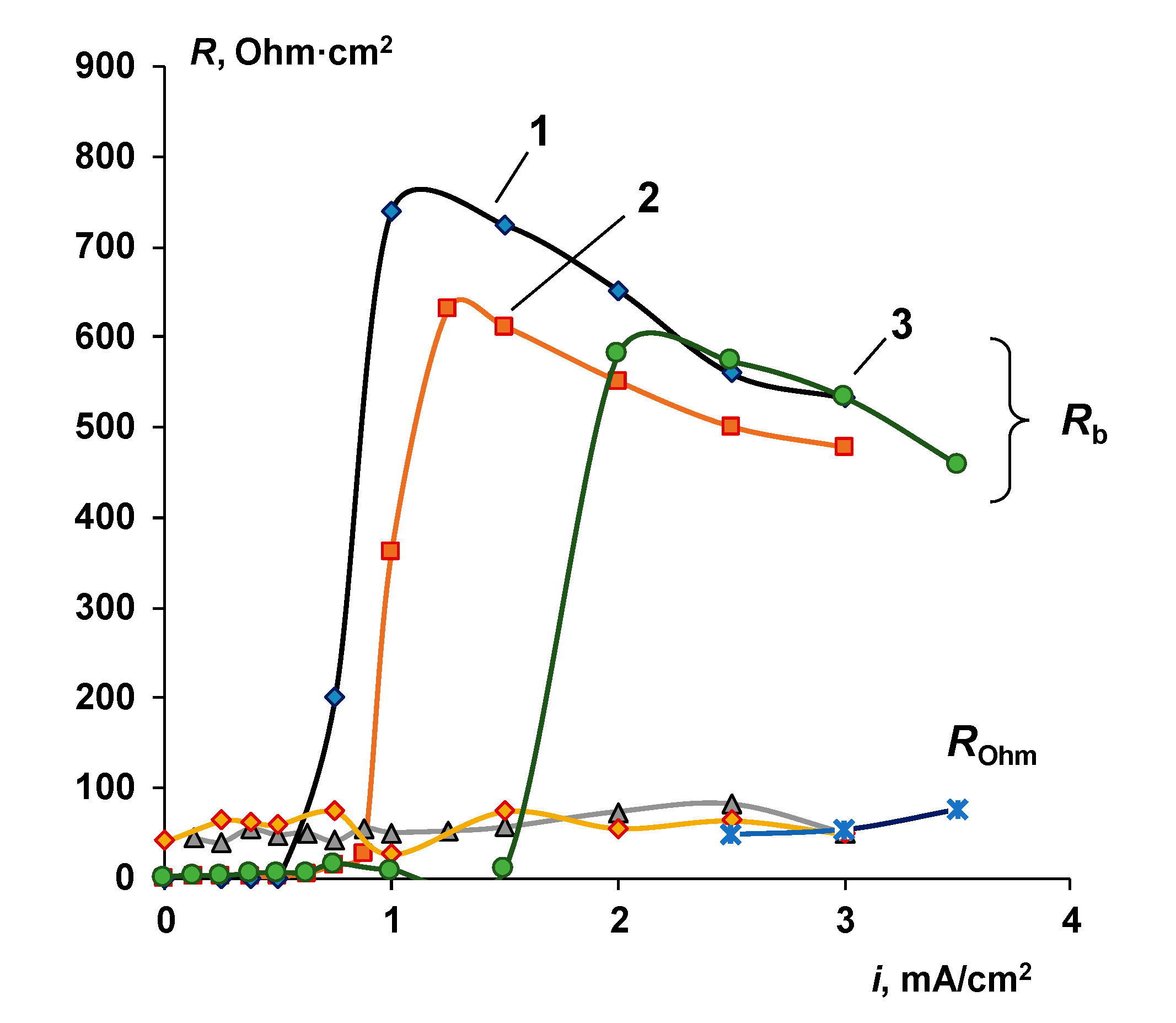
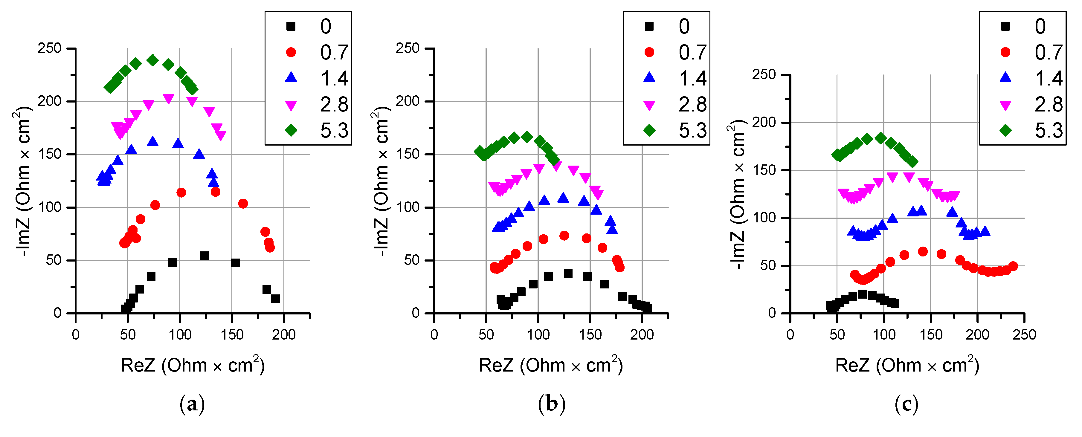
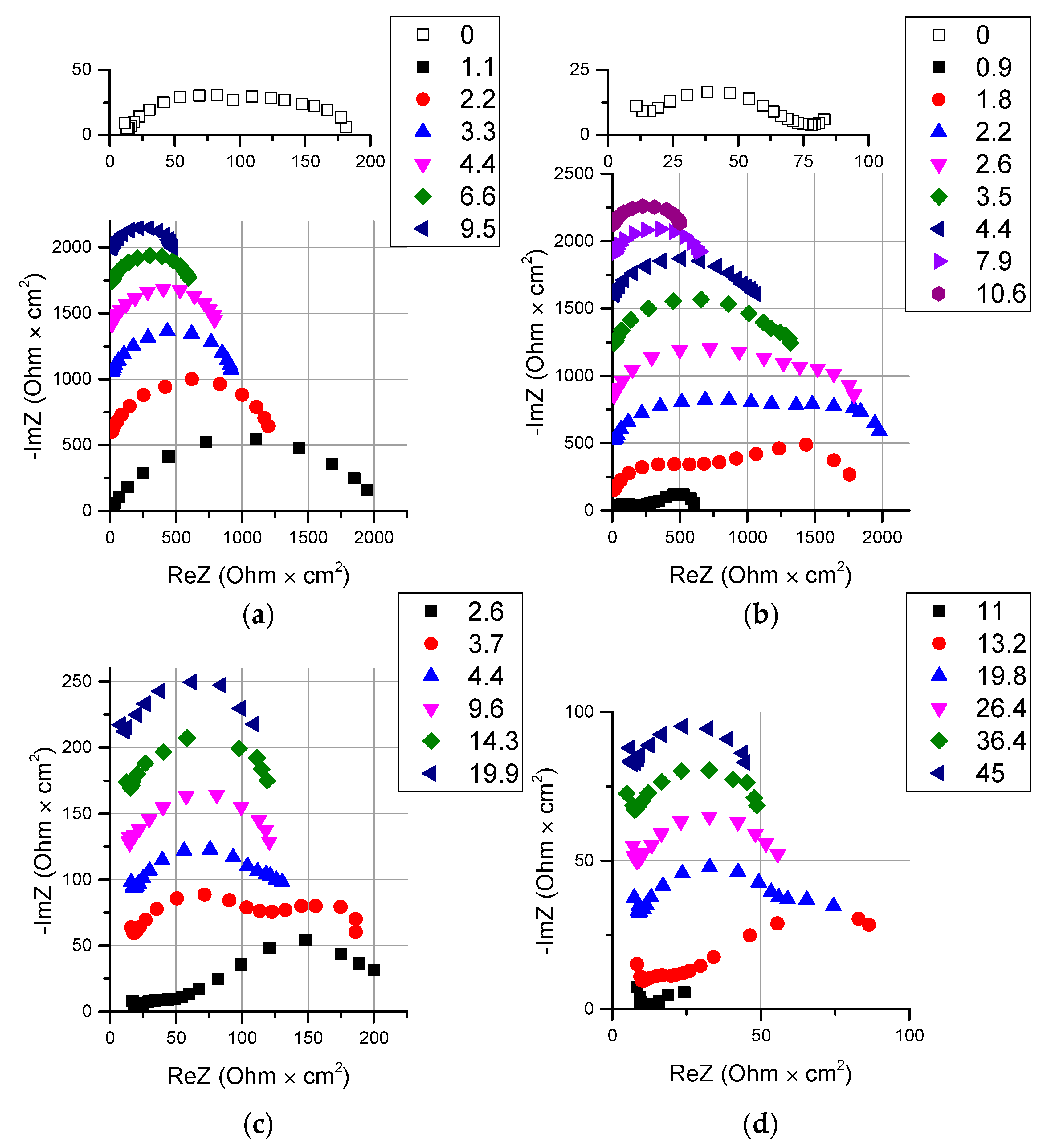
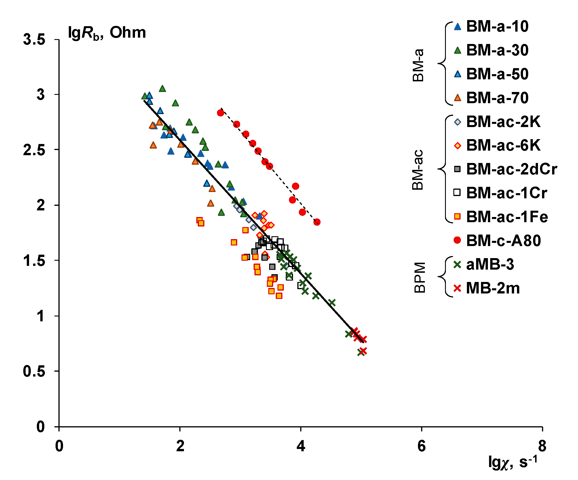
We obtained the values of the non-equilibrium effective rate constants of the water splitting reaction (
χ) and the reaction layer’s resistance (
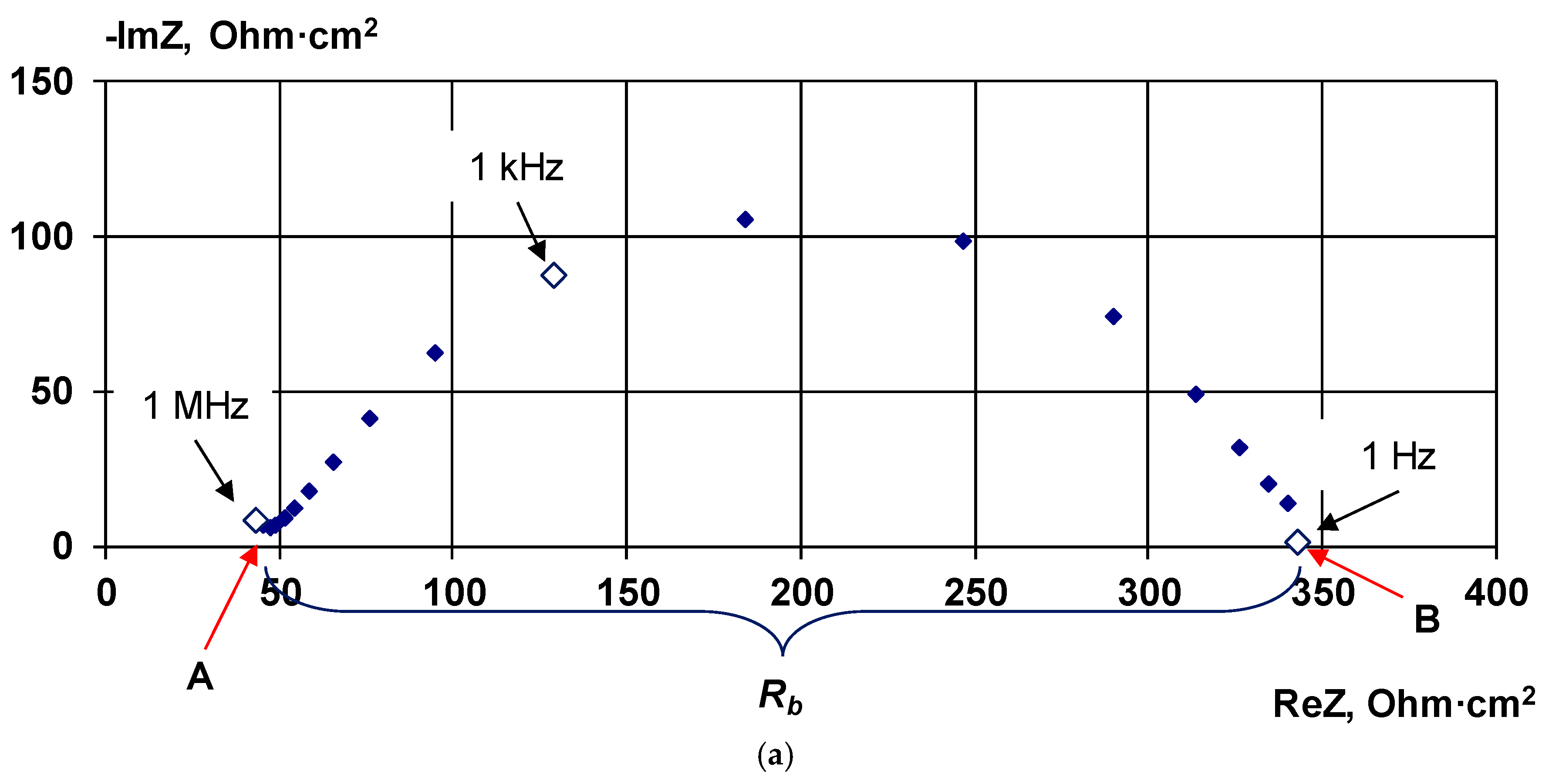
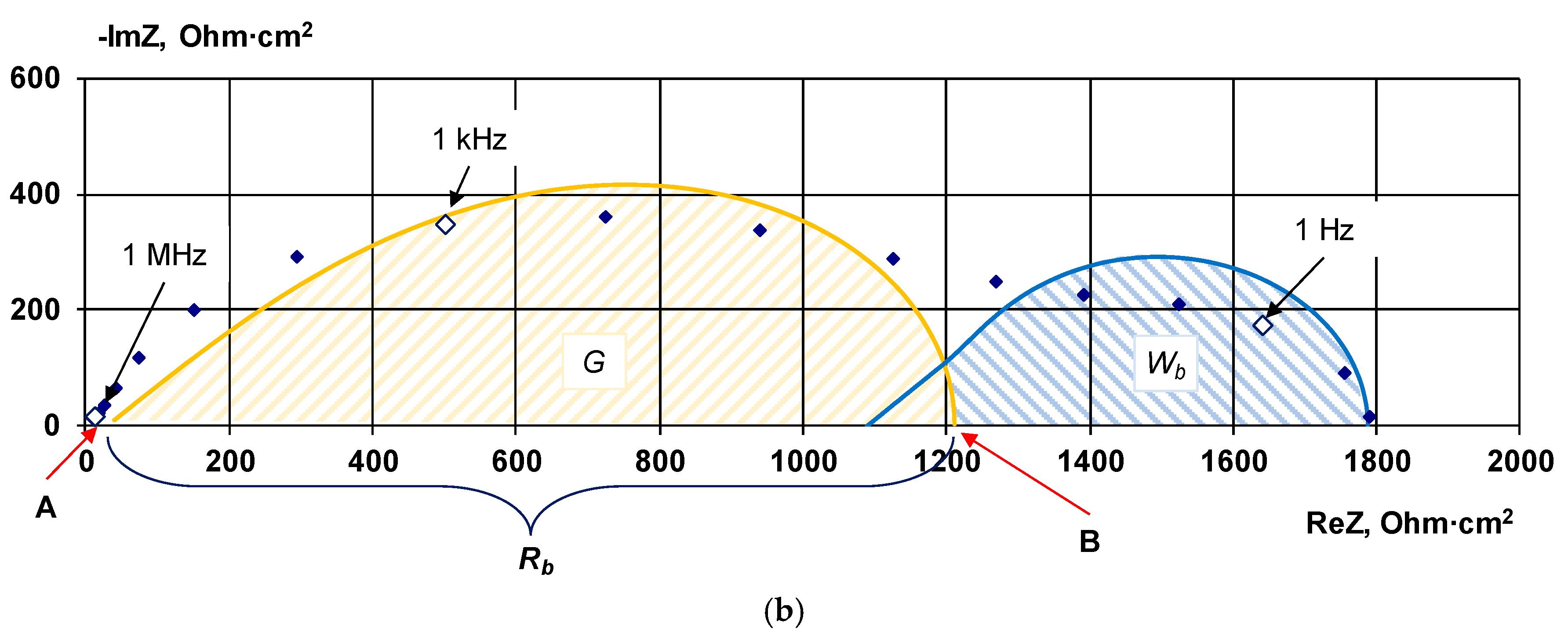
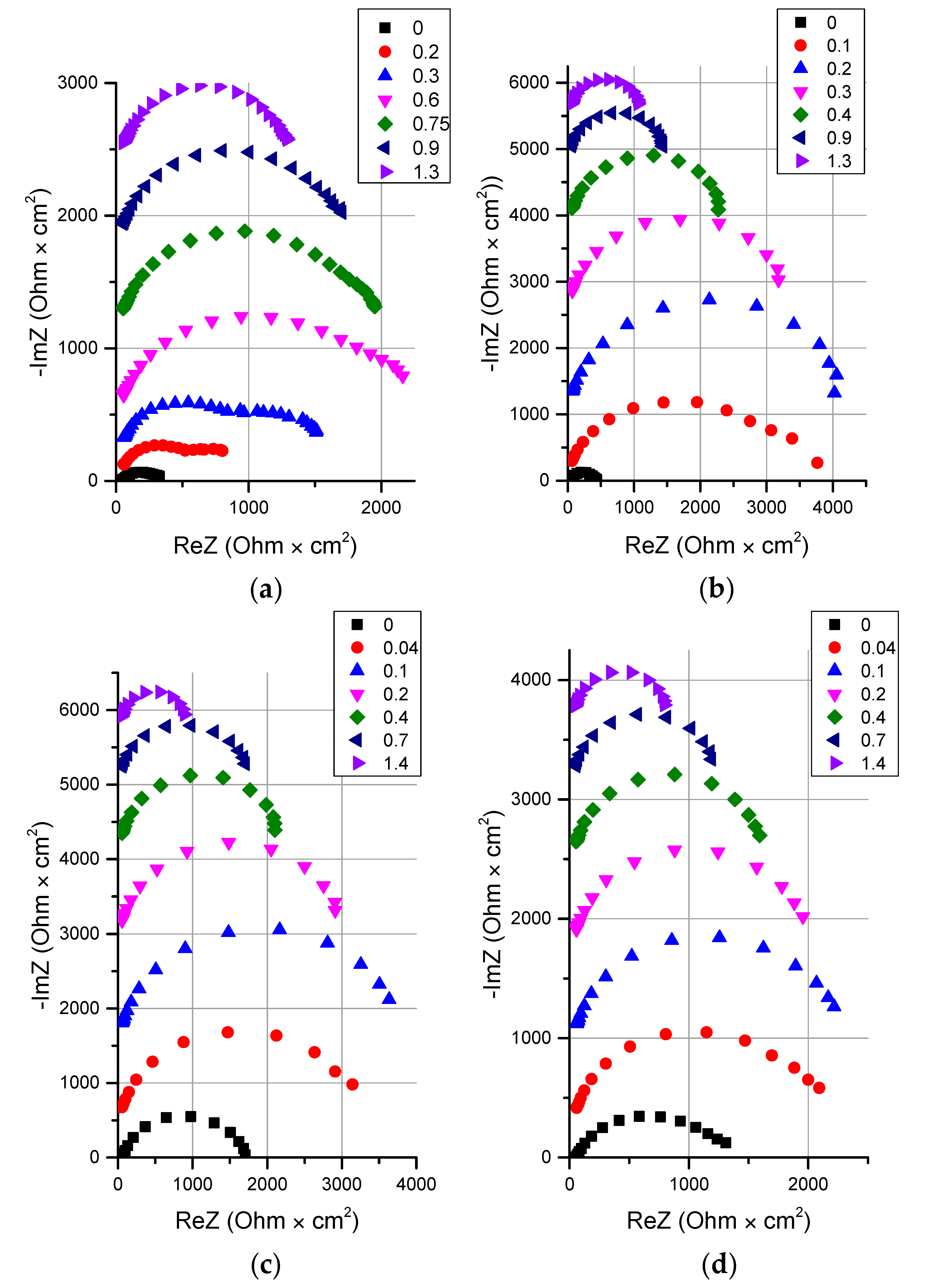
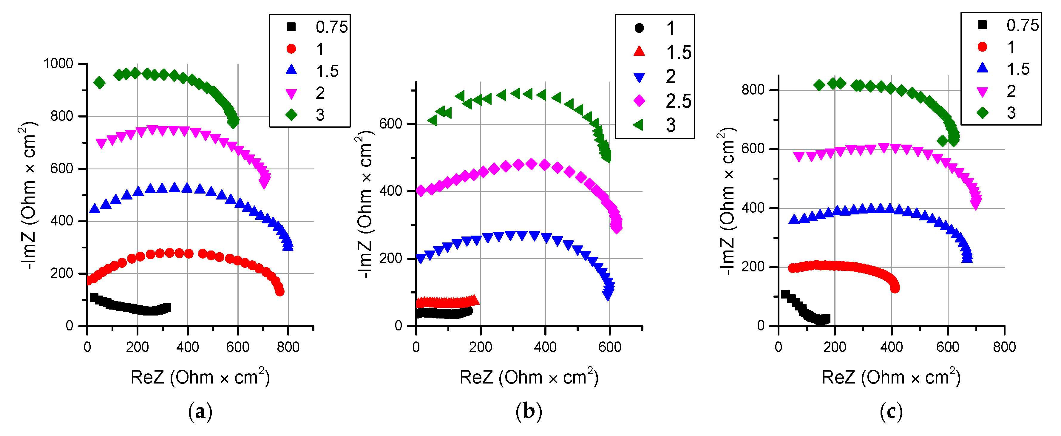
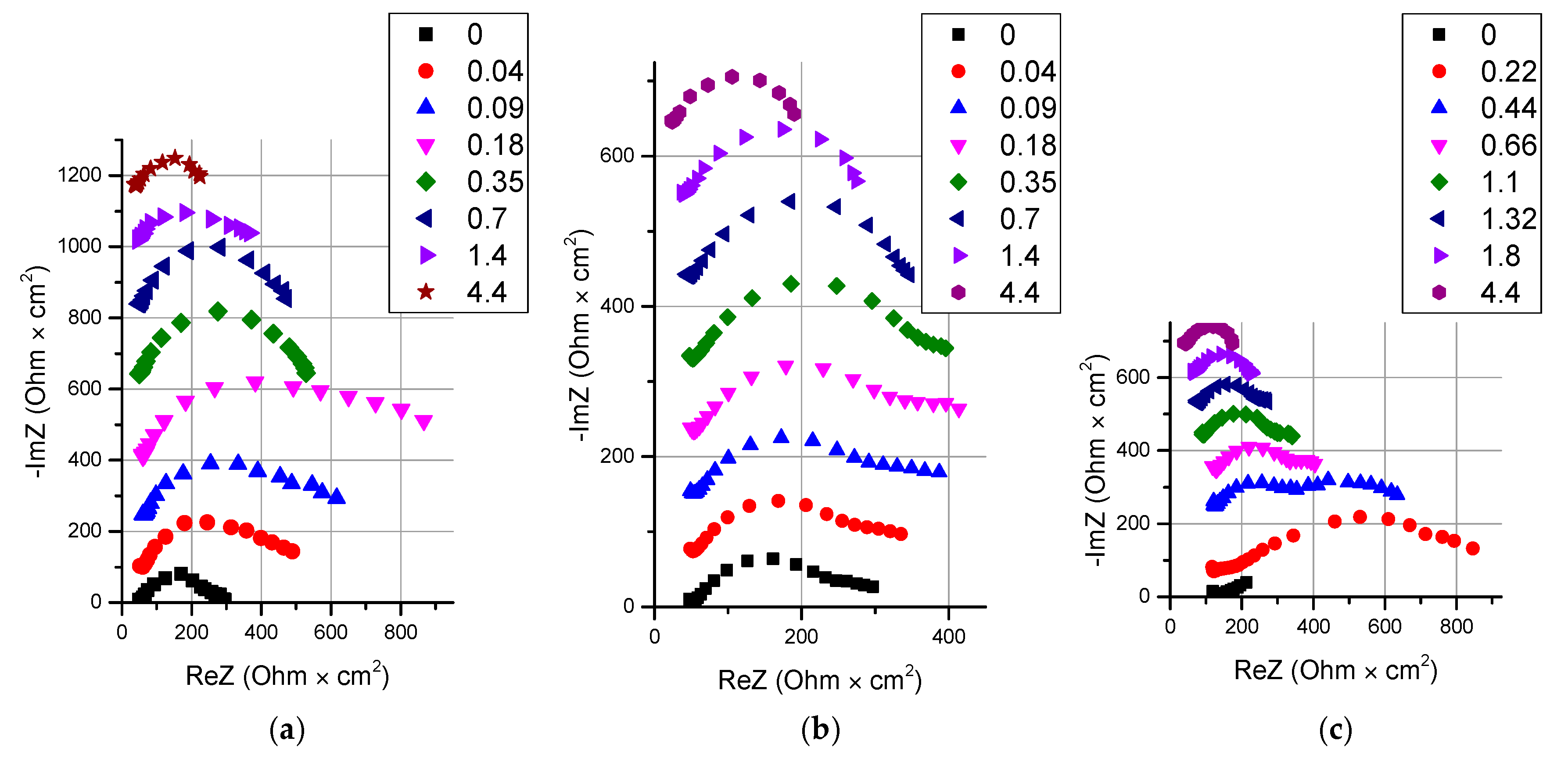
Rb), depending on the current density and the nature of the membrane by numerical fitting of the impedance parameters, according to
Scheme 1 to the spectra of the electrochemical impedance of bilayer membranes presented in
Section 3. The results are shown in
Figure 22.
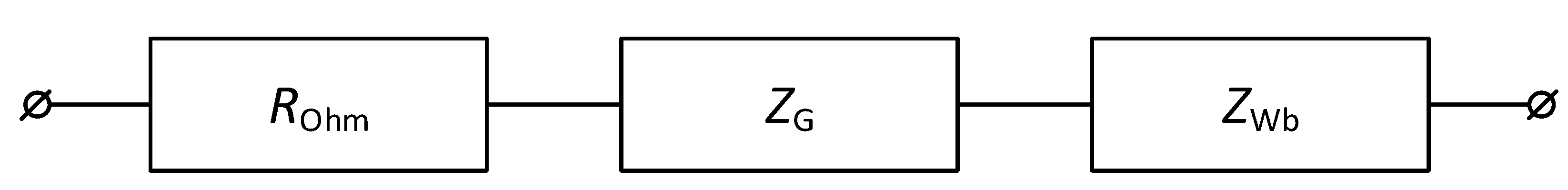
Scheme 1.
The equivalent circuit of the electrochemical impedance of an asymmetric bipolar membrane. ROhm is the ohmic component of the resistance of an electromembrane system, ZG is the Gerischer impedance, ZWb is the finite Warburg impedance
Scheme 1.
The equivalent circuit of the electrochemical impedance of an asymmetric bipolar membrane. ROhm is the ohmic component of the resistance of an electromembrane system, ZG is the Gerischer impedance, ZWb is the finite Warburg impedance
The results obtained both for bilayer membranes with and without a catalyst for the water splitting reaction, as well as for bipolar membranes aMB-3 and MB-2m [
61], generally fall on one straight line in logarithmic coordinates, but the slope of this straight line is 0.60 ± 0.05, which is slightly more than the expected value of ½.
To compare the efficiency of different catalysts with each other, authors of [
89] suggested using the value of the effective water-splitting rate constant in the absence of an external electric field (
kΣ). The
kΣ is independent on current and shows the water splitting efficiency under thermodynamic equilibrium, while
χ is dependent on current. The
kΣ can be found using the experimentally obtained dependence of the partial current by the water splitting products on the magnitude of the overvoltage of the bipolar region (a detailed derivation of the equation can be found in [
71,
89]):
In Equation (27)
Em is a function of bipolar region overvoltage (
) [
89].
Based on the obtained experimental data, using the Equation (27), the effective water splitting rate constant (kΣ) was calculated by minimizing the residual dispersion of the experimental points with respect to the calculated curve.
The calculated values of the effective rate constants of the water splitting reaction for the studied membranes are shown in
Table 6.
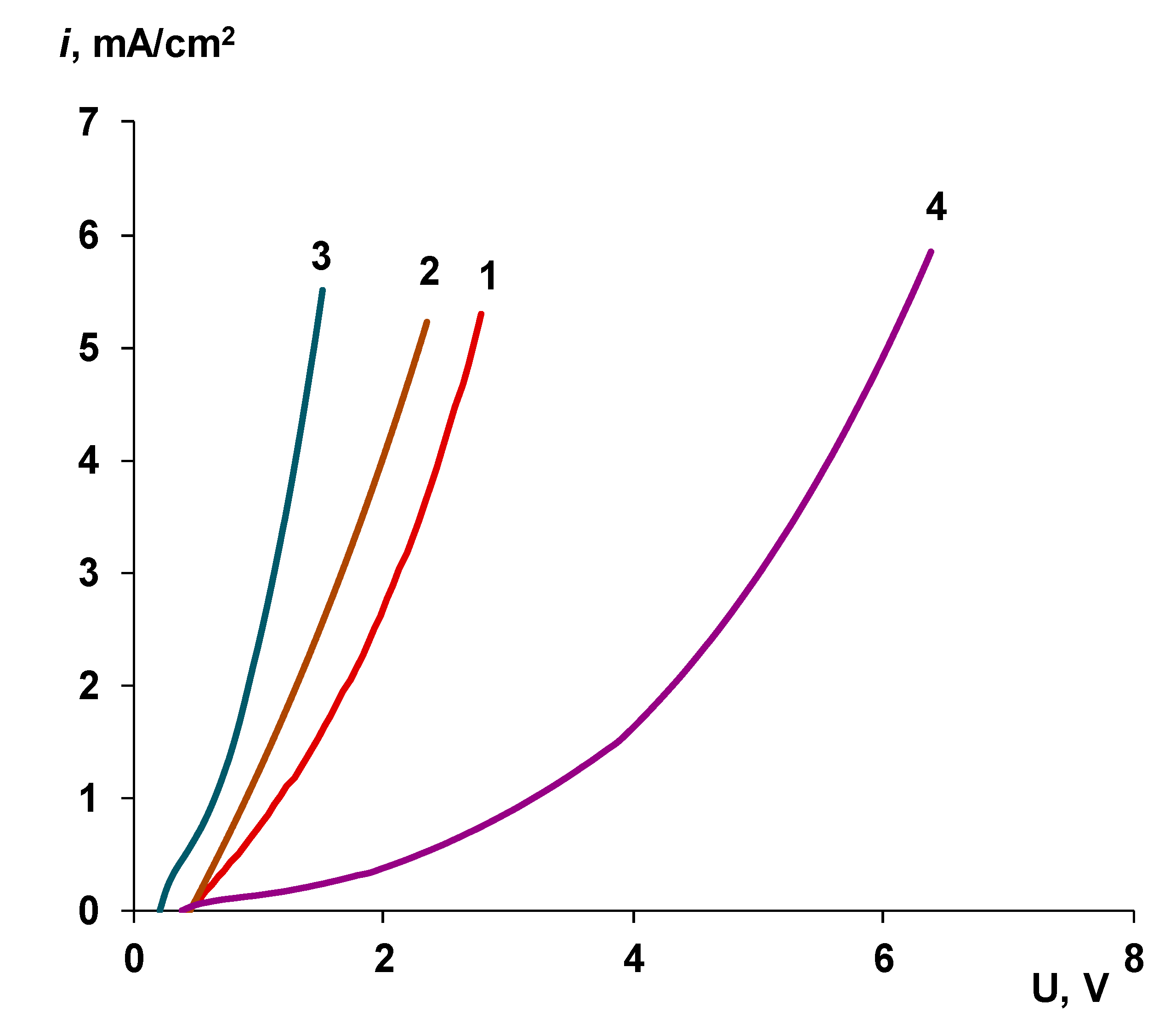
As can be seen from the table, for the BM-ac series membranes with the KF-1 catalyst, regardless of the amount of catalyst, the value of the effective constant
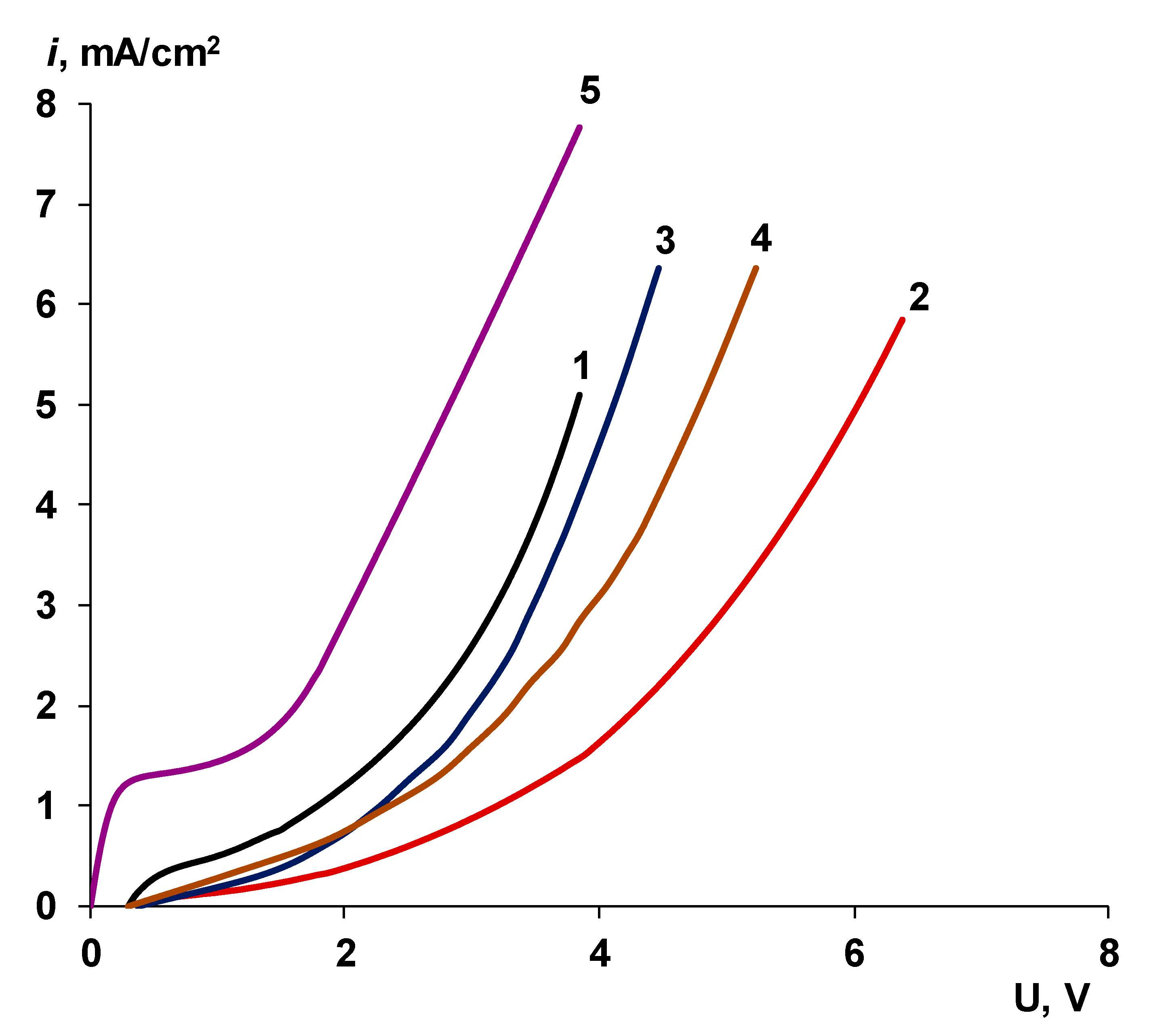
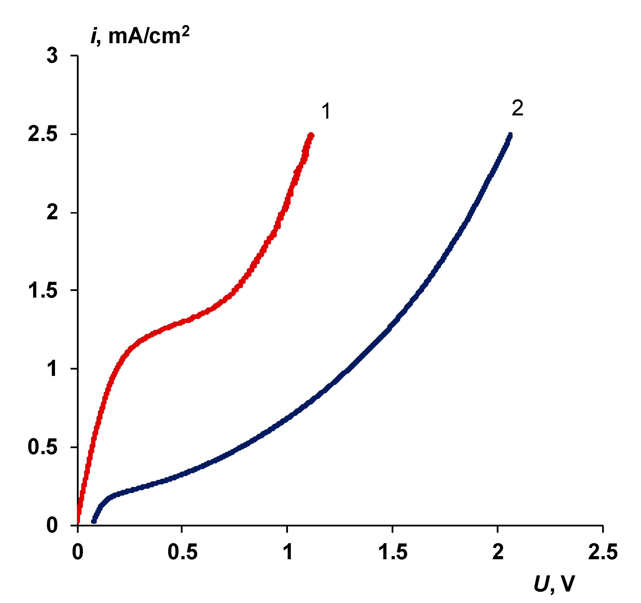
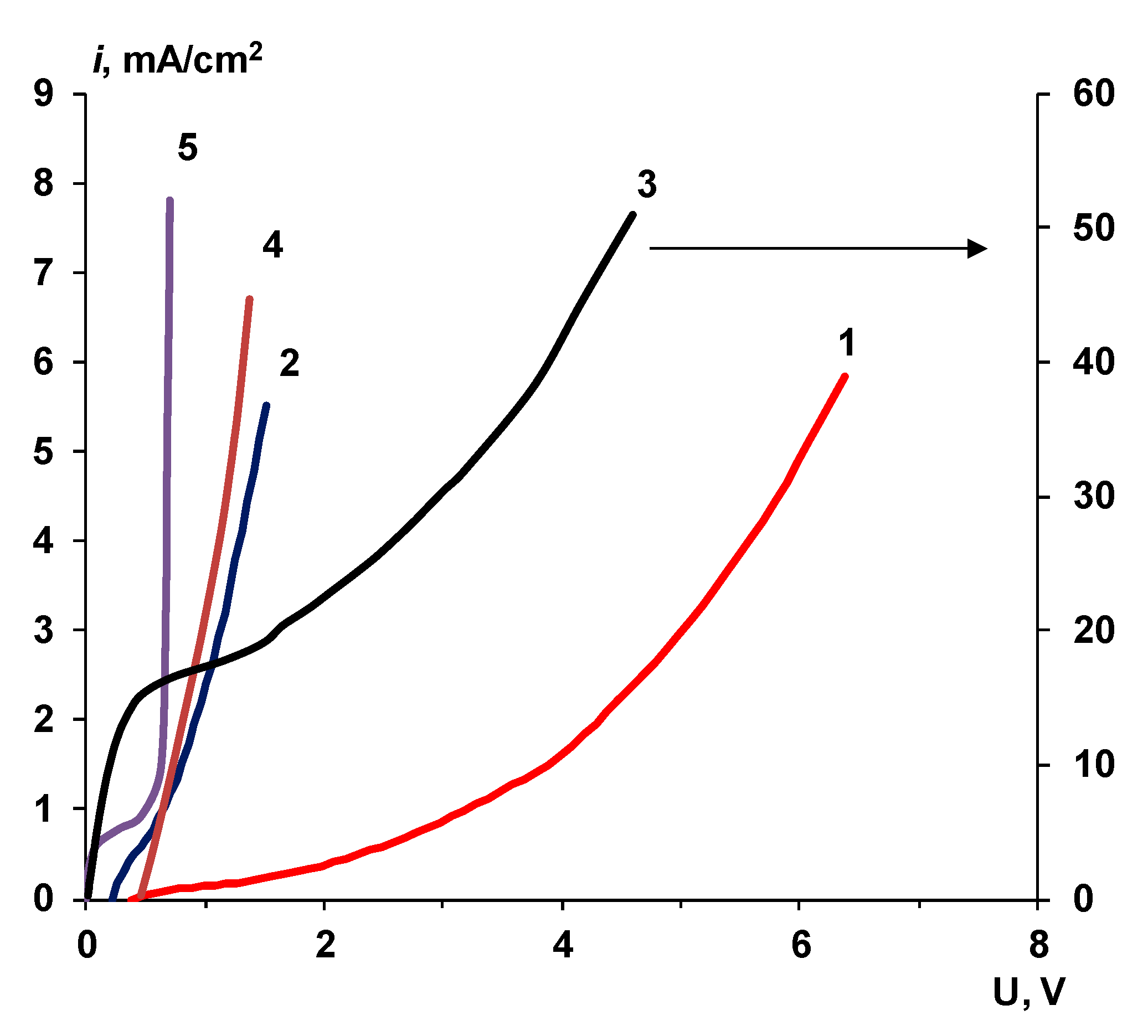
kΣ changes insignificantly. Despite the apparent discrepancy with the voltammetry data, where, with an increase in the amount of catalyst, the voltage drop on the membrane decreases (
Figure 9), this effect is easily explained by the dependence of the transport numbers on the amount of catalyst (
Figure 11). The decrease in selectivity caused by the physical inhomogeneity of the cation-exchange layer leads to a local decrease in the electric field strength in the space-charge region and to a decrease in the effective generating area of the bipolar contact.
In the case of electrodeposited catalysts of chromium (III) hydroxide, it can be concluded that only a small fraction of the area of the heterogeneous catalyst is active in the water splitting reaction, namely, that part that is localized in the space charge region, where the reaction takes place. This is evidenced by the decrease in the effective constant kΣ as the deposition time increases. The part of the catalyst that is outside the space charge region does not participate in catalysis. Since the thickness of the space charge region is about 1–5 nm [
76,
90], only particles deposited directly on the bipolar boundary, even in small amounts, have a significant effect on the voltage drop across the membrane. This conclusion coincides with the conclusions made in [
90]; however, in our work, it is shown experimentally.


