
Mixed-Matrix Membrane Fabrication for Water Treatment


Chemical and Environmental Engineering, School of Engineering, RMIT University, Melbourne, VIC 3000, Australia
*
Authors to whom correspondence should be addressed.
†
Currently on leave from Department of Mechanical Engineering, University of Creative Technology-Chittagong (UCTC), Chattogram 4212, Bangladesh.
Membranes 2021, 11(8), 557; https://0-doi-org.brum.beds.ac.uk/10.3390/membranes11080557
Submission received: 8 March 2021
/
Revised: 10 July 2021
/
Accepted: 16 July 2021
/
Published: 23 July 2021
(This article belongs to the Special Issue Nanofiltration Membranes: Recent Advances and Environmental Applications)
Abstract
:In recent years, technology for the fabrication of mixed-matrix membranes has received significant research interest due to the widespread use of mixed-matrix membranes (MMMs) for various separation processes, as well as biomedical applications. MMMs possess a wide range of properties, including selectivity, good permeability of desired liquid or gas, antifouling behavior, and desired mechanical strength, which makes them preferable for research nowadays. However, these properties of MMMs are due to their tailored and designed structure, which is possible due to a fabrication process with controlled fabrication parameters and a choice of appropriate materials, such as a polymer matrix with dispersed nanoparticulates based on a typical application. Therefore, several conventional fabrication methods such as a phase-inversion process, interfacial polymerization, co-casting, coating, electrospinning, etc., have been implemented for MMM preparation, and there is a drive for continuous modification of advanced, easy, and economic MMM fabrication technology for industrial-, small-, and bulk-scale production. This review focuses on different MMM fabrication processes and the importance of various parameter controls and membrane efficiency, as well as tackling membrane fouling with the use of nanomaterials in MMMs. Finally, future challenges and outlooks are highlighted.
1. Introduction
Membranes can be described as films that act as selective barriers between two adjacent phases that allow the transportation of substances from one compartment to another [1]. Membranes play a vital role in separation technology, as well as in energy applications. Membranes are mostly polymer-based, which is adjusted by their synthesis process for the separation of specific substances, and results in efficient cost-effective separation technology with high performance. However, polymer-based membranes have some limitations due to their unavoidable built-in disadvantages, such as poor chemical and physical resilience.
Mixed-matrix membranes (MMMs) are an important class of organic–inorganic nanocomposite membranes with dispersed nanoparticles in polymeric films. Mixed-matrix membranes are based on either classical porous fillers such as zeolites, porous silica and carbon molecular sieves, or nonporous fillers such as graphene oxide, which has the ability to modify the free volume of a polymer by altering the molecular packing of the polymer chains in the membrane. The typical features of nanoparticles, such as stability, surface-area-to-volume ratio, surface charge, etc. [2], make them excellent candidates for inclusion in polymers for biomedical and environmental applications, including conventional water-treatment processes [3].
In the field of functional membranes, the use of a wide range of nanoparticles and the combination of them with other engineered novel materials gives great scope for engineering the shape and structure of the membranes with the desired performance. As a result, the use of mixed-matrix membranes (MMMs) is under development, in which nanoparticles are used as the filler materials in the polymeric matrix of MMMs [4] for applications such as water filtration, gas separation, fuel-cell application, and pervaporation [5,6,7]. MMMs have been developed substantially as per their applications, and new types of applications of MMMs also have been introduced in the past decade by incorporating inorganic nanomaterials such as metal oxides, including zinc oxide (ZnO) [8], titania (TiO2) [9], iron oxides (Fe2O3, Fe3O4) [10], zeolite [5], silica [11], carbon nanotubes [4], graphene [12], graphene oxide (GO) [13], and metal–organic framework (MOF) [14] as fillers in the polymer matrix.
Currently, MMMs are fabricated using a wide range of fabrication processes based on the membrane materials and their applications. As the effective use of MMMs is increasing due to their various attractive properties, worldwide research on MMMs has experienced exponential growth, as indicated by the number of publications on MMMs in last 20 years (Figure 1).
Due to the significant roles of various fabrication processes on MMMs’ properties, the central focus of this review is the fabrication strategy of mixed-matrix membranes for water purification. We begin our discussion with the crucial issue of membrane fouling and ageing and the use of nanomaterials in membrane technology to address the issue, and then describe various fabrication strategies of MMMs, along with parameters that control membrane fabrication.
2. Membrane Fouling and Ageing: Major Challenges for Water-Separation Membranes
In general, membrane fouling occurs when undesirable particles, macromolecules, colloids, or salts are deposited on the surface of the membrane or inside the membrane’s pores. Membrane fouling can be subdivided into a few categories such as inorganic fouling, organic fouling, and colloidal/biocolloidal fouling, based on the membranes’ separation processes and the foulants’ chemical properties [15,16].
Inorganic fouling occurs due to the higher concentration of inorganic salts, such as sulfates, carbonates of sodium, calcium, etc., mainly when their presence in the solvents is beyond the solubility limits and results in precipitation on the membrane surface or into the pores of the membranes [17]. Organic fouling occurs when irreversible and strong foulants like humic substances, proteins, and polysaccharides are deposited on membrane surfaces [18]. In the case of surface-water, brackish-water, and seawater treatment, the main organic foulant is natural organic matter (NOM) [19]. When the membrane fouling occurs due to the deposition of colloids and the suspension of the nanoparticles or microparticles, it is known as colloidal fouling. There are three types of colloids [20,21]: organic colloids such as natural organic matter, proteins, etc.; inorganic colloids such as SiO2, iron oxides, and hydroxides of iron and heavy metals; and biocolloids such as viruses, bacteria, and other types of microorganisms. Biocolloid-induced membrane fouling is also called biofouling [22], and is caused by a range of bacteria like Aeromonas, Corynebacterium, Bacillus, Flavobacterium, Pseudomonas, and Arthrobacter, and also by fungi like Trichoderma, Penicillium, and other eukaryote microorganisms [23]. As a result, this foulant layer affects the permeate flux in two different ways [24,25]: first by creating an additional hydraulic resistance that results in low water flux and membrane permeability at a fixed applied pressure, which can be overcome by applying higher pressure; and also by the formation of a porous cake layer inside the unstirred cake layer, resulting in a higher concentration polarization, which leads to higher solute concentration on the membrane surface, as well as an increase in the osmotic pressure of the membrane surface and a decrease in the membrane flux.
Thus, it is widely recognized that the adherence of organic compounds and biocolloids to the surface of the membrane is the key parameter for the fouling of the membrane, and this adherence ability of the foulants is influenced by hydrogen bonding, London–van der Waals attractions, and hydrophobic and electrostatic interactions [18,26]. From the above discussion, it is evident that the inhibition or minimization of the fouling process might be possible by preventing the adhesion interactions between the membrane and the foulant. This could be possible through the development of MMMs with appropriate physiochemical properties, which could combine an efficient separation process with lower membrane fouling.
Additionally, various hydraulic cleaning procedures have been introduced for reversing or reducing membrane fouling [27]. Membrane backwashing with clean water is a common practice for foulant removal. After repeated filtration and backwash cycles, some materials are adsorbed on the membrane surface and need to be washed by a cleaning agent like hypochlorite for ultrafiltration membranes, as they cannot be removed otherwise [27]. Long-term exposure to foulants and cleaning agents has been reported to irreversibly change the performance and characteristics of membranes; these irreversible changes are defined as membrane ageing [28]. The characteristics of membranes are mainly chemical composition, pore size, etc.; and membrane performance factors are fouling rate, clean membrane resistance, etc. The main limitation is that complete full-scale ageing studies need many years of observation and cannot be controlled rigorously [29].
2.1. Effect of Membrane Surface Properties on Fouling and Ageing
The interactions between a membrane and foulants are determined by the membrane’s surface properties such as hydrophobicity or hydrophilicity, surface charge, and surface roughness [30,31].
2.1.1. Hydrophilicity and Hydrophobicity of Membrane Surfaces
Usually, a membrane’s hydrophilicity or hydrophobicity is evaluated with a wettability study using contact-angle measurement [32]. The commercial membranes are mostly fabricated from hydrophobic polymers with high thermal, chemical, and mechanical stability, including polysulfone (PSF), polyethersulfone (PES), polyvinylidenefluoride (PVDF), polyacrylonitrile (PAN), polypropylene (PP), polyethylene (PE), and polyamide (PA) [1]. These polymers exhibit a high contact angle, which leads to the adsorption of different solutes from the feed. It is established that a higher mass per unit area of hydrophobic solute is adsorbed by membranes with high contact angles than that by the membranes with a lower contact angle [33]. On the other hand, hydrophilic membranes attract fewer charged inorganic particles, microorganisms, and organic substances, and result in less fouling [34,35].
2.1.2. Surface Charge
In the case of charged foulants, membrane fouling can be controlled by the electrostatic charge of membranes. Membranes possessing the same charge as that of the foulants will reduce membrane fouling due to electrostatic repulsion occurring between the foulant and the membrane, which prevents foulant deposition on the membrane (Figure 2) [36,37]. Therefore, fouling can be reduced by incorporating ionizable functional groups on the surface of the membrane. For example, in protein filtration, when the protein is negatively charged at neutral pH, a negatively charged membrane surface could be a better choice [1]. Similarly, for organic compounds with a positive charge, the positively charged membrane surface is the solution for low membrane fouling [38]. So, low-fouling membranes could be fabricated and developed by considering the potential foulant’s charge on the membrane surface and inside the membrane pores from feed streams.
2.1.3. Surface Roughness
Membrane fouling and surface roughness are strongly related to each other in nanofiltration (NF) and reverse osmosis (RO) membranes. Smooth and hydrophilic cellulose acetate (CA) RO membranes have less tendency toward colloidal fouling than hydrophobic and rough PA membranes [38]. Table 1 shows the relationship between surface roughness and relative fluxes for filtration of a sodium chloride solution containing silica particles with commercial NF (Osmonics HL, Dow-FilmTec NF-70) and RO (Trisep X-20, Hydranautics LFC-1) membranes. From the tabulated data of their flux and surface-roughness values, it is clearly visible that the flux decreased with the increase of surface roughness of the membrane during the filtration process. The increase in membrane surface roughness also led to an increase in the total surface area, resulting in more foulant attachment on the surface, and a ridge–valley structure also favoring the accumulation of foulants at the membrane surface. Using atomic force microscopy (AFM), Vrijenhoek et al. [40] showed that colloidal particles mostly accumulate in between the valleys of rough membrane surfaces, which results in valley clogging and causes lower flux and permeability than the membranes with smooth surfaces.
Considering all the above points, it is clear that the top membrane layer is the key area to control the fouling process, so the main goal could be the surface modification of the membrane to develop a low-fouling composite membrane by introducing polymer brushes and charged groups on the membrane’s surface, as well as hydrophilization and creating smooth surfaces, which would minimize the undesirable interactions between the foulants and the membrane surface for low or zero fouling of the membrane.
3. Mixed-Matrix Membrane Materials
3.1. Polymers
3.1.1. Glassy and Rubbery Polymers
In water-treatment processes, various polymers have been used in MMMs; some polymers employed are rubbery (e.g., polyethylene oxide) [41], but most are glassy (e.g., aromatic polyamides, cellulose acetate, and polysulfone). Classifying membranes for water-treatment processes as rubbery or glassy can be complex, since they are operated under hydrated conditions and can absorb substantial amounts of water (i.e., ~10–50 vol% water) [42,43,44].
Recently, ion and water transport in glassy hydrated polymers has been reported, and has become a topic of interest in the membrane field [45,46,47,48,49]. Xie et al. measured water and salt transport in a disulfonated poly (arylene ether sulfone) copolymer (i.e., BPS-32) [45]. BPS-32 was synthesized in the potassium counter-ion form (K) and acidified to the acid form (H), either in solid state or in solution, and subjected to various ion-exchange steps and thermal treatments. Due to its relatively high Tg (278 °C), the membrane remained glassy upon hydration, and therefore its processing history had a profound impact on its water and salt transport properties.
More recently, Chang et al. prepared two chemically similar copolymers, rubbery 2-hydroxyethyl acrylate-co-ethyl acrylate (HEA-co-EA) and glassy 2-hydroxyethyl methacrylate-co-methyl methacrylate (HEMA-co-MMA), to probe the impact of polymer backbone dynamics on ion and water transport properties [48,49]. Both had similar and relatively low water contents (~8% by mass). However, the rubbery membrane had salt permeability coefficients roughly 2–3 times higher than those of the glassy membrane. In a later study, Chang et al. reported water dynamics and tortuosity in the same membranes over several length scales [49]. Using pulsed-field gradient nuclear magnetic resonance (PFG NMR), they measured water diffusivity as a function of diffusion encoding time. The longer the diffusion encoding time, the greater the length scale over which diffusion was measured. Water-diffusion coefficients decreased with increasing encoding time, plateauing at long times as water-molecule diffusion became increasingly hindered by the polymer segmental obstructions on longer length scales. The long-duration plateau value of water diffusivity was regarded as equivalent to the value observed in measurements of bulk-transport properties [49]. Salt solubility and diffusivity were measured via equilibrium and kinetic desorption techniques, respectively. Equilibrium water solubility was also measured. Using the solution-diffusion model, water and salt permeabilities were calculated from these data. Water and salt diffusivity and permeability were lower in the glassy polymer than in the rubbery polymer. However, water/salt selectivity was enhanced in the glassy membranes, corroborating the enhanced size sieving observed in their earlier study [48]. This result was mainly attributed to enhanced diffusivity selectivity in the glassy polymer, since salt solubility was similar in both polymers.
3.1.2. Modification of Polymers
Chemical Cross-Linking
In many cases, membrane materials have reactive functional groups that can be linked through covalent bonds by applying a suitable cross-linker, which gives a remarkable scope of membrane fabrication using the chemical cross-linking process and for modifying polymers [50,51,52,53,54,55,56,57,58,59]. This chemical cross-linking method is used for a membrane’s mechanical strength enhancement or swelling reduction, as well as the increase of a specific solutes’ selectivity with better solvent permeability depending on the applications [60,61,62]. The cross-linking medium, the cross-linker’s concentration and molecular structure, and the reaction time/temperature mainly influence the cross-linking degree, as well as the charge density, which can be confirmed by Fourier transform infrared spectroscopy (FTIR) [50,58,63]. A polyvinyl chloride (PVC) membrane has been cross-linked with an activated-carbon loaded 4,4′-oxidianiline to prepare the MMM for separation technology [60].
Chemical Grafting
Chemical grafting on a membrane surface can be performed by growing or grafting another polymer onto the surface. The hydrophilicity, selectivity, and antifouling property improve due to the grafted polymer. There are a few approaches to produce the active sites that can prompt the commencement of the graft polymerization; for example, plasma, UV, and ion-beam irradiation [64,65,66].
UV photo-grafting is performed on a polyimide membrane’s active surface to modify it so it is suitable for wastewater-treatment applications. The outer active surface of a polysulfone UF hollow-fiber membrane was reported to be achieved by UV grafting, in which sodium p-styrene sulfonate (monomer), N,N′-methylene bis acrylamide (cross-linker), and 4-hydroxybenzophenone (photo-initiator) were used. Figure 3 shows a UV-photo-grafting setup in which the support layers of hollow fibers are wetted by water and immersed in a monomer solution. At that point, the fibers pass through two UV polychromatic lamps [67].
Graft polymerization of a methacrylic acid monomer was reported to contribute to membrane hydrophilicity and negatively charge the membrane surface, as it could eliminate the disrupting endocrine chemicals and active pharmaceutical compounds [68]. Furthermore, the introduction of a redox reaction at the initial stage of surface grafting also offered hydrophilicity, and the redox reaction could be achieved in aqueous media at room temperature without any external activation [66]. Additionally, the concentration of the monomer needed to be higher due to the slow reaction kinetics of the redox initiation [69]. Commercial polysulfone (PSF) has been grafted by poly(polyethylene glycol) methyl ether methacrylate (PEG) side chains to improve the interfacial interaction with zeolitic imidazolate framework-8 (ZIF-8) nanoparticles to prepare the desired MMMs [70].
3.2. Nanoparticles (NPs)
Surface modifications of polymer membranes have led to various low-fouling membranes, and in some cases proved feasible for commercial purposes. However, the use of nanoparticles (NPs) in the membrane could be a better strategy for preparing low-fouling membranes in a simpler way with a long durability. The addition of a large variety of nanoparticles into the polymeric membrane has been extensively explored, leading to mitigation of membrane fouling with longer durability and high permeate flux [71,72]. The successful development of MMMs depends strongly on the polymer matrix selection, the inorganic filler, and the interfacial interaction between the two phases [73]. The selection of suitable types of inorganic filler and their surface modification dictates an MMM’s overall performance. Various surface-modification strategies have been used to maximize the interfacial interactions. The superior permeability and selectivity of inorganic membranes with the processability of polymeric membranes are combined in MMMs to achieve synergistic performance, in which the rigid, porous-type inorganic NPs provide desirable properties, and the polymeric phase enables the ideal membrane formation, hence solving the issue of brittleness inherently obtained in the inorganic membranes [74].
3.2.1. Metal Oxides
Amongst various metal oxide nanoparticles, titanium dioxide (TiO2) is very attractive due to features like ease of preparation, stability, and commercial availability, and membrane fouling could be significantly reduced by introducing TiO2 into the polymer matrix of a membrane [9]. Additionally, the hydrophilicity and the free water fraction also increased with the deposition of TiO2 nanoparticles on the polymer membrane surface. Studies on the effect of various sizes of TiO2 nanoparticles in a hydrophobic polyvinylidenefluoride (PVDF) membrane revealed that the fouling activity of the PVDF membrane could be significantly improved using smaller nanoparticles [75,76], as this hydrophilic modification of PVDF membranes actually decreased the adsorption and deposition of hydrophobic organics on the membrane surface. For example, TiO2 in polyvinyl acetate not only decreased the membrane-fouling activity, but also improved the thermal stability, which was determined by the increase in the glass transition temperature [77].
Silica nanoparticles also showed the same trend in polyester urethane and polyether urethane-based membranes [11]. Silica nanoparticles have shown performance enhancement of polydimethylsiloxane (PDMS) membranes in pervaporation [78], resulting in improved selectivity of the membranes in pervaporation as the polymer chains became more rigid, and the polymer-free volume was also decreased.
3.2.2. Magnetic Nanoparticles
Nowadays, magnetic nanoparticles are considered as potential candidates for MMMs [80]. Iron-based magnetic nanoparticles have been studied for a vast number of environmental applications, as they also have the ability of bacterial inactivation [81,82]. Fe3O4 has been used as filler material in mixed-matrix membranes due to its attractive features for various applications such as oil–water separation [10], dye and magnetic-particle removal [83], etc.
3.2.3. Carbon-Based Nanoparticles
Carbon-based nanomaterials are also considered as an efficient family of filler materials for MMMs due to their improved chemical and mechanical properties and cost-effectiveness. Among them, graphene oxide (GO) has been explored extensively as a filler material in the polymer matrix for the fabrication of polymeric nanocomposite membranes [84,85,86,87]. GO is a two-dimensional material with one-atom thickness, resulting in ultrafast water transport across the GO nanocomposite membrane as it forms interconnected nanochannels [88]. The functional groups such as hydroxyl (―OH), carboxyl (―COOH), epoxide, and C=C on the GO surface offer excellent hydrophilic, antifouling, and antibacterial properties [12,89,90,91].
3.2.4. Zeolites
Mixed-matrix membranes with zeolite fillers have attracted attention due to their excellent advantages, such as high permeability and improved selectivity [92]. Zeolite–MMMs could be considered ideal for the purification industry, since they combine the properties of a polymeric matrix and zeolite inorganic fillers [93]. Nevertheless, only a few studies have been performed on zeolite–MMMs for water treatment; it was determined that the size of zeolite should be designed to match the expected polyimide active film thickness, thereby providing a preferential flow path through the nanochannels of zeolites [94,95]. Natural zeolite can readily form a suspension to coat the membrane as a support [96]. In another study by Damayanti and coworkers, zeolite-based membranes demonstrated excellent performance and high efficiency for removal of micro-pollutants for laundry-wastewater treatment [97]. Membrane performance was measured based on the flux and rejection values. They studied the superior ability of zeolite membrane to treat laundry wastewater as determined by turbidity measurements and phosphate removal as the two significant parameters. More importantly, another advantage of zeolite-based nanomembranes is that such membranes show an enhanced hydrophilicity when zeolites are used, since they are hydrophilic in nature, which in turn contributes to the enhanced removal of pollutants from wastewater. In addition, zeolite membranes showed improved separation performance and antifouling properties, and the structure and surface properties of the membrane’s thin-film layers were modified [98,99].
3.2.5. Metal–Organic Frameworks (MOFs)
Metal–organic frameworks (MOFs) are a unique family of nanoparticles used with membranes for the enhancement of their separation performance, as well as in pervaporation to recover the bioalcohols [14]. MOFs decrease the ageing of the MMMs due to their good compatibility and interaction with the polymer matrix, which results in restrictions of chain mobility (one of the main causes of ageing) [100]. MOFs include ZIF-8 [101,102,103], HKUST-1 [103,104], and UiO-66 [100,105,106,107], mostly either as cast or modified [108]. MMMs with inorganic fillers or nanoparticles often have weak polymer−filler interfaces due to the lack of compatibility between the two components, which can create an adverse effect. MOFs containing organic functionality in their bridging ligands can potentially interact favorably with the organic functionality in polymers. However, the organic functionality does not completely eliminate this compatibility issue due to the rigid, crystalline nature of MOFs. Therefore, strategies to improve interfacial interactions, such as chemical and physical interactions, pre- and post-synthetic modifications to MOF ligands, chemically functionalizing the polymer, and employing cross-linking-type reactions to tether the MOF frameworks to the polymer, have been pursued [77,78,79,80,81,82,83,84,85].
Nanoparticles are also incorporated in membranes for pervaporation applications. As an example, for ethanol dehydration, phosphotungstic acid (H3PW12O40) nanoparticles were added in a sodium alginate/poly(vinyl pyrrolidone) polymer blend [109]. Silica nanoparticles have shown performance enhancement of polydimethylsiloxane (PDMS) membranes in pervaporation [78], resulting in improved selectivity of the membranes in pervaporation as the polymer chains become more rigid, and the polymer-free volume was also decreased.
There is a large body of work using nanoparticles and their surface modification, leading to better properties in many fields, as the general trend of using nanoparticles is to improve and maintain the permeability of liquids and gases and to enhance the desired separation of the membranes. However, the mechanism behind these results was not studied extensively. It is noteworthy that the nanoparticles in the matrix influence the morphology and free volume of the membranes. So, the nanoparticles are used in the membrane for their performance enhancement, and the fabrication of mixed-matrix membranes with nanoparticles will be discussed in the following sections.
3.2.6. Loading or Addition of Nanoparticles in a Polymer Solution
MMMs are the combination of two phases: the polymer matrix and the filler material, such as NPs. Therefore, the mixing of NPs in the polymer matrix is an important part of MMM fabrication, as the homogeneous dispersion of NPs in polymer matrix needs to be ensured for good-quality membrane fabrication. To obtain this, preparation of a homogeneous solution of NPs and polymer is required, which can be done using one of the three established processes described below.
Among these methods, the first and third methods are used for better distribution of inorganic particles because in a dilute suspension, the particles are prevented from agglomerating by a high shear rate during stirring, while the second method is commonly used for nanoparticle distribution in the polymer matrix [142].
4. Fabrication Processes of MMMs
Figure 4 shows the various membrane-fabrication processes that will be discussed in this review. The improvement in functional properties brought about by forming mixed-matrix membranes or nanocomposite membranes can be grouped in two categories: physical mixing and in situ synthesis [143]. The physical mixing method is very convenient to operate at a very low cost in large-scale production; as a consequence, it has been used extensively to fabricate nanocomposite MMMs. For any inorganic nanomaterials, the nanofillers and polymer dope typically are prepared independently and mixed using the solution, mechanical agitation, fusion, emulsion, etc. [144,145]. Inorganic particle deposition or direct coating onto the membrane surface could also be used to fabricate MMMs. Nonetheless, it is difficult to control the nanoparticles’ distribution on or in the polymer matrix during MMM fabrication through the direct mixing method of polymers and nanofillers. The interfacial adhesion of nanoparticles with the polymer can lead to larger aggregates during mixing, thus noticeably diminishing the advantages of the nano dimensions. In addition, polymer degradation upon melt compounding and phase separation of nanoparticles from the polymer phase is sometimes detrimental. The uniform dispersion of nanoparticles on or in the polymer matrix can be achieved by adjusting different processing parameters like shear force, time, and temperature, etc. [146], and the use of dispersing agents could be a promising way of obtaining a well-dispersed membrane [147].
The in situ synthesis process is also used for MMM fabrication, as some compounds like halides and sulfides can be easily and directly synthesized inside the polymer matrix. This in situ process has three categories, which are illustrated in Figure 5 in detail.
- (a)
- A precursor solution of metal ions and polymer is exposed to the appropriate liquid or gas, which results in the in situ synthesis of nanoparticles in or on the polymer matrix with a uniform distribution [148,149,150]. A sol–gel method has been developed based on this for fabricating polyimide-based MMMs, in which titanium alkoxide solution was used as the precursor solution of TiO2 and modified by acetic acid [151].
- (b)
- Another way is to start the synthesis with the solution of a monomer of the targeted polymer matrix and nanoparticles [152,153], in which polymerization takes place with the supplied desired catalyst at appropriate conditions just after the nanofillers dispersion into the monomer solution. This method allows the in situ nanocomposite synthesis of desired physical properties with a lower agglomeration tendency of the filler materials in the matrix.
- (c)
- The other synthesis process is the combination of the above two, in which the precursor of desired nanoparticles and the monomers are dissolved in an appropriate solvent in the presence of an initiator for the in situ preparation of both the polymer and nanoparticles [154,155]. Based on this mechanism, a polyamide-based nanocomposite thin-film reverse-osmosis (TFN PA RO) membrane was synthesized from the dispersion of prepared zeolite in the trimesoyl chloride (TMC) solution [156].
Table 2 shows a list of membranes prepared according to various fabrication processes and their basic properties, and Table 3 compiles the merits and disadvantages of various fabrication processes. In the next section, we will discuss the main membrane-fabrication processes.
4.1. Phase Inversion Process
Phase-inversion is the most popular method to form an asymmetric polymer membrane, and was first developed by Loeb Sourirajan in 1963 [175]. It offers several advantages over other membrane-fabrication methods such as material selection flexibility and the capability of making membranes with different pore sizes (between 1 and 10,000 nm) by varying the process parameters, solvent, and membrane material. The phase-inversion process is also called the phase-separation process, in which a homogeneous polymer solution is separated into two different phases, polymer-rich and polymer-poor, leading to two different layers of the porous structure. The mechanism of phase inversion primarily involves controlled transformation of a polymer solution to a solid state through liquid–liquid demixing, as shown in the ternary phase diagram of a polymer–solvent–nonsolvent system (Figure 6). Thermally induced phase separation (TIPS) and non-solvent-induced phase separation (NIPS) are the two approaches for the separation of a polymer solution. In TIPS, the polymer and solvent are mixed at a high temperature followed by cooling, which results in phase separation, whereas NIPS is a three-component process in which a non-solvent is used with the polymer and the solvent, and the main phase change occurs via the immersion of the polymer solution into the non-solvent [176]. During this immersion, the non-solvent is absorbed by the polymer solution and the volatile solvent is evaporated. An electrolyte membrane of PVDF and PAN polymers in which SiO2 was used as a nanofiller has been fabricated by phase inversion for lithium-ion batteries [159].
Membrane Fabrication through Immersion Precipitation
In the immersion precipitation method, a coagulation bath and a casting knife are used (Figure 7). The prepared homogeneous polymer solution is poured over a non-woven supporting mat, and then the dope is spread to a pre-defined thickness by using the casting knife. Afterward, the membrane is dipped into the bath. Before dipping in the bath, the casted dope is exposed to an ambient environment. The membrane property can be adjusted by controlling the temperature of the coagulant bath, as well as the exposure time in that bath, and the condition of the ambient environment. Although mostly water is used for the coagulant solvent, other non-solvents can also be used.
For hollow-fiber membranes [177,178], a bore fluid is required for hollow-fiber spinning as an internal coagulant. The process of hollow-membrane fabrication is complicated, as the phase separation occurs on both the inner and outer surfaces. A hollow-fiber fabrication process is illustrated in Figure 8. Extrusion of the bore fluid and the dope takes place simultaneously from the spinneret, and the pumps are used to control the flow rate. The developing fiber flows through an air gap and is finally immersed in the coagulant. A rotating drum is used to collect the final fiber at a constant speed, but it should be equal to or higher than the speed of free-falling fibers to avoid the coiling of the fiber. Finally, the solidified fiber is collected from the bath, followed by water soaking to remove the remaining solvent. Then the membrane is dried by freeze-drying or solvent exchange to avoid pore collapse during drying [177,178].
4.2. Interfacial Polymerization
Polyamide membrane development by interfacial polymerization has been recognized as the most regularly utilized method to form superior RO-like and NF-like active layers. Interfacial polymerization uses two exceptionally responsive monomers at the interface of two solvents that are immiscible with each other, one of which should be organic, and other of which should be inorganic/aqueous. There are two types of interfacial polymerization: (1) for drug delivery applications, micro/nanocapsules or micro/nanospheres are produced by dispersing one phase into another as tiny droplets using high-speed stirring [179]; and (2) the common process of introducing a continuous layer on a support, leading to a thin film [180,181].
A few types of monomers and prepolymers; for example, piperazine, N,N′-diaminopiperazine, and m-phenylenediamine for amine solution [182,183], and trimesoyl chloride, sebacoyl chloride, and iso-phthaloyl chloride for acyl halides solution [181] can be utilized for interfacial polymerization.
Mixed-matrix interfacial polymerization has been developed to insert nanoparticles throughout the polymer layer. The purpose is to improve the membrane’s performance. Super-hydrophilic zeolite nanoparticles are utilized to improve the water permeability with high rejection of salts [156]. Aquaporin-based biomimetic membranes have been fabricated with a similar process, resulting in high separation performances [184].
4.3. Multilayer Polyelectrolyte Deposition
Polyelectrolyte is a polymer containing electrolyte(s) groups in its repeating units. Polyelectrolyte shows charge properties when it dissociates in an aqueous solution or water. The driving force of multi-layer polyelectrolyte deposition on the membrane surface is the electrostatic interaction between the oppositely charged molecules. Scheme 1 shows various polyanions and polycations used for layer-by-layer formation of a polyelectrolyte complex multilayer (PEM). Figure 9 shows such a process, in which it is clear that the deposition of an aqueous polyelectrolyte solution on a porous substrate in the desired sequence could be a facile method of membrane preparation [185].
Multi-layer polyelectrolyte deposition is easy and adaptable for membrane preparation with thinner thickness and containing specific desired layers for high selectivity of the desired content. The function and structure of the layers can be different for specific applications based on the charge density of the polyelectrolytes and their molecular structures. Polyelectrolyte membranes are used in different applications such as forward osmosis [185,186,187], NF [188], ion exchange [189], pervaporation [190,191], and gas separation [192,193].
Factors Affecting Multi-Layer Polyelectrolyte Deposition
The pH and ionic type of the polyelectrolyte multi-layer play a significant role in the development of a unique film of multi-layer polyelectrolytes. In the event that both permeable substrate and the polyelectrolyte are contrarily charged at a high pH and vice versa, the ideal pH utilized ought to be in the middle of the iso-electric point of the substrate and the polymer, as shown in Figure 10. Accordingly, inverse charges are conveyed by the substrate and the electrolyte [194]. An ultraviolet/ozone (UV/O3)-cleaned permeable alumina membrane with surface pore measurement of 0.02 µm is becoming attractive as a substrate for polyelectrolyte layer deposition because of its positive charges [195]. Plasma-treated/hydrolyzed polyacrylonitrile and cellulose acetic acid derivatization are negatively charged [186,187]. Furthermore, PES is also appealing as a supporting material in spite of the fact that it is neutral. Hence, the connection of polyelectrolyte layer depends on hydrophobic cooperation [185].
Ionic strength of the polyelectrolyte solution can be expanded by including salts. At high ionic strength, the electrostatic repulsion of the polymer chain diminishes with the polymer coils becoming denser, with the deposited layer in collapsed form instead of a flat conformation. Subsequently, it builds the thickness of the individual layer [197]. In the climate of incredibly high salt concentration, just a limited quantity of polyelectrolyte can be absorbed by the substrate because of the opposition to the more modest charged particles from the salts [194]. To improve the density of the polyelectrolyte layers, cross-linking could be utilized to enhance the layers’ stability. A cross-linking agent such as glutaraldehyde could be utilized in those cases [186,187]. Another parameter, the charge density of the polyelectrolytes, depends on the molecular structure and the degree of ionization of the polar groups. The charge density of the resultant multilayers, defined as the number of ionic groups per number of carbon atoms in the repeat unit of the polyelectrolyte complex/multi-layer [197,198] often guides the thickness. By adsorbing polyions from salt solutions of varying electrolyte concentrations, the layer thickness can be controlled over a wide range. In addition, consolidation of nanoparticles, such as silver on the active layer of a membrane, can also enhance the antifouling or antibacterial properties of the membrane. The layered structure of a multi-layer polyelectrolyte could improve the stability of the nanoparticles on the membrane surface [188].
4.4. Dual-Layer Co-Extrusion/Co-Casting
Improvement of composite dual-layer membranes is appealing, as beneficial properties of at least two polymeric materials can be consolidated for different applications. The material expense of the superior polymer can be decreased, and the polymer with extraordinary selectivity but poor mechanical strength can be reinforced, by consolidating them with an economical and strong polymer support layer [199,200].
Increasing uses of double-layer membranes include forward osmosis, gas separation, and NF membranes, which are made out of a thick selective layer supported by a porous polymer matrix [51,180,201,202,203,204]; and direct-contact membrane distillation, which requires an additional thin hydrophobic layer for wetting prevention and another hydrophilic layer for better water permeability [205].
Hollow-fiber [201,204] and flat-sheet [199,202] membranes are prepared by the dual-layer co-casting method on the basis of same principles, which are the casting of two different polymer solutions or a single-step co-extrusion. Synchronous development of the double-layer structure should be possible by utilizing a triple-orifice spinneret for hollow-fiber membranes, and a double-blade casting machine could be used to prepare the flat-sheet membrane by a co-casting process (Figure 11) [201,202].
Complexity arises while fabricating dual-layer membranes in either a hollow-fiber or flat-sheet configuration because of the involvement of many parameters controlling the thermodynamic properties and the energy of the phase change. This parameter control results in uniform cross-sectional morphology, as well as better lamination between the two layers of the synthesized membrane. The fabrication parameters can be divided into two categories: the chemistry of the polymer solution and the operating conditions. The chemistry of the polymer solution relies upon the polymer concentration and type, the solvent’s affinity to the polymer or coagulant, and the concentration and variety of non-solvent additives (or pore formers) [201,202]. Working conditions incorporate an air gap for hollow-fiber spinning, the evaporation time for flat-sheet casting, the composition and temperature of the coagulant, the temperatures of the polymer solution, and the operating temperature [177,199,201,206,207].
4.5. Dip-Coating
In a dip-coating method, the membrane surface is coated by applying a polymer or organic materials. The polymer usually utilized as coating material should have some extraordinary properties; for example, it could be hydrophilic and negatively charged, and attach to the support layer easily. This group of polymers can be prepared by sulfonation; for example, sulfonated PES (SPES) and sulfonated poly(ether ether ketone) (SPEEK). The coating layer may upgrade the performance of the support layer; for example, by giving it a higher strength and better separation properties. Some basic properties should be taken into consideration while choosing the coating polymer; for example, the strength and stability of the polymer, layer-forming capabilities, easy solubility in solvents, cost, and cross-linking capability [208]. Three basic steps in the dip-coating process (Figure 12) are: (1) immersing a dry membrane in a coating solution, (2) permitting the coating material to interact with the substrate, and (3) drying the prepared membrane (Figure 12).
SPES has been used as the selective layer of NF hollow-fiber membranes by dip coating due to its capacity of ion exchange (limit of 0.8 meq/g) and antifouling activities. SPES conveys negative charges due to the presence of a sulfonic acid group in the main chain. The significant disadvantage of this polymer is that it can swell in water easily. When the polymer is dried, the structure of the layer becomes brittle [199]. In addition, NF hollow-fiber membranes have been prepared using PES as the substrate, followed by the dip-coating of SPEEK as the selective layer. The thickness of the coating layer generally relies upon the viscosity of the coating solution, which is impacted by temperature, grouping of the solution, and added substances. At a lower concentration, the viscosity of the solution is low, and as a result, the coating solution will infiltrate to the substrate pores [209].
4.6. Electrospinning
Nanofibrous membranes are in high demand nowadays because of their scaffold structure, larger surface area, and interconnected porosity. Among different fabrication methods, electrospinning is attractive in developing nanofibrous membranes because of its scalability, simple design, and low cost [210,211]. Figure 13 shows a typical electrospinning setup.
Typically, the electrospinning system consists of a high-voltage power supply, syringe pump, syringe, needle, and a conductive collector where the fiber is gathered to make the membrane. Figure 13 represents a basic electrospinning system [212]. It can be classified as vertical and horizontal system based on the ordering of the spinneret. During the electrospinning process, the polymer solution is pumped at a suitable rate from the syringe to make small droplets at the tip of the spinneret. The voltage is supplied in the range of 1–50 kV from the high-voltage power supply, which results in charging of the droplet by the applied electric field, and eventually a solution jet is formed. The droplet is turned into a cone-shaped structure (Figure 14) to aim the solution jet toward the conductive collector. The threshold value of voltage causes the electrostatic force to overcome the surface tension of the droplets, which leads to the formation of jet from the cone’s tip. However, an appropriate viscosity is required for a continuous jet of solution by avoiding the Rayleigh instability, which causes breakup into droplets [213]. This jet becomes thinner and dries before being deposited on the collector in fiber form [214].
In 1930, Formhals illustrated the principle of electrospinning first, though the first patent was obtained in United States earlier (1902) [215,216]. Nevertheless, the electrospinning process received attention after 1990, but it was recognized globally within a short time to prepare the polymer-based nanofibers of different diameters down to a few nanometers. In the last decade, the number of publications on electrospinning is notable (Figure 15).
At present, the electrospinning process is more advanced than before, which allows a more controlled property by adjusting the process parameters. Eventually, the electrospinning method will become preferable in different fields of study, such as energy storage, separation and membrane technology, drug delivery, tissue engineering, and so on [217,218,219,220]. There is a drive to apply the electrospinning method in large-scale applications. Fortunately, Donaldson and Freudenberg [220] have successfully implemented electrospinning technology in making a filtration membrane.
The most interesting property of the electrospinning technique is the controllability of the fiber diameter by monitoring the variables such as solution concentration, loading of filler material, voltage, flow rate, temperature, and humidity [214]. A wide range of fiber diameters, from micron-sized to a few nanometers, can be achieved. Figure 16 shows a non-woven nanofibrous membrane of polyacrylonitrile [221].
The electrospinning method can be applied not only to polymers, but also to metals [222] and ceramics [223] for formation of micro- and nanofibers. However, polymers are mostly being studied, including mixed-matrix polymers containing polymer blends [224], drugs [225], and nanoparticles [226]. Although many polymers are being successfully electrospun into fiber, several polymer/solvent systems are very popular because of their suitable molecular weight, volatility, and conductivity of the solvent. This list includes polyamides [227], polyurethanes [228], polyester [229], poly(ethylene oxide) [230], polystyrene [231], poly(vinyl pyrrolidone) [232], poly(methylmethacrylate) [233], poly(vinyl alcohol) (PVA) [234], poly(lactic-co-glycolic acid) [235], polyacrylonitrile [236], and poly(caprolactone) [237], as well as bio-polymers such as chitosan [238], collagen [239], and gelatin [240].
In the next sections, the effect of properties of polymer solution and process parameter on the properties of electrospun membrane will be discussed. In addition, the roles of temperature and humidity are also mentioned.
4.6.1. Effect of Intrinsic Properties of Polymer Solutions
The properties of a polymer solution largely control the structure of the nanofiber. Currently, a large number of studies have reported the role of solution viscosity, surface tension, concentration, and conductivity on nanofiber fabrication [241,242,243,244,245]. In the next section, the effect of these parameters will be described.
Polymer Concentration and Solution Viscosity
Several research reports showed that the structure and morphology of the electrospun membrane largely depend on the solution viscosity and concentration [214,246,247,248]. Polymer concentration profoundly influences the surface tension and viscosity of a solution, which eventually controls the development of nanofibers. The low-viscosity solution results in bead-on-string fibers. On the other hand, with increasing viscosity, the shape of beads is changed from globular to a spindle-like structure, which leads to the formation of a uniform fiber [229,249]. However, high viscosity also increases the diameter of the nanofiber. Therefore, it is required to optimize the threshold value to obtain a preferable fiber structure.
Electrical Conductivity
The spinnability of a polymer largely depends on the electrical conductivity of the dope solution, as the rheological behavior largely depends on it [250,251]. The category of solvent and polymer and the concentration of ionizable salts determine the electrical conductivity of the polymer solution [249]. Usually, a highly conductive solution forms a finer fiber and a wide range of fiber-diameter distribution [217,218]. In addition, increased electrical conductivity can help to form a stable Taylor cone that leads to producing a dense scaffold structure [252]. The conductivity can be enhanced by adding ions in the dope solution. Moreover, due to a higher charge density, the smaller ion can create a stronger elongation force on the jet [217,253,254,255]. Electrical conductivity can also be enhanced by adding a suitable acid with a higher dielectric constant, such as formic acid [256,257].
Surface Tension
Surface tension of the dope solution is an important parameter in tailoring the nanofiber structure. It can be adjusted by adding surfactants [254,258,259,260]. Lower surface tension forms a stable jet, and consequently, a uniform woven structure is formed. However, a higher amount of surfactant can cause other defects, such as a clustered structure.
Solvent
Solvent plays an important role in determining the morphologies of a nanofibrous membrane. During fabrication of a nanofiber, the solvent is continuously evaporated. Therefore, solvents with different evaporation and solubility rates can change the final structure of the nanofibrous membrane [254,257]. It has been reported that a solvent with low solubility is suitable for electrospinning. Spinnability–solubility maps were used to select a suitable solvent for the polymer [261].
4.6.2. Effect of Electrospinning Process Parameters
The process parameters of the electrospinning technique such as flow rate, applied voltage and collector-to-spinneret distance play important roles in determining the quality of the electrospun membrane. In the following section, the effect of electrospinning parameters on the final product will be discussed.
Applied Voltage
Electrode Distance
The distance between the spinneret and the collector defines the intensity of the electric field and the duration of the jet touching the collector. The distance should be enough to allow sufficient time for fiber elongation [263].The fiber elongation and solvent evaporation can be decreased by decreasing the distance, which leads to formation of a thicker fiber [264]. However, reduced distance also helps to stabilize the solution jet [265], while an inappropriate distance causes formation of beads [263].
Solution Mass Flow Rate
The study of the impact of flow rate on the quality of nanofibers has not been studied extensively. However, Megelski et al. [231] noted that higher flow rates cause formation of thick nanofiber and beads. The fiber diameter is increased because of reduction of charge density of fiber jet [266]. A bead is formed as the unstable jet is formed by the removal of the higher solution from the tip [267].
Ambient Environment
The effect of temperature and humidity on the electrospinning process cannot be ruled out. A lower temperature decreases the evaporation rate of the solvent, and eventually fiber diameter is decreased, as there is more time to be elongated before solidification. On the other hand, at a higher temperature, the diameter of the fiber increases, as the solution jet solidifies faster [257,268]. Moreover, the relative humidity can also have an impact on the fiber properties. Higher humidity can form a finer membrane. On the other hand, a lower humidity increases the fiber diameter [252,257,258,262].
Although extensive research has been done to understand the effect, there is significant space for additional research to reach a better understanding of the possible cause of bead formation and control of the fiber diameter. More comprehensive study is required to control the solution properties in order to understand the effect on electrospinning.
5. Future Directions
Research on the fabrication process of mixed-matrix membranes is ongoing, as they have been found very useful in different applications. Among all the mixed-matrix membranes, nanofibrous-type MMMs are now more popular due to their properties and efficiency. Among all the spinning processes, electrospinning has some great features like high speed, capability, and low cost, resulting in a highly porous patterned nanofibrous polymer membrane [269,270]. The electrospinning process can fabricate a membrane with a larger specific area with smaller pores and fibers within a diameter of 10 to 1000 nm [271]. These unique properties of electrospun nanofibrous membranes make them desirable for a wide range of applications [272], such as SiO2-incorporated electrospun SPEEK, which has been applied in a fuel cell [273]. Additionally, during the electrospinning process, it is easy to perform the ordering of the polymer, as well as the chain elongation. Considering all the mentioned characteristics of electrospinning, this process could be taken as the latest effective technology for the production of continuous, long-chain, mixed-matrix nanofibrous membranes using a combination of different polymers and nanomaterials for various applications on a large scale [246].
There is an opportunity for developing new technology combining 3D printing and electrospinning in the nanofiltration area, as has been done for biomedical applications (Figure 17). Recently, a 3D-printed mesh reinforcement on electrospun scaffolds was attempted, in which a poly (lactic acid) (PLA) mesh was 3D-printed into an electrospun poly(ε-caprolactone) (PCL) gelatin directly, resulting in better mechanical properties [274]. In Figure 18, the effect of 3D printing on the electrospun scaffold structure is clearly visible.
So, it can be concluded that this technique offers the same matrix-like structure with a higher mechanical strength of the electrospun membrane, and these modified and updated 3D-printed electrospun membranes could be used in a new range of membrane applications.
Nanocomposite materials; a combination of graphene, graphene oxides, or metal oxides such as ZnO, TiO2, etc.; and magnetic nanoparticles, etc., could be better alternatives as filler materials in mixed-matrix membranes for various applications such as heavy metal removal, wastewater treatment, desalination, etc., as some previous research has shown that these types of nanocomposite particles excellently combine the properties that they exhibit individually [275,276]. The synthesis route of these nanocomposite particles is simple as well, using methods such as chemical mixing, chemical precipitation, sol–gel techniques, etc. [275,276,277].
Finally, the demand from the end user based on the applications is the main driving force for obtaining a good market value and establishing a better position in the total global membrane market, including pharmaceutical and biomedical, water filtration and wastewater treatment, textile and metalworking industries, chemicals and petrochemicals, food and beverages, etc. So, the demand for such fabrication technology is also at its peak, and a cost-effective and easier fabrication technology is desirable for bulk and industrial production.
Author Contributions
Conceptualization, T.S. and N.R.C.; validation, T.S. and N.R.C.; writing—original draft preparation, T.S.; writing—review and editing, N.R.C. and N.K.D.; supervision, N.K.D. and N.R.C. All authors have read and agreed to the published version of the manuscript.
Funding
This research received no external funding.
Institutional Review Board Statement
Not applicable.
Informed Consent Statement
Not applicable.
Acknowledgments
The authors gratefully acknowledge the financial support of RMIT University for providing a PhD scholarship to Tawsif Siddique (T.S.) to carry out this work. T.S. acknowledges the support of Umma Habiba for his PhD work.
Conflicts of Interest
The authors declare no conflict of interest.
References
- Ulbricht, M. Advanced functional polymer membranes. Polymer 2006, 47, 2217–2262. [Google Scholar] [CrossRef] [Green Version]
- Narain, R. Polymer Science and Nanotechnology: Fundamentals and Applications; Elsevier: San Diego, CA, USA, 2020. [Google Scholar]
- Matin, A.; Khan, Z.; Zaidi, S.; Boyce, M. Biofouling in reverse osmosis membranes for seawater desalination: Phenomena and prevention. Desalination 2011, 281, 1–16. [Google Scholar] [CrossRef]
- Goh, P.; Ismail, A.; Ng, B. Carbon nanotubes for desalination: Performance evaluation and current hurdles. Desalination 2013, 308, 2–14. [Google Scholar] [CrossRef]
- Baglio, V.; Arico, A.; Di Blasi, A.; Antonucci, P.; Nannetti, F.; Tricoli, V.; Antonucci, V. Zeolite-based composite membranes for high temperature direct methanol fuel cells. J. Appl. Electrochem. 2005, 35, 207–212. [Google Scholar] [CrossRef]
- Hashemifard, S.; Ismail, A.; Matsuura, T. Mixed matrix membrane incorporated with large pore size halloysite nanotubes (HNTs) as filler for gas separation: Morphological diagram. Chem. Eng. J. 2011, 172, 581–590. [Google Scholar] [CrossRef]
- Liu, G.; Xiangli, F.; Wei, W.; Liu, S.; Jin, W. Improved performance of PDMS/ceramic composite pervaporation membranes by ZSM-5 homogeneously dispersed in PDMS via a surface graft/coating approach. Chem. Eng. J. 2011, 174, 495–503. [Google Scholar] [CrossRef]
- Kim, J.H.; Joshi, M.K.; Lee, J.; Park, C.H.; Kim, C.S. Polydopamine-assisted immobilization of hierarchical zinc oxide nanostructures on electrospun nanofibrous membrane for photocatalysis and antimicrobial activity. J. Colloid Interface Sci. 2018, 513, 566–574. [Google Scholar] [CrossRef]
- Kwak, S.-Y.; Kim, S.H.; Kim, S.S. Hybrid Organic/Inorganic Reverse Osmosis (RO) Membrane for Bactericidal Anti-Fouling. 1. Preparation and Characterization of TiO2 Nanoparticle Self-Assembled Aromatic Polyamide Thin-Film-Composite (TFC) Membrane. Environ. Sci. Technol. 2001, 35, 2388–2394. [Google Scholar] [CrossRef]
- Jiang, Z.; Tijing, L.D.; Amarjargal, A.; Park, C.H.; An, K.-J.; Shon, H.K.; Kim, C.S. Removal of oil from water using magnetic bicomponent composite nanofibers fabricated by electrospinning. Compos. Part B Eng. 2015, 77, 311–318. [Google Scholar] [CrossRef]
- Hassanajili, S.; Masoudi, E.; Karimi, G.; Khademi, M. Mixed matrix membranes based on polyetherurethane and polyesterurethane containing silica nanoparticles for separation of CO2/CH4 gases. Sep. Purif. Technol. 2013, 116, 1–12. [Google Scholar] [CrossRef]
- Power, A.; Chandra, S.; Chapman, J. Graphene, electrospun membranes and granular activated carbon for eliminating heavy metals, pesticides and bacteria in water and wastewater treatment processes. Analyst 2018, 143, 5629–5645. [Google Scholar]
- Zaman, N.K.; Rohani, R.; Mohammad, A.W.; Isloor, A.M. Polyimide-graphene oxide nanofiltration membrane: Characterizations and application in enhanced high concentration salt removal. Chem. Eng. Sci. 2018, 177, 218–233. [Google Scholar] [CrossRef]
- Liu, X.L.; Li, Y.S.; Zhu, G.Q.; Ban, Y.J.; Xu, L.Y.; Yang, W.S. An organophilic pervaporation membrane derived from metal–organic framework nanoparticles for efficient recovery of bio-alcohols. Angew. Chem. 2011, 123, 10824–10827. [Google Scholar] [CrossRef]
- Kimura, K.; Hane, Y.; Watanabe, Y.; Amy, G.; Ohkuma, N. Irreversible membrane fouling during ultrafiltration of surface water. Water Res. 2004, 38, 3431–3441. [Google Scholar] [CrossRef]
- Flemming, H.-C. Reverse osmosis membrane biofouling. Exp. Therm. Fluid Sci. 1997, 14, 382–391. [Google Scholar] [CrossRef]
- Van de Lisdonk, C.; Van Paassen, J.; Schippers, J. Monitoring scaling in nanofiltration and reverse osmosis membrane systems. Desalination 2000, 132, 101–108. [Google Scholar] [CrossRef]
- Escobar, I.C.; Hoek, E.M.; Gabelich, C.J.; DiGiano, F.A. Committee report: Recent advances and research needs in membrane fouling. Am. Water Work. Assoc. J. 2005, 97, 79. [Google Scholar]
- Al-Amoudi, A.S.; Farooque, A.M. Performance restoration and autopsy of NF membranes used in seawater pretreatment. Desalination 2005, 178, 261–271. [Google Scholar] [CrossRef]
- Buffle, J.; Leppard, G.G. Characterization of aquatic colloids and macromolecules. 1. Structure and behavior of colloidal material. Environ. Sci. Technol. 1995, 29, 2169–2175. [Google Scholar] [CrossRef]
- Buffle, J.; Wilkinson, K.J.; Stoll, S.; Filella, M.; Zhang, J. A generalized description of aquatic colloidal interactions: The three-colloidal component approach. Environ. Sci. Technol. 1998, 32, 2887–2899. [Google Scholar] [CrossRef]
- Flemming, H.-C.; Schaule, G.; Griebe, T.; Schmitt, J.; Tamachkiarowa, A. Biofouling—The Achilles heel of membrane processes. Desalination 1997, 113, 215–225. [Google Scholar] [CrossRef]
- Baker, J.; Dudley, L. Biofouling in membrane systems—A review. Desalination 1998, 118, 81–89. [Google Scholar] [CrossRef]
- Yuan, W.; Zydney, A.L. Humic acid fouling during ultrafiltration. Environ. Sci. Technol. 2000, 34, 5043–5050. [Google Scholar] [CrossRef]
- Hoek, E.M.; Elimelech, M. Cake-enhanced concentration polarization: A new fouling mechanism for salt-rejecting membranes. Environ. Sci. Technol. 2003, 37, 5581–5588. [Google Scholar] [CrossRef] [PubMed]
- Rana, D.; Kim, Y.; Matsuura, T.; Arafat, H.A. Development of antifouling thin-film-composite membranes for seawater desalination. J. Membr. Sci. 2011, 367, 110–118. [Google Scholar] [CrossRef]
- Crittenden, J.C.; Trussell, R.R.; Hand, D.W.; Howe, K.J.; Tchobanoglous, G. MWH’s Water Treatment: Principles and Design; John Wiley & Sons: Hoboken, NJ, USA, 2012. [Google Scholar]
- Robinson, S.; Abdullah, S.Z.; Bérubé, P.; Le-Clech, P. Ageing of membranes for water treatment: Linking changes to performance. J. Membr. Sci. 2016, 503, 177–187. [Google Scholar] [CrossRef]
- Robinson, S.J.; Bérubé, P.R. Seeking realistic membrane ageing at bench-scale. J. Membr. Sci. 2021, 618, 118606. [Google Scholar] [CrossRef]
- Rana, D.; Matsuura, T. Surface modifications for antifouling membranes. Chem. Rev. 2010, 110, 2448–2471. [Google Scholar] [CrossRef] [PubMed]
- Bellona, C.; Drewes, J.E.; Xu, P.; Amy, G. Factors affecting the rejection of organic solutes during NF/RO treatment—A literature review. Water Res. 2004, 38, 2795–2809. [Google Scholar] [CrossRef] [PubMed]
- Tarboush, B.J.A.; Rana, D.; Matsuura, T.; Arafat, H.; Narbaitz, R. Preparation of thin-film-composite polyamide membranes for desalination using novel hydrophilic surface modifying macromolecules. J. Membr. Sci. 2008, 325, 166–175. [Google Scholar] [CrossRef] [Green Version]
- Kimura, K.; Amy, G.; Drewes, J.; Watanabe, Y. Adsorption of hydrophobic compounds onto NF/RO membranes: An artifact leading to overestimation of rejection. J. Membr. Sci. 2003, 221, 89–101. [Google Scholar] [CrossRef]
- Hilal, N.; Ogunbiyi, O.O.; Miles, N.J.; Nigmatullin, R. Methods employed for control of fouling in MF and UF membranes: A comprehensive review. Sep. Sci. Technol. 2005, 40, 1957–2005. [Google Scholar] [CrossRef]
- Fane, A.; Fell, C. A review of fouling and fouling control in ultrafiltration. Desalination 1987, 62, 117–136. [Google Scholar] [CrossRef]
- Van der Bruggen, B.; Mänttäri, M.; Nyström, M. Drawbacks of applying nanofiltration and how to avoid them: A review. Sep. Purif. Technol. 2008, 63, 251–263. [Google Scholar] [CrossRef]
- Al-Amoudi, A.; Lovitt, R.W. Fouling strategies and the cleaning system of NF membranes and factors affecting cleaning efficiency. J. Membr. Sci. 2007, 303, 4–28. [Google Scholar] [CrossRef]
- Kato, K.; Uchida, E.; Kang, E.-T.; Uyama, Y.; Ikada, Y. Polymer surface with graft chains. Prog. Polym. Sci. 2003, 28, 209–259. [Google Scholar] [CrossRef]
- Kang, G.-D.; Cao, Y.-M. Development of antifouling reverse osmosis membranes for water treatment: A review. Water Res. 2012, 46, 584–600. [Google Scholar] [CrossRef] [PubMed]
- Vrijenhoek, E.M.; Hong, S.; Elimelech, M. Influence of membrane surface properties on initial rate of colloidal fouling of reverse osmosis and nanofiltration membranes. J. Membr. Sci. 2001, 188, 115–128. [Google Scholar] [CrossRef]
- Osborn, S.J.; Hassan, M.K.; Divoux, G.M.; Rhoades, D.W.; Mauritz, K.A. Glass transition temperature of perfluorosulfonic acid ionomers. Macromolecules 2007, 40, 3886–3890. [Google Scholar] [CrossRef]
- Geise, G.M.; Lee, H.S.; Miller, D.J.; Freeman, B.D.; McGrath, J.E.; Paul, D.R. Water purification by membranes: The role of polymer science. J. Polym. Sci. Part B Polym. Phys. 2010, 48, 1685–1718. [Google Scholar] [CrossRef]
- Baker, R.W. Membrane Technology and Applications; John Wiley & Sons: Hoboken, NJ, USA, 2012. [Google Scholar]
- Merrick, M.M.; Sujanani, R.; Freeman, B.D. Glassy polymers: Historical findings, membrane applications, and unresolved questions regarding physical aging. Polymer 2020, 211, 123176. [Google Scholar] [CrossRef]
- Xie, W.; Geise, G.M.; Freeman, B.D.; Lee, C.H.; McGrath, J.E. Influence of processing history on water and salt transport properties of disulfonated polysulfone random copolymers. Polymer 2012, 53, 1581–1592. [Google Scholar] [CrossRef]
- Geise, G.; Freeman, B.; Paul, D. Characterization of a sulfonated pentablock copolymer for desalination applications. Polymer 2010, 51, 5815–5822. [Google Scholar] [CrossRef]
- Xie, W.; Cook, J.; Park, H.B.; Freeman, B.D.; Lee, C.H.; McGrath, J.E. Fundamental salt and water transport properties in directly copolymerized disulfonated poly (arylene ether sulfone) random copolymers. Polymer 2011, 52, 2032–2043. [Google Scholar] [CrossRef]
- Chang, K.; Xue, T.; Geise, G.M. Increasing salt size selectivity in low water content polymers via polymer backbone dynamics. J. Membr. Sci. 2018, 552, 43–50. [Google Scholar] [CrossRef]
- Chang, K.; Korovich, A.; Xue, T.; Morris, W.A.; Madsen, L.A.; Geise, G.M. Influence of rubbery versus glassy backbone dynamics on multiscale transport in polymer membranes. Macromolecules 2018, 51, 9222–9233. [Google Scholar] [CrossRef]
- Setiawan, L.; Wang, R.; Li, K.; Fane, A.G. Fabrication of novel poly (amide–imide) forward osmosis hollow fiber membranes with a positively charged nanofiltration-like selective layer. J. Membr. Sci. 2011, 369, 196–205. [Google Scholar] [CrossRef]
- Setiawan, L.; Wang, R.; Tan, S.; Shi, L.; Fane, A.G. Fabrication of poly (amide-imide)-polyethersulfone dual layer hollow fiber membranes applied in forward osmosis by combined polyelectrolyte cross-linking and depositions. Desalination 2013, 312, 99–106. [Google Scholar] [CrossRef]
- Liu, Y.; Chung, T.-S.; Wang, R.; Li, D.F.; Chng, M.L. Chemical cross-linking modification of polyimide/poly (ether sulfone) dual-layer hollow-fiber membranes for gas separation. Ind. Eng. Chem. Res. 2003, 42, 1190–1195. [Google Scholar] [CrossRef]
- Stafie, N.; Stamatialis, D.; Wessling, M. Effect of PDMS cross-linking degree on the permeation performance of PAN/PDMS composite nanofiltration membranes. Sep. Purif. Technol. 2005, 45, 220–231. [Google Scholar] [CrossRef]
- Le, N.L.; Wang, Y.; Chung, T.-S. Synthesis, cross-linking modifications of 6FDA-NDA/DABA polyimide membranes for ethanol dehydration via pervaporation. J. Membr. Sci. 2012, 415, 109–121. [Google Scholar] [CrossRef]
- Papadimitriou, K.D.; Geormezi, M.; Neophytides, S.G.; Kallitsis, J.K. Covalent cross-linking in phosphoric acid of pyridine based aromatic polyethers bearing side double bonds for use in high temperature polymer electrolyte membrane fuelcells. J. Membr. Sci. 2013, 433, 1–9. [Google Scholar] [CrossRef]
- Qiao, J.; Fu, J.; Liu, L.; Liu, Y.; Sheng, J. Highly stable hydroxyl anion conducting membranes poly (vinyl alcohol)/poly (acrylamide-co-diallyldimethylammonium chloride)(PVA/PAADDA) for alkaline fuel cells: Effect of cross-linking. Int. J. Hydrogen Energy 2012, 37, 4580–4589. [Google Scholar] [CrossRef]
- Powell, C.E.; Duthie, X.J.; Kentish, S.E.; Qiao, G.G.; Stevens, G.W. Reversible diamine cross-linking of polyimide membranes. J. Membr. Sci. 2007, 291, 199–209. [Google Scholar] [CrossRef]
- Ba, C.; Langer, J.; Economy, J. Chemical modification of P84 copolyimide membranes by polyethylenimine for nanofiltration. J. Membr. Sci. 2009, 327, 49–58. [Google Scholar] [CrossRef]
- Huang, R.; Chen, G.; Yang, B.; Gao, C. Positively charged composite nanofiltration membrane from quaternized chitosan by toluene diisocyanate cross-linking. Sep. Purif. Technol. 2008, 61, 424–429. [Google Scholar] [CrossRef]
- García, M.G.; Marchese, J.; Ochoa, N.A. High activated carbon loading mixed matrix membranes for gas separations. J. Mater. Sci. 2012, 47, 3064–3075. [Google Scholar] [CrossRef]
- Asadi Tashvigh, A.; Luo, L.; Chung, T.-S.; Weber, M.; Maletzko, C. A novel ionically cross-linked sulfonated polyphenylsulfone (sPPSU) membrane for organic solvent nanofiltration (OSN). J. Membr. Sci. 2018, 545, 221–228. [Google Scholar] [CrossRef]
- Davood Abadi Farahani, M.H.; Hua, D.; Chung, T.-S. Cross-linked mixed matrix membranes (MMMs) consisting of amine-functionalized multi-walled carbon nanotubes and P84 polyimide for organic solvent nanofiltration (OSN) with enhanced flux. J. Membr. Sci. 2018, 548, 319–331. [Google Scholar] [CrossRef]
- Huang, R.; Chen, G.; Sun, M.; Gao, C. Preparation and characterization of quaterinized chitosan/poly (acrylonitrile) composite nanofiltration membrane from anhydride mixture cross-linking. Sep. Purif. Technol. 2008, 58, 393–399. [Google Scholar] [CrossRef]
- Cohen, Y.; Lin, N.; Varin, K.J.; Chien, D.; Hicks, R.F. Membrane surface nanostructuring with terminally anchored polymer chains. In Functional Nanostructured Materials and Membranes for Water Treatment; John Wiley & Sons: Hoboken, NJ, USA, 2013; pp. 85–124. [Google Scholar]
- Seman, M.A.; Khayet, M.; Ali, Z.B.; Hilal, N. Reduction of nanofiltration membrane fouling by UV-initiated graft polymerization technique. J. Membr. Sci. 2010, 355, 133–141. [Google Scholar] [CrossRef]
- Bernstein, R.; Belfer, S.; Freger, V. Surface modification of dense membranes using radical graft polymerization enhanced by monomer filtration. Langmuir 2010, 26, 12358–12365. [Google Scholar] [CrossRef]
- Akbari, A.; Desclaux, S.; Rouch, J.-C.; Remigy, J.-C. Application of nanofiltration hollow fibre membranes, developed by photografting, to treatment of anionic dye solutions. J. Membr. Sci. 2007, 297, 243–252. [Google Scholar] [CrossRef] [Green Version]
- Kim, J.-H.; Park, P.-K.; Lee, C.-H.; Kwon, H.-H. Surface modification of nanofiltration membranes to improve the removal of organic micro-pollutants (EDCs and PhACs) in drinking water treatment: Graft polymerization and cross-linking followed by functional group substitution. J. Membr. Sci. 2008, 321, 190–198. [Google Scholar] [CrossRef]
- Sarac, A.S. Redox polymerization. Prog. Polym. Sci. 1999, 24, 1149–1204. [Google Scholar] [CrossRef]
- An, H.; Cho, K.Y.; Back, S.; Do, X.H.; Jeon, J.-D.; Lee, H.K.; Baek, K.-Y.; Lee, J.S. The significance of the interfacial interaction in mixed matrix membranes for enhanced propylene/propane separation performance and plasticization resistance. Sep. Purif. Technol. 2021, 261, 118279. [Google Scholar] [CrossRef]
- Cortalezzi, M.M.; Rose, J.; Barron, A.R.; Wiesner, M.R. Characteristics of ultrafiltration ceramic membranes derived from alumoxane nanoparticles. J. Membr. Sci. 2002, 205, 33–43. [Google Scholar] [CrossRef]
- Yan, L.; Li, Y.S.; Xiang, C.B.; Xianda, S. Effect of nano-sized Al2O3-particle addition on PVDF ultrafiltration membrane performance. J. Membr. Sci. 2006, 276, 162–167. [Google Scholar] [CrossRef]
- Paul, M.; Jons, S.D. Chemistry and fabrication of polymeric nanofiltration membranes: A review. Polymer 2016, 103, 417–456. [Google Scholar] [CrossRef]
- Mohammad, A.W.; Teow, Y.H.; Ang, W.L.; Chung, Y.T.; Oatley-Radcliffe, D.L.; Hilal, N. Nanofiltration membranes review: Recent advances and future prospects. Desalination 2015, 356, 226–254. [Google Scholar] [CrossRef]
- Kim, S.H.; Kwak, S.-Y.; Sohn, B.-H.; Park, T.H. Design of TiO2 nanoparticle self-assembled aromatic polyamide thin-film-composite (TFC) membrane as an approach to solve biofouling problem. J. Membr. Sci. 2003, 211, 157–165. [Google Scholar] [CrossRef]
- Bae, T.-H.; Tak, T.-M. Effect of TiO2 nanoparticles on fouling mitigation of ultrafiltration membranes for activated sludge filtration. J. Membr. Sci. 2005, 249, 1–8. [Google Scholar] [CrossRef]
- Ahmad, J.; Hågg, M.B. Polyvinyl acetate/titanium dioxide nanocomposite membranes for gas separation. J. Membr. Sci. 2013, 445, 200–210. [Google Scholar] [CrossRef]
- Shirazi, Y.; Ghadimi, A.; Mohammadi, T. Recovery of alcohols from water using polydimethylsiloxane–silica nanocomposite membranes: Characterization and pervaporation performance. J. Appl. Polym. Sci. 2012, 124, 2871–2882. [Google Scholar] [CrossRef]
- Kalpana, D.; Omkumar, K.; Kumar, S.S.; Renganathan, N. A novel high power symmetric ZnO/carbon aerogel composite electrode for electrochemical supercapacitor. Electrochim. Acta 2006, 52, 1309–1315. [Google Scholar] [CrossRef]
- Tang, S.C.; Lo, I.M. Magnetic nanoparticles: Essential factors for sustainable environmental applications. Water Res. 2013, 47, 2613–2632. [Google Scholar] [CrossRef]
- Auffan, M.; Achouak, W.; Rose, J.; Roncato, M.-A.; Chaneac, C.; Waite, D.T.; Masion, A.; Woicik, J.C.; Wiesner, M.R.; Bottero, J.-Y. Relation between the redox state of iron-based nanoparticles and their cytotoxicity toward Escherichia coli. Environ. Sci. Technol. 2008, 42, 6730–6735. [Google Scholar] [CrossRef]
- Deng, C.-H.; Gong, J.-L.; Zeng, G.-M.; Niu, C.-G.; Niu, Q.-Y.; Zhang, W.; Liu, H.-Y. Inactivation performance and mechanism of Escherichia coli in aqueous system exposed to iron oxide loaded graphene nanocomposites. J. Hazard. Mater. 2014, 276, 66–76. [Google Scholar] [CrossRef]
- Si, Y.; Ren, T.; Li, Y.; Ding, B.; Yu, J. Fabrication of magnetic polybenzoxazine-based carbon nanofibers with Fe3O4 inclusions with a hierarchical porous structure for water treatment. Carbon 2012, 50, 5176–5185. [Google Scholar] [CrossRef]
- Liu, G.; Jin, W.; Xu, N. Graphene-based membranes. Chem. Soc. Rev. 2015, 44, 5016–5030. [Google Scholar] [CrossRef]
- Ong, C.S.; Goh, P.; Lau, W.; Misdan, N.; Ismail, A.F. Nanomaterials for biofouling and scaling mitigation of thin film composite membrane: A review. Desalination 2016, 393, 2–15. [Google Scholar] [CrossRef]
- Hebbar, R.S.; Isloor, A.M.; Asiri, A.M. Carbon nanotube-and graphene-based advanced membrane materials for desalination. Environ. Chem. Lett. 2017, 15, 643–671. [Google Scholar] [CrossRef]
- Ganesh, B.; Isloor, A.M.; Ismail, A.F. Enhanced hydrophilicity and salt rejection study of graphene oxide-polysulfone mixed matrix membrane. Desalination 2013, 313, 199–207. [Google Scholar] [CrossRef]
- Mi, B. Graphene oxide membranes for ionic and molecular sieving. Science 2014, 343, 740–742. [Google Scholar] [CrossRef] [PubMed]
- Liu, S.; Hu, M.; Zeng, T.H.; Wu, R.; Jiang, R.; Wei, J.; Wang, L.; Kong, J.; Chen, Y. Lateral dimension-dependent antibacterial activity of graphene oxide sheets. Langmuir 2012, 28, 12364–12372. [Google Scholar] [CrossRef]
- Lee, J.; Chae, H.-R.; Won, Y.J.; Lee, K.; Lee, C.-H.; Lee, H.H.; Kim, I.-C.; Lee, J.-M. Graphene oxide nanoplatelets composite membrane with hydrophilic and antifouling properties for wastewater treatment. J. Membr. Sci. 2013, 448, 223–230. [Google Scholar] [CrossRef]
- Chae, H.-R.; Lee, J.; Lee, C.-H.; Kim, I.-C.; Park, P.-K. Graphene oxide-embedded thin-film composite reverse osmosis membrane with high flux, anti-biofouling, and chlorine resistance. J. Membr. Sci. 2015, 483, 128–135. [Google Scholar] [CrossRef]
- Ma, N.; Wei, J.; Liao, R.; Tang, C.Y. Zeolite-polyamide thin film nanocomposite membranes: Towards enhanced performance for forward osmosis. J. Membr. Sci. 2012, 405, 149–157. [Google Scholar] [CrossRef]
- Maghami, M.; Abdelrasoul, A. Zeolites-mixed-matrix nanofiltration membranes for the next generation of water purification. In Nanofiltration; IntechOpen: London, UK, 2018. [Google Scholar]
- Madhumala, M.; Satyasri, D.; Sankarshana, T.; Sridhar, S. Selective extraction of lactic acid from aqueous media through a hydrophobic H-Beta zeolite/PVDF mixed matrix membrane contactor. Ind. Eng. Chem. Res. 2014, 53, 17770–17781. [Google Scholar] [CrossRef]
- Pechar, T.W.; Kim, S.; Vaughan, B.; Marand, E.; Baranauskas, V.; Riffle, J.; Jeong, H.K.; Tsapatsis, M. Preparation and characterization of a poly (imide siloxane) and zeolite L mixed matrix membrane. J. Membr. Sci. 2006, 277, 210–218. [Google Scholar] [CrossRef]
- Dong, Y.; Chen, S.; Zhang, X.; Yang, J.; Liu, X.; Meng, G. Fabrication and characterization of low cost tubular mineral-based ceramic membranes for micro-filtration from natural zeolite. J. Membr. Sci. 2006, 281, 592–599. [Google Scholar] [CrossRef]
- Damayanti, A.; Sari, T.K.; Afifah, A.; Sutikno, L.; Sunarno, E.; Soedjono, S. The performance operation of zeolite as membrane with using laundry waste water. J. Membr. Sci. Technol. 2016, 6, 148. [Google Scholar] [CrossRef] [Green Version]
- Yurekli, Y. Removal of heavy metals in wastewater by using zeolite nano-particles impregnated polysulfone membranes. J. Hazard. Mater. 2016, 309, 53–64. [Google Scholar] [CrossRef] [PubMed]
- Huang, H.; Qu, X.; Ji, X.; Gao, X.; Zhang, L.; Chen, H.; Hou, L. Acid and multivalent ion resistance of thin film nanocomposite RO membranes loaded with silicalite-1 nanozeolites. J. Mater. Chem. A 2013, 1, 11343–11349. [Google Scholar] [CrossRef]
- Smith, S.J.; Ladewig, B.P.; Hill, A.J.; Lau, C.H.; Hill, M.R. Post-synthetic Ti exchanged UiO-66 metal-organic frameworks that deliver exceptional gas permeability in mixed matrix membranes. Sci. Rep. 2015, 5, 7823. [Google Scholar] [CrossRef] [PubMed]
- Jusoh, N.; Yeong, Y.F.; Lau, K.K.; Shariff, A.M. Mixed matrix membranes comprising of ZIF-8 nanofillers for enhanced gas transport properties. Procedia Eng. 2016, 148, 1259–1265. [Google Scholar] [CrossRef] [Green Version]
- Lee, H.; Park, S.C.; Roh, J.S.; Moon, G.H.; Shin, J.E.; Kang, Y.S.; Park, H.B. Metal–organic frameworks grown on a porous planar template with an exceptionally high surface area: Promising nanofiller platforms for CO2 separation. J. Mater. Chem. A 2017, 5, 22500–22505. [Google Scholar] [CrossRef]
- Fuoco, A.; Khdhayyer, M.R.; Attfield, M.P.; Esposito, E.; Jansen, J.C.; Budd, P.M. Synthesis and transport properties of novel MOF/PIM-1/MOF sandwich membranes for gas separation. Membranes 2017, 7, 7. [Google Scholar] [CrossRef] [Green Version]
- Duan, C.; Jie, X.; Zhu, H.; Liu, D.; Peng, W.; Cao, Y. Gas-permeation performance of metal organic framework/polyimide mixed-matrix membranes and additional explanation from the particle size angle. J. Appl. Polym. Sci. 2018, 135, 45728. [Google Scholar] [CrossRef]
- Tien-Binh, N.; Rodrigue, D.; Kaliaguine, S. In-situ cross interface linking of PIM-1 polymer and UiO-66-NH2 for outstanding gas separation and physical aging control. J. Membr. Sci. 2018, 548, 429–438. [Google Scholar] [CrossRef]
- Wang, Z.; Ren, H.; Zhang, S.; Zhang, F.; Jin, J. Polymers of intrinsic microporosity/metal–organic framework hybrid membranes with improved interfacial interaction for high-performance CO2 separation. J. Mater. Chem. A 2017, 5, 10968–10977. [Google Scholar] [CrossRef]
- Ahmad, M.Z.; Navarro, M.; Lhotka, M.; Zornoza, B.; Téllez, C.; de Vos, W.M.; Benes, N.E.; Konnertz, N.M.; Visser, T.; Semino, R. Enhanced gas separation performance of 6FDA-DAM based mixed matrix membranes by incorporating MOF UiO-66 and its derivatives. J. Membr. Sci. 2018, 558, 64–77. [Google Scholar] [CrossRef] [Green Version]
- Qian, Q.; Asinger, P.A.; Lee, M.J.; Han, G.; Mizrahi Rodriguez, K.; Lin, S.; Benedetti, F.M.; Wu, A.X.; Chi, W.S.; Smith, Z.P. MOF-Based Membranes for Gas Separations. Chem. Rev. 2020, 120, 8161–8266. [Google Scholar] [CrossRef] [PubMed]
- Magalad, V.T.; Gokavi, G.S.; Ranganathaiah, C.; Burshe, M.H.; Han, C.; Dionysiou, D.D.; Nadagouda, M.N.; Aminabhavi, T.M. Polymeric blend nanocomposite membranes for ethanol dehydration—Effect of morphology and membrane–solvent interactions. J. Membr. Sci. 2013, 430, 321–329. [Google Scholar] [CrossRef]
- Jiang, L.Y.; Chung, T.S.; Cao, C.; Huang, Z.; Kulprathipanja, S. Fundamental understanding of nano-sized zeolite distribution in the formation of the mixed matrix single-and dual-layer asymmetric hollow fiber membranes. J. Membr. Sci. 2005, 252, 89–100. [Google Scholar] [CrossRef]
- Jiang, L.Y.; Chung, T.S.; Kulprathipanja, S. An investigation to revitalize the separation performance of hollow fibers with a thin mixed matrix composite skin for gas separation. J. Membr. Sci. 2006, 276, 113–125. [Google Scholar] [CrossRef]
- Li, Y.; Chung, T.-S.; Huang, Z.; Kulprathipanja, S. Dual-layer polyethersulfone (PES)/BTDA-TDI/MDI co-polyimide (P84) hollow fiber membranes with a submicron PES–zeolite beta mixed matrix dense-selective layer for gas separation. J. Membr. Sci. 2006, 277, 28–37. [Google Scholar] [CrossRef]
- Pechar, T.W.; Kim, S.; Vaughan, B.; Marand, E.; Tsapatsis, M.; Jeong, H.K.; Cornelius, C.J. Fabrication and characterization of polyimide–zeolite L mixed matrix membranes for gas separations. J. Membr. Sci. 2006, 277, 195–202. [Google Scholar] [CrossRef]
- Xiao, Y.; Wang, K.Y.; Chung, T.-S.; Tan, J. Evolution of nano-particle distribution during the fabrication of mixed matrix TiO2-polyimide hollow fiber membranes. Chem. Eng. Sci. 2006, 61, 6228–6233. [Google Scholar] [CrossRef]
- Jiang, L.Y.; Chung, T.S.; Kulprathipanja, S. Fabrication of mixed matrix hollow fibers with intimate polymer–zeolite interface for gas separation. AIChE J. 2006, 52, 2898–2908. [Google Scholar] [CrossRef]
- Kusworo, T.D.; Ismail, A.F.; Mustafa, A.; Matsuura, T. Dependence of membrane morphology and performance on preparation conditions: The shear rate effect in membrane casting. Sep. Purif. Technol. 2008, 61, 249–257. [Google Scholar] [CrossRef]
- Gorgojo, P.; Uriel, S.; Téllez, C.; Coronas, J. Development of mixed matrix membranes based on zeolite Nu-6 (2) for gas separation. Microporous Mesoporous Mater. 2008, 115, 85–92. [Google Scholar] [CrossRef]
- Şen, D.; Kalıpçılar, H.; Yilmaz, L. Development of polycarbonate based zeolite 4A filled mixed matrix gas separation membranes. J. Membr. Sci. 2007, 303, 194–203. [Google Scholar] [CrossRef]
- Widjojo, N.; Zhang, S.D.; Chung, T.S.; Liu, Y. Enhanced gas separation performance of dual-layer hollow fiber membranes via substructure resistance reduction using mixed matrix materials. J. Membr. Sci. 2007, 306, 147–158. [Google Scholar] [CrossRef]
- Li, Y.; Chung, T.-S. Exploratory development of dual-layer carbon–zeolite nanocomposite hollow fiber membranes with high performance for oxygen enrichment and natural gas separation. Microporous Mesoporous Mater. 2008, 113, 315–324. [Google Scholar] [CrossRef]
- Ismail, A.; Kusworo, T.; Mustafa, A. Enhanced gas permeation performance of polyethersulfone mixed matrix hollow fiber membranes using novel Dynasylan Ameo silane agent. J. Membr. Sci. 2008, 319, 306–312. [Google Scholar] [CrossRef]
- Zhang, Y.; Musselman, I.H.; Ferraris, J.P.; Balkus, K.J., Jr. Gas permeability properties of Matrimid® membranes containing the metal-organic framework Cu–BPY–HFS. J. Membr. Sci. 2008, 313, 170–181. [Google Scholar] [CrossRef]
- Li, Q.; Liu, Q.; Zhao, J.; Hua, Y.; Sun, J.; Duan, J.; Jin, W. High efficient water/ethanol separation by a mixed matrix membrane incorporating MOF filler with high water adsorption capacity. J. Membr. Sci. 2017, 544, 68–78. [Google Scholar] [CrossRef]
- Wu, G.; Ma, J.; Wang, S.; Chai, H.; Guo, L.; Li, J.; Ostovan, A.; Guan, Y.; Chen, L. Cationic metal-organic framework based mixed-matrix membrane for extraction of phenoxy carboxylic acid (PCA) herbicides from water samples followed by UHPLC-MS/MS determination. J. Hazard. Mater. 2020, 394, 122556. [Google Scholar] [CrossRef] [PubMed]
- El-Mehalmey, W.A.; Safwat, Y.; Bassyouni, M.; Alkordi, M.H. Strong Interplay between Polymer Surface Charge and MOF Cage Chemistry in Mixed-Matrix Membrane for Water Treatment Applications. ACS Appl. Mater. Interfaces 2020, 12, 27625–27631. [Google Scholar] [CrossRef]
- De Guzman, M.R.; Andra, C.K.A.; Ang, M.B.M.Y.; Dizon, G.V.C.; Caparanga, A.R.; Huang, S.-H.; Lee, K.-R. Increased performance and antifouling of mixed-matrix membranes of cellulose acetate with hydrophilic nanoparticles of polydopamine-sulfobetaine methacrylate for oil-water separation. J. Membr. Sci. 2021, 620, 118881. [Google Scholar] [CrossRef]
- Alkhouzaam, A.; Qiblawey, H. Novel polysulfone ultrafiltration membranes incorporating polydopamine functionalized graphene oxide with enhanced flux and fouling resistance. J. Membr. Sci. 2021, 620, 118900. [Google Scholar] [CrossRef]
- Cong, H.; Radosz, M.; Towler, B.F.; Shen, Y. Polymer–inorganic nanocomposite membranes for gas separation. Sep. Purif. Technol. 2007, 55, 281–291. [Google Scholar] [CrossRef]
- Kim, S.; Pechar, T.W.; Marand, E. Poly (imide siloxane) and carbon nanotube mixed matrix membranes for gas separation. Desalination 2006, 192, 330–339. [Google Scholar] [CrossRef]
- Zhang, Y.; Li, H.; Lin, J.; Li, R.; Liang, X. Preparation and characterization of zirconium oxide particles filled acrylonitrile-methyl acrylate-sodium sulfonate acrylate copolymer hybrid membranes. Desalination 2006, 192, 198–206. [Google Scholar] [CrossRef]
- Genne, I.; Kuypers, S.; Leysen, R. Effect of the addition of ZrO2 to polysulfone based UF membranes. J. Membr. Sci. 1996, 113, 343–350. [Google Scholar] [CrossRef]
- Wara, N.M.; Francis, L.F.; Velamakanni, B.V. Addition of alumina to cellulose acetate membranes. J. Membr. Sci. 1995, 104, 43–49. [Google Scholar] [CrossRef]
- Kim, S.; Chen, L.; Johnson, J.K.; Marand, E. Polysulfone and functionalized carbon nanotube mixed matrix membranes for gas separation: Theory and experiment. J. Membr. Sci. 2007, 294, 147–158. [Google Scholar] [CrossRef]
- Ahn, J.; Chung, W.-J.; Pinnau, I.; Guiver, M.D. Polysulfone/silica nanoparticle mixed-matrix membranes for gas separation. J. Membr. Sci. 2008, 314, 123–133. [Google Scholar] [CrossRef] [Green Version]
- Ciobanu, G.; Carja, G.; Ciobanu, O. Structure of mixed matrix membranes made with SAPO-5 zeolite in polyurethane matrix. Microporous Mesoporous Mater. 2008, 115, 61–66. [Google Scholar] [CrossRef]
- Jamshidi Gohari, R.; Lau, W.J.; Matsuura, T.; Halakoo, E.; Ismail, A.F. Adsorptive removal of Pb(II) from aqueous solution by novel PES/HMO ultrafiltration mixed matrix membrane. Sep. Purif. Technol. 2013, 120, 59–68. [Google Scholar] [CrossRef]
- Jamshidi Gohari, R.; Lau, W.J.; Matsuura, T.; Ismail, A.F. Fabrication and characterization of novel PES/Fe–Mn binary oxide UF mixed matrix membrane for adsorptive removal of As(III) from contaminated water solution. Sep. Purif. Technol. 2013, 118, 64–72. [Google Scholar] [CrossRef]
- Husain, S.; Koros, W.J. Mixed matrix hollow fiber membranes made with modified HSSZ-13 zeolite in polyetherimide polymer matrix for gas separation. J. Membr. Sci. 2007, 288, 195–207. [Google Scholar] [CrossRef]
- Rafizah, W.; Ismail, A. Effect of carbon molecular sieve sizing with poly (vinyl pyrrolidone) K-15 on carbon molecular sieve–polysulfone mixed matrix membrane. J. Membr. Sci. 2008, 307, 53–61. [Google Scholar] [CrossRef]
- Kim, S.; Marand, E. High permeability nano-composite membranes based on mesoporous MCM-41 nanoparticles in a polysulfone matrix. Microporous Mesoporous Mater. 2008, 114, 129–136. [Google Scholar] [CrossRef]
- Shu, L.; Xie, L.-H.; Meng, Y.; Liu, T.; Zhao, C.; Li, J.-R. A thin and high loading two-dimensional MOF nanosheet based mixed-matrix membrane for high permeance nanofiltration. J. Membr. Sci. 2020, 603, 118049. [Google Scholar] [CrossRef]
- Aroon, M.; Ismail, A.; Matsuura, T.; Montazer-Rahmati, M. Performance studies of mixed matrix membranes for gas separation: A review. Sep. Purif. Technol. 2010, 75, 229–242. [Google Scholar] [CrossRef]
- Chen, J.; Wang, G.; Zeng, X.; Zhao, H.; Cao, D.; Yun, J.; Tan, C.K. Toughening of polypropylene–ethylene copolymer with nanosized CaCO3 and styrene–butadiene–styrene. J. Appl. Polym. Sci. 2004, 94, 796–802. [Google Scholar] [CrossRef]
- Zhang, Q.-X.; Yu, Z.-Z.; Xie, X.-L.; Mai, Y.-W. Crystallization and impact energy of polypropylene/CaCO3 nanocomposites with nonionic modifier. Polymer 2004, 45, 5985–5994. [Google Scholar] [CrossRef]
- Daming, W.; Qingyun, M.; Ying, L.; Yumei, D.; Weihong, C.; Hong, X.; Dongyun, R. In situ bubble-stretching dispersion mechanism for additives in polymers. J. Polym. Sci. Part B Polym. Phys. 2003, 41, 1051–1058. [Google Scholar] [CrossRef]
- Zha, L.; Fang, Z. Polystyrene/CaCO3 composites with different CaCO3 radius and different nano-CaCO3 content—structure and properties. Polym. Compos. 2010, 31, 1258–1264. [Google Scholar] [CrossRef]
- Yu, Q.; Wu, P.; Xu, P.; Li, L.; Liu, T.; Zhao, L. Synthesis of cellulose/titanium dioxide hybrids in supercritical carbon dioxide. Green Chem. 2008, 10, 1061–1067. [Google Scholar] [CrossRef]
- Kango, S.; Kalia, S.; Celli, A.; Njuguna, J.; Habibi, Y.; Kumar, R. Surface modification of inorganic nanoparticles for development of organic–inorganic nanocomposites—A review. Prog. Polym. Sci. 2013, 38, 1232–1261. [Google Scholar] [CrossRef]
- Ahmad, S.; Ahmad, S.; Agnihotry, S. Synthesis and characterization of in situ prepared poly (methyl methacrylate) nanocomposites. Bull. Mater. Sci. 2007, 30, 31–35. [Google Scholar] [CrossRef]
- Luo, Y.-B.; Li, W.-D.; Wang, X.-L.; Xu, D.-Y.; Wang, Y.-Z. Preparation and properties of nanocomposites based on poly (lactic acid) and functionalized TiO2. Acta Mater. 2009, 57, 3182–3191. [Google Scholar] [CrossRef]
- Tong, Y.; Li, Y.; Xie, F.; Ding, M. Preparation and characteristics of polyimide–TiO2 nanocomposite film. Polym. Int. 2000, 49, 1543–1547. [Google Scholar] [CrossRef]
- Tang, E.; Cheng, G.; Ma, X. Preparation of nano-ZnO/PMMA composite particles via grafting of the copolymer onto the surface of zinc oxide nanoparticles. Powder Technol. 2006, 161, 209–214. [Google Scholar] [CrossRef]
- Wang, Z.; Lu, Y.; Liu, J.; Dang, Z.; Zhang, L.; Wang, W. Preparation of nano-zinc oxide/EPDM composites with both good thermal conductivity and mechanical properties. J. Appl. Polym. Sci. 2011, 119, 1144–1155. [Google Scholar] [CrossRef]
- Utracki, L.; Sepehr, M.; Boccaleri, E. Synthetic, layered nanoparticles for polymeric nanocomposites (PNCs). Polym. Adv. Technol. 2007, 18, 1–37. [Google Scholar] [CrossRef] [Green Version]
- Li, X.; Wang, D.; Cheng, G.; Luo, Q.; An, J.; Wang, Y. Preparation of polyaniline-modified TiO2 nanoparticles and their photocatalytic activity under visible light illumination. Appl. Catal. B Environ. 2008, 81, 267–273. [Google Scholar] [CrossRef]
- Jeong, B.-H.; Hoek, E.M.; Yan, Y.; Subramani, A.; Huang, X.; Hurwitz, G.; Ghosh, A.K.; Jawor, A. Interfacial polymerization of thin film nanocomposites: A new concept for reverse osmosis membranes. J. Membr. Sci. 2007, 294, 1–7. [Google Scholar] [CrossRef]
- Shen, Z.; Chen, W.; Xu, H.; Yang, W.; Kong, Q.; Wang, A.; Ding, M.; Shang, J. Fabrication of a Novel Antifouling Polysulfone Membrane with in Situ Embedment of Mxene Nanosheets. Int. J. Environ. Res. Public Health 2019, 16, 4659. [Google Scholar] [CrossRef] [PubMed] [Green Version]
- Qi, W.; Lu, C.; Chen, P.; Han, L.; Yu, Q.; Xu, R. Electrochemical performances and thermal properties of electrospun Poly (phthalazinone ether sulfone ketone) membrane for lithium-ion battery. Mater. Lett. 2012, 66, 239–241. [Google Scholar] [CrossRef]
- Liu, L.; Wang, Z.; Zhao, Z.; Zhao, Y.; Li, F.; Yang, L. PVDF/PAN/SiO2 polymer electrolyte membrane prepared by combination of phase inversion and chemical reaction method for lithium ion batteries. J. Solid State Electrochem. 2016, 20, 699–712. [Google Scholar] [CrossRef]
- Gwon, S.-J.; Choi, J.-H.; Sohn, J.-Y.; Ihm, Y.-E.; Nho, Y.-C. Preparation of a new micro-porous poly (methyl methacrylate)-grafted polyethylene separator for high performance Li secondary battery. Nucl. Instrum. Methods Phys. Res. Sect. B Beam Interact. Mater. At. 2009, 267, 3309–3313. [Google Scholar] [CrossRef]
- Zainab, G.; Wang, X.; Yu, J.; Zhai, Y.; Babar, A.A.; Xiao, K.; Ding, B. Electrospun polyacrylonitrile/polyurethane composite nanofibrous separator with electrochemical performance for high power lithium ion batteries. Mater. Chem. Phys. 2016, 182, 308–314. [Google Scholar] [CrossRef]
- Gopal, R.; Kaur, S.; Feng, C.Y.; Chan, C.; Ramakrishna, S.; Tabe, S.; Matsuura, T. Electrospun nanofibrous polysulfone membranes as pre-filters: Particulate removal. J. Membr. Sci. 2007, 289, 210–219. [Google Scholar] [CrossRef]
- Zhai, Y.; Xiao, K.; Yu, J.; Ding, B. Closely packed x-poly (ethylene glycol diacrylate) coated polyetherimide/poly (vinylidene fluoride) fiber separators for lithium ion batteries with enhanced thermostability and improved electrolyte wettability. J. Power Sources 2016, 325, 292–300. [Google Scholar] [CrossRef]
- Shi, C.; Zhang, P.; Huang, S.; He, X.; Yang, P.; Wu, D.; Sun, D.; Zhao, J. Functional separator consisted of polyimide nonwoven fabrics and polyethylene coating layer for lithium-ion batteries. J. Power Sources 2015, 298, 158–165. [Google Scholar] [CrossRef]
- Angulakshmi, N.; Stephan, A.M. Electrospun trilayer polymeric membranes as separator for lithium–ion batteries. Electrochim. Acta 2014, 127, 167–172. [Google Scholar] [CrossRef]
- Zhang, F.; Ma, X.; Cao, C.; Li, J.; Zhu, Y. Poly (vinylidene fluoride)/SiO2 composite membranes prepared by electrospinning and their excellent properties for nonwoven separators for lithium-ion batteries. J. Power Sources 2014, 251, 423–431. [Google Scholar] [CrossRef]
- Wang, Q.; Song, W.-L.; Wang, L.; Song, Y.; Shi, Q.; Fan, L.-Z. Electrospun polyimide-based fiber membranes as polymer electrolytes for lithium-ion batteries. Electrochim. Acta 2014, 132, 538–544. [Google Scholar] [CrossRef]
- Yanilmaz, M.; Dirican, M.; Zhang, X. Evaluation of electrospun SiO2/nylon 6, 6 nanofiber membranes as a thermally-stable separator for lithium-ion batteries. Electrochim. Acta 2014, 133, 501–508. [Google Scholar] [CrossRef]
- Kimura, N.; Sakumoto, T.; Mori, Y.; Wei, K.; Kim, B.-S.; Song, K.-H.; Kim, I.-S. Fabrication and characterization of reinforced electrospun poly (vinylidene fluoride-co-hexafluoropropylene) nanofiber membranes. Compos. Sci. Technol. 2014, 92, 120–125. [Google Scholar] [CrossRef]
- Valappil, R.S.K.; Ghasem, N.; Al-Marzouqi, M. Current and future trends in polymer membrane-based gas separation technology: A comprehensive review. J. Ind. Eng. Chem. 2021, 98, 103–129. [Google Scholar] [CrossRef]
- Sanders, D.F.; Smith, Z.P.; Guo, R.; Robeson, L.M.; McGrath, J.E.; Paul, D.R.; Freeman, B.D. Energy-efficient polymeric gas separation membranes for a sustainable future: A review. Polymer 2013, 54, 4729–4761. [Google Scholar] [CrossRef] [Green Version]
- Jung, J.T.; Kim, J.F.; Wang, H.H.; Di Nicolo, E.; Drioli, E.; Lee, Y.M. Understanding the non-solvent induced phase separation (NIPS) effect during the fabrication of microporous PVDF membranes via thermally induced phase separation (TIPS). J. Membr. Sci. 2016, 514, 250–263. [Google Scholar] [CrossRef]
- Sridhar, S.; Smitha, B.; Mayor, S.; Prathab, B.; Aminabhavi, T. Gas permeation properties of polyamide membrane prepared by interfacial polymerization. J. Mater. Sci. 2007, 42, 9392–9401. [Google Scholar] [CrossRef]
- Li, Z.; Wang, C. One-Dimensional Nanostructures: Electrospinning Technique and Unique Nanofibers; Springer: Berlin/Heidelberg, Germany, 2013. [Google Scholar]
- Loeb, S.; Sourirajan, S. Sea Water Demineralization by Means of an Osmotic Membrane; ACS Publications: Washington, DC, USA, 1962. [Google Scholar]
- Kajitvichyanukul, P.; Hung, Y.-T.; Wang, L.K. Membrane technologies for oil–water separation. In Membrane and Desalination Technologies; Springer: Berlin/Heidelberg, Germany, 2011; pp. 639–668. [Google Scholar]
- Jiang, L.; Chung, T.-S.; Li, D.F.; Cao, C.; Kulprathipanja, S. Fabrication of Matrimid/polyethersulfone dual-layer hollow fiber membranes for gas separation. J. Membr. Sci. 2004, 240, 91–103. [Google Scholar] [CrossRef]
- Teoh, M.M.; Chung, T.-S.; Yeo, Y.S. Dual-layer PVDF/PTFE composite hollow fibers with a thin macrovoid-free selective layer for water production via membrane distillation. Chem. Eng. J. 2011, 171, 684–691. [Google Scholar] [CrossRef]
- Gaudin, F.; Sintes-Zydowicz, N. Correlation between the polymerization kinetics and the chemical structure of poly (urethane–urea) nanocapsule membrane obtained by interfacial step polymerization in miniemulsion. Colloids Surf. A Physicochem. Eng. Asp. 2012, 415, 328–342. [Google Scholar] [CrossRef]
- Chou, S.; Wang, R.; Shi, L.; She, Q.; Tang, C.; Fane, A.G. Thin-film composite hollow fiber membranes for pressure retarded osmosis (PRO) process with high power density. J. Membr. Sci. 2012, 389, 25–33. [Google Scholar] [CrossRef]
- Verissimo, S.; Peinemann, K.-V.; Bordado, J. Thin-film composite hollow fiber membranes: An optimized manufacturing method. J. Membr. Sci. 2005, 264, 48–55. [Google Scholar] [CrossRef]
- Veríssimo, S.; Peinemann, K.-V.; Bordado, J. New composite hollow fiber membrane for nanofiltration. Desalination 2005, 184, 1–11. [Google Scholar] [CrossRef]
- Wei, J.; Qiu, C.; Tang, C.Y.; Wang, R.; Fane, A.G. Synthesis and characterization of flat-sheet thin film composite forward osmosis membranes. J. Membr. Sci. 2011, 372, 292–302. [Google Scholar] [CrossRef]
- Zhao, Y.; Qiu, C.; Li, X.; Vararattanavech, A.; Shen, W.; Torres, J.; Helix-Nielsen, C.; Wang, R.; Hu, X.; Fane, A.G. Synthesis of robust and high-performance aquaporin-based biomimetic membranes by interfacial polymerization-membrane preparation and RO performance characterization. J. Membr. Sci. 2012, 423, 422–428. [Google Scholar] [CrossRef]
- Liu, C.; Fang, W.; Chou, S.; Shi, L.; Fane, A.G.; Wang, R. Fabrication of layer-by-layer assembled FO hollow fiber membranes and their performances using low concentration draw solutions. Desalination 2013, 308, 147–153. [Google Scholar] [CrossRef]
- Qi, S.; Li, W.; Zhao, Y.; Ma, N.; Wei, J.; Chin, T.W.; Tang, C.Y. Influence of the properties of layer-by-layer active layers on forward osmosis performance. J. Membr. Sci. 2012, 423, 536–542. [Google Scholar] [CrossRef]
- Qiu, C.; Qi, S.; Tang, C.Y. Synthesis of high flux forward osmosis membranes by chemically crosslinked layer-by-layer polyelectrolytes. J. Membr. Sci. 2011, 381, 74–80. [Google Scholar] [CrossRef]
- Liu, X.; Qi, S.; Li, Y.; Yang, L.; Cao, B.; Tang, C.Y. Synthesis and characterization of novel antibacterial silver nanocomposite nanofiltration and forward osmosis membranes based on layer-by-layer assembly. Water Res. 2013, 47, 3081–3092. [Google Scholar] [CrossRef]
- Liu, G.; Dotzauer, D.M.; Bruening, M.L. Ion-exchange membranes prepared using layer-by-layer polyelectrolyte deposition. J. Membr. Sci. 2010, 354, 198–205. [Google Scholar] [CrossRef] [Green Version]
- Zhang, P.; Qian, J.; Yang, Y.; An, Q.; Liu, X.; Gui, Z. Polyelectrolyte layer-by-layer self-assembly enhanced by electric field and their multilayer membranes for separating isopropanol–water mixtures. J. Membr. Sci. 2008, 320, 73–77. [Google Scholar] [CrossRef]
- Zhang, G.; Gao, X.; Ji, S.; Liu, Z. One-step dynamic assembly of polyelectrolyte complex membranes. Mater. Sci. Eng. C 2009, 29, 1877–1884. [Google Scholar] [CrossRef]
- van Ackern, F.; Krasemann, L.; Tieke, B. Ultrathin membranes for gas separation and pervaporation prepared upon electrostatic self-assembly of polyelectrolytes. Thin Solid Films 1998, 327, 762–766. [Google Scholar] [CrossRef]
- Krasemann, L.; Tieke, B. Composite membranes with ultrathin separation layer prepared by self-assembly of polyelectrolytes. Mater. Sci. Eng. C 1999, 8, 513–518. [Google Scholar] [CrossRef]
- Van Tassel, P.R. Polyelectrolyte adsorption and layer-by-layer assembly: Electrochemical control. Curr. Opin. Colloid Interface Sci. 2012, 17, 106–113. [Google Scholar] [CrossRef]
- Miller, M.D.; Bruening, M.L. Controlling the nanofiltration properties of multilayer polyelectrolyte membranes through variation of film composition. Langmuir 2004, 20, 11545–11551. [Google Scholar] [CrossRef]
- Loh, C.H.; Liao, Y.; Setiawan, L.; Wang, R. Fabrication of Polymeric and Composite Membranes. In Membrane Fabrication; CRC Press: Boca Raton, FL, USA, 2015; pp. 511–568. [Google Scholar] [CrossRef]
- Krasemann, L.; Tieke, B. Selective ion transport across self-assembled alternating multilayers of cationic and anionic polyelectrolytes. Langmuir 2000, 16, 287–290. [Google Scholar] [CrossRef]
- Ouyang, L.; Malaisamy, R.; Bruening, M.L. Multilayer polyelectrolyte films as nanofiltration membranes for separating monovalent and divalent cations. J. Membr. Sci. 2008, 310, 76–84. [Google Scholar] [CrossRef]
- He, T.; Mulder, M.; Strathmann, H.; Wessling, M. Preparation of composite hollow fiber membranes: Co-extrusion of hydrophilic coatings onto porous hydrophobic support structures. J. Membr. Sci. 2002, 207, 143–156. [Google Scholar] [CrossRef]
- Liu, R.X.; Qiao, X.Y.; Chung, T.-S. Dual-layer P84/polyethersulfone hollow fibers for pervaporation dehydration of isopropanol. J. Membr. Sci. 2007, 294, 103–114. [Google Scholar] [CrossRef]
- Setiawan, L.; Shi, L.; Krantz, W.B.; Wang, R. Explorations of delamination and irregular structure in poly (amide-imide)-polyethersulfone dual layer hollow fiber membranes. J. Membr. Sci. 2012, 423, 73–84. [Google Scholar] [CrossRef]
- Hashemifard, S.; Ismail, A.; Matsuura, T. Co-casting technique for fabricating dual-layer flat sheet membranes for gas separation. J. Membr. Sci. 2011, 375, 258–267. [Google Scholar] [CrossRef]
- Ding, X.; Cao, Y.; Zhao, H.; Wang, L.; Yuan, Q. Fabrication of high performance Matrimid/polysulfone dual-layer hollow fiber membranes for O2/N2 separation. J. Membr. Sci. 2008, 323, 352–361. [Google Scholar] [CrossRef]
- Sun, S.P.; Wang, K.Y.; Peng, N.; Hatton, T.A.; Chung, T.-S. Novel polyamide-imide/cellulose acetate dual-layer hollow fiber membranes for nanofiltration. J. Membr. Sci. 2010, 363, 232–242. [Google Scholar] [CrossRef]
- Bonyadi, S.; Chung, T.S. Flux enhancement in membrane distillation by fabrication of dual layer hydrophilic–hydrophobic hollow fiber membranes. J. Membr. Sci. 2007, 306, 134–146. [Google Scholar] [CrossRef]
- Li, D.; Chung, T.-S.; Wang, R. Morphological aspects and structure control of dual-layer asymmetric hollow fiber membranes formed by a simultaneous co-extrusion approach. J. Membr. Sci. 2004, 243, 155–175. [Google Scholar] [CrossRef]
- Widjojo, N.; Chung, T.S.; Krantz, W.B. A morphological and structural study of Ultem/P84 copolyimide dual-layer hollow fiber membranes with delamination-free morphology. J. Membr. Sci. 2007, 294, 132–146. [Google Scholar] [CrossRef]
- Schaefer, A.; Fane, A.G.; Waite, T.D. Nanofiltration: Principles and Applications; Elsevier: Amsterdam, The Netherlands, 2005. [Google Scholar]
- He, T.; Frank, M.; Mulder, M.; Wessling, M. Preparation and characterization of nanofiltration membranes by coating polyethersulfone hollow fibers with sulfonated poly (ether ether ketone)(SPEEK). J. Membr. Sci. 2008, 307, 62–72. [Google Scholar] [CrossRef]
- Iwamoto, S.; Nakagaito, A.; Yano, H. Nano-fibrillation of pulp fibers for the processing of transparent nanocomposites. Appl. Phys. A 2007, 89, 461–466. [Google Scholar] [CrossRef]
- Lin, Y.; Yao, Y.; Yang, X.; Wei, N.; Li, X.; Gong, P.; Li, R.; Wu, D. Preparation of poly (ether sulfone) nanofibers by gas-jet/electrospinning. J. Appl. Polym. Sci. 2008, 107, 909–917. [Google Scholar] [CrossRef]
- Siddique, T.; Dutta, N.K.; Roy Choudhury, N. Nanofiltration for Arsenic Removal: Challenges, Recent Developments, and Perspectives. Nanomaterials 2020, 10, 1323. [Google Scholar] [CrossRef]
- Yarin, A.L.; Koombhongse, S.; Reneker, D.H. Taylor cone and jetting from liquid droplets in electrospinning of nanofibers. J. Appl. Phys. 2001, 90, 4836–4846. [Google Scholar] [CrossRef] [Green Version]
- Deitzel, J.M.; Kleinmeyer, J.; Harris, D.; Tan, N.B. The effect of processing variables on the morphology of electrospun nanofibers and textiles. Polymer 2001, 42, 261–272. [Google Scholar] [CrossRef]
- Formhals, A. Process and Apparatus for Preparing Artificial Threads. US Patent 1975504, 2 October 1934. [Google Scholar]
- Morton, W.J. Method of Dispersing Fluids. US Patents 705691A, 29 July 1902. [Google Scholar]
- Liao, Y.; Wang, R.; Tian, M.; Qiu, C.; Fane, A.G. Fabrication of polyvinylidene fluoride (PVDF) nanofiber membranes by electro-spinning for direct contact membrane distillation. J. Membr. Sci. 2013, 425, 30–39. [Google Scholar] [CrossRef]
- Sill, T.J.; Von Recum, H.A. Electrospinning: Applications in drug delivery and tissue engineering. Biomaterials 2008, 29, 1989–2006. [Google Scholar] [CrossRef]
- Chen, C.; Liu, K.; Wang, H.; Liu, W.; Zhang, H. Morphology and performances of electrospun polyethylene glycol/poly (dl-lactide) phase change ultrafine fibers for thermal energy storage. Solar Energy Mater. Sol. cells 2013, 117, 372–381. [Google Scholar] [CrossRef]
- Ramakrishna, S.; Fujihara, K.; Teo, W.-E.; Yong, T.; Ma, Z.; Ramaseshan, R. Electrospun nanofibers: Solving global issues. Mater. Today 2006, 9, 40–50. [Google Scholar] [CrossRef]
- Liao, S.; Li, B.; Ma, Z.; Wei, H.; Chan, C.; Ramakrishna, S. Biomimetic electrospun nanofibers for tissue regeneration. Biomed. Mater. 2006, 1, R45. [Google Scholar] [CrossRef] [PubMed]
- Wu, H.; Hu, L.; Rowell, M.W.; Kong, D.; Cha, J.J.; McDonough, J.R.; Zhu, J.; Yang, Y.; McGehee, M.D.; Cui, Y. Electrospun metal nanofiber webs as high-performance transparent electrode. Nano Lett. 2010, 10, 4242–4248. [Google Scholar] [CrossRef]
- Sigmund, W.; Yuh, J.; Park, H.; Maneeratana, V.; Pyrgiotakis, G.; Daga, A.; Taylor, J.; Nino, J.C. Processing and structure relationships in electrospinning of ceramic fiber systems. J. Am. Ceram. Soc. 2006, 89, 395–407. [Google Scholar] [CrossRef]
- Bognitzki, M.; Frese, T.; Steinhart, M.; Greiner, A.; Wendorff, J.H.; Schaper, A.; Hellwig, M. Preparation of fibers with nanoscaled morphologies: Electrospinning of polymer blends. Polym. Eng. Sci. 2001, 41, 982–989. [Google Scholar] [CrossRef]
- Katti, D.S.; Robinson, K.W.; Ko, F.K.; Laurencin, C.T. Bioresorbable nanofiber-based systems for wound healing and drug delivery: Optimization of fabrication parameters. J. Biomed. Mater. Res. Part B Appl. Biomater. Off. J. Soc. Biomater. Jpn. Soc. Biomater. Aust. Soc. Biomater. Korean Soc. Biomater. 2004, 70, 286–296. [Google Scholar] [CrossRef]
- Son, W.K.; Youk, J.H.; Park, W.H. Antimicrobial cellulose acetate nanofibers containing silver nanoparticles. Carbohydr. Polym. 2006, 65, 430–434. [Google Scholar] [CrossRef]
- Tsai, P.P.; Schreuder-Gibson, H.; Gibson, P. Different electrostatic methods for making electret filters. J. Electrost. 2002, 54, 333–341. [Google Scholar] [CrossRef]
- Schreuder-Gibson, H.; Gibson, P.; Senecal, K.; Sennett, M.; Walker, J. Protective textile materials based on electrospun nanofibers. J. Adv. Mater. 2002, 34, 44–55. [Google Scholar]
- Reneker, D.H.; Chun, I. Nanometre diameter fibres of polymer, produced by electrospinning. Nanotechnology 1996, 7, 216. [Google Scholar] [CrossRef] [Green Version]
- Son, W.K.; Youk, J.H.; Lee, T.S.; Park, W.H. The effects of solution properties and polyelectrolyte on electrospinning of ultrafine poly (ethylene oxide) fibers. Polymer 2004, 45, 2959–2966. [Google Scholar] [CrossRef]
- Megelski, S.; Stephens, J.S.; Chase, D.B.; Rabolt, J.F. Micro-and nanostructured surface morphology on electrospun polymer fibers. Macromolecules 2002, 35, 8456–8466. [Google Scholar] [CrossRef]
- Yu, D.G.; Zhang, X.F.; Shen, X.X.; Brandford-White, C.; Zhu, L.M. Ultrafine ibuprofen-loaded polyvinylpyrrolidone fiber mats using electrospinning. Polym. Int. 2009, 58, 1010–1013. [Google Scholar] [CrossRef]
- Gupta, P.; Elkins, C.; Long, T.E.; Wilkes, G.L. Electrospinning of linear homopolymers of poly (methyl methacrylate): Exploring relationships between fiber formation, viscosity, molecular weight and concentration in a good solvent. Polymer 2005, 46, 4799–4810. [Google Scholar] [CrossRef]
- Lee, J.S.; Choi, K.H.; Ghim, H.D.; Kim, S.S.; Chun, D.H.; Kim, H.Y.; Lyoo, W.S. Role of molecular weight of atactic poly (vinyl alcohol)(PVA) in the structure and properties of PVA nanofabric prepared by electrospinning. J. Appl. Polym. Sci. 2004, 93, 1638–1646. [Google Scholar] [CrossRef]
- Shin, H.J.; Lee, C.H.; Cho, I.H.; Kim, Y.-J.; Lee, Y.-J.; Kim, I.A.; Park, K.-D.; Yui, N.; Shin, J.-W. Electrospun PLGA nanofiber scaffolds for articular cartilage reconstruction: Mechanical stability, degradation and cellular responses under mechanical stimulation in vitro. J. Biomater. Sci. Polym. Ed. 2006, 17, 103–119. [Google Scholar] [CrossRef] [PubMed]
- Gupta, P.; Wilkes, G.L. Some investigations on the fiber formation by utilizing a side-by-side bicomponent electrospinning approach. Polymer 2003, 44, 6353–6359. [Google Scholar] [CrossRef]
- Yoshimoto, H.; Shin, Y.; Terai, H.; Vacanti, J. A biodegradable nanofiber scaffold by electrospinning and its potential for bone tissue engineering. Biomaterials 2003, 24, 2077–2082. [Google Scholar] [CrossRef]
- Bhattarai, N.; Edmondson, D.; Veiseh, O.; Matsen, F.A.; Zhang, M. Electrospun chitosan-based nanofibers and their cellular compatibility. Biomaterials 2005, 26, 6176–6184. [Google Scholar] [CrossRef]
- Matthews, J.A.; Wnek, G.E.; Simpson, D.G.; Bowlin, G.L. Electrospinning of collagen nanofibers. Biomacromolecules 2002, 3, 232–238. [Google Scholar] [CrossRef]
- Huang, Z.-M.; Zhang, Y.; Ramakrishna, S.; Lim, C. Electrospinning and mechanical characterization of gelatin nanofibers. Polymer 2004, 45, 5361–5368. [Google Scholar] [CrossRef]
- Sun, B.; Long, Y.; Zhang, H.; Li, M.; Duvail, J.; Jiang, X.; Yin, H. Advances in three-dimensional nanofibrous macrostructures via electrospinning. Prog. Polym. Sci. 2014, 39, 862–890. [Google Scholar] [CrossRef]
- Agarwal, S.; Greiner, A.; Wendorff, J.H. Functional materials by electrospinning of polymers. Prog. Polym. Sci. 2013, 38, 963–991. [Google Scholar] [CrossRef]
- Wang, X.; Ding, B.; Sun, G.; Wang, M.; Yu, J. Electro-spinning/netting: A strategy for the fabrication of three-dimensional polymer nano-fiber/nets. Prog. Mater. Sci. 2013, 58, 1173–1243. [Google Scholar] [CrossRef]
- Li, D.; McCann, J.T.; Xia, Y.; Marquez, M. Electrospinning: A simple and versatile technique for producing ceramic nanofibers and nanotubes. J. Am. Ceram. Soc. 2006, 89, 1861–1869. [Google Scholar] [CrossRef]
- Li, D.; Xia, Y. Electrospinning of nanofibers: Reinventing the wheel? Adv. Mater. 2004, 16, 1151–1170. [Google Scholar] [CrossRef]
- Huang, Z.-M.; Zhang, Y.-Z.; Kotaki, M.; Ramakrishna, S. A review on polymer nanofibers by electrospinning and their applications in nanocomposites. Compos. Sci. Technol. 2003, 63, 2223–2253. [Google Scholar] [CrossRef]
- Ryu, Y.J.; Kim, H.Y.; Lee, K.H.; Park, H.C.; Lee, D.R. Transport properties of electrospun nylon 6 nonwoven mats. Eur. Polym. J. 2003, 39, 1883–1889. [Google Scholar] [CrossRef]
- Lee, K.; Kim, H.; Bang, H.; Jung, Y.; Lee, S. The change of bead morphology formed on electrospun polystyrene fibers. Polymer 2003, 44, 4029–4034. [Google Scholar] [CrossRef]
- Bhardwaj, N.; Kundu, S.C. Electrospinning: A fascinating fiber fabrication technique. Biotechnol. Adv. 2010, 28, 325–347. [Google Scholar] [CrossRef]
- Subbiah, T.; Bhat, G.S.; Tock, R.W.; Parameswaran, S.; Ramkumar, S.S. Electrospinning of nanofibers. J. Appl. Polym. Sci. 2005, 96, 557–569. [Google Scholar] [CrossRef]
- Rutledge, G.C.; Fridrikh, S.V. Formation of fibers by electrospinning. Adv. Drug Deliv. Rev. 2007, 59, 1384–1391. [Google Scholar] [CrossRef]
- Wang, X.; Ding, B.; Yu, J.; Si, Y.; Yang, S.; Sun, G. Electro-netting: Fabrication of two-dimensional nano-nets for highly sensitive trimethylamine sensing. Nanoscale 2011, 3, 911–915. [Google Scholar] [CrossRef]
- Barakat, N.A.; Kanjwal, M.A.; Sheikh, F.A.; Kim, H.Y. Spider-net within the N6, PVA and PU electrospun nanofiber mats using salt addition: Novel strategy in the electrospinning process. Polymer 2009, 50, 4389–4396. [Google Scholar] [CrossRef]
- Yang, S.; Wang, X.; Ding, B.; Yu, J.; Qian, J.; Sun, G. Controllable fabrication of soap-bubble-like structured polyacrylic acid nano-nets via electro-netting. Nanoscale 2011, 3, 564–568. [Google Scholar] [CrossRef] [PubMed]
- Zong, X.; Kim, K.; Fang, D.; Ran, S.; Hsiao, B.S.; Chu, B. Structure and process relationship of electrospun bioabsorbable nanofiber membranes. Polymer 2002, 43, 4403–4412. [Google Scholar] [CrossRef]
- Sun, S.P.; Wang, K.Y.; Rajarathnam, D.; Hatton, T.A.; Chung, T.S. Polyamide-imide nanofiltration hollow fiber membranes with elongation-induced nano-pore evolution. AIChE J. 2010, 56, 1481–1494. [Google Scholar] [CrossRef]
- Wang, X.; Ding, B.; Yu, J.; Yang, J. Large-scale fabrication of two-dimensional spider-web-like gelatin nano-nets via electro-netting. Colloids Surf. B Biointerfaces 2011, 86, 345–352. [Google Scholar] [CrossRef] [PubMed]
- Hu, J.; Wang, X.; Ding, B.; Lin, J.; Yu, J.; Sun, G. One-step Electro-spinning/netting Technique for Controllably Preparing Polyurethane Nano-fiber/net. Macromol. Rapid Commun. 2011, 32, 1729–1734. [Google Scholar] [CrossRef]
- Talwar, S.; Krishnan, A.S.; Hinestroza, J.P.; Pourdeyhimi, B.; Khan, S.A. Electrospun nanofibers with associative polymer−surfactant systems. Macromolecules 2010, 43, 7650–7656. [Google Scholar] [CrossRef]
- Lin, T.; Wang, H.; Wang, H.; Wang, X. The charge effect of cationic surfactants on the elimination of fibre beads in the electrospinning of polystyrene. Nanotechnology 2004, 15, 1375. [Google Scholar] [CrossRef]
- Luo, C.; Nangrejo, M.; Edirisinghe, M. A novel method of selecting solvents for polymer electrospinning. Polymer 2010, 51, 1654–1662. [Google Scholar] [CrossRef]
- Ding, B.; Li, C.; Miyauchi, Y.; Kuwaki, O.; Shiratori, S. Formation of novel 2D polymer nanowebs via electrospinning. Nanotechnology 2006, 17, 3685. [Google Scholar] [CrossRef]
- Zhang, X.; Reagan, M.R.; Kaplan, D.L. Electrospun silk biomaterial scaffolds for regenerative medicine. Adv. Drug Deliv. Rev. 2009, 61, 988–1006. [Google Scholar] [CrossRef] [PubMed] [Green Version]
- Buchko, C.J.; Chen, L.C.; Shen, Y.; Martin, D.C. Processing and microstructural characterization of porous biocompatible protein polymer thin films. Polymer 1999, 40, 7397–7407. [Google Scholar] [CrossRef]
- Sun, D.; Chang, C.; Li, S.; Lin, L. Near-field electrospinning. Nano Lett. 2006, 6, 839–842. [Google Scholar] [CrossRef] [PubMed] [Green Version]
- Theron, S.; Zussman, E.; Yarin, A. Experimental investigation of the governing parameters in the electrospinning of polymer solutions. Polymer 2004, 45, 2017–2030. [Google Scholar] [CrossRef]
- Haghi, A. Electrospinning of Nanofibers in Textiles; CRC Press: Boca Raton, FL, USA, 2011. [Google Scholar]
- Wang, N.; Wang, X.; Ding, B.; Yu, J.; Sun, G. Tunable fabrication of three-dimensional polyamide-66 nano-fiber/nets for high efficiency fine particulate filtration. J. Mater. Chem. 2012, 22, 1445–1452. [Google Scholar] [CrossRef]
- Zucchelli, A.; Fabiani, D.; Gualandi, C.; Focarete, M. An innovative and versatile approach to design highly porous, patterned, nanofibrous polymeric materials. J. Mater. Sci. 2009, 44, 4969–4975. [Google Scholar] [CrossRef]
- Zhang, D.; Karki, A.B.; Rutman, D.; Young, D.P.; Wang, A.; Cocke, D.; Ho, T.H.; Guo, Z. Electrospun polyacrylonitrile nanocomposite fibers reinforced with Fe3O4 nanoparticles: Fabrication and property analysis. Polymer 2009, 50, 4189–4198. [Google Scholar] [CrossRef]
- Frenot, A.; Chronakis, I.S. Polymer nanofibers assembled by electrospinning. Curr. Opin. colloid Interface Sci. 2003, 8, 64–75. [Google Scholar] [CrossRef]
- Fang, J.; Wang, X.; Lin, T. Functional applications of electrospun nanofibers. Nanofibers Prod. Prop. Funct. Appl. 2011, 14, 287–302. [Google Scholar]
- Lee, C.; Jo, S.M.; Choi, J.; Baek, K.-Y.; Truong, Y.B.; Kyratzis, I.L.; Shul, Y.-G. SiO2/sulfonated poly ether ether ketone (SPEEK) composite nanofiber mat supported proton exchange membranes for fuel cells. J. Mater. Sci. 2013, 48, 3665–3671. [Google Scholar] [CrossRef]
- Pensa, N.W.; Curry, A.S.; Bonvallet, P.P.; Bellis, N.F.; Rettig, K.M.; Reddy, M.S.; Eberhardt, A.W.; Bellis, S.L. 3D printed mesh reinforcements enhance the mechanical properties of electrospun scaffolds. Biomater. Res. 2019, 23, 1–7. [Google Scholar] [CrossRef] [PubMed]
- Chang, Y.-N.; Ou, X.-M.; Zeng, G.-M.; Gong, J.-L.; Deng, C.-H.; Jiang, Y.; Liang, J.; Yuan, G.-Q.; Liu, H.-Y.; He, X. Synthesis of magnetic graphene oxide–TiO2 and their antibacterial properties under solar irradiation. Appl. Surf. Sci. 2015, 343, 1–10. [Google Scholar] [CrossRef]
- El-Shafai, N.; El-Khouly, M.E.; El-Kemary, M.; Ramadan, M.; Eldesoukey, I.; Masoud, M. Graphene oxide decorated with zinc oxide nanoflower, silver and titanium dioxide nanoparticles: Fabrication, characterization, DNA interaction, and antibacterial activity. RSC Adv. 2019, 9, 3704–3714. [Google Scholar] [CrossRef] [Green Version]
- Lee, K.S.; Park, C.W.; Lee, S.J.; Kim, J.-D. Hierarchical zinc oxide/graphene oxide composites for energy storage devices. J. Alloys Compd. 2018, 739, 522–528. [Google Scholar] [CrossRef]
Figure 1.
The number of publications each year since 2001 based on the keyword “Mixed matrix membrane” in the Web of Science database (data collected on 7 October 2020).
Figure 1.
The number of publications each year since 2001 based on the keyword “Mixed matrix membrane” in the Web of Science database (data collected on 7 October 2020).

Figure 2.
Schematic representation of various antifouling mechanisms with composite membranes: (a) thin layer of bounded water, (b) electrostatic repulsion, and (c) steric repulsion (adapted with permission from [39]).
Figure 2.
Schematic representation of various antifouling mechanisms with composite membranes: (a) thin layer of bounded water, (b) electrostatic repulsion, and (c) steric repulsion (adapted with permission from [39]).

Figure 3.
UV-photo-grafting setup for hollow-fiber membrane fabrication.

Figure 4.
Various membrane-fabrication approaches.

Figure 5.
In situ synthesis process of mixed-matrix membranes.

Figure 6.
Phase diagram for the phase-inversion process.

Figure 7.
Illustration of membrane casting.

Figure 8.
Spinning process of hollow-fiber membranes.

Figure 9.
Schematic drawing of multi-layer polyelectrolyte deposition on the outer surface of a hollow-fiber membrane (adapted with permission from [185]).
Figure 9.
Schematic drawing of multi-layer polyelectrolyte deposition on the outer surface of a hollow-fiber membrane (adapted with permission from [185]).

Scheme 1.
Commonly used polyanions and polycations for the development of active–selective layer: Top: polyanions, from left to right: poly(styrene sulfonate) (PSS) sodium salt, poly(acrylic acid) (PAA), sulfated chitosan (S-Ch); Bottom: polycations, from left to right: poly(diallyldimethyl ammonium chloride) (PDADMAC); chitosan(Ch); polyethylenimine (PEI).

Figure 10.
Plot of pH and zeta potential of polyelectrolyte (—) and substrate (---); ⚫, iso-electric point of polyelectrolyte; and ○, iso-electric point of substrate (adapted with permission from [196]).
Figure 10.
Plot of pH and zeta potential of polyelectrolyte (—) and substrate (---); ⚫, iso-electric point of polyelectrolyte; and ○, iso-electric point of substrate (adapted with permission from [196]).

Figure 11.
(a) Schematic diagram of a dual-layer hollow-fiber spinning process; (b) cross section of a triple-orifice spinneret (adapted with permission from [201]); and (c) fabrication process of a dual-layer flat-sheet membrane using a double-blade casting machine (adapted with permission from [202]).


Figure 12.
Hollow-fiber composite membrane fabrication by the dip-coating process.

Figure 13.
Schematic diagram of electrospinning setup: (a) horizontal; (b) vertical (adapted with permission from [212]).
Figure 13.
Schematic diagram of electrospinning setup: (a) horizontal; (b) vertical (adapted with permission from [212]).

Figure 14.
Formation of a Taylor cone with the increase of applied voltage.

Figure 15.
The number of publications each year since 2001 based on the keyword “Electrospinning” in the Web of Science database (data collected on 20 October 2020).
Figure 15.
The number of publications each year since 2001 based on the keyword “Electrospinning” in the Web of Science database (data collected on 20 October 2020).

Figure 16.
Scanning electron microscopy image of an electrospun polymer: a poly(acrylonitrile) non-woven nanofiber mat produced by electrospinning (adapted with permission from [221]).
Figure 16.
Scanning electron microscopy image of an electrospun polymer: a poly(acrylonitrile) non-woven nanofiber mat produced by electrospinning (adapted with permission from [221]).

Figure 17.
Fabrication of reinforced electrospun scaffolds. Electrospun scaffolds were produced from a 40:60 ratio of PCL:gelatin. The scaffolds were then placed in a 3D printer, and a PLA mesh was deposited onto one side of the scaffold. Two types of 3D-printed meshes were generated: one with a 6 mm distance between PLA struts, and the other with an 8 mm distance between struts (adapted with permission from [274]).

Figure 18.
SEM images of reinforced electrospun scaffolds. (A–C) SEM images of the electrospun side of the reinforced scaffolds. The images show a uniform distribution of randomly oriented fibers. (D–F) SEM images of the 3D-printed side of the scaffolds. The high-magnification images (F) show that there is minimal damage to the electrospun fibers in the immediate vicinity of the 3D-printed PLA mesh. Yellow arrows depict the 3D-printed PLA. White arrowheads depict the PCL:gelatin scaffold (adapted with permission from [274]).


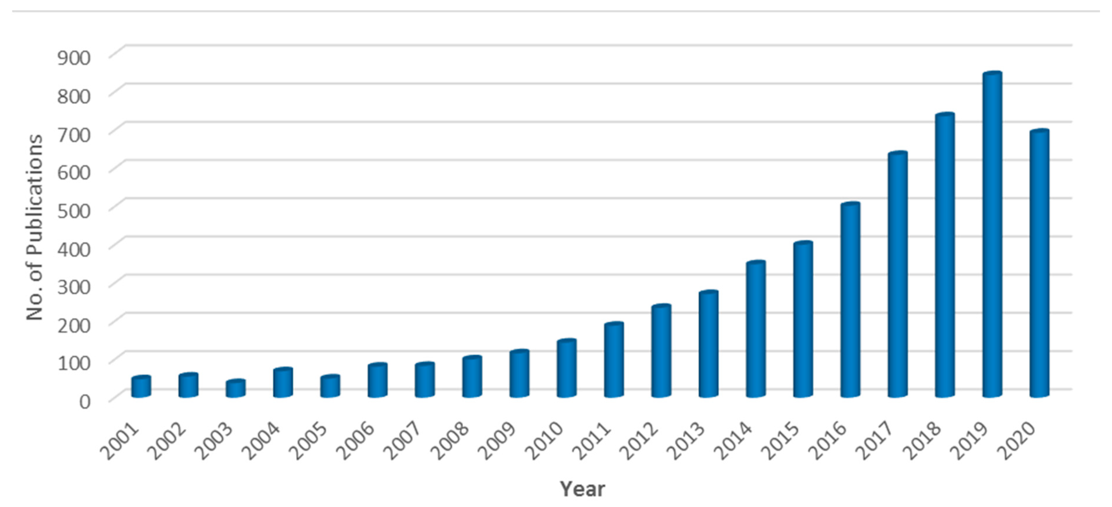
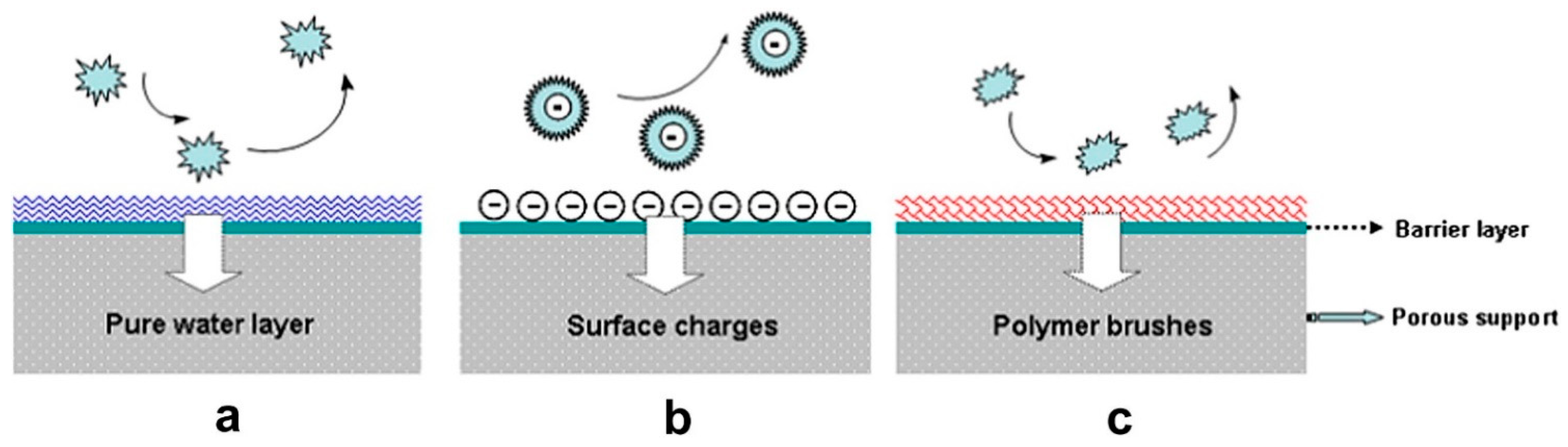
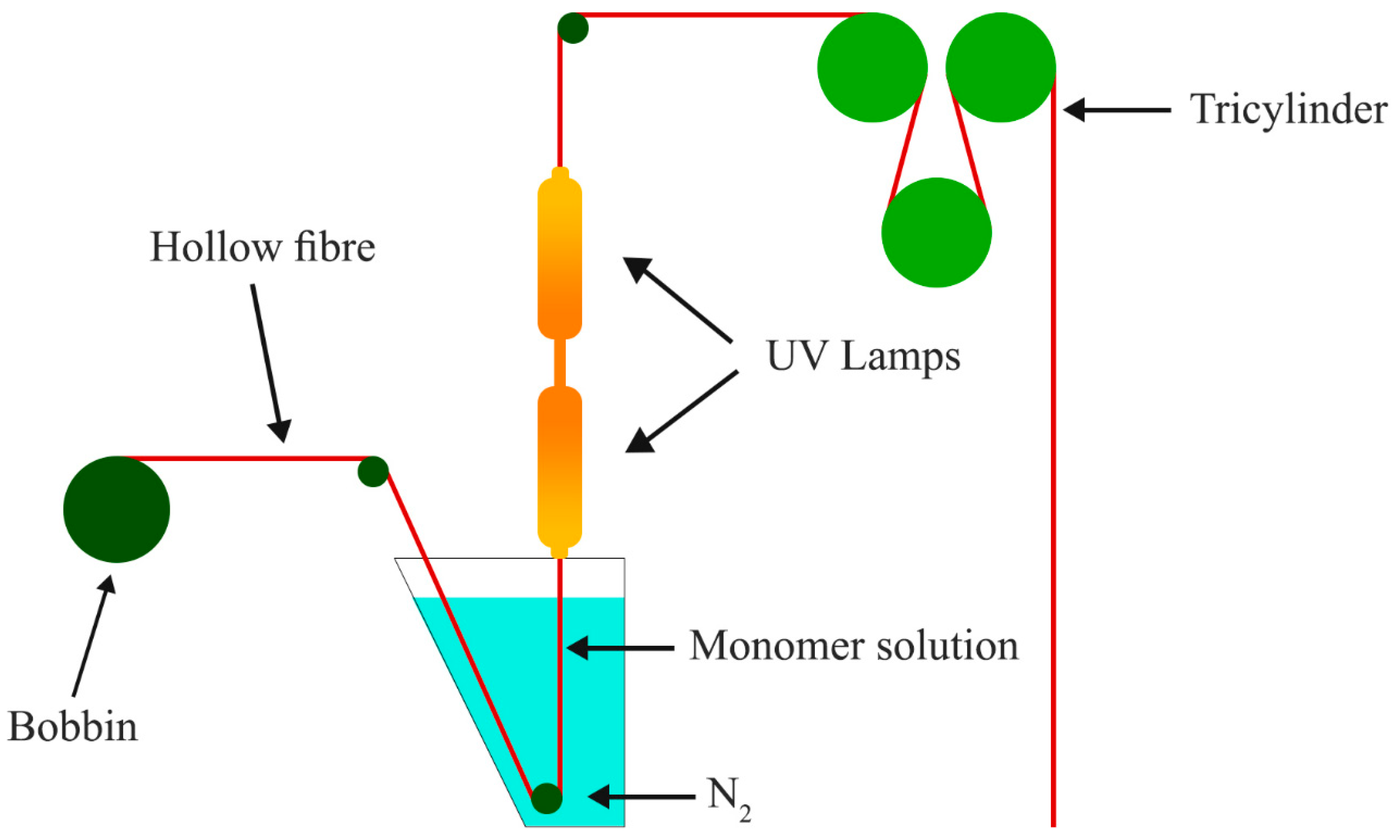
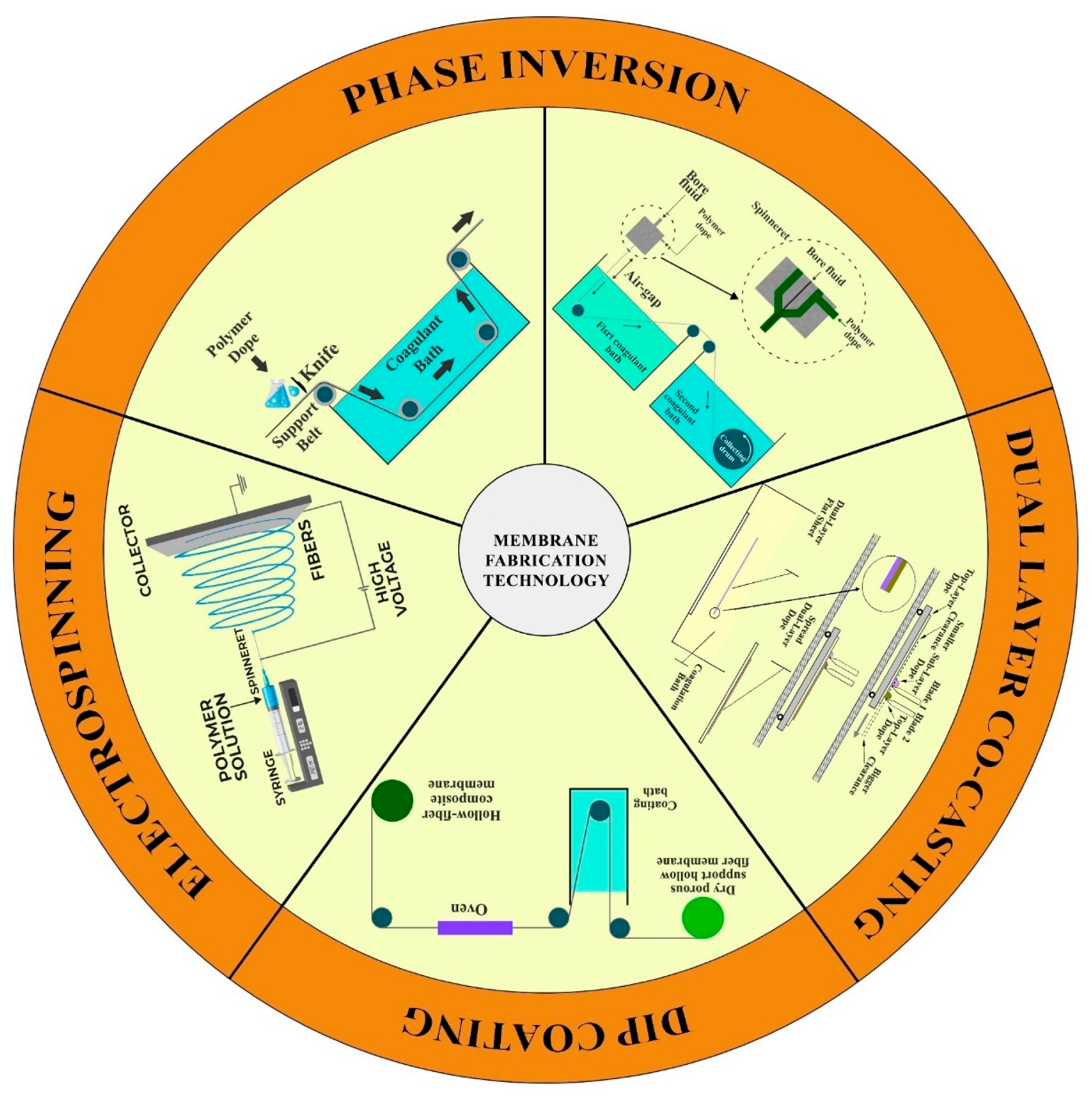
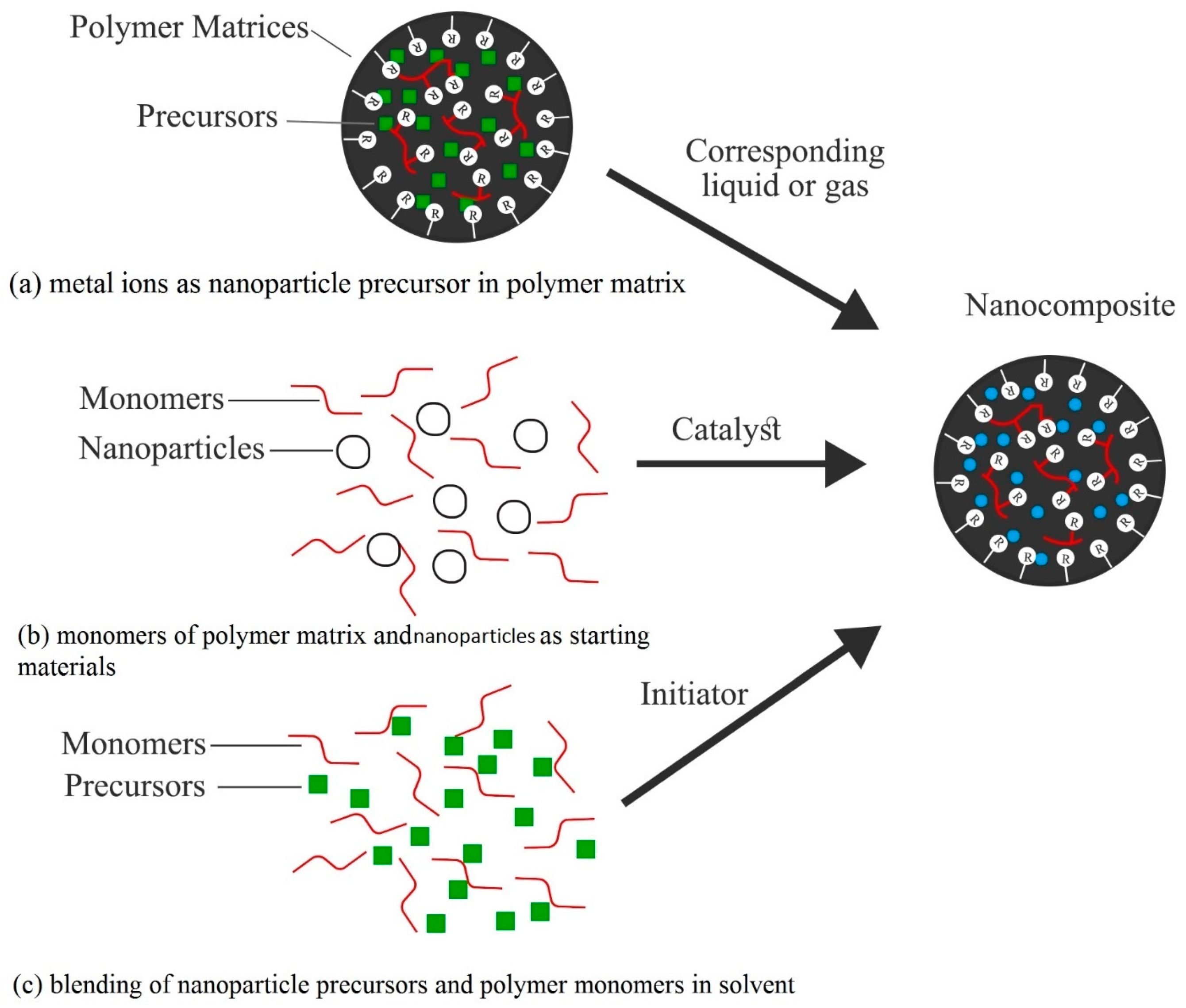
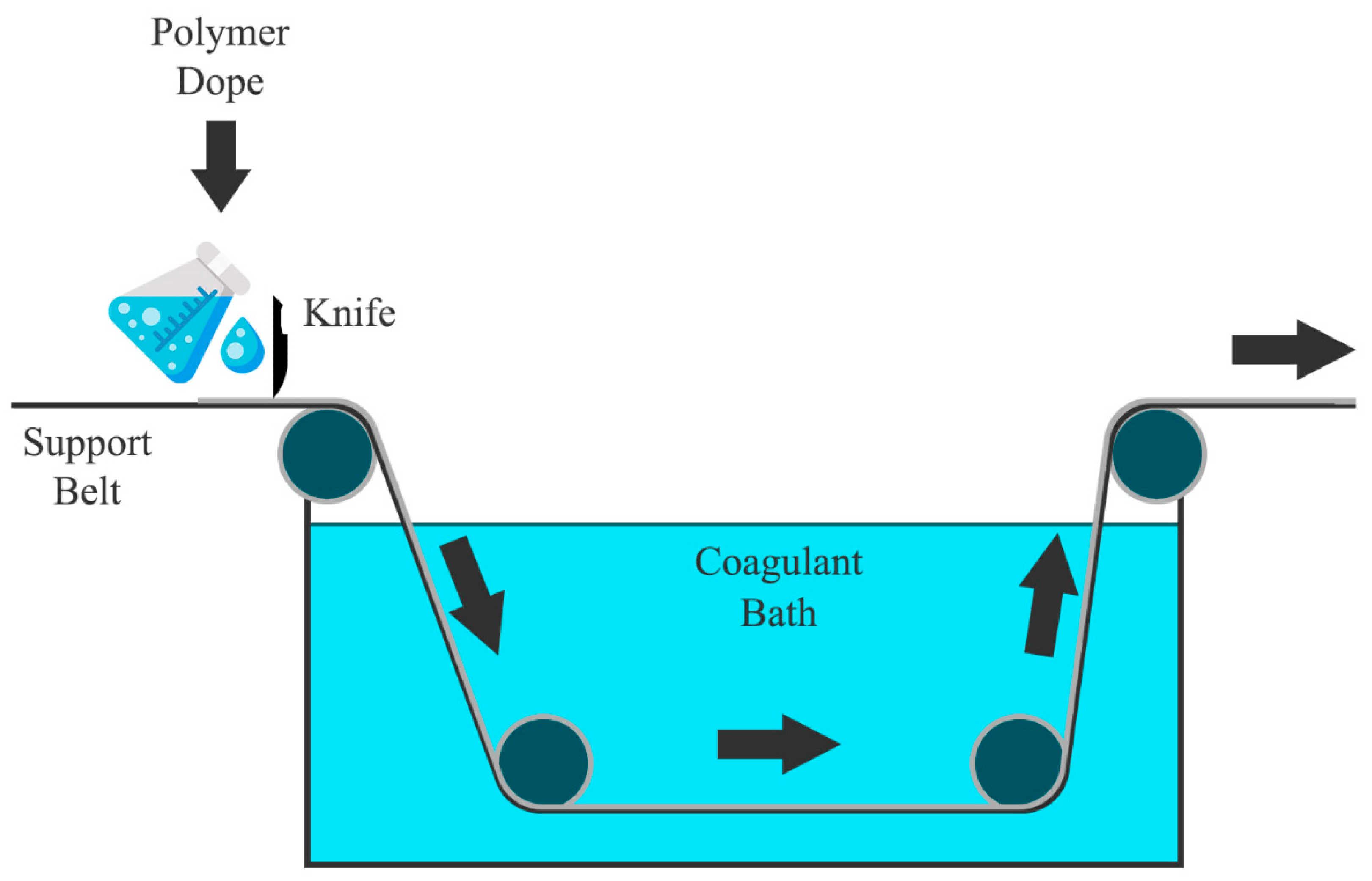
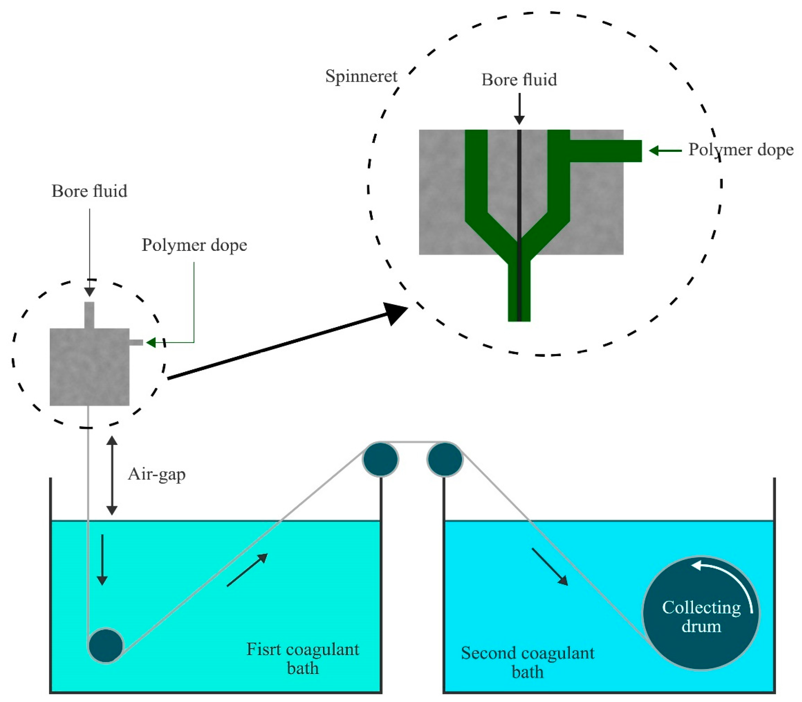
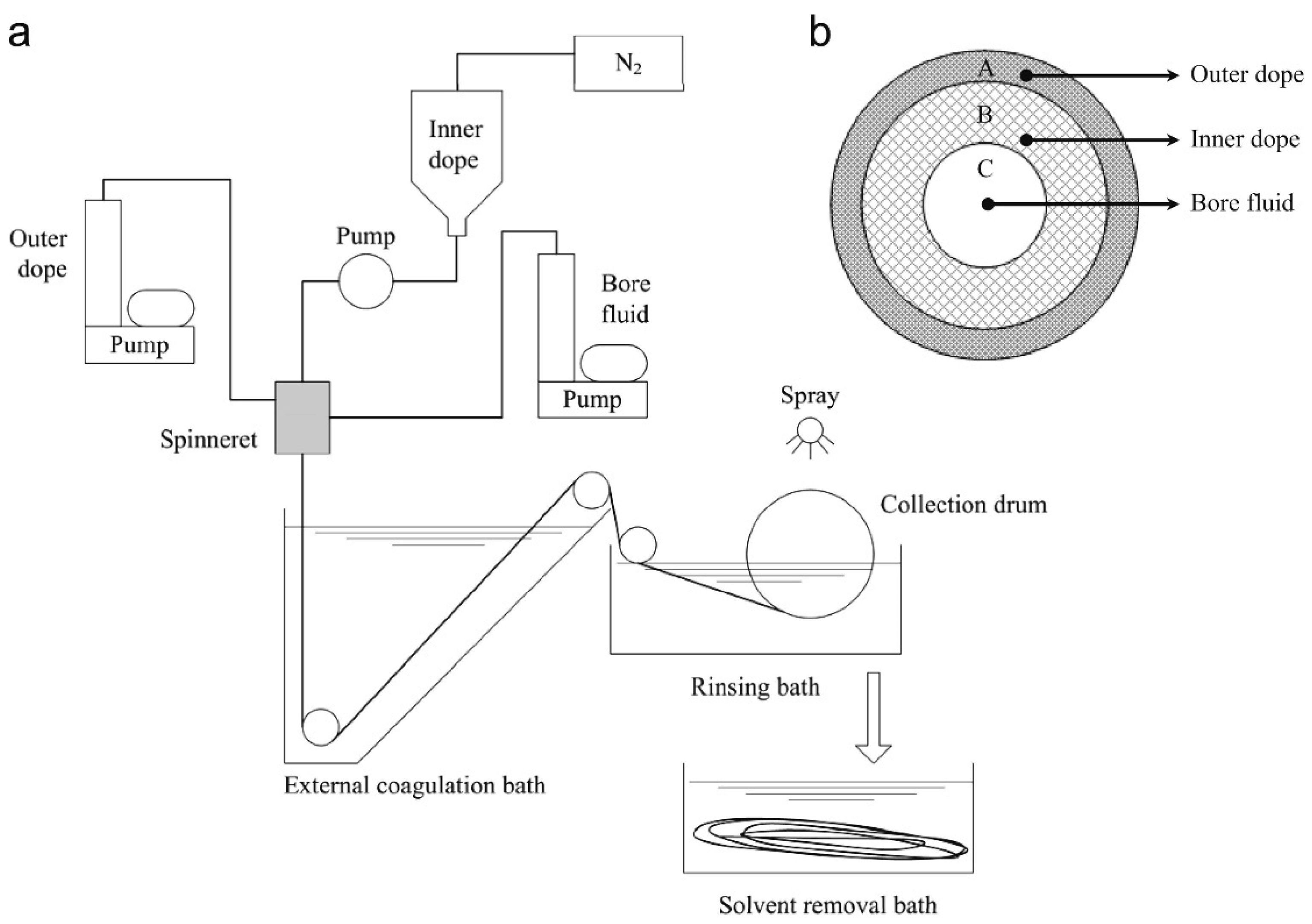
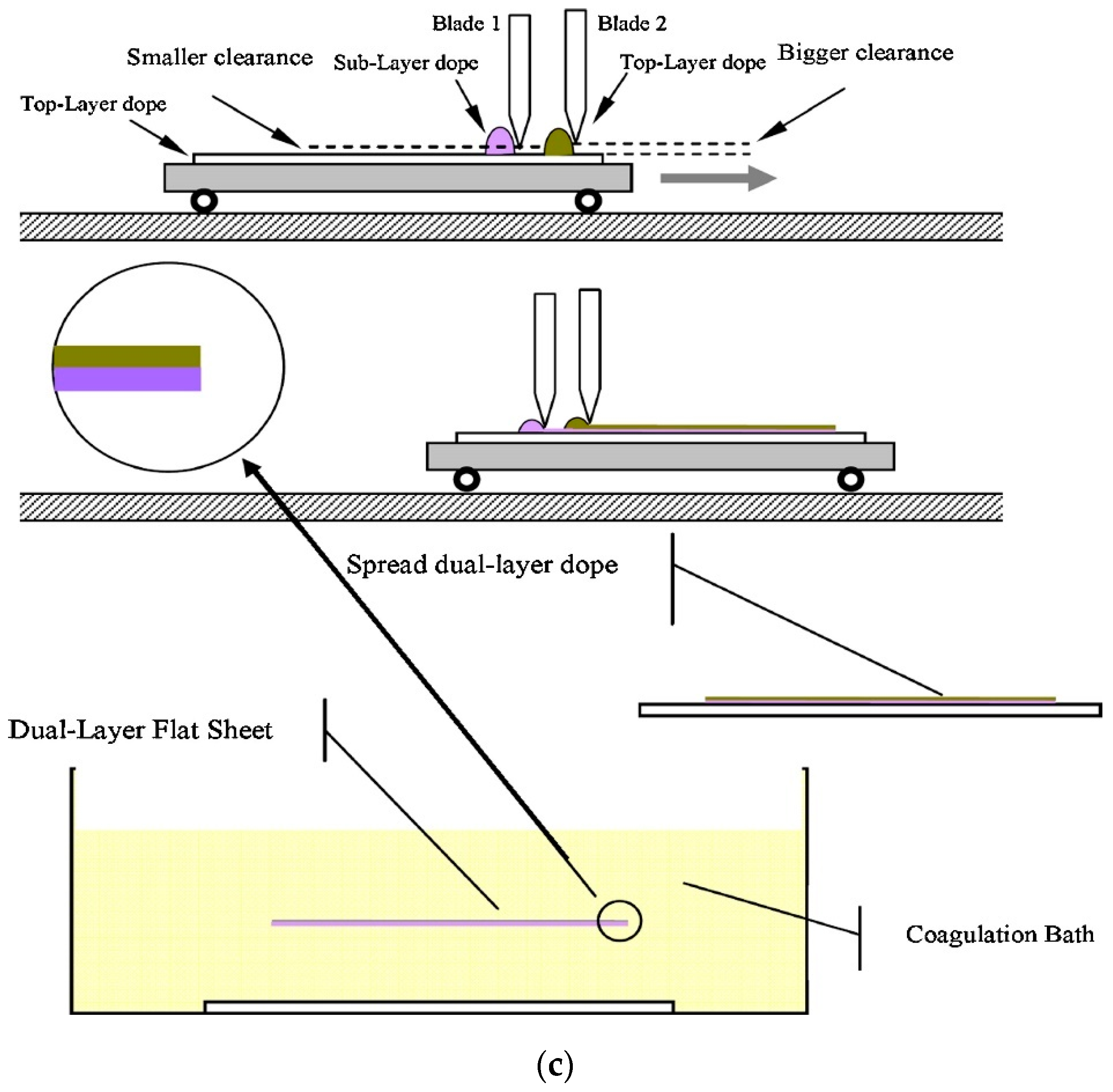
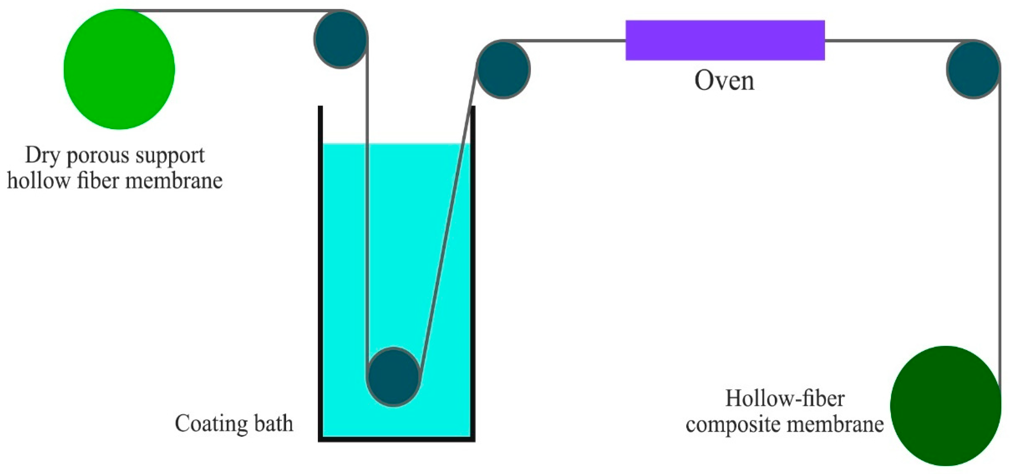
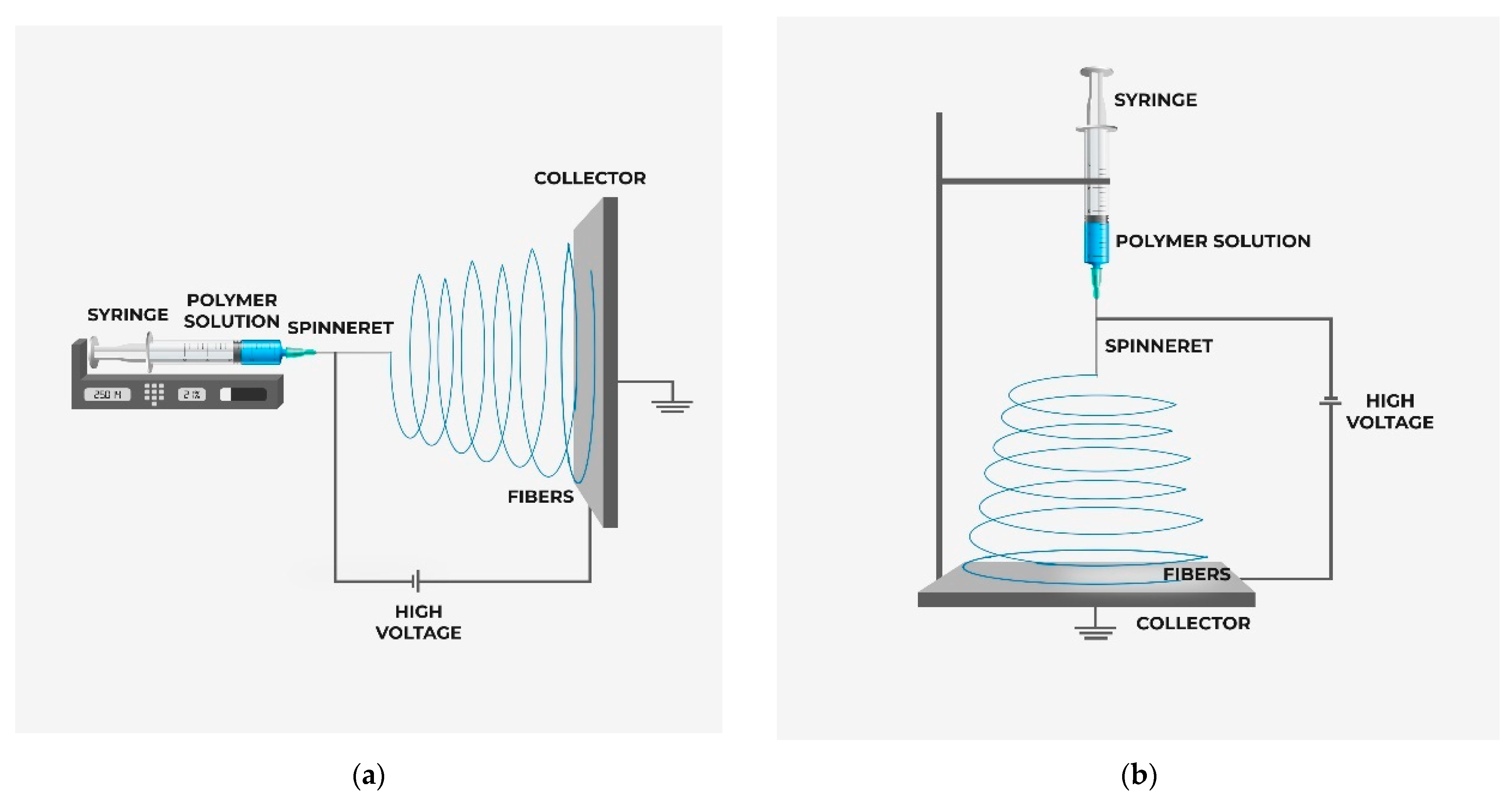
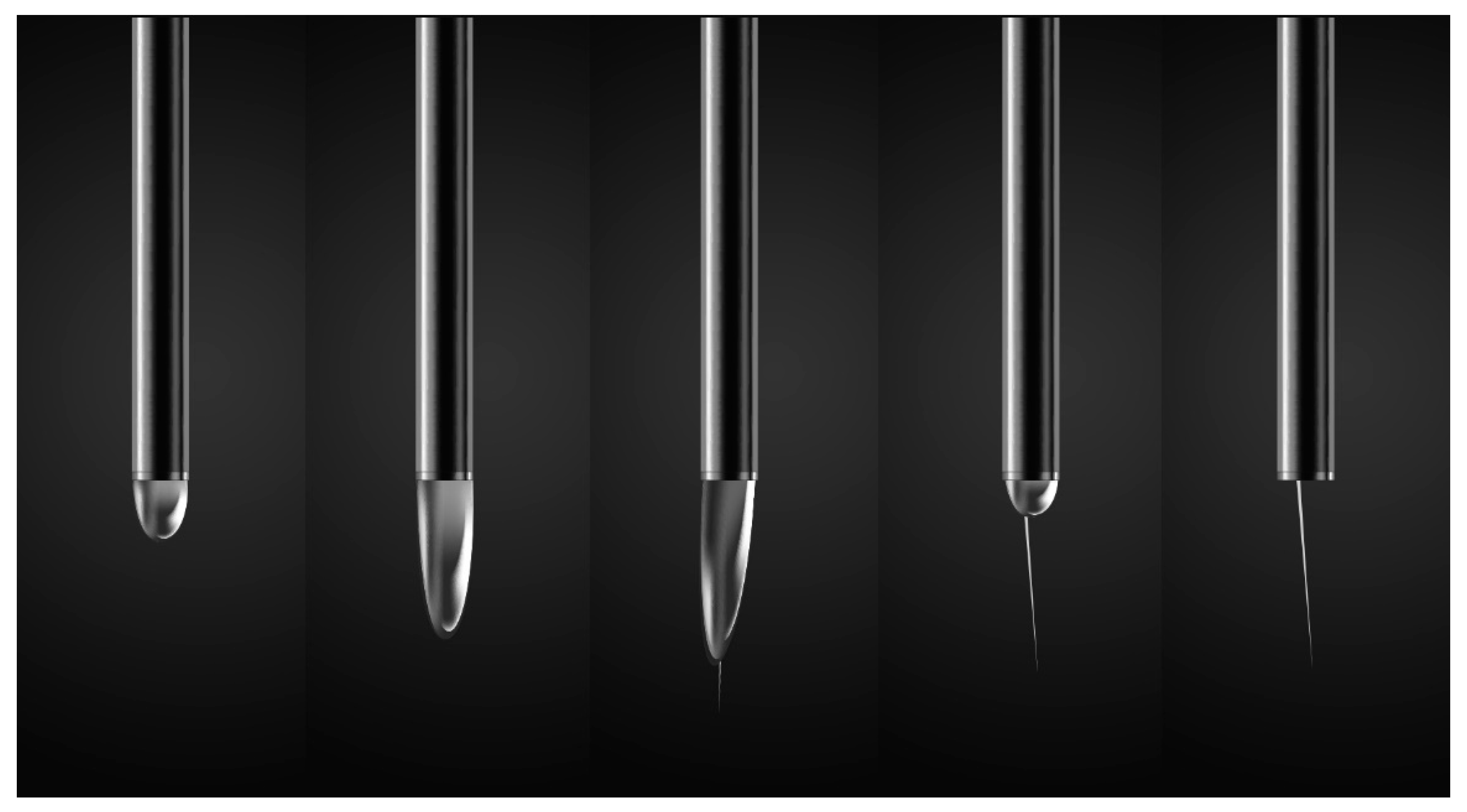
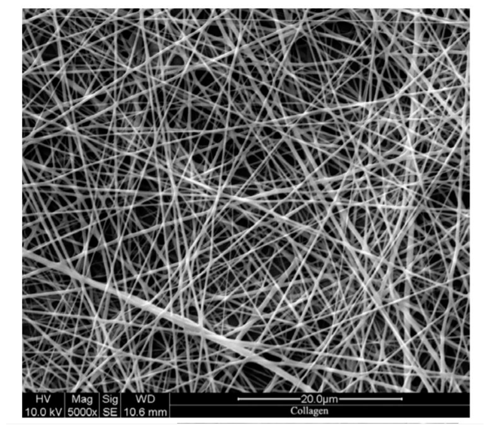
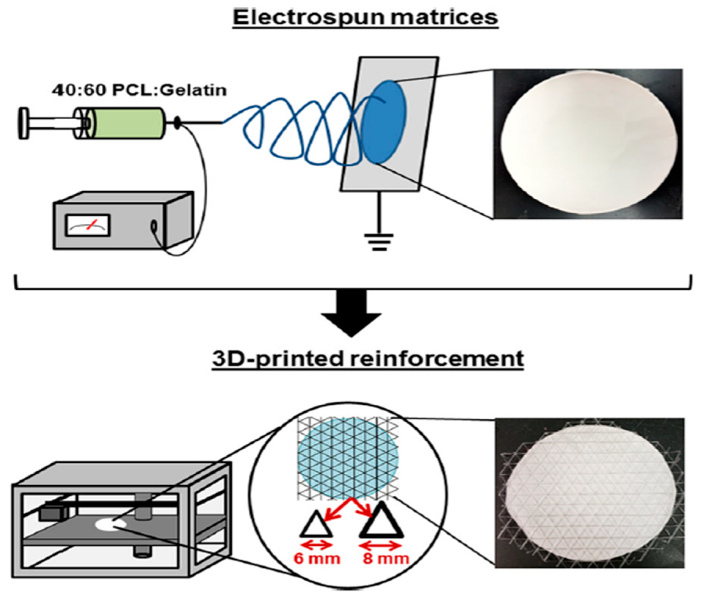
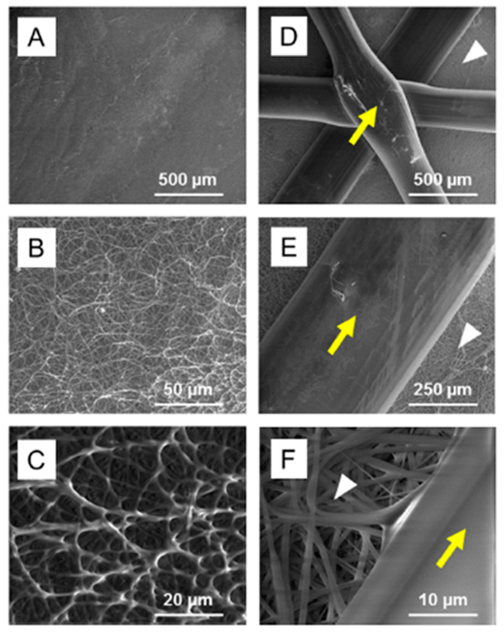
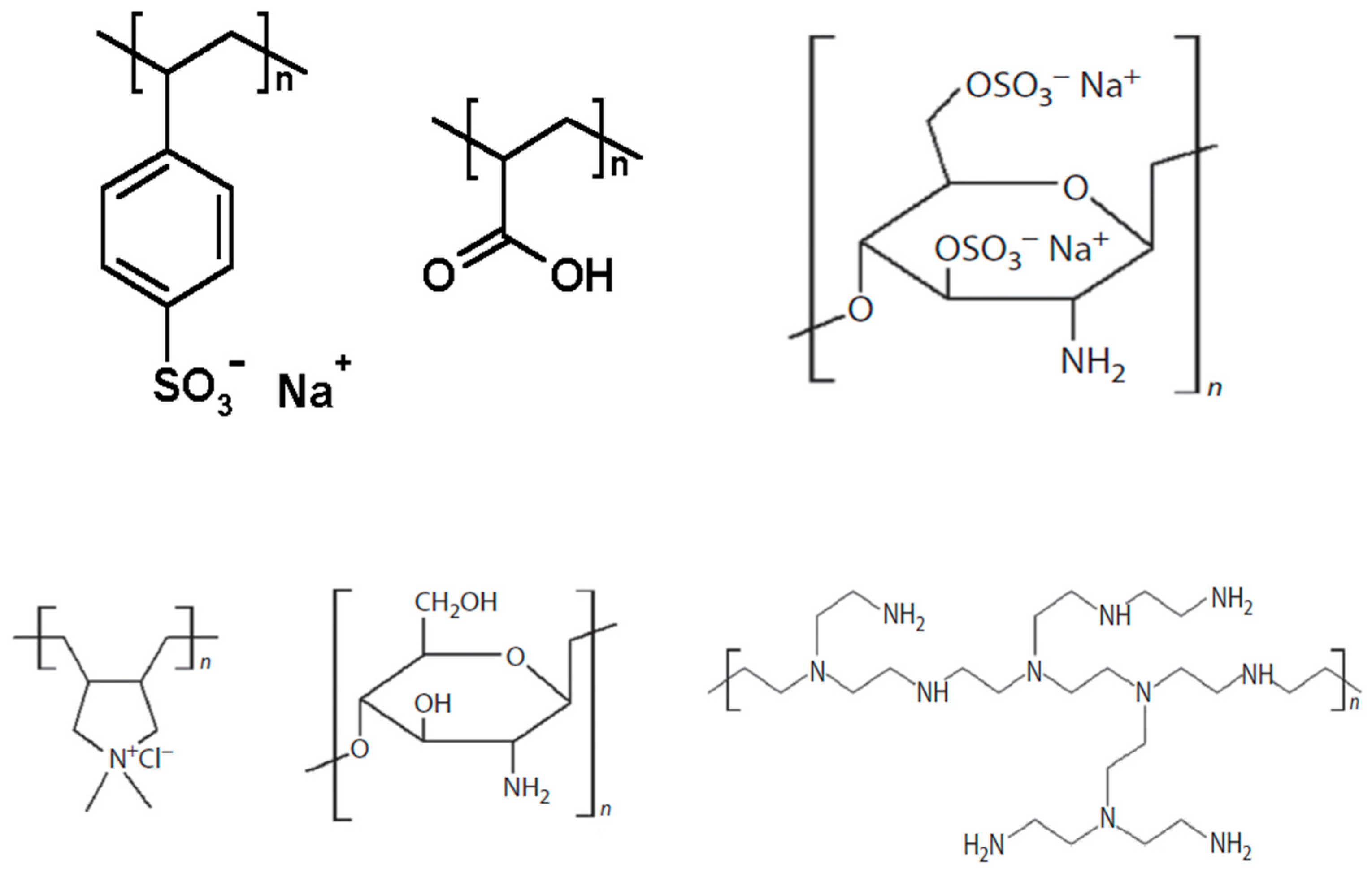
Table 1.
Correlation between the surface roughness of commercial RO/NF membranes and their relative fluxes for the filtration of a 0.05 M NaCl solution containing 200 mg/L silica particles (0.10 µm); pH = 6.8. Flux-decline values determined for 10 L of permeate volume filtered *.
Table 1.
Correlation between the surface roughness of commercial RO/NF membranes and their relative fluxes for the filtration of a 0.05 M NaCl solution containing 200 mg/L silica particles (0.10 µm); pH = 6.8. Flux-decline values determined for 10 L of permeate volume filtered *.
| Membrane Type | Flux Decline, J/J◦, % | Average Roughness, nm | RMS Roughness, nm |
|---|---|---|---|
| Osmonics HL | 13.9 | 10.1 | 12.8 |
| Trisep X-20 | 38.3 | 33.4 | 41.6 |
| Dow NF-70 | 46.9 | 43.3 | 56.5 |
| HydranauticLFC-1 | 49.3 | 52.0 | 67.4 |
* Adapted with permission from [40].
Table 2.
Basic properties of some membranes with their fabrication process.
| Membrane-Fabrication Process | System | Driving Force | Membrane Properties | References |
|---|---|---|---|---|
| Phase inversion | PS/PVP/MXene nanosheets | Solvent and non-solvent interaction (NMP vs. water) | Porosity—79.4% Pore size—29 nm | [157] |
| Phase inversion | Polyimide-GO | Solvent and non-solvent interaction (NMP vs. water) and solvent exchange (2-propanol) | Porosity—65.3% Pore size—0.69 nm Surface Zeta Potential—37.6 MV | [13] |
| Electrospinning | PVDF | Voltage difference | Porosity—88% Electrolyte uptake—440% Conductivity—1.88 mS cm−1 | [158] |
| Phase inversion | PVDF-PAN-SiO2 | Solubility parameter difference, solvent and non-solvent miscibility | Conductivity—3.32 mS cm−1 Electrochemical stability—5 V Electrolyte uptake—246.8% Porosity—78.7% | [159] |
| Graft polymerization | PMMA–g-PE | Grafting PMMA, results in large uptake of electrolyte | Electrolyte uptake—350% Electrochemical stability—5 V Conductivity—1.3 mS cm−1 | [160] |
| Electrospinning | Polyacrylonitrile/polyurethane | Voltage difference | Electrolyte uptake-776.1% Porosity—90.81% Conductivity—2.07 mS cm−1 Bulk resistance—1.2 Ω | [161] |
| Electrospinning | Poly(phthalazinone ether sulfone ketone) | Voltage difference | Electrolyte uptake—1210% Porosity—92% Conductivity—3.79 mS cm−1 Bulk resistance—1.2 Ω | [158] |
| Electrospinning | PS | Voltage difference | Fiber diameter—470 ± 150 nm Pore size—2.1 µm | [162] |
| Electrospinning and dip-coating | PEI/PVDF/x-PEGDA | Voltage difference for electrospun PEI/PVDF membrane and coating of x-PEGDA | Fracture Stress—12.1 MPa Pore size—2.56 μm Porosity—64.6% Electrolyte uptake—235.6% Conductivity—1.38 mS cm−1 | [163] |
| Electrospinning | PEI/PVDF | Voltage difference | Fracture Stress—6.6 MPa Pore size—3.11 μm Porosity—83.5% Electrolyte uptake—492.8% Conductivity—1.03 mS cm−1 | [163] |
| Electrospinning and coating | PE–PI–S | Voltage difference and coating | Porosity—60% Electrolyte uptake—400% Conductivity—1.34 mS cm−1 | [164] |
| Electrospinning | PVDF-HFP | Voltage difference | Porosity—70% Electrolyte uptake—247% Conductivity—3.2 mS cm−1 | [165] |
| Electrospinning | Trilayer (PVDF-HFP)/PVC/(PVDF-HFP) | Voltage difference | Porosity—62% Electrolyte uptake—230% Conductivity—1.58 mS cm−1 | [165] |
| Electrospinning | PVDF/SiO2 | Voltage difference | Porosity–85% Electrolyte uptake—646% Conductivity—7.47 mS cm−1 | [166] |
| Electrospinning | Polyamic acid | Voltage difference | Pore size—800 nm Porosity—65.9% Electrolyte uptake—559% | [167] |
| Electrospinning | SiO2/nylon 6,6 | Voltage difference | Porosity—77% Electrolyte uptake—360% Conductivity—3.8 mS cm−1 | [168] |
| Electrospinning | PVDF-HFP/PEG/PEGDMA | Voltage difference | Electrolyte uptake—212% Porosity—71% Bulk resistance—0.94 Ω | [169] |
Table 3.
Merits and disadvantages of MMM fabrication processes.
| MMM Fabrication Process | Merits | Disadvantages | References |
|---|---|---|---|
| Phase inversion |
|
| [170,171,172] |
| Interfacial polymerization |
|
| [173] |
| Electrospinning |
|
| [174] |
Publisher’s Note: MDPI stays neutral with regard to jurisdictional claims in published maps and institutional affiliations. |
© 2021 by the authors. Licensee MDPI, Basel, Switzerland. This article is an open access article distributed under the terms and conditions of the Creative Commons Attribution (CC BY) license (https://creativecommons.org/licenses/by/4.0/).
Share and Cite
MDPI and ACS Style
Siddique, T.; Dutta, N.K.; Choudhury, N.R. Mixed-Matrix Membrane Fabrication for Water Treatment. Membranes 2021, 11, 557. https://0-doi-org.brum.beds.ac.uk/10.3390/membranes11080557
AMA Style
Siddique T, Dutta NK, Choudhury NR. Mixed-Matrix Membrane Fabrication for Water Treatment. Membranes. 2021; 11(8):557. https://0-doi-org.brum.beds.ac.uk/10.3390/membranes11080557
Chicago/Turabian StyleSiddique, Tawsif, Naba K. Dutta, and Namita Roy Choudhury. 2021. "Mixed-Matrix Membrane Fabrication for Water Treatment" Membranes 11, no. 8: 557. https://0-doi-org.brum.beds.ac.uk/10.3390/membranes11080557
Note that from the first issue of 2016, this journal uses article numbers instead of page numbers. See further details here.