1. Introduction
In Ningxia, Gansu, Shaanxi and other regions of China, the plastic film mulching potato planter are widely used. The cultivated land in these areas is mainly hills and is mountainous and there are a lot of planters working on sloping fields. The main function of mulching is to maintain warmth and moisture levels, to promote the rapid germination of seeds and to achieve the purpose of increasing yield and reducing the growth period. The effect of covering soil is an important evaluation of the quality of mulching and there is a large impact on the volume of covering soil on both sides of mulch in sloping fields. Furthermore, it is necessary to make tentative adjustments based on experience and it is difficult to achieve best the covering quality. Therefore, it is of great significance to develop a soil covering device for potato planters that achieve the same volume of covering soil on both sides in sloping fields [
1,
2].
The research on the soil covering device of potato planter has been conducted earlier in foreign countries with advanced technology and high reliability. The typical equipment includes GL series potato planter produced by GRIMME in Germany and the LK series potato planter produced by STRUIK in Netherlands. These machines have high efficiency and quality, which are suitable for areas with large-scale fields rather than hills and mountainous areas. Recently, the development of potato planting machinery technology and equipment in China has become rapid. The potato planter was designed and tested and includes the sowing depth control device and wide ridge pattern suitable planter [
3,
4,
5]. Liu and other scholars designed the film mulching potato planter, which applied to rice, quinoa, potato and so on [
6,
7,
8]. Chen and other scholars put forward film mulching technology, soil conveying technology, etc., which provide technical support for the research and development of potato planters [
9,
10,
11,
12,
13]. The study on the optimization of working parameters and improvement of the design structure of the potato planter and mulching device was conducted by Xin and others [
14,
15,
16,
17,
18]. These technologies and equipment have been experimented and verified to basically suit the requirements of field working. When working on flat fields, the quality of covering soil is higher; however, in the sloping field, there will be inconsistencies in the volume of covering soil on both sides and the stability of cover will decrease. The covering quality is reduced, which is not conducive to heat and moisture preservation and will affect the high yield and premature delivery of potatoes [
19,
20,
21].
Therefore, a soil covering device was designed to improve seeding quality by linkage and differential adjustments of the disc separately and the field experiment was completed to verify the performance of soil covering device, which takes the stability coefficient and uniformity coefficient of the volume of covering soil as factors.
2. Material and Methods
2.1. The Device of Experiment
As shown in
Figure 1, the potato planter mainly includes fertilizer box, seeder, seed box, ridging machine, laminating machine and soil covering device. The prototype takes the Qingdao HONGZHU potato planter and the planting method utilizes double rows on a ridge. The fertilizer from the fertilizer box is applied to the middle position of the ridge and planted on both sides of the ridge.
A spoon-chain seeder metering device is used to take out the lumpy potato seeds from the seed box and to shake the excess potato seeds back into the seed box under the action of the vibrating seed cleaning device. The ridging machine trims the ridge shape according to the set value. The laminating machine covers the film on the ridge surface and the packer wheel and soil covering machine takes the soil covering both sides of film.
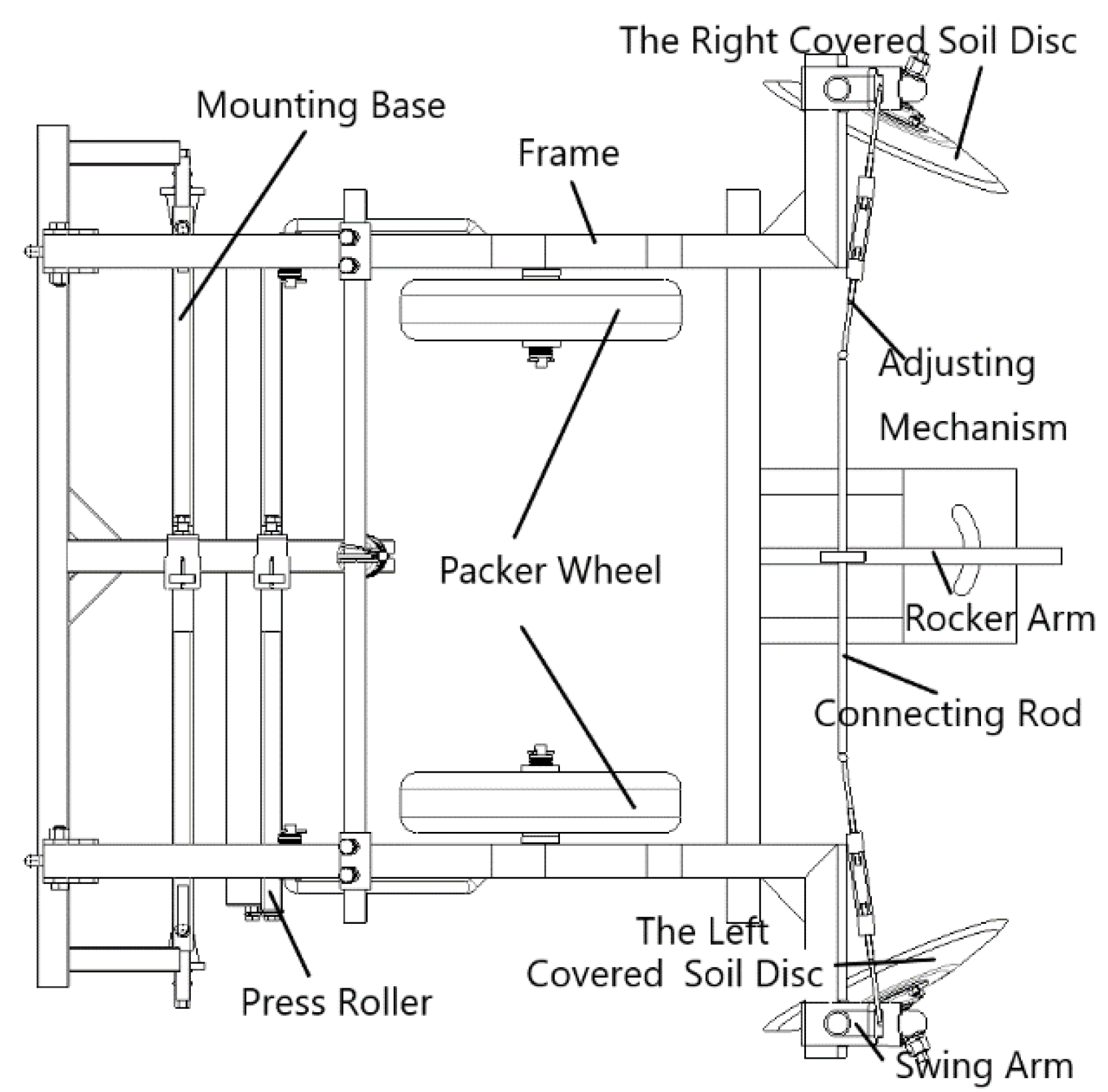
Figure 2 shows the structure diagram of soil covering device and the device mainly includes covered soil discs, adjusting mechanism, frame and so on. The distance between the selection centers of the covered soil discs on both sides is adjustable from 1100 to 1500 mm, which can suit the work of 0.8–1.2 m width film and the maximum adjustment of the rotation angle of the covering disc is 75°.
The tractor pulls the device forward and the press roller presses the film on the ridge surface. The packer wheel then presses down the film on the ridge side and the covered soil disc pushes the loose soil of the furrow to the film on the ridge side to complete the entire film.
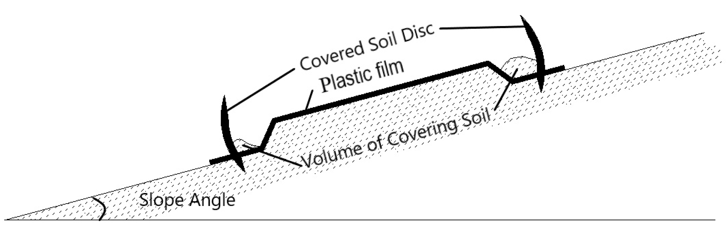
The uniformity and stability of the volume of covering soil is an important factor for the quality of the soil covering device. When working on flat ground, the angle of the covered soil discs on both sides is generally required to be consistent and the covering quality can basically meet the operation requirements. However, as shown in
Figure 3, when working on sloping field, the volume of soil on both sides will be affected by the slope angle and the amount of soil on the upper side is much larger than that on the lower side. Therefore, it is necessary to adjust the angle of the covered soil disc to keep the volume of covering soil on both sides consistent.
2.2. The Data Analysis
The main function of the adjustment mechanism is to adjust the angle of the soil covering discs on both sides to improve the mulching quality.
As shown in
Figure 4, the adjustment mechanism mainly includes the covered soil disks on both sides, the rocker arm, the four-bar mechanism composing the frame, the connecting rod and the swing arm. The connecting rod adopts a two-way screw structure and, by rotating the middle nut, the length of the connecting rod can be changed and the angle of the discs on both sides can be adjusted in linkage under the action of the four-bar mechanism. The two sides of the connecting rod and the swing arm are correspondingly connected by hinged shafts. On the other hand, the rocker arm can rotate around the end point. During the rotation, the connecting rod will rotate synchronously to realize the differential adjustment of the covered soil disc. The angles α and β of both side discs are correspondingly related to the mechanism parameters of the four-bar mechanism.
Firstly, the model equations of the angle and related parameters are established through a theoretical calculation and then the corresponding relationships between different slope angles and adjustments are obtained based on the test data.
(1) The linkage adjustment
The intercept of the two-way nut screw is
p, the length of the swing arm is
Ls and
LLs, respectively. When the function of the hinge axis is not considered, the Equation (1) exists and is described as follows:
where
n is number of rotations and ∆
a is the turning distance of the end of the swing arm in mm.
(2) The differential adjustment
When the four-bar mechanism is composed of the frame, the connecting rod and the swing arm is arranged in a parallel. If the rocker arm is deflected counterclockwise and the angle is
γ, then there exists the following equation:
where
are the initial angles of the discs on both sides.
When the four-bar mechanism is not arranged in a parallel, the calculation method of steering trapezoid is referred to and described in the following.
where
is the initial bottom angle of trapezoidal four-bar mechanism in degrees and
L is the length of the connecting rod (short side) in mm.
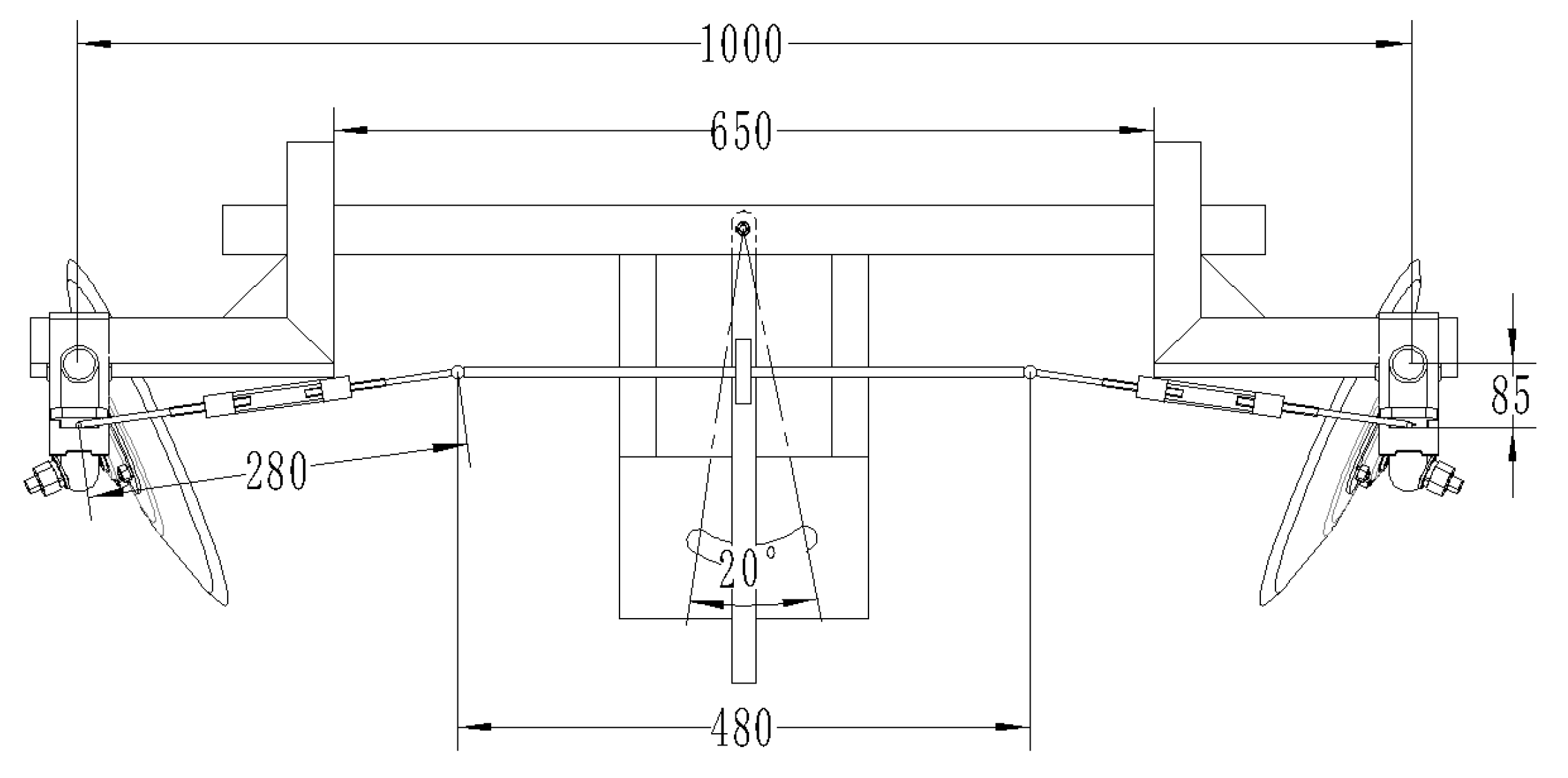
The size of adjusting mechanism in potato planter is shown in
Figure 5. The initial bottom angle of the trapezoidal four-bar mechanism is determined by the length of the swing arm, the intercept of the nut screw and the number of rotations. By using the Equation (3), the rotation angle of the swing arm can be quantified. It is also necessary to calibrate the inclination requirements of the upper and lower soil covering discs according to different slope angles. So far, the design parameters of the four-bar mechanism can be obtained.
The purpose of the experiment is to calibrate the volume of covered soil under different angles of the disc. On the other hand, when the angles of the discs on both sides are inconsistent, the experiment detects the difference and stability of the volume of covered soil on both sides. The flat fields have been used to complete the field experiment by using the stability coefficient of the difference in the volume of covered soil on both sides to evaluate the quality of the covering soil.
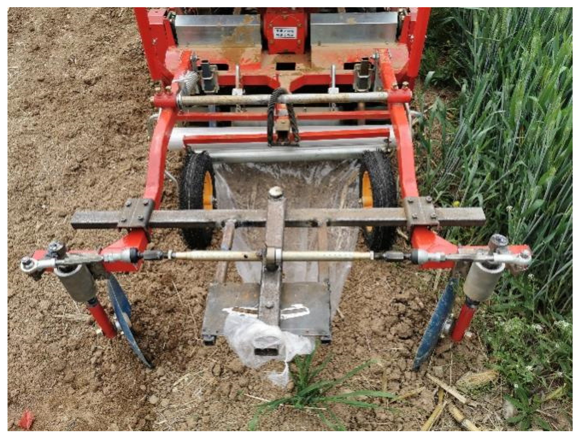
The potato planter used in the experiment adopts a self-made soil covering device with adjusting mechanism, which based on the HONGZHU-1.2 large ridge double-row planter. The adjusting mechanism was shown in
Figure 6 and the mulch uses ordinary plastic film with a thickness of 0.0012 mm and a width of 1.2 m.
The tractor uses DONGFANGHONG-504 from LUOTUO (about 36.8 kW) and the operating speed is about 3.6 km/h.
2.3. The Method of Experiment
On 9 April 2020 at the Northwest A&F University test farm, the operation performance test of soil covering device was carried out. The field of experiment has a length of 110 m and a width of 10 m. It is a typical columbine soil condition. Moreover, corn was planted in the first stubble and two rotary tillage treatments were carried out after harvest. The soil moisture content of the cultivated layer (5–10 cm) is 18.5%(w.b.) and the average firmness of soil is 2.05 MPa. The soil covering disc adopts a concave disc with a diameter of 45 cm and the depth of the disc is adaptively adjusted by spring preloading and force adjustment, the measured data shows that the average depth of the disc into the soil is 14.27 mm.
In order to calibrate the volume of soil covering under the adjustment of different disc angles, five points were randomly selected to measure in each level and 30°, 45° and 60°, respectively, were used as linkage adjustment angles of the covered soil disc. Moreover, the angles of the covering discs on both sides are selected to be 30° and 60°, respectively, as the difference adjustment. The
Table 1 shows the method for adjusting the angle of the covered soil discs on both sides. The sampling points were selected according to the five-point method and randomly selected on a ridge in stable working area as the sampling points. Repeat three ridge operations under the same angle of discs and take the average for calculation.
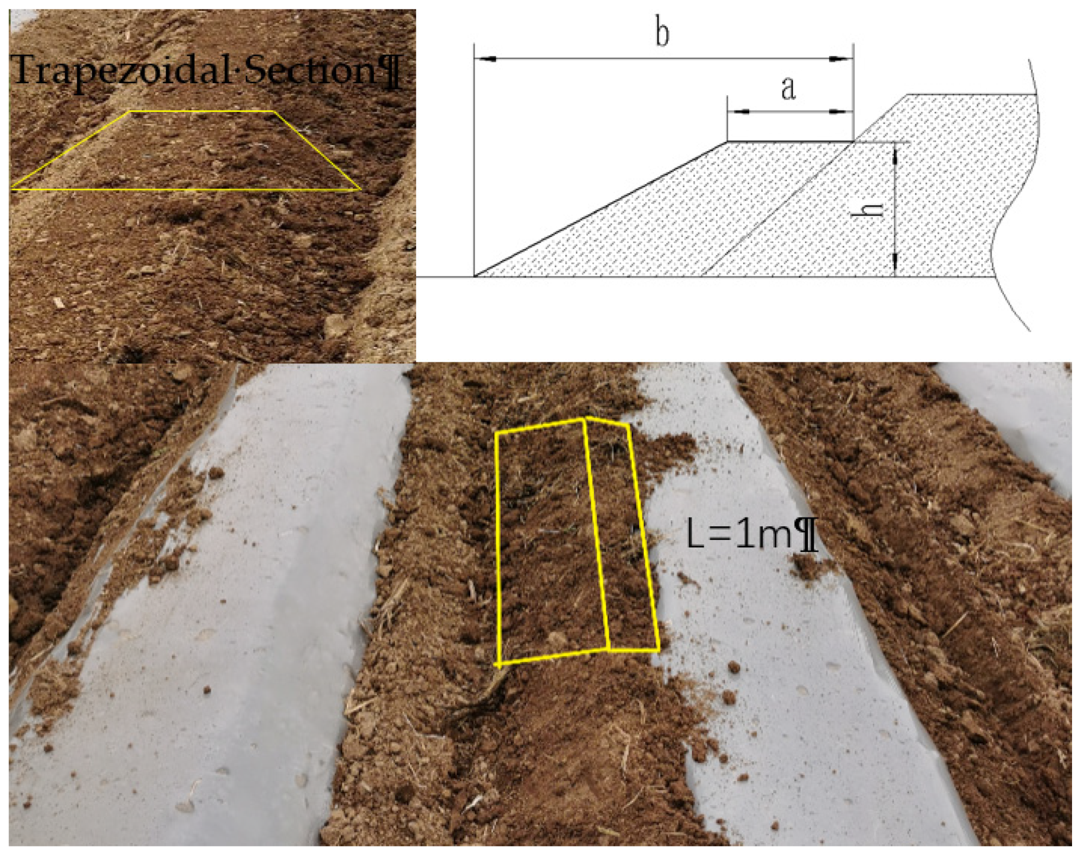
As shown in
Figure 7, the volume of covered soil is calculated by the area of the section and the length of the sampling (take 1 m), as shown in Equation (3) as follows:
where V is the volume of covered soil, m
3; a is the length of the section, m;
b is the width of the section, m;
h is the height of the section, m;
l is the length of the sampling, m.
Therefore, the main measurement factors include the width, height and length of the covered soil section. Considering that the ridge structure is relatively stable (the slope angle is about 45°), the area of the covering soil section can be formed by subtracting the area of an isosceles right triangle from a right-angled trapezoid for which the side lengths are a, b and h.
The area of the covering soil section can be formed by a right-angled trapezoid with width, length and height as three sides and minus the area of the isosceles right triangle with the height as the right side.
The stability coefficient and uniformity of the volume of covered soil are used as indicators to investigate the feasibility of the differential adjustment and linkage adjustment. Refer to the “uniformity determination” and “stability determination” methods in the test method of the quality evaluation technical specification for fertilization machinery (NY/T 1003-2006) for calculation. The uniformity mainly measures the uniformity coefficient of the volume of covered soil. When the angles of the soil covering discs on both sides are different, the uniformity coefficient of each side is measured separately, which can characterize the feasibility of the differential adjustment. The stability mainly measures the stability coefficient of the volume of covered soil. When the angle of the soil covering discs on both sides are same, the stability coefficient of each side is measured separately, which can characterize the stability of the linkage adjustment.
2.3.1. The Calculation of Uniformity Coefficient
The uniformity coefficient of the volume of covered soil includes standard deviation and the variation coefficient. Before the experiment, the parameters of the soil covering plate were adjusted and the tractor was moving forward steadily at an average speed of 3.6 km/h. Five points were randomly selected in the test area and the section parameters of the covered soil on both sides were correspondingly measured. The volume of covered soil was calculated according to the above method and, according to Equation (4), the standard deviation and the variation coefficient of the uniformity on both sides were calculated as follows:
where
x is average volume of covered soil, m
3;
is volume of covered soil of the point, m
3;
S is the standard deviation of the uniformity;
V is the variation coefficient of the uniformity, %;
n is the number of measuring points, (
n = 5).
2.3.2. The Calculation of Stability Coefficient
The stability coefficient of the volume of covered soil includes the standard deviation and the variation coefficient. The test method is the same as the calculation of the uniformity coefficient. Refer to the calculation in Equation (3), where, x is average value of the difference in the volume of covered soil on both sides, m3; is difference of volume of covered soil on both sides of the point, m3; S is the standard deviation of the stability; V is the variation coefficient of the stability, %; n is the number of measuring points, (n = 5).
3. Results and Discussion
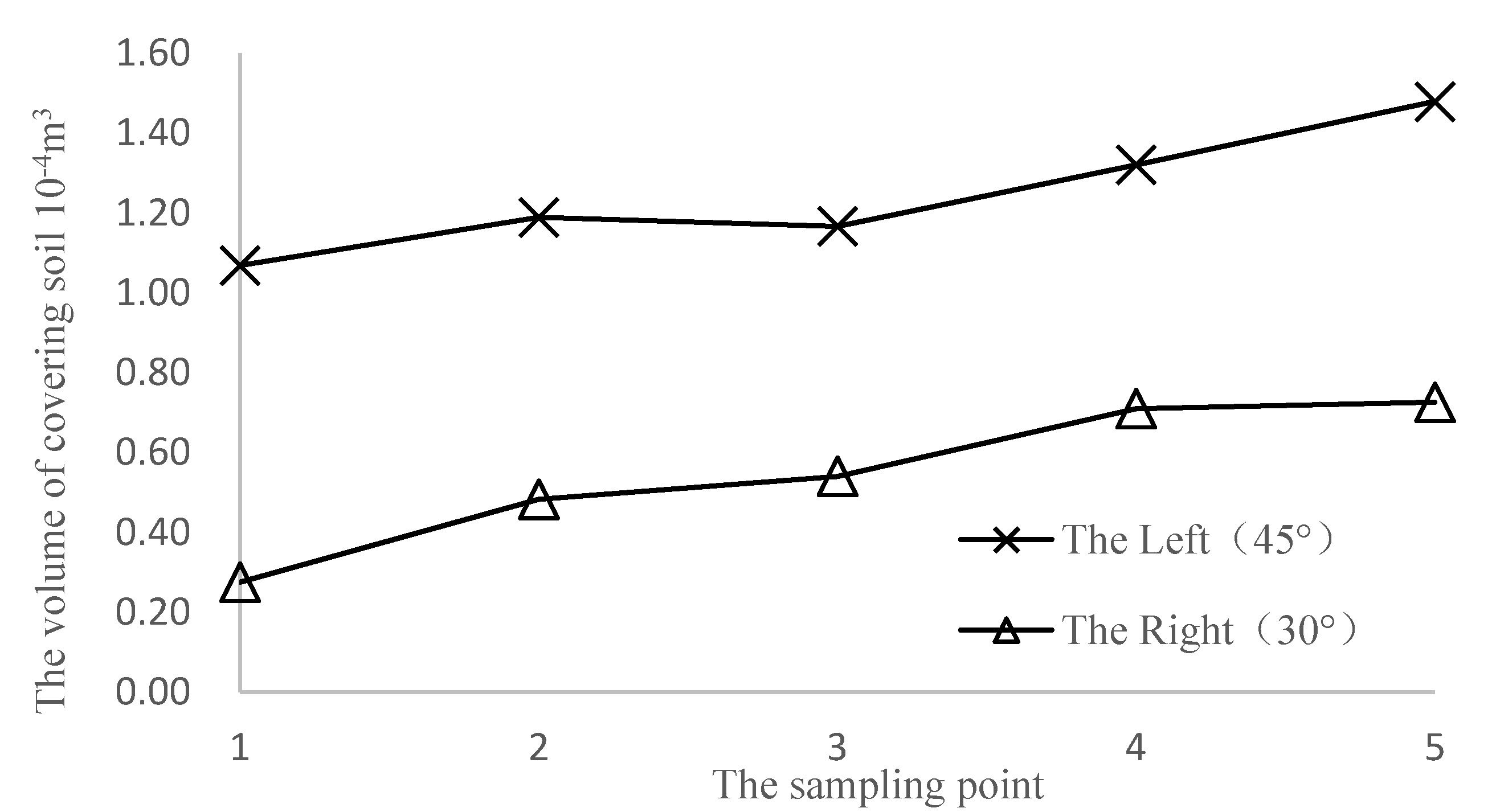
As shown in
Figure 8, when the angles of the soil covering discs on both sides are 30° and 45°, the volume of covered soil at the measuring points is 0.28–0.73 × 10
−4 m
3 and 1.07–1.48 × 10
−4 m
3, respectively. The volume of covered soil is quite different between both the angles of discs, but the difference is relatively close at different points. The maximum difference of 0.79 × 10
−4 m
3 appears at the first point and the minimum difference of 0.61 × 10
−4 m
3 appears at the fourth point. When the angle of the covering disc is 30°, the average volume of covered soil is 0.55 × 10
−4 m
3 and when the angle of the covering disc is 45°, the average volume is 1.12 × 10
−4 m
3.
It shows that the volume of covered soil is different at each point but, at the same point, there is a relatively fixed difference of the soil covering discs on both sides.
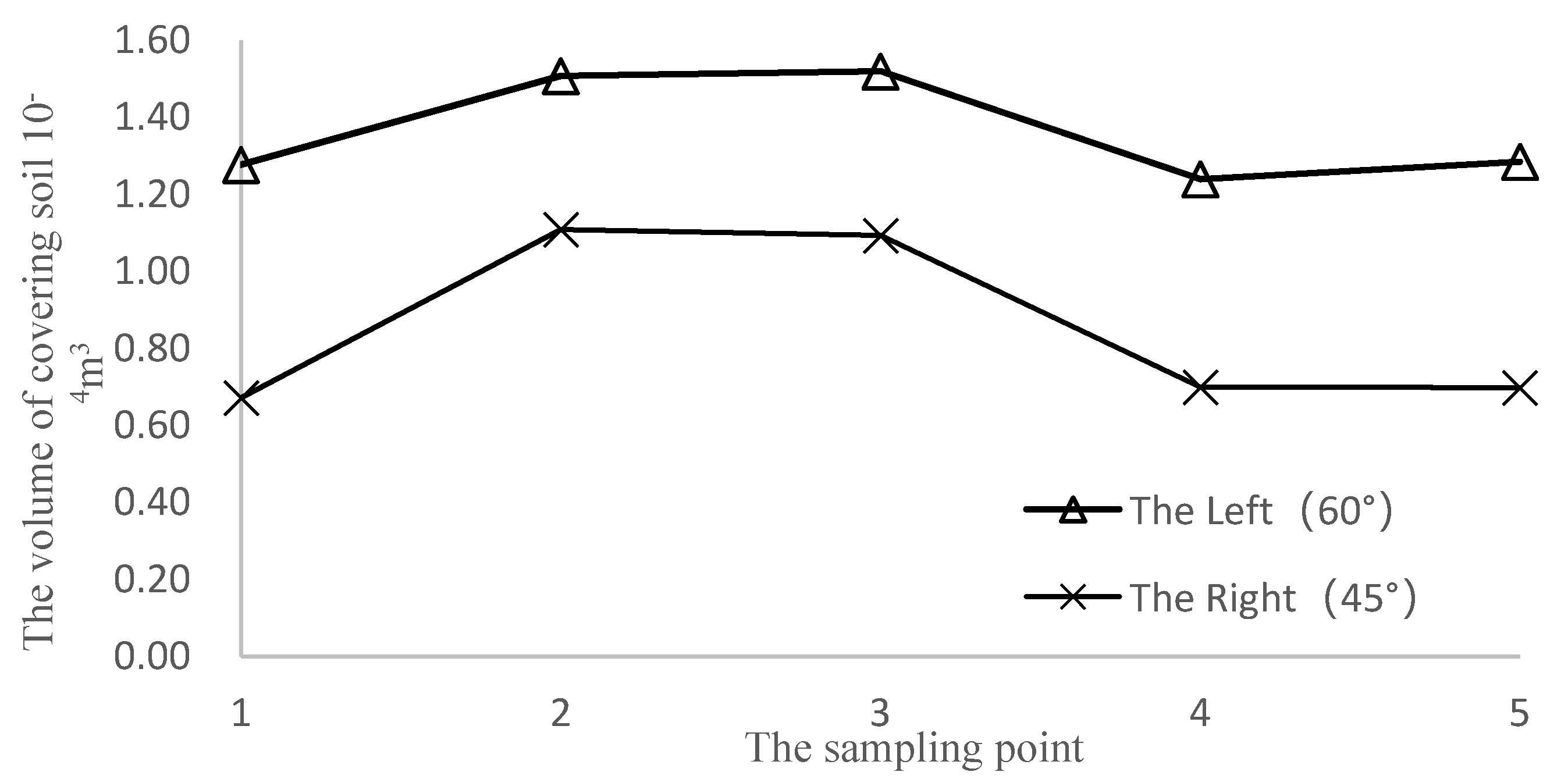
As shown in
Figure 9, when the angles of the soil covering discs on both sides are 45° and 60°, the volume of covered soil at the measuring points is 0.67–1.11 × 10
−4 m
3 and 1.24–1.52 × 10
−4 m
3, respectively. The maximum difference of 0.60 × 10
−4 m
3 appears at the first point and the minimum difference of 0.40 × 10
−4 m
3 appears at the second point. When the angle of the covering disc is 45°, the volume of covered soil is 0.85 × 10
−4 m
3 and when the angle of the covering disc is 60°, the average volume is 1.37 × 10
−4 m
3.
When the angle of covering disc is 45°, the volume of covered soil is about 31% smaller than that of the previous group. The reason may be that there will be some interference between adjacent rows during the operation. Specifically, the engaged previous row of soil covering will reduce the amount of soil in the ditch and, as a result, the amount of floating soil on the adjacent side becomes less while the volume of covered soil is reduced.
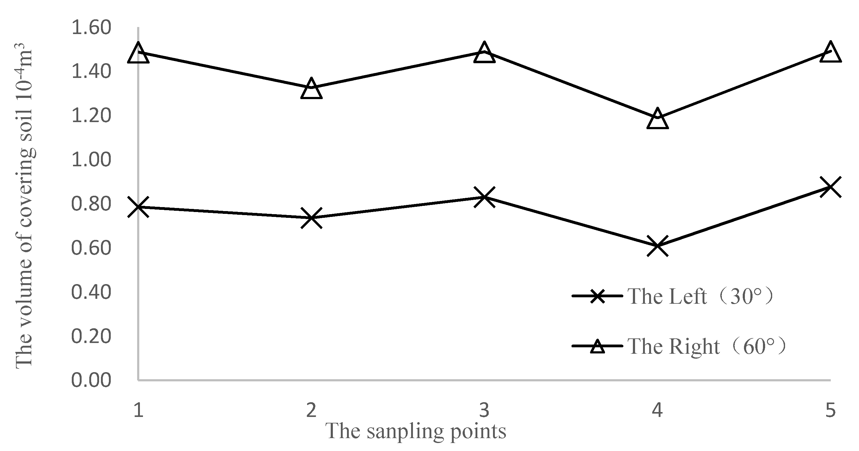
As shown in
Figure 10, when the angles of the soil covering discs on both sides are 30° and 60° the volume of covered soil at the measuring points is 0.61–0.88 × 10
−4 m
3 and 1.19–1.49 × 10
−4 m
3, respectively. The maximum difference of 0.70 × 10
−4 m
3 appears at the first point and the minimum difference of 0.58 × 10
−4 m
3 appears at the fourth point. When the angle of the covering disc is 30°, the volume of covered soil is 0.77 × 10
−4 m
3 and when the angle of the covering disc is 60°, the average volume is 1.40 × 10
−4 m
3.
When the angle of the covering disc is 30°, the amount of soil covering is about 29% compared to that of the first group. The reason may be that the first row is close to the edge of the plot during operation and the soil is not as loose as the middle position and so the covering amount is lesser. When the inclination angle is 60°, the amount of soil covered is close to that of the second group with a difference of less than 2.2%.
Therefore, the reason for the larger change in the volume of covered soil may be caused by soil conditions and the curve can be explained as shown in
Figure 8,
Figure 9 and
Figure 10.
When the angles of covering discs 30°, 45° and 60° are, respectively, fitted and the relationship between the volume of covered soil and the angle of disc is obtained as a quadratic function, as shown in Equation (5). The angle of the disc can be calibrated through the following equation:
where X is the angle of disc, degrees; is the volume of covering soil, 10
−4 m
3.
According to the test data, the uniformity coefficient and stability coefficient of the volume of covered soil under different angles of the soil covering discs are calculated, as shown in
Table 2.
According to the standard, the variation coefficient of uniformity should be less than 40% and the variation coefficient of stability should be less than 7.8%. When the coefficient of variation is less than the specified value, it indicates that the machine possesses good quality covering soil.
As shown in
Table 2, when the angle of the soil covering disc is 30° and 60°, respectively, the uniformity coefficient is relatively small (less than 40%), indicating that the volume of covered soil is more consistent and that the quality is good. When the angle of the soil covering disc is 45°, the uniformity coefficient is relatively large (more than 40%), indicating that the uniformity of the volume of covered soil is not good. When the difference between the angles of the discs on both sides is large (30° and 60°), the standard deviation and variation coefficient of stability coefficient are the lowest (less than 7.8%), indicating that the greater the difference between the discs on the both sides, the easier it is to achieve differential overburden, which is beneficial under sloping fields.
4. Conclusions
This paper designs a soil covering device that can perform linkage and differential adjustments separately and the field experiment was completed to verify the performance of soil covering device. The results show that this device can obtain higher quality potato planting. However, due to the condition of test sloping fields being hard to obtain, in this paper, the flat fields were used to complete the field experiment, which needs verification in further research. Moreover, the Soil-bin Testing Platform for Sloping Field will be installed in the Northwest A&F University, which can be used to test the performance of device in sloping field.
In order to improve the mulching quality, a soil covering device that can realize linkage and differential adjustment was designed and field experiments were carried out to obtain the fitting equation of the volume of covered soil and the angle of the covering disc; the uniformity coefficient and stability coefficient are measured and calculated.
(1) The structure and principle of the soil covering device are put forward and the design calculation and analysis are focused on the four-bar adjustment mechanism and reasonable structural parameters are obtained. The linkage adjustment is carried out through the two-way screw and nut mechanism and the differential adjustment is carried out through the steering mechanism.
(2) By using data fitting, it was found that the volume of covered soil changes in a binomial manner with the angle of the discs. Field test results show the following: when the angles of discs on both sides are the same (30° or 60°), the uniformity coefficient of volume of covering soil is lower than 14% and when the angles of the discs are different (respectively, 30° and 60°), the stability coefficient of volume of covering soil is 4.1% (less than 7.8%), which indicates that the linkage and difference adjustment device can meet the quality requirements of the potato film side covering soil.


