Author Contributions
Conceptualization, R.Y. and D.C.; Data curation, D.C. and X.Z.; Formal analysis, R.Y. and D.C.; Funding acquisition, S.S.; Investigation, R.Y., X.Z. and Z.P.; Methodology, R.Y. and D.C.; Project administration, S.S.; Resources, R.Y. and X.Z.; Software, R.Y. and D.C.; Supervision, S.S.; Validation, R.Y., D.C., X.Z. and Z.P.; Visualization, R.Y. and X.Z.; Writing—original draft, R.Y. and D.C.; Writing—review and editing, R.Y. and D.C. All authors have read and agreed to the published version of the manuscript.
Figure 1.
Installation and working diagram of gap self-adjusting ear-picking plate.
Figure 1.
Installation and working diagram of gap self-adjusting ear-picking plate.
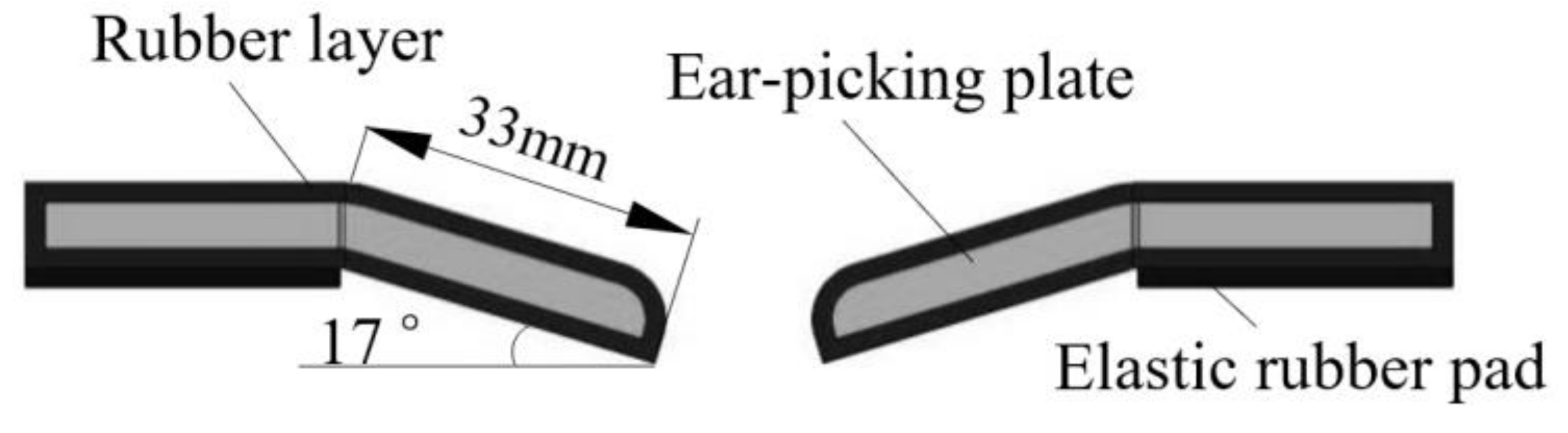
Figure 2.
Structural scheme of V-shaped ear-picking plate.
Figure 2.
Structural scheme of V-shaped ear-picking plate.
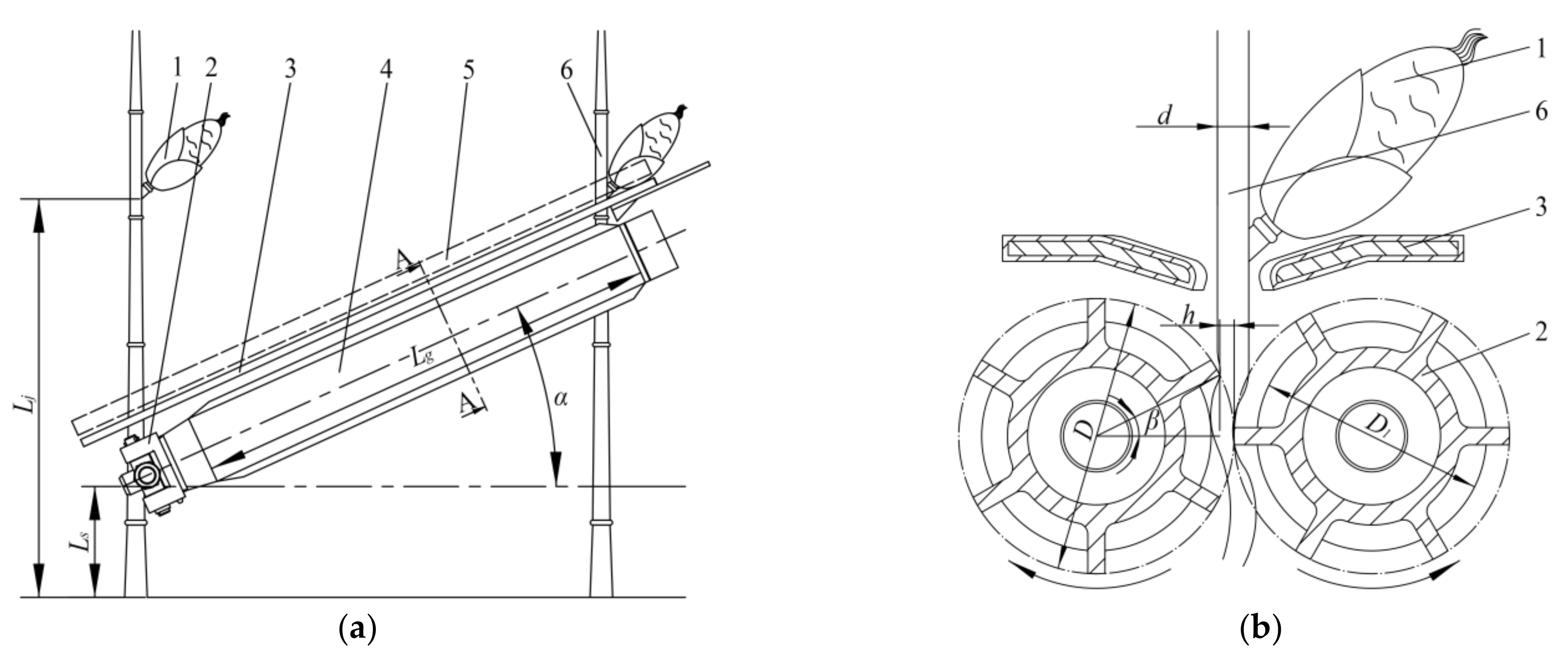
Figure 3.
Working scheme of snapping rolls. 1. Corn ear 2. Snapping rolls 3. Ear-picking plate 4. Snapping rolls gap adjustment device 5. Gathering chain 6. Corn stalk. (a) Working scheme, (b) A-A Cross section scheme. Note: Lj is the ear height of corn plant, mm; Ls is the height of the center line in front of snapping rolls above ground, mm; Lg is the working length of snapping rolls, mm; α is the angle between snapping rolls and horizontal plane, (°); d is the diameter of the stalk at corn ear, mm; h is the working gap of snapping rolls, mm; D is the outer diameter of snapping rolls, mm; D1 is the diameter of snapping rolls drum, mm; β is the grabbing angle of snapping rolls to the stalk, (°).
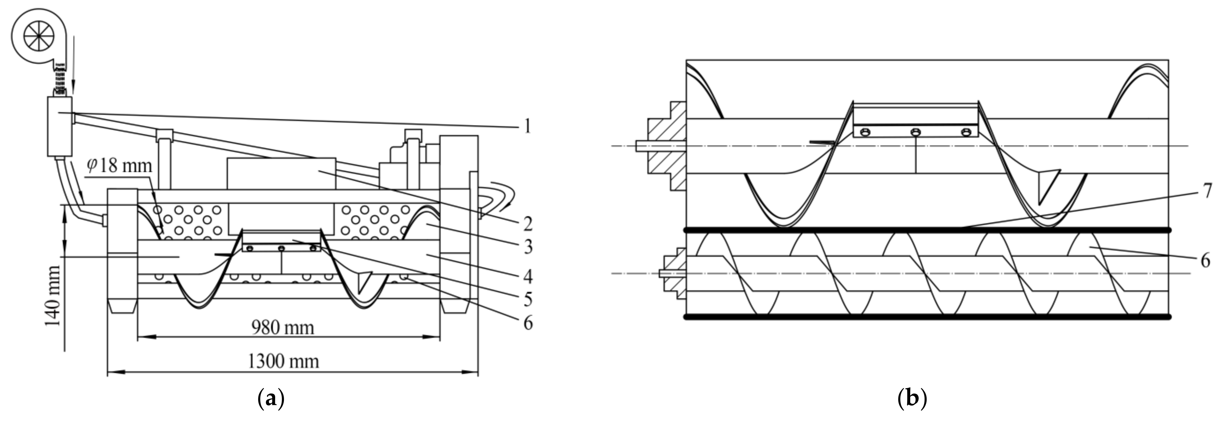
Figure 4.
Cleaning system scheme of ear-picking device. 1. Pneumatic assisted seed cleaning system 2. Auger discharge port 3. Auger blades 4. Ear-conveying auger 5. Scraper 6. Sieve hole cleaning device 7. Auger-type kernel recovery device. (a) Top view, (b) Main view.
Figure 4.
Cleaning system scheme of ear-picking device. 1. Pneumatic assisted seed cleaning system 2. Auger discharge port 3. Auger blades 4. Ear-conveying auger 5. Scraper 6. Sieve hole cleaning device 7. Auger-type kernel recovery device. (a) Top view, (b) Main view.
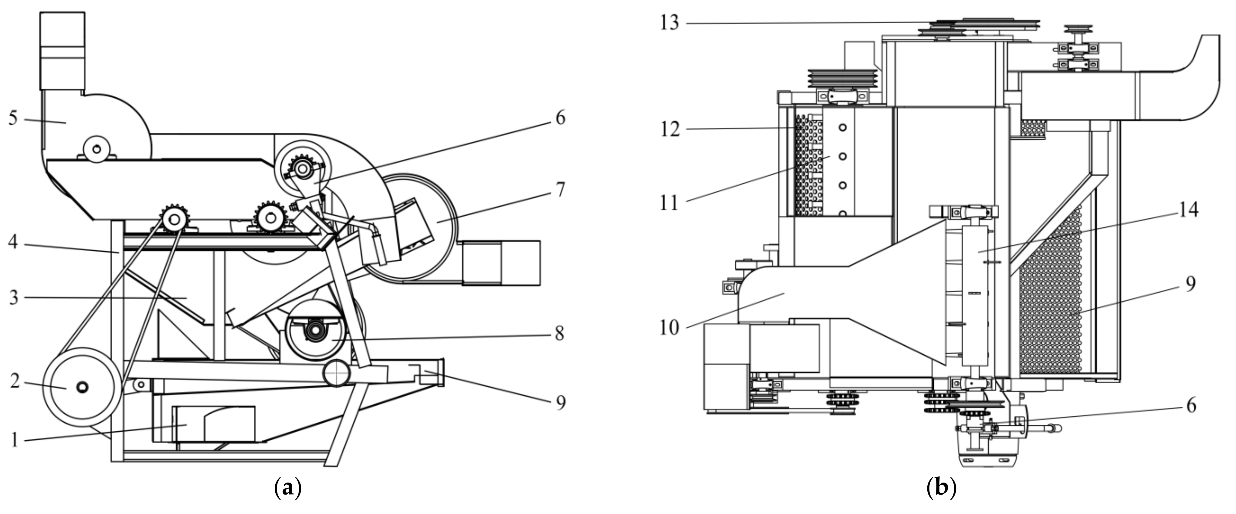
Figure 5.
Structural scheme of threshing device. 1. kernel discharge port 2. Crank drive wheel 3. Inclined guide plate 4. Frame 5. Front fan 6. Clutch adjustment device 7. Rear fan 8. Core discharging device 9. Vibrating sieve 10. Front fan air supply channel 11. Threshing roller 12. Concave plate screen 13. Drive wheel 14. Spiral impurity removal device. (a) Main view, (b) Top view.
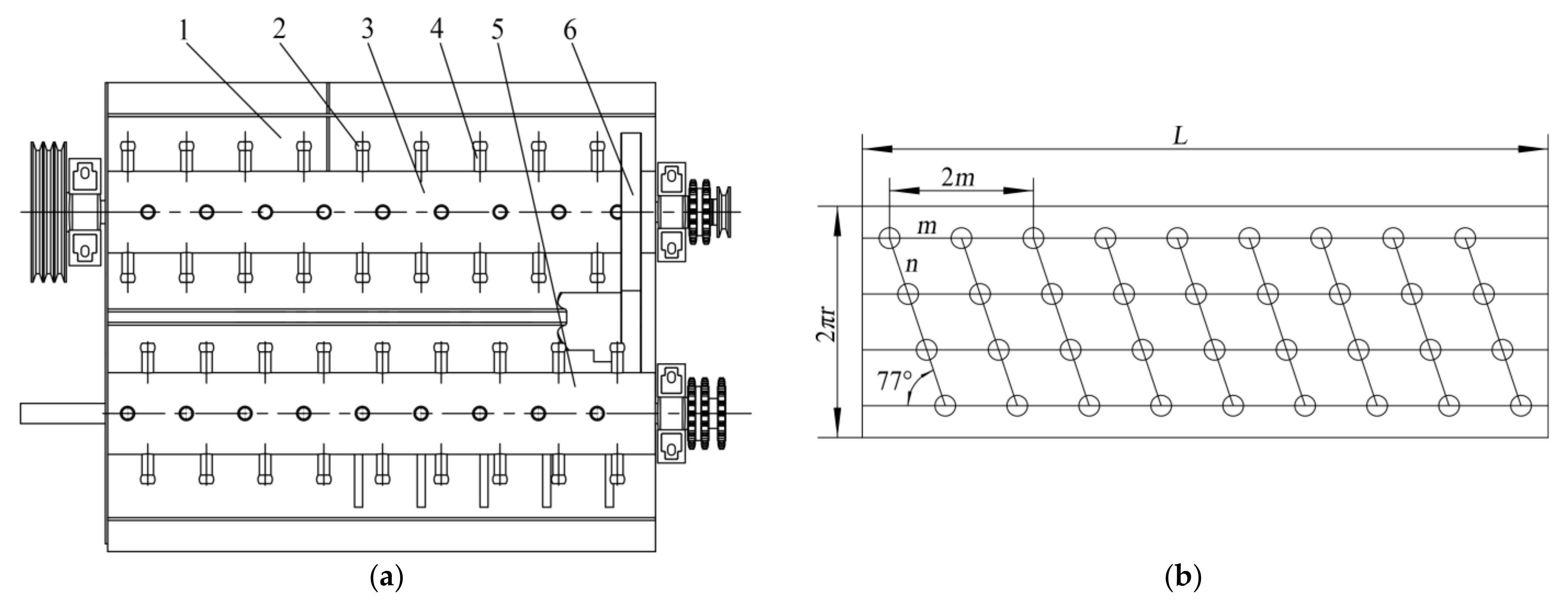
Figure 6.
Model and expansion scheme of threshing drum. 1. Feeding inlet 2. Rubber 3. First drum body 4. Threshing tooth 5. Ear guide plate 6. Second drum body. (a) Structure scheme, (b) Cylinder unfolded view. Note: m is the distance between two adjacent teeth on the same axis, mm; n is the arc length of two adjacent teeth on the same spiral line, mm; L is the drum length, mm.
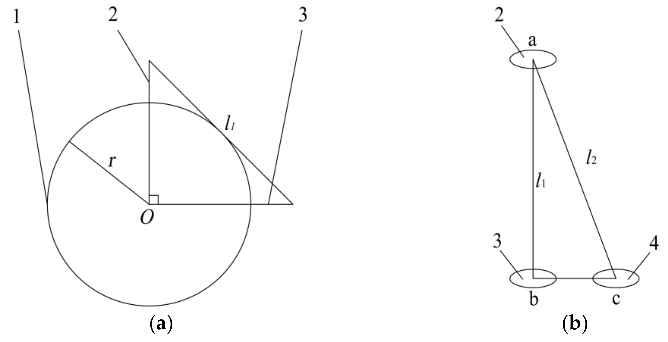
Figure 7.
Mathematical model diagram. 1. Threshing drum 2. Threshing gear a 3. Virtual threshing gear b 4. Threshing gear c. (a) Cylinder section view, (b) Distribution of threshing teeth. Note: l1 is the shortest distance between two teeth tangent to drum body on the same section, mm; l2 is the distance between two teeth tangent to the drum body on the same spiral line, mm; r is the radius of the drum, mm.
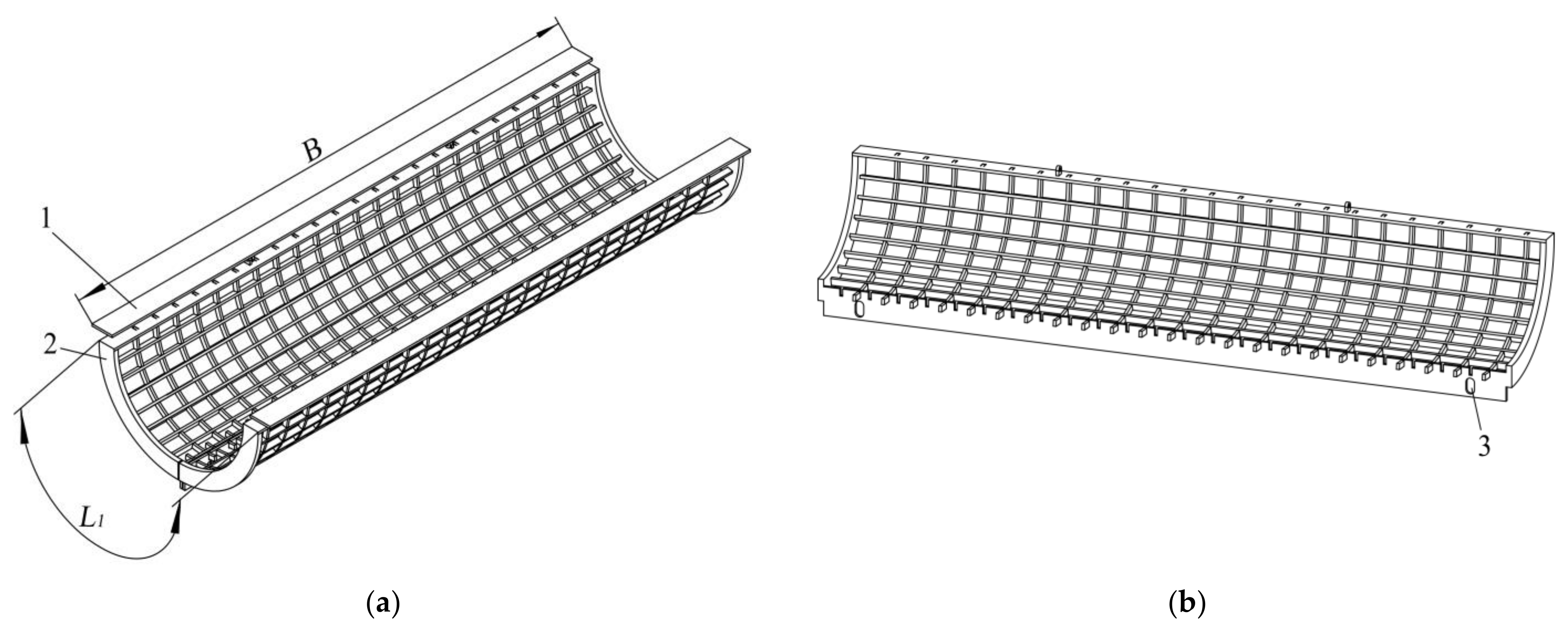
Figure 8.
Concave sieve model diagram. 1. Fixed plate 2. Movable sieve 3. Slot hole. (a) Concave Screen Combination Diagram, (b) Concave sieve split diagram. Note: B is the width of concave, mm; L1 is the arc length of concave, mm.
Figure 8.
Concave sieve model diagram. 1. Fixed plate 2. Movable sieve 3. Slot hole. (a) Concave Screen Combination Diagram, (b) Concave sieve split diagram. Note: B is the width of concave, mm; L1 is the arc length of concave, mm.
Figure 9.
Flowchart of materials and methods.
Figure 9.
Flowchart of materials and methods.
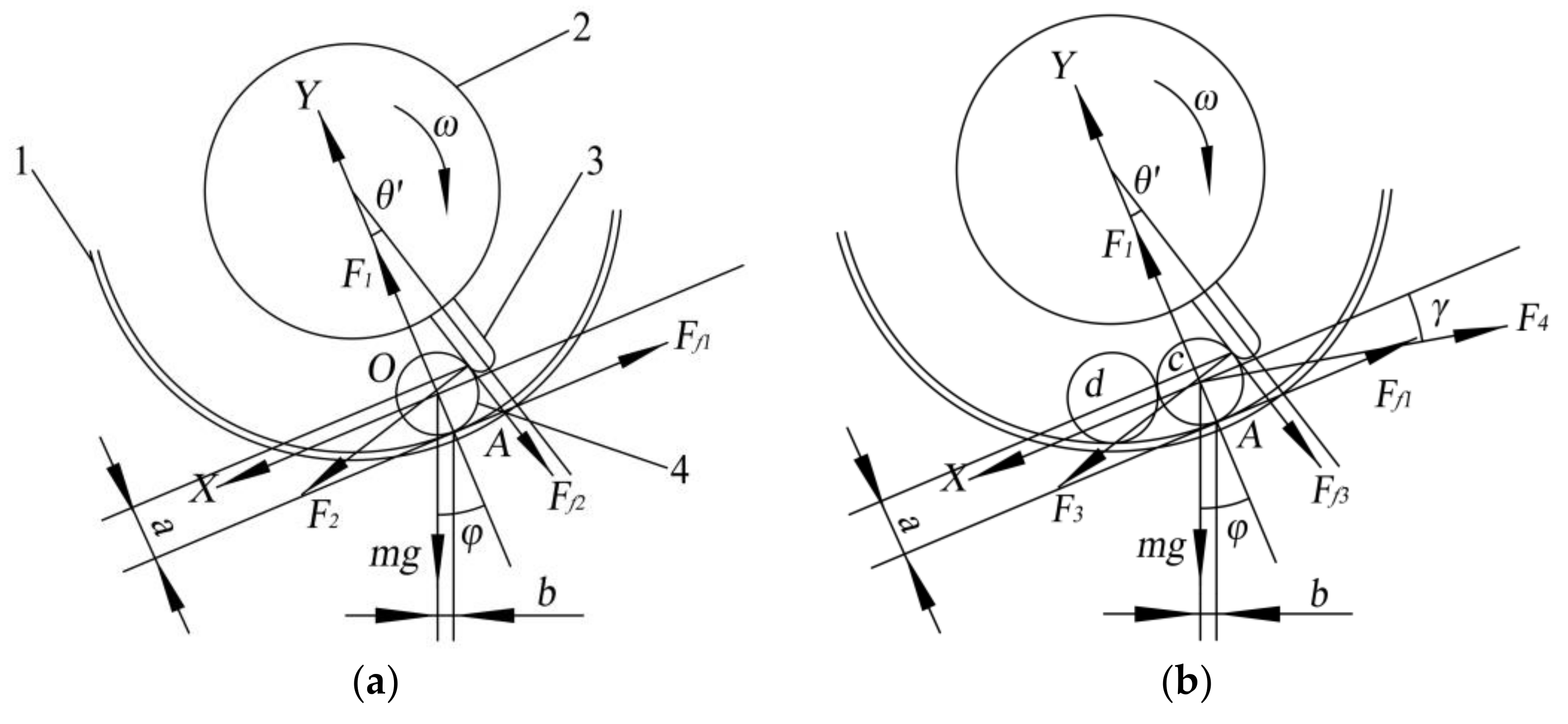
Figure 10.
Stress analysis of corn. 1. Concave sieve 2. Threshing drum 3. Threshing teeth 4. Corn. (a) Low-feeding ear force diagram, (b) High-feeding ear force diagram. Note: F1 is the supporting force of concave sieve on the ear, N; F2 is the impact of threshing teeth on the ear, N; F3 is the impact force of threshing tooth on ear c, N; F4 is the pressure of ear d on ear c, N; μ1 is the friction coefficient between the ear and concave sieve; μ2 is the friction coefficient between the ear and threshing teeth; Ff1 is the friction between the ear and concave sieve, N; Ff2 is the friction between the ear and threshing teeth, N; Ff3 is the friction force between ear c and threshing tooth, N; θ’ is the included angle between Y axis and the axis of the threshing tooth, °; φ is the angle between Y axis and the direction of gravity, °; γ is the angle between the pressure F4 and the friction force Ff1, °; ω is the angular speed of the drum, rad/s; r is ear radius, mm; a is the distance from the intersection of ear and the threshing tooth to the concave sieve, mm; b is the distance from the barycenter of the ear to the concave sieve, mm.
![Agriculture 11 00904 g010]()
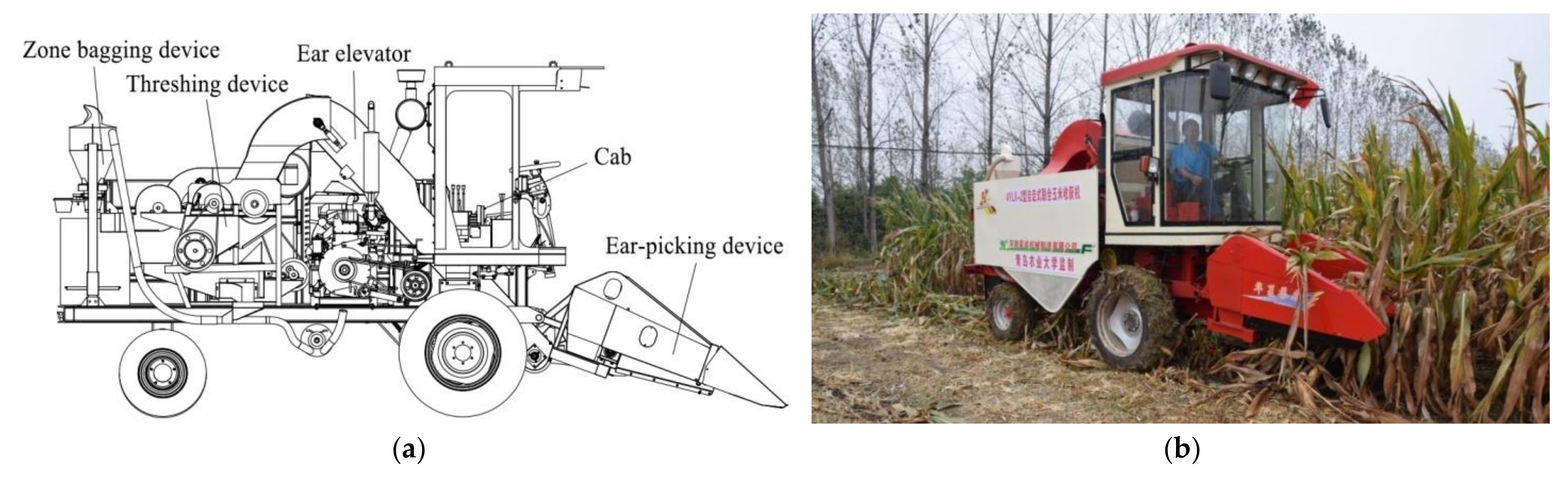
Figure 11.
Ear-picking device and threshing device with 4YZL-2 corn plot kernel harvester. (a) Structural diagram, (b) Real machine diagram.
Figure 11.
Ear-picking device and threshing device with 4YZL-2 corn plot kernel harvester. (a) Structural diagram, (b) Real machine diagram.
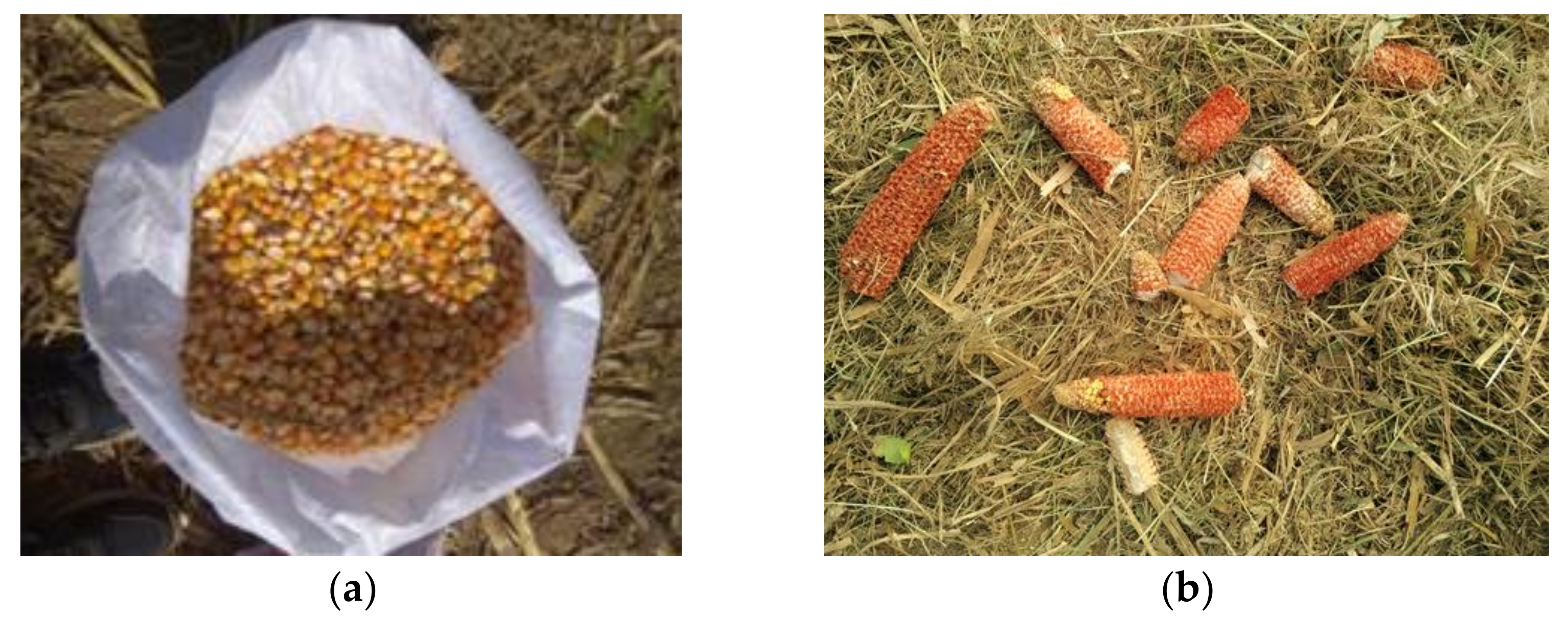
Figure 12.
Presentation of harvest result. (a) Harvested corn grain, (b) threshed corn.
Figure 12.
Presentation of harvest result. (a) Harvested corn grain, (b) threshed corn.
Figure 13.
Distribution of test measured and fitted values. (a) Fitting curve of breakage rate, (b) fitting curve of non-threshing rate.
Figure 13.
Distribution of test measured and fitted values. (a) Fitting curve of breakage rate, (b) fitting curve of non-threshing rate.
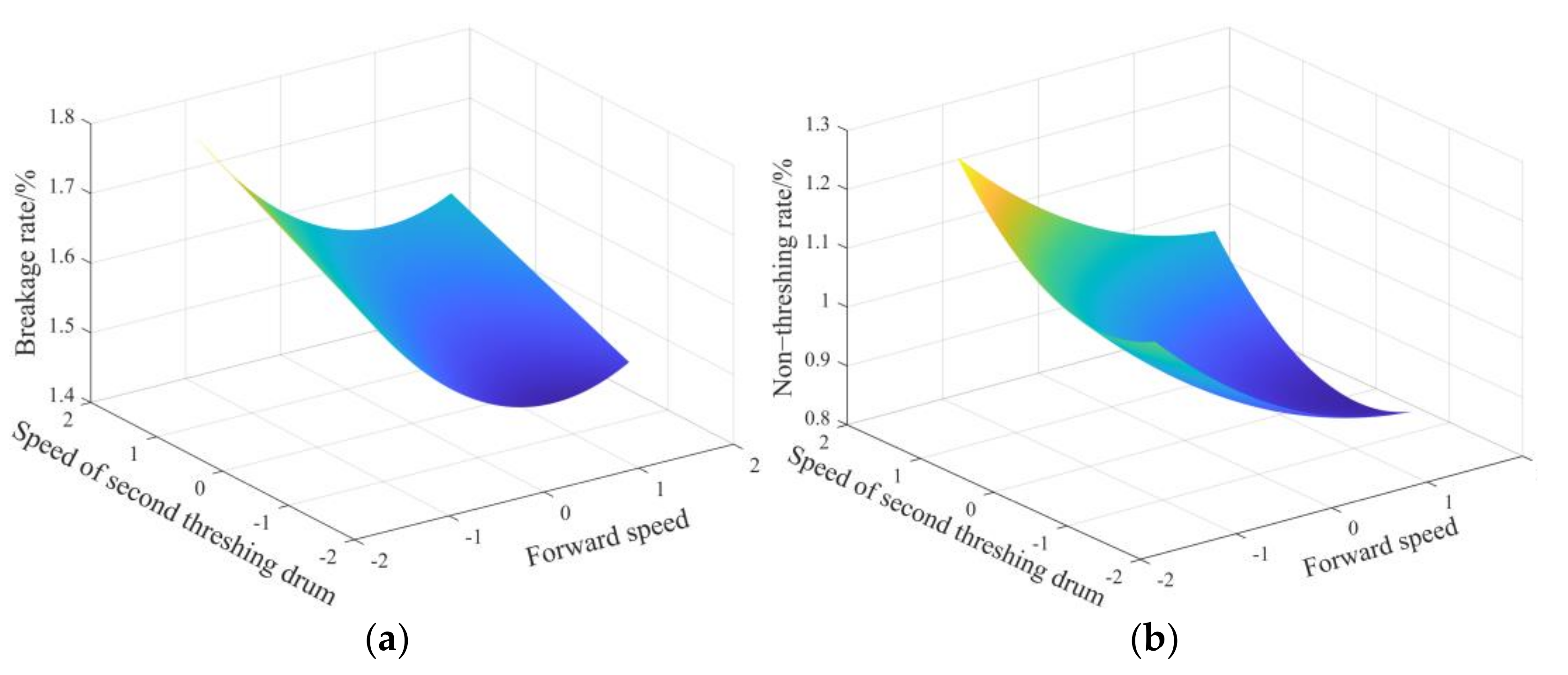
Figure 14.
Interaction between the forward speed and the speed of the second threshing drum. (a) Effect on breakage rate, (b) effect on the non-threshing rate.
Figure 14.
Interaction between the forward speed and the speed of the second threshing drum. (a) Effect on breakage rate, (b) effect on the non-threshing rate.
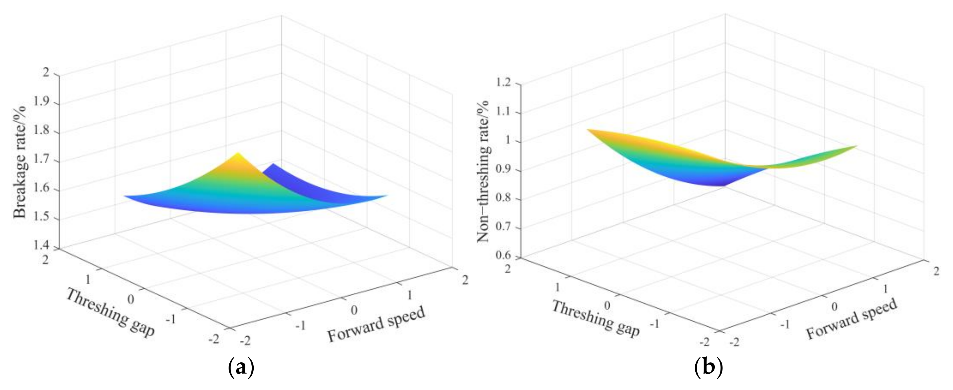
Figure 15.
Interaction between the forward speed and the threshing gap. (a) Effect on breakage rate, (b) effect on the non-threshing rate.
Figure 15.
Interaction between the forward speed and the threshing gap. (a) Effect on breakage rate, (b) effect on the non-threshing rate.
Figure 16.
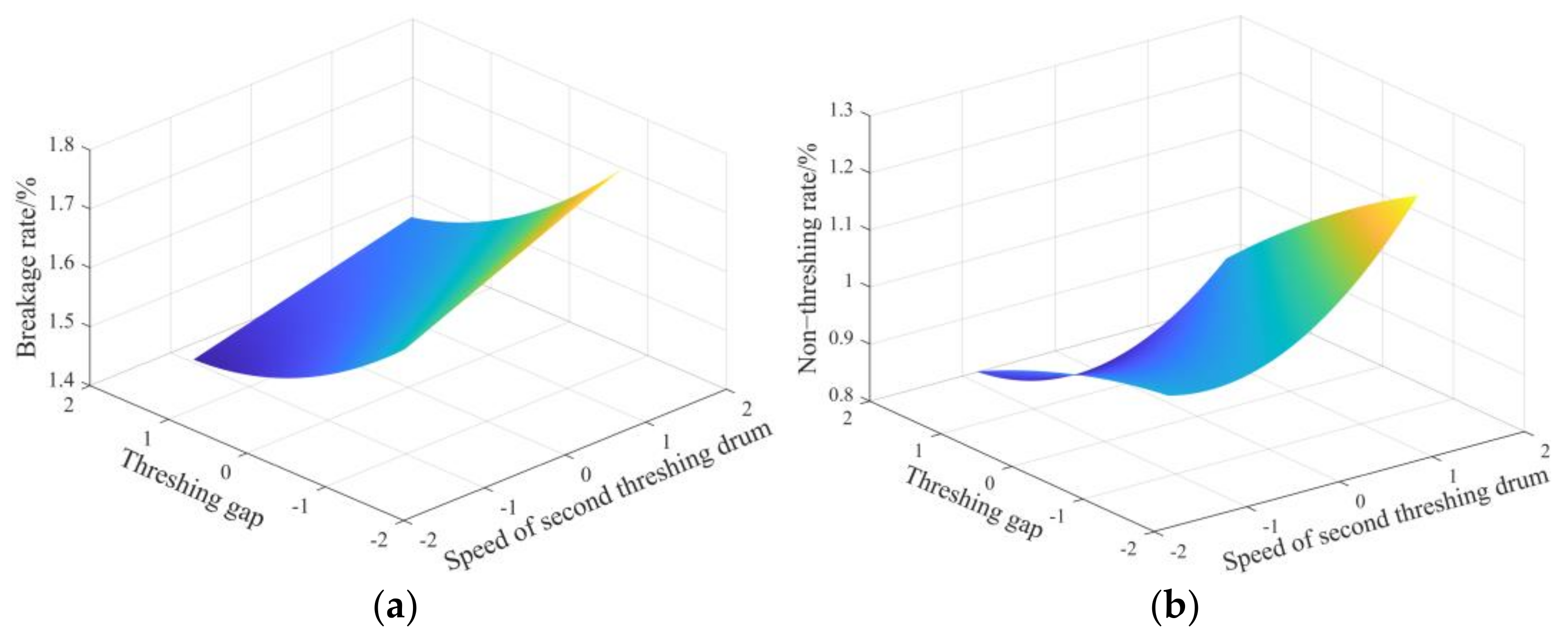
Interaction between the speed of the second threshing drum and the threshing gap. (a) Effect on breakage rate, (b) effect on the non-threshing rate.
Figure 16.
Interaction between the speed of the second threshing drum and the threshing gap. (a) Effect on breakage rate, (b) effect on the non-threshing rate.
Table 1.
Corn basic characteristic parameters in the plot.
Table 1.
Corn basic characteristic parameters in the plot.
| Parameters | Value |
|---|
| Average ear length/mm | 174.36 |
| Average weight per ear/kg | 0.348 |
| Average diameter of large end/mm | 54.2 |
| Average diameter of small end/mm | 35.8 |
| Kernel moisture content/% | 21~26 |
Table 2.
Main technical parameters of plot corn kernel harvester.
Table 2.
Main technical parameters of plot corn kernel harvester.
| Parameters | Value |
|---|
| Structure form | Self-propelled wheel |
| Type of diesel engine | JDM490 |
| Rated power of engine/kW | 37 |
| Rated speed of engine/(r·min−1) | 2400 |
| Vehicle weight/kg | 2600 |
| Harvest rows/row | 2 |
| Minimum ground clearance/mm | 250 |
| Applicable line spacing/mm | 550~650 |
| Size/(mm × mm × mm) | 5200 × 1300 × 2650 |
| Working width/mm | 1200 |
Table 3.
Experimental factors and levels.
Table 3.
Experimental factors and levels.
| | Factors | Forward Speed z1/(m· s−1) | Speed of Second Threshing Drum z2/ (r·min−1) | Threshing Gap z3/mm |
|---|
| Levels | |
|---|
| 1 | 0.5 | 500 | 20 |
| 2 | 0.88 | 650 | 30 |
| 3 | 1.26 | 800 | 40 |
Table 4.
Coding method of experimental factors.
Table 4.
Coding method of experimental factors.
| | Code | Forward Speed Z1/(m· s−1) | Speed of Second Threshing Drum Z2/ (r·min−1) | Threshing Gap Z3/mm |
|---|
| Factors | |
|---|
| r (Z2j) | 1.26 | 800 | 40 |
| 1(Z0j + Δj) | 1.16 | 760.86 | 37.39 |
| 0(Z0j) | 0.88 | 650 | 30 |
| 1(Z0j − Δj) | 0.6 | 539.14 | 22.61 |
| −r (Z1j) | 0.50 | 500 | 20 |
| Δj = (Z2j − Z1j)/2r | 0.28 | 110.86 | 7.39 |
| xj = (Zj − Z0j)/Δj | x1 = 3.571(z1 − 0.52) | x2 = 0.009(z2 − 650) | x3 = 0.135(z3 − 30) |
Table 5.
Test program and results by quadratic regression orthogonal combination design.
Table 5.
Test program and results by quadratic regression orthogonal combination design.
| Factors | x0 | x1 | x2 | x3 | x1x2 | x1x3 | x2x3 | x12 | x22 | x32 | y1 | y2 |
|---|
| Test | |
|---|
| 1 | 1 | 1 | 1 | 1 | 1 | 1 | 1 | 1 | 1 | 1 | 1.54 | 0.83 |
| 2 | 1 | 1 | 1 | −1 | 1 | −1 | −1 | 1 | 1 | 1 | 1.66 | 1.12 |
| 3 | 1 | 1 | −1 | 1 | −1 | 1 | −1 | 1 | 1 | 1 | 1.48 | 0.78 |
| 4 | 1 | 1 | −1 | −1 | −1 | −1 | 1 | 1 | 1 | 1 | 1.55 | 0.95 |
| 5 | 1 | −1 | 1 | 1 | −1 | −1 | 1 | 1 | 1 | 1 | 1.62 | 1.07 |
| 6 | 1 | −1 | 1 | −1 | −1 | 1 | −1 | 1 | 1 | 1 | 1.87 | 1.19 |
| 7 | 1 | −1 | −1 | 1 | 1 | −1 | −1 | 1 | 1 | 1 | 1.53 | 0.98 |
| 8 | 1 | −1 | −1 | −1 | 1 | 1 | 1 | 1 | 1 | 1 | 1.76 | 1.05 |
| 9 | 1 | −r | 0 | 0 | 0 | 0 | 0 | r2 | 0 | 0 | 1.69 | 1.13 |
| 10 | 1 | r | 0 | 0 | 0 | 0 | 0 | r2 | 0 | 0 | 1.59 | 0.81 |
| 11 | 1 | 0 | −r | 0 | 0 | 0 | 0 | 0 | r2 | 0 | 1.49 | 0.92 |
| 12 | 1 | 0 | r | 0 | 0 | 0 | 0 | 0 | r2 | 0 | 1.61 | 1.09 |
| 13 | 1 | 0 | 0 | −r | 0 | 0 | 0 | 0 | 0 | r2 | 1.67 | 0.96 |
| 14 | 1 | 0 | 0 | r | 0 | 0 | 0 | 0 | 0 | r2 | 1.51 | 0.84 |
| 15 | 1 | 0 | 0 | 0 | 0 | 0 | 0 | 0 | 0 | 0 | 1.56 | 0.93 |
| 16 | 1 | 0 | 0 | 0 | 0 | 0 | 0 | 0 | 0 | 0 | 1.57 | 0.91 |
| 17 | 1 | 0 | 0 | 0 | 0 | 0 | 0 | 0 | 0 | 0 | 1.54 | 0.95 |
Table 6.
Variance analysis for breakage rate.
Table 6.
Variance analysis for breakage rate.
| Source | Sum of Squares | Degree of Freedom | Mean Square | F Value | p-Value |
|---|
| x1 | 0.040 | 1 | 0.0402 | 58.98 | 0.00012 ** |
| x2 | 0.024 | 1 | 0.0243 | 35.59 | 0.00056 ** |
| x3 | 0.067 | 1 | 0.0674 | 98.70 | 0.00002 ** |
| x1x2 | 0.0001 | 1 | 0.00011 | 0.165 | 0.69693 |
| x1x3 | 0.011 | 1 | 0.0105 | 15.40 | 0.00572 ** |
| x2x3 | 0.0006 | 1 | 0.00061 | 0.897 | 0.37511 |
| x12 | 0.016 | 1 | 0.0161 | 23.65 | 0.00183 ** |
| x22 | 0.00000004 | 1 | 0.00000004 | 0.00006 | 0.99391 |
| X32 | 0.0032 | 1 | 0.0032 | 4.653 | 0.06791 |
| Regression | 0.163 | 9 | 0.0181 | 26.45 | 0.00014 ** |
| Residuals | 0.0048 | 7 | 0.00068 | / | / |
| Lack of fit | 0.0043 | 5 | 0.00086 | 1.58 | 0.2691 |
| Error | 0.00047 | 2 | 0.00023 | / | / |
| Total | 0.1673 | 16 | / | / | / |
Table 7.
Variance analysis for non-threshing rate.
Table 7.
Variance analysis for non-threshing rate.
| Source | Sum of Squares | Degree of Freedom | Mean Square | F Value | p-Value |
|---|
| x1 | 0.09328 | 1 | 0.0933 | 65.77 | 0.000084 ** |
| x2 | 0.03965 | 1 | 0.0397 | 27.96 | 0.001138 ** |
| x3 | 0.05659 | 1 | 0.0566 | 39.901 | 0.000398 ** |
| x1x2 | 0.000013 | 1 | 0.000013 | 0.0088 | 0.9278 |
| x1x3 | 0.00911 | 1 | 0.0091 | 6.425 | 0.03896 * |
| x2x3 | 0.00361 | 1 | 0.0036 | 2.547 | 0.1545 |
| x12 | 0.00575 | 1 | 0.0058 | 4.051 | 0.08401 |
| x22 | 0.0157 | 1 | 0.0157 | 11.07 | 0.01264 * |
| X32 | 0.00054 | 1 | 0.00054 | 0.3793 | 0.5575 |
| Regression | 0.22425 | 9 | 0.0249 | 17.568 | 0.00052 ** |
| Residuals | 0.00993 | 7 | 0.00141 | / | / |
| Lack of fit | 0.00913 | 5 | 0.00183 | 4.564 | 0.1894 |
| Error | 0.0008 | 2 | 0.0004 | / | / |
| Total | 0.2342 | 16 | / | / | / |
Table 8.
Significance analysis of regression coefficient on the test results.
Table 8.
Significance analysis of regression coefficient on the test results.
| Inspection Items | y1 | y2 |
|---|
| R | 0.9856 | 0.9786 |
| R2 | 0.9714 | 0.9576 |
| Adj R2 | 0.9668 | 0.9503 |
| S | 0.0261 | 0.0377 |
Durbin-Watson
statistic | 2.7176
(1 < d < 3) | 2.1973
(1 < d < 3) |
Table 9.
Optimum parameters test results.
Table 9.
Optimum parameters test results.
| | Breaking Rate y1/% | Non-Threshing Rate y2/% | Fmin/% |
|---|
| Theoretical value | 1.45 | 0.82 | 2.27 |
| Field test validation value | 1.47 | 0.89 | 2.36 |


