1. Introduction
The impact of chemical pesticides became an important global issue for the sustainability of the food production system. More and more organic food is produced and has become popular all over the world. One reason for the use of chemical pesticides is to reduce weeds, as they can be responsible for high yield losses [
1]. However, to leave them untreated is not an option, as weeds could be responsible for a decrease of up to 40% of yield [
2,
3]. The importance of mulching and weeding in vineyards was already conducted in different studies. It was proclaimed that organic mulching was the most sustainable practice for yearly vine production [
4]. In order to reduce chemical weed control, mechanical weeding approaches are promising alternatives. Mechanical weed control can be conducted between the tree/crop rows (inter-row) and within the tree/crop rows (intra-row). The main challenge of mechanical weed control is the realization at the intra-row area [
5]. Weeding close to the crop/trunk and the use of intra-row weeding tools needs a very accurate steering for not damaging the crop/trunk [
6]. Therefore, accurate guidance systems are needed. During the last decades, navigation has been improved by the use of new automatic row guidance systems using feelers, Global Navigation Satellite Systems (GNSS), distance sensors and cameras [
7,
8,
9]. The development of these technologies has created wide opportunities for weed management and may become a key element of modern weed control [
10]. Anyhow, in order to increase the selectivity of the weed control and reduce the crop plants damage, intelligent autonomous weeding systems are needed. Identifying individual weeds and crops is possible by the use of mechanical feelers, GNSS coordinates, sonar sensors, laser scanners, or cameras [
11,
12,
13,
14]. Automation offers the possibility to determine and differentiate crops from weeds and at the same time, to remove the weeds with a precisely controlled device. Automated weeding implements developed [
15,
16,
17,
18], provide examples of how the control of mechanical weeding can be performed. Real-time weeding robots have the potential to control intra-row weeds plus reduce the reliance on herbicides and hand weeding [
19,
20].
For reducing labor costs of mechanical weed control the whole task has to be automated. This approach could result in self-guided, self-propelled and autonomous machines that could cultivate crops with minimal operator intervention. Weeding robots can improve labor productivity, solve labor shortage, improve the environment of agricultural production, improve work quality, reduce energy input, improve resource management, and help farmers to change their traditional working methods and conditions [
21]. Introducing self-governing mobile robots in agriculture, forestry and landscape conservation is dependent on the natural environment and the structure of the facilities. The solution proposed is the use of little and light machines, like unmanned vehicles that are self-propelled, autonomous and low powered [
22]. Mobile robots must always be aware of its surroundings such as unpredicted obstacles [
23]. To this scope, real-time environment detection could be performed using different sensor systems.
There were several autonomous machines and robots developed in the past [
24]. Zhang et al. investigated the performance of a mechanical weeding robot [
25]. They used machine vision to locate crop plants and a side shift mechanism to move along the crop rows. The intra-row weeds were controlled by moving hoes that could open and close to prevent damage to crop plants. Another study by Nørremark et al. developed an automatic GNSS-based intra-row weeding machine using a cycloid hoe [
13]. The weeder used eight rotating tines, which could be released to tolerate crop plants. This automated weeding system mainly used Real Time Kinematic (RTK)-GNSS to navigate and control the side-shifting frame plus a second RTK-GNSS to control the rotating tines. Astrand and Baerveldt investigated the performance of a vision-based intra-row robotic weed control system [
16]. The robotic system implemented two vision systems to guide the robot along the crop row and to discriminate between crops and weed plants. The weeding tool consisted of a rotating wheel connected to a pneumatic actuator that lifted and lowered the weeding tool to tolerate crop plants. Robots for weeding in vineyards were also developed, mainly focusing on trunk detection [
26,
27]. Weeds in vineyards can cause significant reductions in vine growth and grape yields [
11]. Conventional control methods rely on herbicide applications in the vine rows and the area between them (middles), or a combination of herbicide strip application in the vine row and mowing or disking of the middles [
28]. For a mobile robot to navigate in between the vine or tree rows, it must detect the position of the rows first, by means of detecting the trunks. The complete integration of an under-vine rotary weeder in an autonomous robot system for active intra-row weeding in vineyards and orchards was not done until now.
The overall goal of the current research was to develop and test the performance of a rotating electrical tiller weeder mechanism, built for automated intra-row weeding for vineyards. The system should be integrated in an autonomous robot platform and should be evaluated under controlled soil bin and outdoor conditions. The power requirement of the rotary blades mechanism and the total power for the autonomous robotic machine were of interest. The second interest was to test and compare two control strategies for detecting trunks, using a sonar sensor and a feeler.
2. Materials and Methods
2.1. Mechanics and Electronics
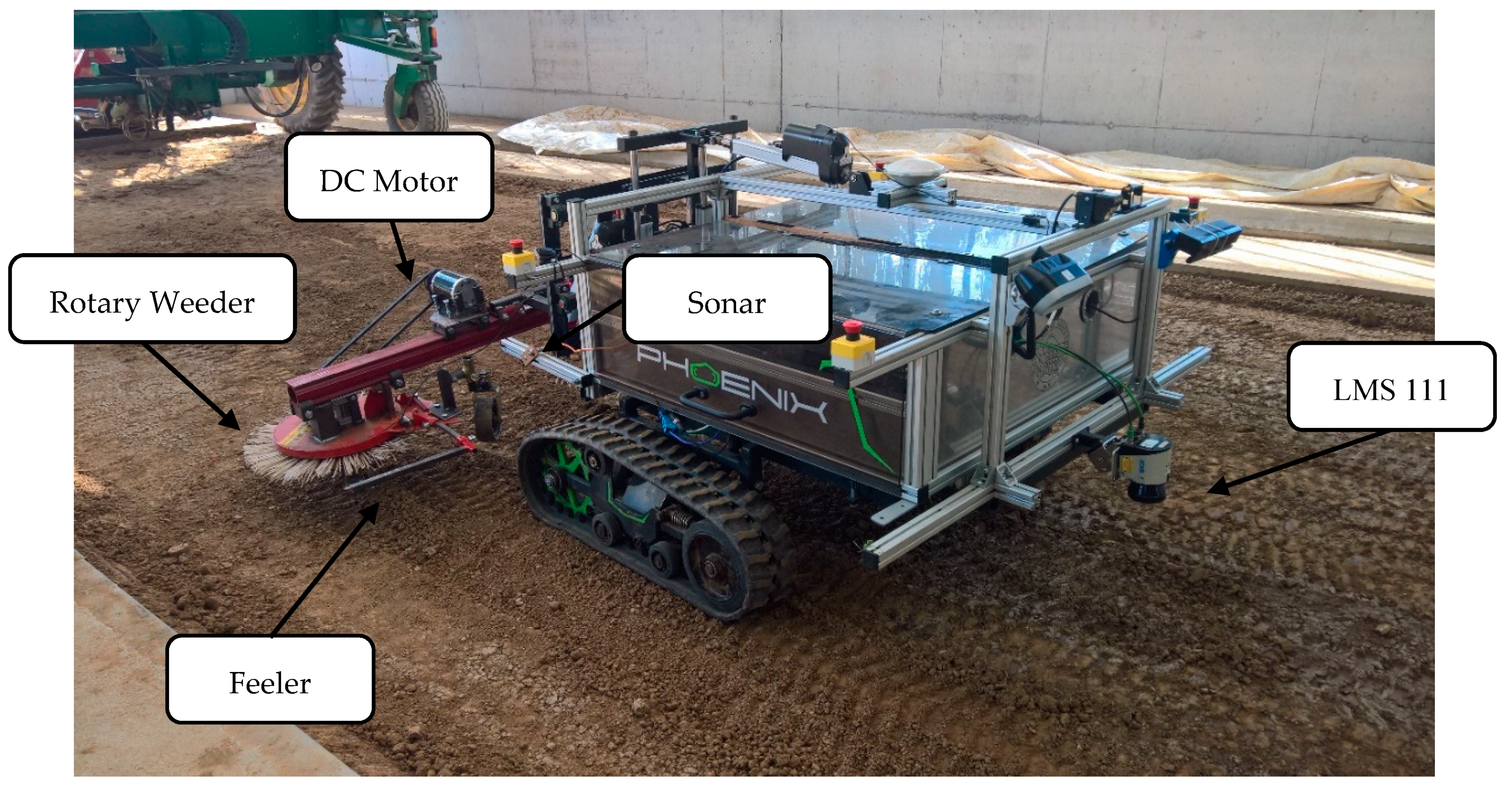
An electric tiller head rotary weeder cultivator was manufactured and designed in the laboratory of the Institute of Agricultural Engineering, Hohenheim University and was mounted to an autonomous caterpillar robot called “phoenix” [
14] (see
Figure 1). The prototype electric rotary weeder was built up using a rotary weeder from Humus Co. called “Humus Planet” (Humus, Bermatingen, Germany). This tool originally operated with a hydraulic motor and was redesigned to get driven by an electric DC motor. A 1 kW 48DC brushed motor model ZY1020 (Ningbo Jirun Electric Machine Co.,Ltd., Nigbo, China) was used. The motor had a nominal torque of 2 Nm and a rated speed of 3200 rpm. The motor was mounted using a gearbox reducing with 30:1 ratio to produce a nominal torque of 60 Nm and a motor speed of 106 rpm at the rotary weeder. The gearbox was directly connected with a drive shaft to the rotary weeder. The motor and the gearbox were connected using a v-belt. The developed rotary weeder was fixed on a metal bar together with the drive unit.
The whole implement was attached to the robot using a coupling triangle. The implement could be moved up, down, left, right and could be tilted with the help of three Linak LA36 actuators (Linak, Nordborg, Denmark). They were capable of creating a pull/push force between 1700 N and 4500 N. This was sufficient to move the implement under all circumstances. The robot system was driven by two brushless motors HBL5000 (Golden Motor Technology Co., Ltd., Jiangsu, China), creating a maximum driving power of 10 kW, sufficient to move the 500 kg weight of the robot plus implement even in harsh terrain. The two times 80 × 15 cm belt system of the phoenix minimized soil compaction and provided enough grip and pull force for mechanical weeding. The width of the robot was 1.70 m. The implement could move 30 cm side wards, to move the tool inside the crop row. The power of the whole robot system was provided by batteries, with a nominal voltage of 48 V and 304 Ah. The implement motor was powered by a motor controller Model LB57 (Yongkang YIYUN Elektronic Co., Ltd., Zhejiang, China). The drive motors were controlled by two ACS48S motor controllers (Inmotion Technologies AB, Stockholm, Sweden). The whole robot was controlled and programmed with an embedded computer with i5 processor, 4 GB Ram and 320 GB disk space.
2.2. Sensors
For following the tree and vine rows, a LMS 111 (Sick, Waldkirch, Germany) 2D laser scanner was used [
29]. The mounting of the scanner was in the front of the vehicle to enable a security stop if an obstacle appeared in front of the robot. Additionally, there were four security switches attached to the robot, disabling the drive and implement motors in case of an emergency. For gaining the heading and traveled distance, an Inertial Measure Unit VN100 (VectorNav, Dallas, TX, USA) was fused with the hall sensor information of the drive motors [
30]. The traveling distance was defined by the hall sensors, and the heading was estimated with the IMU. For guiding the implement, two different methods and sensors were tested. The first method used a standard feeler, a modified version of the original feeler of the rotary weeder. As the second method, a sonar sensor pico + 100/U (microsonic, Dortmund, Germany) was used to detect the trunks [
31]. This sensor was used to detect the trunks, because it could be placed at any position at the robot. The signal could directly replace the input signal of the feeler without any additional software changes.
The specifications of the different sensor systems can be found in
Table 1. The data of the feeler and the sonar sensor were digitalized using an analog digital converter from RedLab 1208LS (Meilhaus Electronic, Alling, Germany). This information could be used to send control signals to the implement and the linear motors.
2.3. Software
The control and data logging of the whole robot system and implement was programmed using ROS Indigo-middleware [
32]. The embedded computer ran under Ubuntu 14.04. All parts of the guidance software were programmed using C/C++. All data created were pushed to a so called “topic” which could be time stamped and recorded with the ROS system. This data could be analyzed for evaluating the power consumption, the movement of the robot and the implement behavior. The movement and the transformations between the robot base and the implement was performed using the Transform Library of ROS [
33].
The guidance of the robot was performed with the use of 2D laser scanner data. First the data were converted to Cartesian coordinates and were filtered with a range filter of 5 m. The points were separated into two clusters, one for the left and one for the right side of the row. This was done by separating all points exactly at the laser scanner position into two point clouds (left and right). Afterwards the points were filtered using a Euclidean Clustering method using a distance threshold of 1.5 m. The resulting cluster with the highest point cloud number was estimated as the row point cluster. This clustering helped to get the row filtering more robust. The resulting points of each side were afterwards used to estimate a best fit line with the use of a RANSAC algorithm [
34]. This resulted in two estimated lines, one for each row side. The median of the two resulting lines was used to define the row direction and the next goal point. When one line was missing, or a fixed distance to the row was needed, like in this weeding application, a fixed offset to one side could be set.
In this application a side offset of 0.15 m to the right side detected row was used. Therefore, the implement could move 0.15 m inside the crop row, as the maximum side shift was limited to 0.3 m. The forward speed was controlled by the software and just an active angle adjustment was done based on the line following algorithm of the laser scanner. The robot drive motor controller and the implement motors were controlled with CAN bus signals. The update rate of the motor control was fixed to 10 Hz.
The control of the implement was realized in a separate ROS node, analyzing the values of the switch and the sonar sensor. As soon as the feeler or the sonar detected an obstacle like a trunk, the linear actuator was shifted “inside”. When there was no obstacle detected, the actor moved “outside” until the maximum outer position was reached. The robot program could be started and stopped using a basic joystick. There were two different programs available, one using just the sonar value and one the feeler signals. The feeler signal just included a digital signal. The output of the sonar sensor was an analog signal between 0 and 10 V. This sensor output correlated with the object distance, detected by the sensor. As soon as the limit distance of 5V was read in the ADC Redlab, a digital input signal was triggered, shifting the actuator “inside”.
The height of the implement could be fixed to one depth, or could use the actual motor current of the implement to control the depth dependent on the motor torque. This could help to minimize the necessary force and prevent the rotary tiller weeder to get stuck. In the indoor soil bin, the height was fixed, as the surface was even and without any huge disturbances. In the outdoor tests the adaptive height adjustment variance was used to adjust the implement to the soil surface.
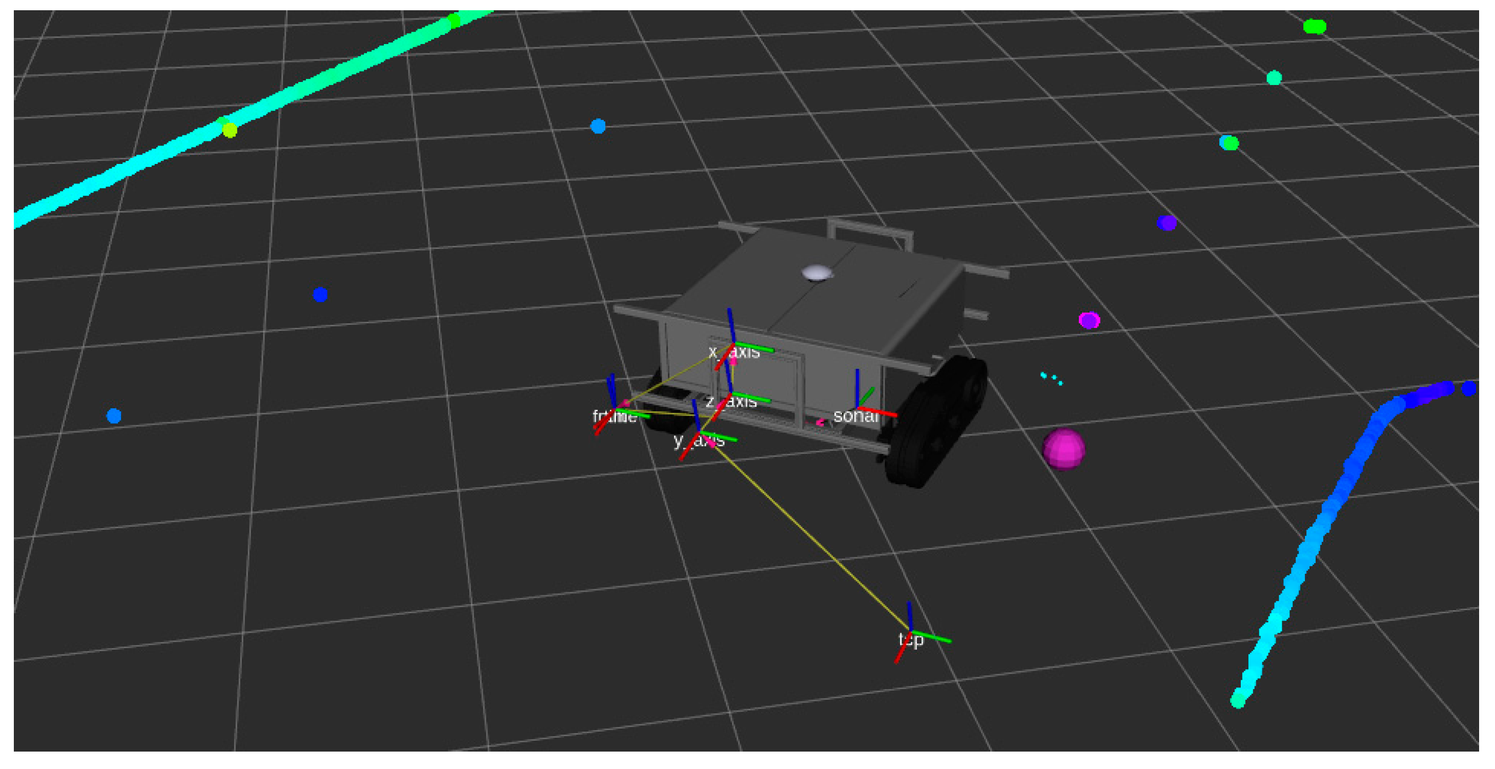
The following
Figure 2 shows the ROS-visualization tool “rviz” used to visualize the live data, acquired at the robot system. The robot pose was visualized in real time together with the implement pose, the laser scanner data, the sonar data and the next waypoint the robot wanted to follow. This helped to debug the system while programming and provided feedback to the user.
The tilled area in the vineyard was analyzed by using the open source software ImageJ version 5.22 [
35]. For further processing of the gained data, the software Microsoft Excel (Microsoft Corporation, Redmond, WA, USA) was used.
2.4. Test Environments
The indoor experiment was performed at the Hohenheim University soil bin laboratory. The indoor soil bin had 46 m length, 5 m width and 1.2 m depth. The mixture of the soil content was 73% sand, 16% silt and 11% clay. The soil was prepared by a rotary harrow, first loosening the soil and afterwards re-compacting the upper soil layer using a flat roller. 22 different plots were prepared and the soil was marked and oriented by using poles of wood with the size of 3 × 3 × 160 cm. The poles were separated with 1.5 m distance and simulated the trees/trunks for the indoor test. The total area evaluated for the treatment quality between every two poles was 0.45 m2 (1.5 m length, 0.3 m row width). This area was divided into 18 rectangles marked on the soil by using chalk. After the experiment, the rectangles with no interaction with the tiller were defined as non-tilled area. Three main soil parameters were recorded for each individual plot. The penetration resistance, soil moisture content and soil shear strength conditions were measured with an H-60 Hand-Held Vane Tester (GEONOR, Inc., Augusta, GA, USA). The specific soil moisture was logged using a TRIME-PICo 64 Time-Domain-Reflectometry sensor (IMKO Micromodultechnik GmbH, Ettlingen, Germany). The penetration force was measured with an Eijkelkamp penetrometer logger (Eijkelkamp, Giesbeek, The Netherlands).
It was decided to use the absolute rotational speed for the implement and a forward speed for the robot of 0.16 m s
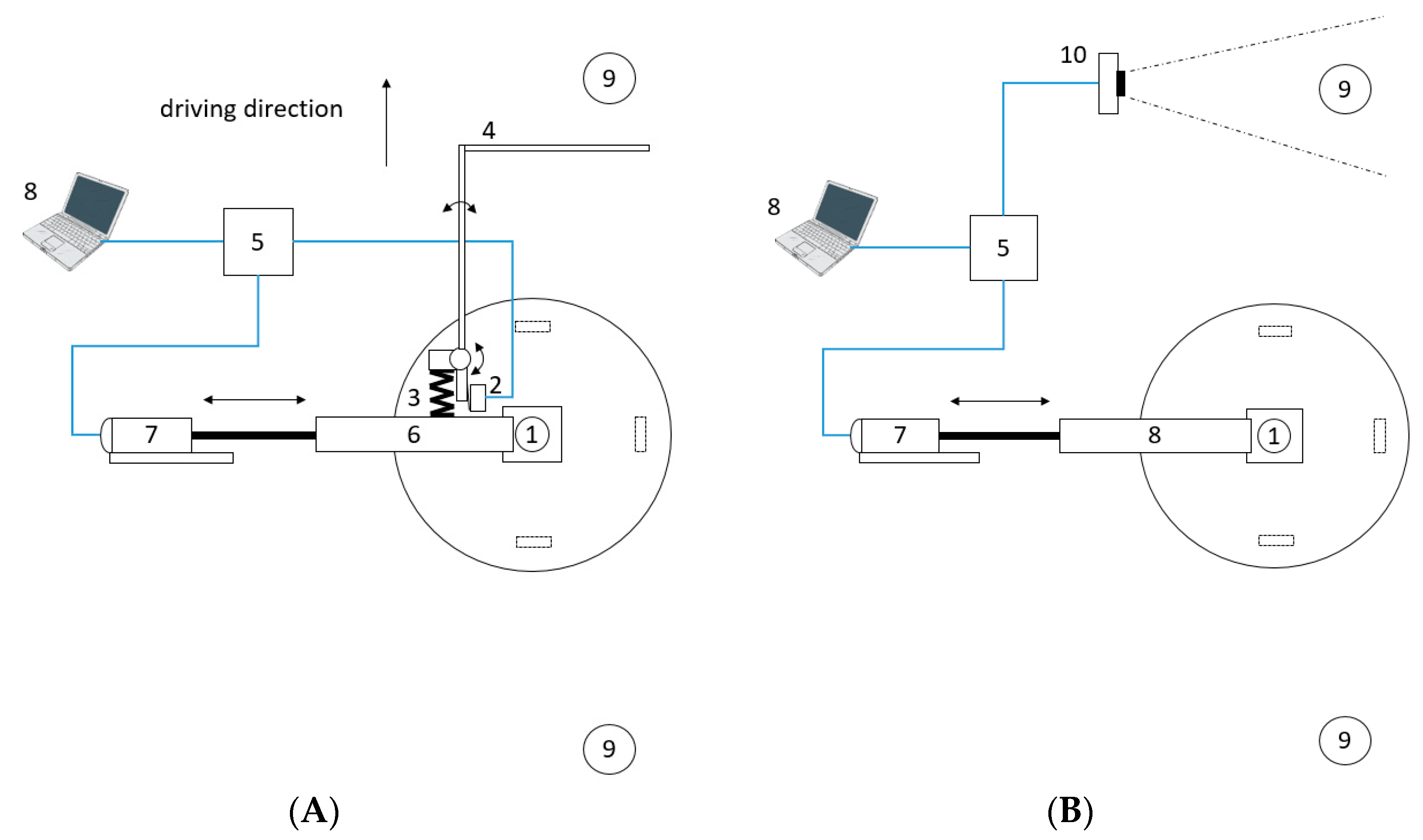
−1. 11 plots were treated using a feeler and the remaining 11 plots were treated while detecting the poles with the sonar sensor. The position of the sonar and the feeler was placed 0.5 m before the weeder, so that the implement could move out of the way even without stopping the robots forward speed. The goal distance between the robot and the row was fixed to 0.15 m in the row following software. When a pole was detected, the electric actuator shifted the rotary out of the row, to prevent damage to the poles. As soon as the pole was passed, the actuator got shifted back inside the row. The linear motor used for the side shift had a maximum speed of 68 mm/s with no load and 52 mm/s at maximum load. On average this resulted in a travel speed of 60 mm/s of the linear LA36 actuator. As the implement was set up to move 0.15 m to the intra row area, at least a time difference between pole detection and arrival of the tool of 2.5 s were needed. As the traveling speed of the robot was fixed to 0.16 m/s, it was necessary to detect the tree at least 0.4 m before the implement. For gaining some buffer, the pole detection was set up at a distance of 0.5 m. The time delay for the shifting mechanism was fixed to 2.5 s in the software to get as close as possible to the poles and therefore to potential trunks. The following
Figure 3 describes the mechanical and electrical components of the two control methods using the sonar sensor and the feeler.
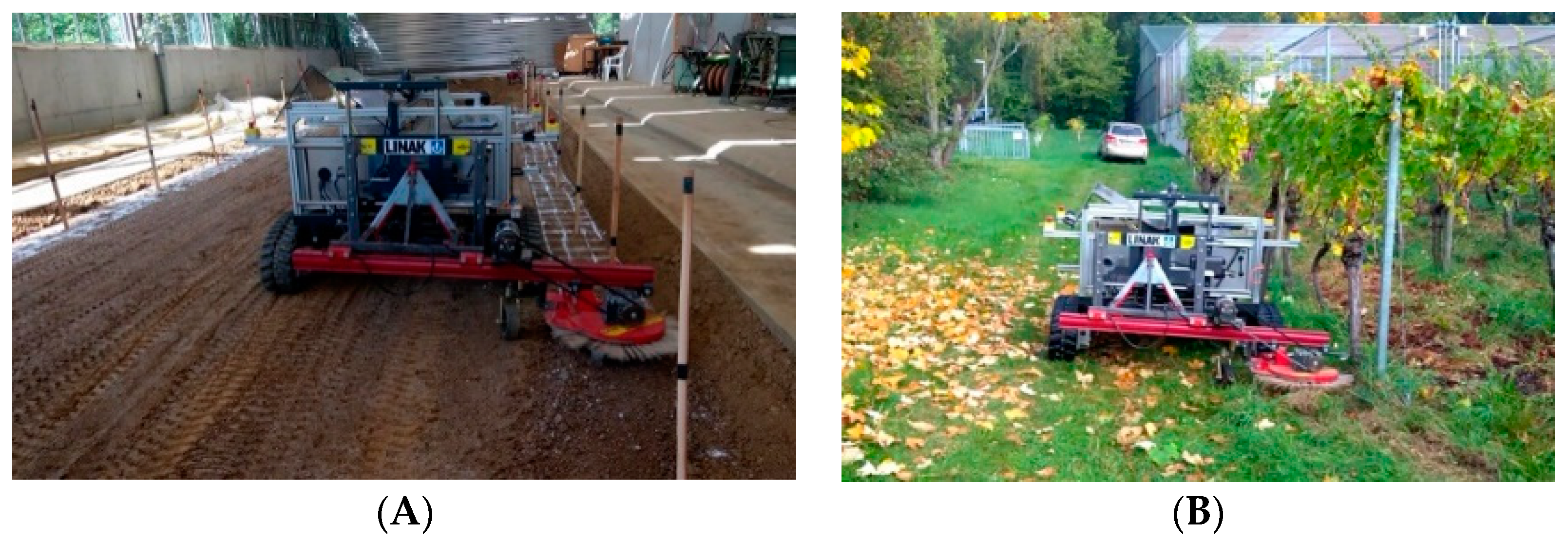
For each treatment, the power consumption and the accuracy of the processing procedure were evaluated estimating the treated and the non-treated area. The better control method tested in the indoor laboratory was evaluated at the vineyard of Hohenheim University (48.710115 N, 9.212913 E) on 9 October 2018 (see
Figure 4). The following figure shows the two different test areas for the autonomous weeding robot.
3. Results and Discussion
3.1. Comparison of Feeler and Sonar
Over the plots of the indoor trial, the soil moisture varied between 13.1% and 7.4% by volume. The shear stress varied between 59 and 82 MPa. The penetration resistance varied between 2 and 4 MPa for the depths of the first 10 cm. The detailed results of the soil physical properties for the laboratory test can be found in
Table 2.
3.2. Efficiency of the Control Algorithm
The percentages of the tilled area between the poles (trunks) were used as parameters to indicate the efficiency of weed control in the current study.
Table 2 indicates that the sonar treatment performed better than the feeler. Only at the plots t9 and t11 the feeler performed better than the sonar. In all other plots sonar performed equal or better compared to the feeler solution. The overall performance of both methods was at least over 50% of the intra-row area, at some plots reaching a tilled area of almost 100%. The average of the tilled area for the feeler was 65% and for the sonar it was 82%.
The results of the tilled area indicated a high success rate of both methods. However, the sonar control method outperformed the feeler control. One reason for this was that the sonar signals of the poles could directly be converted to a control message. The feeler sometimes got stuck at the poles for some seconds, causing wrong signals to the actuator and made it hard for the software to define the exact pole position. Additionally, the long lever of the feeler caused vibrations, sometimes triggering the switch even when there was no pole. With no other disturbances e.g., of weeds and branches, the sonar worked reliably and without any failure. Therefore, it was suggested, to test this control method under outdoor conditions later on.
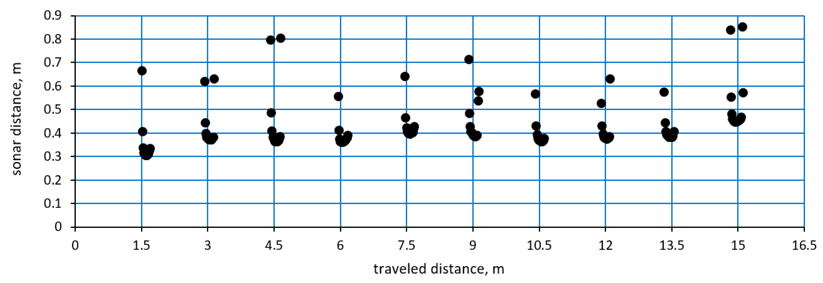
The signals from the sonar sensor over the travelled distance in the soil bin can be seen in the following
Figure 5. The gained signals showed a peak at the pole positions. At the beginning the sonar values hit the edges of the poles, causing wrong distance signals. This effect could be seen at both sides of the poles. However, the minimum value of the sticks was quite accurate in distance and position. The signals always formed small peaks with similar values. This shape could be used for further filtering of the exact trunk positions in the future and separate high weed spots from trunks. All poles triggered at least one signal of less than 0.5 m distance, which triggered the side shift of the implement. Therefore, the sonar could detect all poles at the indoor test.
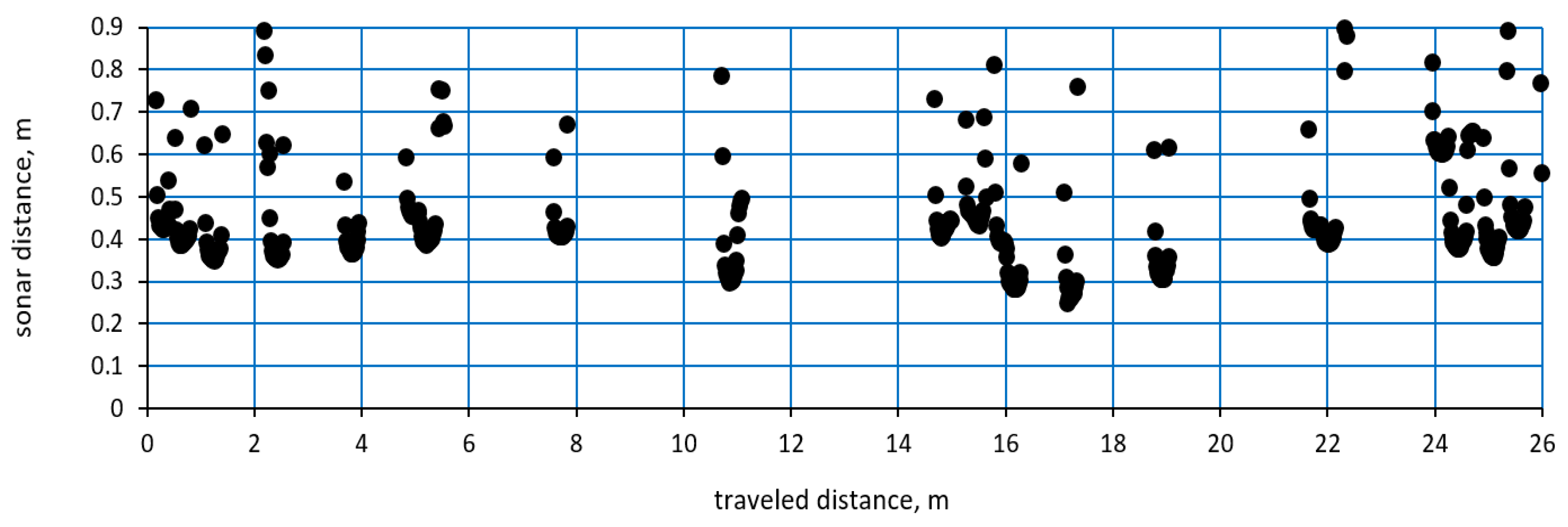
In the following outdoor test just the sonar detection was evaluated.
Figure 6 shows the sonar detections based on the test in the vineyard of Hohenheim University. In this case the trunks were not spaced out evenly like in the indoor tests. Sometimes individual trunks were missing, or were closer together (less than 0.5 m), causing that in this case the intra-row area could not be entered by the tilling device. Additionally, there were shoots and weeds causing disturbances. However, with small height adjustments of the sonar sensor, the system worked well in the outdoor vineyard. The linearity of the row was not given, because of curved trunks, as they were not in a straight line as the wooden poles.
However, all vines were successfully detected, causing no issues with hitting the vines basal area with the implement or similar. But the within-row spacing of the vines was not always suitable for the 0.3 m diameter electric weeder head, as there was not enough space to enter the intra row area between some trunks. Some of them were close to 0.5 m distance, causing the system to stay outside of the crop row. Using different sizes of weeder heads would solve this issue. At the spots with bigger gaps, the system performed well and did not cause any problems at all. When analyzing the tilled area of the outdoor test using the ImageJ software, the min value reached 57%, the max values 98% of the tilled area. Areas where the tiller head could not enter were excluded from the analysis.
It could be shown, that the outdoor test did perform well under the given circumstances. However, the environment was not sloped, which could bring more issues to the trunk detection. At high angles, shoots and leaves could hang more into the area of the sonar sensor. The automatic trunk detection would work in ordered and well cultivated vineyards. More complex examples would need an additional tree detection system like a laser scanner or camera, which could filter out the sonar values depending on the environment and context. Additionally, the trajectory of the implement could be planned dependent on the robot forward speed. This could make a more flexible path planning possible. However, the tilled area and the detection rate of the system were sufficient for the evaluated test area.
3.3. Power Requirement for the Autonomous Robot
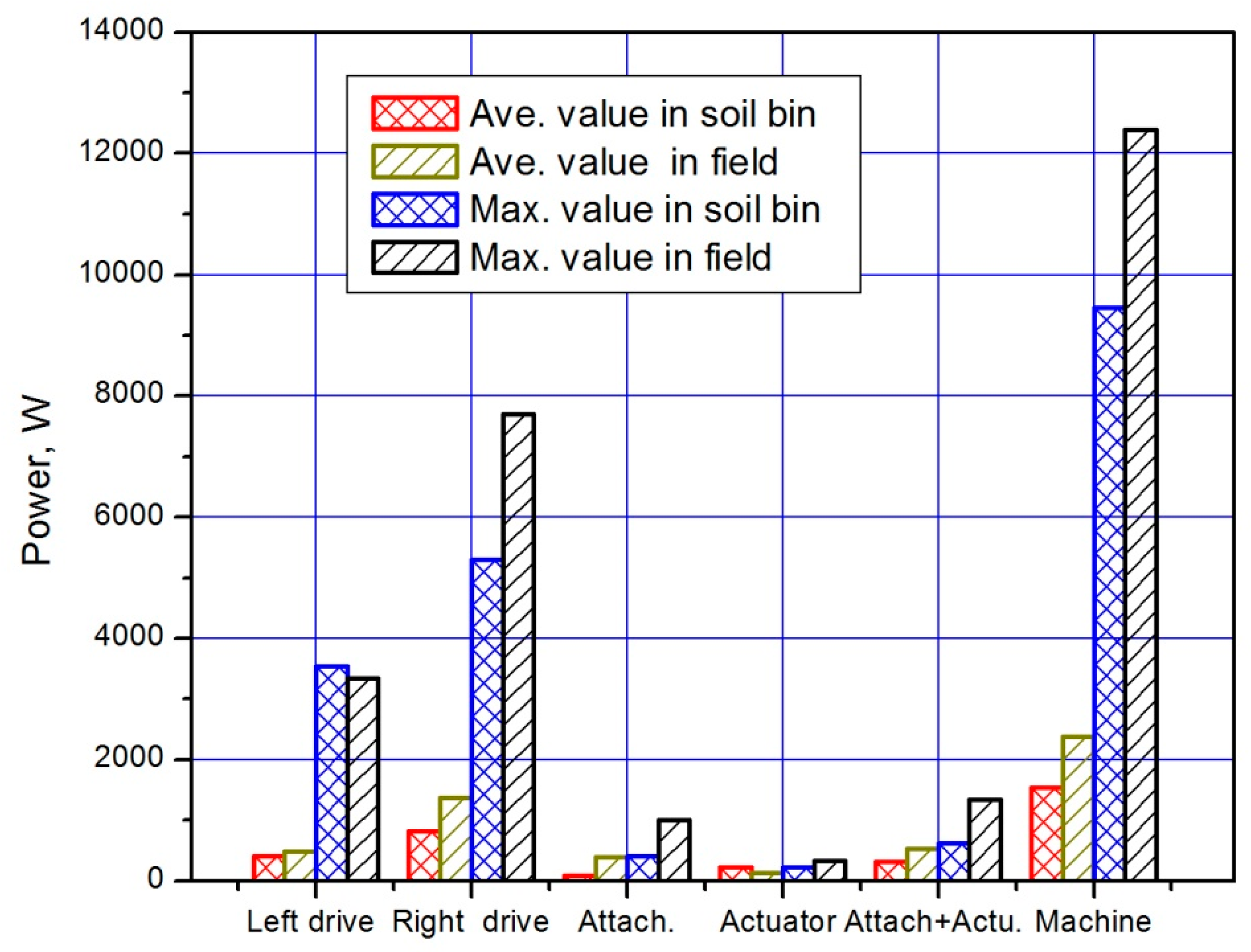
The maximum and average power requirement for the implement guidance, actuator motor and belt drive of the autonomous robot is shown in the following
Figure 7. In the indoor test, the power consumption increased with higher soil penetration resistance and shear stress. The overall power consumption for the implement was smaller than in the outdoor test. Here, an additional factor was the vegetation layer of weeds, which caused higher power consumption. Because of the implemented algorithm for limiting the working depth depending on the implement motor current, the power consumption peaks in the outdoor test were smaller than in the indoor test. When the soil in the indoor experiment would be compacted more, this difference between indoor and outdoor power consumption for the implement could be equalized.
In all tests the right drive motor of the robot needed more power than the left one. This was quite logical, as the implement was attached to the right side of the robot. The inertial forces of the tiller caused the robot to move to the right. To overcome this momentum, the row follower sent correction signals to the drive motors, forcing the right motor to consume more current. This effect could be seen at all performed tests. In the outdoor experiment, the slope of the tested area was not completely horizontal, causing higher power consumption for the drive motors. The overall power consumption of the machine was 1.8 KW in the soil bin and 2.2 kW in the outdoor field experiment. This would allow this machine with the given battery power to work around 8.1 h and 6.6 h depending on the slope and weed density. With a fixed speed evaluated in the experiments, the system could perform an intra-row weeding of 500 m/h.
When comparing the power consumption of the whole machine with the official power requirement provided by the rotary tiller manufacturer, the energy reduction is immense. The official power requirement for the tiller was set up with 8.1 kW by the company. Comparing the power consumption of the whole robot, the savings are more than 5.9 kW, meaning a 73% energy reduction. When we just compare the attachment, a 1 kW motor was enough to drive the implement in the performed experiments. When driving the robot system in a sloped environment, the power consumption of the drive motors would increase. However, it is expected, that the power consumption of the actuator would not differ in sloped environments.
3.4. Outlook
It could be shown that with an electrical implement a high power reduction could be possible, even when using commercial weeding tools. Combined with autonomous robots, this system could be highly energy efficient and sustainable. However, the system could be improved in the future. When using a higher speed for the linear side shift control, the overall speed of the machine could be increased, depending on the rotary speed of the rotary tiller and the side shift performance. Additionally, the tillage quality of the system could be increased, when the robot would stop at each trunk, to move the rotary weeder out of the row. Afterwards the robot could move a little bit forward and move the tool back into the row as soon as the trunk has passed. This would result in a rectangular trajectory, just excluding the trunk. Between the trunks, the speed could be increased until the next trunk is detected.
A different solution for detecting the trunks could be to use the information of the navigation laser scanner in front of the robot. Together with the odometry value, the software could increase the accuracy and plan the best trajectory for the implement based on speed, trunk spacing and weed density. This could help optimize path and work quality for weeding tasks in vineyards and orchards. In combination with a feeler or a sonar sensor this information could be filtered and optimized. This could help to increase the robustness and to not be disturbed from shoots and higher weeds.


