Article

Experimental Investigation of Wave-Induced Forces on a Large Quasi-Elliptical Cylinder during Extreme Events

1
China Merchants Chongqing Communications Technology Research and Design Institute Co., Ltd., Chongqing 400067, China
2
Department of Bridge Engineering, School of Civil Engineering, Southwest Jiaotong University, Chengdu 610031, China
3
State Key Laboratory of Mountain Bridge and Tunnel Engineering, Chongqing Jiaotong University, Chongqing 400074, China
4
Department of Bridge Engineering, School of Civil Engineering, Chongqing Jiaotong University, Chongqing 400074, China
*
Authors to whom correspondence should be addressed.
J. Mar. Sci. Eng. 2022, 10(4), 540; https://0-doi-org.brum.beds.ac.uk/10.3390/jmse10040540
Submission received: 16 March 2022 / Revised: 4 April 2022 / Accepted: 12 April 2022 / Published: 14 April 2022

Abstract

:
Large quasi-elliptical cylinders are extensively used in ocean engineering. To enhance a better understanding of the hydrodynamic wave force on such quasi-elliptical cylinders during extreme events, a series of experiments on extreme wave interaction with a quasi-elliptical cylinder were conducted. A series of waves with various wave heights, wave periods, and wave incident directions were tested to investigate the wave parameter effect and wave directionality effect on the wave forces on the quasi-elliptical structure. The experimental results indicate that the extreme wave-induced forces on the quasi-elliptical cylinder are strongly correlated to the wave period and wave incident direction. The peak forces on the quasi-elliptical model do not vary monotonically with the increasing wave period but show an increase followed by a decrease. Both the longitudinal and transversal forces are significantly increased when the wave incident direction changes from 0° to 45° and the wave directionality effect is enhanced when the wave period is decreased. Additionally, the inertial force equation was applied to the wave force estimation for such quasi-elliptical cylinders, and the inertia coefficient CM was fitted based on the experimental results of α = 0°.

1. Introduction

With the booming demand for transportation, lots of coastal bridges have been constructed in recent years. Large-scale cylinders with quasi-elliptical cross-sections are widely used in sea-crossing bridge construction due to their economic benefits over the large circular cylinders and their better performance in wave diversion than large rectangular cylinders. For example, this kind of cylinder is often used as the caisson foundation and pile cap for coastal bridges. In recent years, extreme hydrodynamic events, such as hurricane Ivan in 2004, hurricane Katrina in 2005, the Indian Ocean tsunami in 2004, and the Tohoku tsunami in 2011, cause extensive damage to coastal bridges [1,2,3,4,5,6,7,8,9,10,11,12,13,14,15]. As the bridge caisson foundations and pile caps are submerged into the seawater or close to the sea level, they are exposed to extreme waves, and prone to damage under the action of extreme waves. Thus, understanding and estimating the hydrodynamic forces exerted on such quasi-elliptical cylinders during extreme hydrodynamic events are of significant engineering relevance to the safety of coastal bridges.
The wave forces on cylinders with circular cross-sections have been widely studied. Basically, according to the circular cylinder scale (D/L, where D is the diameter of the cylinder and L is wavelength), there are two main methods for estimating the wave forces. One is the Morison equation [16], which is suitable for small-scale circular cylinders (D/L < 0.2). However, for large-scale circular cylinders (D/L > 0.2), as the presence of the body would cause significant diffraction waves, the Morison equation is not applicable anymore. Based on diffraction theory, Havelock [17] and MacCamy and Fuchs [18] derived analytical solutions for estimating wave forces on such large-scale circular cylinders in water with infinite and finite depth, respectively. Numerous experiments on wave interaction with the large-scale circular cylinder have been conducted [19,20,21,22]. In these experiments, the relative cylinder scale (D/L) and wave steepness (H/L) covered a wide range. The comparisons of their experimental results with the calculated value by MacCamy and Fuchs’s approach [18] verified the validity of this approach and indicated that this approach has wider application conditions.
Compared with the studies focusing on the circular cylinders, studies focusing on a large-scale cylinder with a quasi-elliptical section are relatively limited. Based on the finite difference method and volume of fluid (VOF) method, Wang et al. [23] established a 3D numerical model to investigate the wave forces on a quasi-elliptical cylinder. By varying the relative wave height H/d, relative cylinder width kD, and relative length-width ratio B/D in the numerical model, the numerical results indicated that the relative wave height (H/d) significantly influences the longitudinal force and the relative length-width ratio (B/D) significantly influences the transversal force. Using a similar numerical model, Wang et al. [24] studied the wave forces and wave run-up on a perforated quasi-elliptical cylinder. Compared with the solid quasi-elliptical cylinder, the wave forces and wave run-up on the cylinder are reduced by the perforated effect. Then, Ren et al. [25] and Ren et al. [26] extended the single quasi-elliptical cylinder to multiple quasi-elliptical cylinders. The wave forces on the multiple quasi-elliptical cylinders have been explored, considering the influence of wave height, wave period, wave incident direction, and the spacing between the quasi-elliptical cylinders. Wei et al. [27] conducted a series of experiments on wave-current interaction with a bridge tower, which has a quasi-elliptical caisson foundation. The wave-only, current-only, and wave-current induced combined forces on the quasi-elliptical foundation were presented. Except for the numerical and experimental investigations, Liu et al. [28] and Liu et al. [29] proposed analytical solutions for estimating the wave forces on a bottom-mounted and truncated cylinder with arbitrary cross-section, respectively. Their solutions are based on the condition that the radius function of the cylinder can be expanded into a Fourier series. Wei et al. [30] developed a force prediction formula by superposing the theoretical formula for estimating wave forces on a large circular cylinder (derived by MacCamy and Fuchs [18]) and the empirical formula for estimating wave forces on a large rectangular cylinder.
In the actual marine environment, extreme waves always obliquely attack the structures. The oblique wave-coastal structure interaction problem, such as oblique wave-coastal bridge interaction [31,32], and oblique wave-breakwater interaction [33,34] have been widely studied. As the geometry of the large quasi-elliptical cylinder is not totally symmetric, the wave directionality effect should be taken into account when estimating the wave forces on such large-scale quasi-elliptical cylinders. Among the above studies, only Liu et al. [29] and Ren et al. [26] considered the influence of wave incident direction.
To better understand the hydrodynamic performance of the large-large scale cylinder with a quasi-elliptical section, and investigate the effect of extreme wave height, wave period, and wave incident direction on the wave forces, a series of experiments on extreme wave interaction with a quasi-elliptical cylinder were conducted. The nonlinear regular wave was adopted to simulate the extreme wave, and four wave heights, six wave periods, and four wave incident angles were considered. The experimental setup is described in Section 2, involving facilities, test cases and test procedures. In Section 3, the experimental results under the conditions of normally incident waves are presented. The inertial force equation was applied to the wave estimation for such a quasi-elliptical cylinder and inertia coefficient CM was fitted based on the experimental results. Then, the oblique wave-induced forces are presented and the wave directionality effect is discussed. In Section 4, conclusions and suggestions targeted at the large-scale cylinder with a quasi-elliptical section are drawn.

2. Materials and Methods

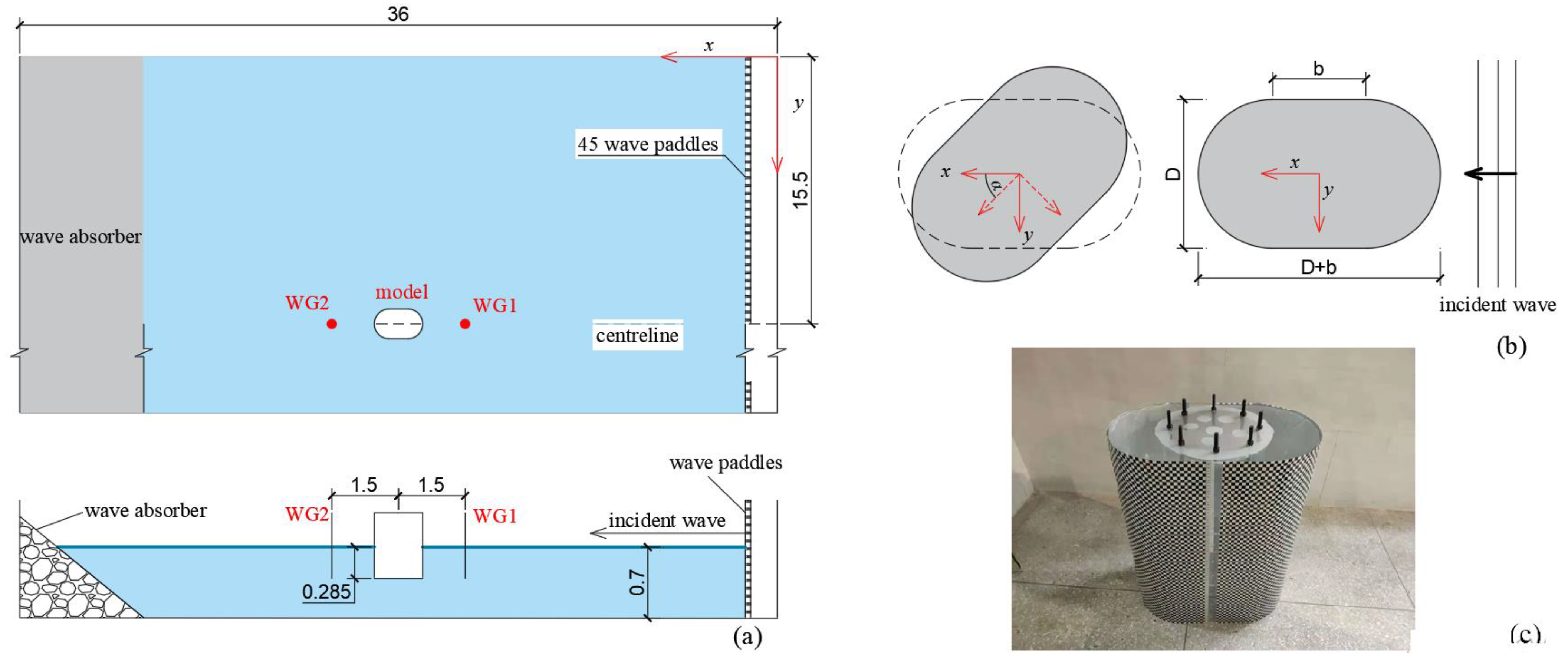
2.1. Facilities and Instrumentation

The experiments were conducted in the Underwater Tunnel Laboratory, China Merchants Chongqing Communications Technology Research and Design Institute Co., Ltd., China. The wave flume is 36 m in length, 31 m in width, and 3 m in height, as seen in Figure 1a. The flume is equipped with a piston-type wavemaker system. The wavemaker system consists of a computer controlled system, servo drivers, servo motors, and 45 wave paddles. The 45 wave paddles are installed at the right end of the flume along the whole flume width and driven by the computer controlled system so that one-dimensional wave environments can be generated. The wavemaker system is able to generate various wave environments, such as linear regular wave, nonlinear regular wave, and solitary wave. The sponge wave absorbing-beach is positioned at the left end of the wave flume to reduce the wave reflection. It is tested so that the absorption capacity of the wave absorber is more than 92% in the main wavelength range. A steel frame is equipped at the top of the wave flume to fix the test model. The test frame can slide in three directions to adjust the model position. A detailed description of the wave flume can be found in another study [35].
Two wave gauges (WG1 and WG2) with a sampling rate of 200 HZ and 0.1 mm spatial resolution are installed 1.5 m ahead and 15 m behind the tested model. A 3-component dynamometer is mounded between the tested model and the steel frame to measure wave forces on the model. Force data are sampled at a rate of 200 HZ, which is sufficient to capture the peak forces.

2.2. Test Model, Test Cases and Test Procedure

The design of the tested model was inspired by a foundation for a sea-crossing bridge in China. The prototype foundation has an elliptical section with dimensions of 68 × 41.8 m, combining a central rectangle of 26.2 × 41.8 m, and two external semi circulars with a diameter of 41.8 m. Considering the flume dimensions and abilities of experimental facilities, the tested model was designed according to the Froude similarity using a 1:100 geometric scaling. Figure 1b,c displays the scale model with characteristic parameters of D = 0.418 m and b = 0.262 m. The height of the scale model is 0.7 m, which is high enough to prevent wave overtopping. The scale model is made of polymathic methacrylate, and its interior is empty, and the exterior is closed. At the top surface of the model, there are eight pre-reserving bolts used to fix the model, see Figure 1c. The model is mounted 15 m downstream of the wave paddle and fixed by attaching its top surface to the steel frame through the 3-component dynamometer. In the experiments, the quasi-elliptical model is partially submerged into the water, with constant submerged depth Sd = 0.285 m for all the tested cases.
The prototype wave height of 6 m, 7 m, 8 m and 9 m and the prototype wave period 8.5 s, 9.0 s, 9.5 s, 10.0 s, 10.5 s, and 11.0 s were chosen to simulate the extreme waves. The corresponding tested wave height (H = 0.06 m, 0.07 m, 0.08 m, and 0.09 m) and wave periods (T = 0.85 s, 0.90 s, 0.95 s, 1.00 s, 1.05 s and 1.10 s) are listed in Table 1. According to the wave parameters, H/gT2 and d/gT2, most of the test waves are found in the range of the third-order Stokes wave and some waves correspond to the second-order Stokes wave, as shown in Figure 2.
In the actual marine environment, the wave height and wave period but also the wave incident direction are varied. To simulate the multidirectional extreme waves in the actual marine environment, four wave incident angles of α = 0°, 15°, 30°, and 45° are considered. As shown in Figure 1b, the wave incident angle α is defined as the angle between the wave propagation direction and the long centerline (D + b) of the model. As the wave paddles are installed on the left side of the wave flume, the generated wave could propagate only along the x-axis of the wave flume. Thus, for the condition of α = 0°, the long axis (D + b) of the model is parallel to the x-axis of the wave flume. For other conditions with α = 15°, 30°, and 45° the quasi-elliptical cylinder is rotated by 15°, 30°, and 45° clockwise based on the center point to simulate the interaction of obliquely incident waves with the quasi-elliptical cylinder.
Before the quasi-elliptical cylinder is mounted into the flume, the wave surface elevations at the model center position were monitored to verify the quality of the generated nonlinear regular waves. After that, the model was mounted into the flume, and the wave-induced forces on the quasi-elliptical model were measured. The time of the generating wave was set to 25 s, which ensures a trail of waves act on the model and fewer reflected waves act on the model.
To ensure the accuracy and repeatability of the experiments, each case, where the wave height, wave period, and wave incident angle remain constant, was repeated three times. The results of wave heights and forces are the averages of the statistical analysis of the three trials. Any repeated test with a variation in maximum force or wave height of more than 5% was not used.

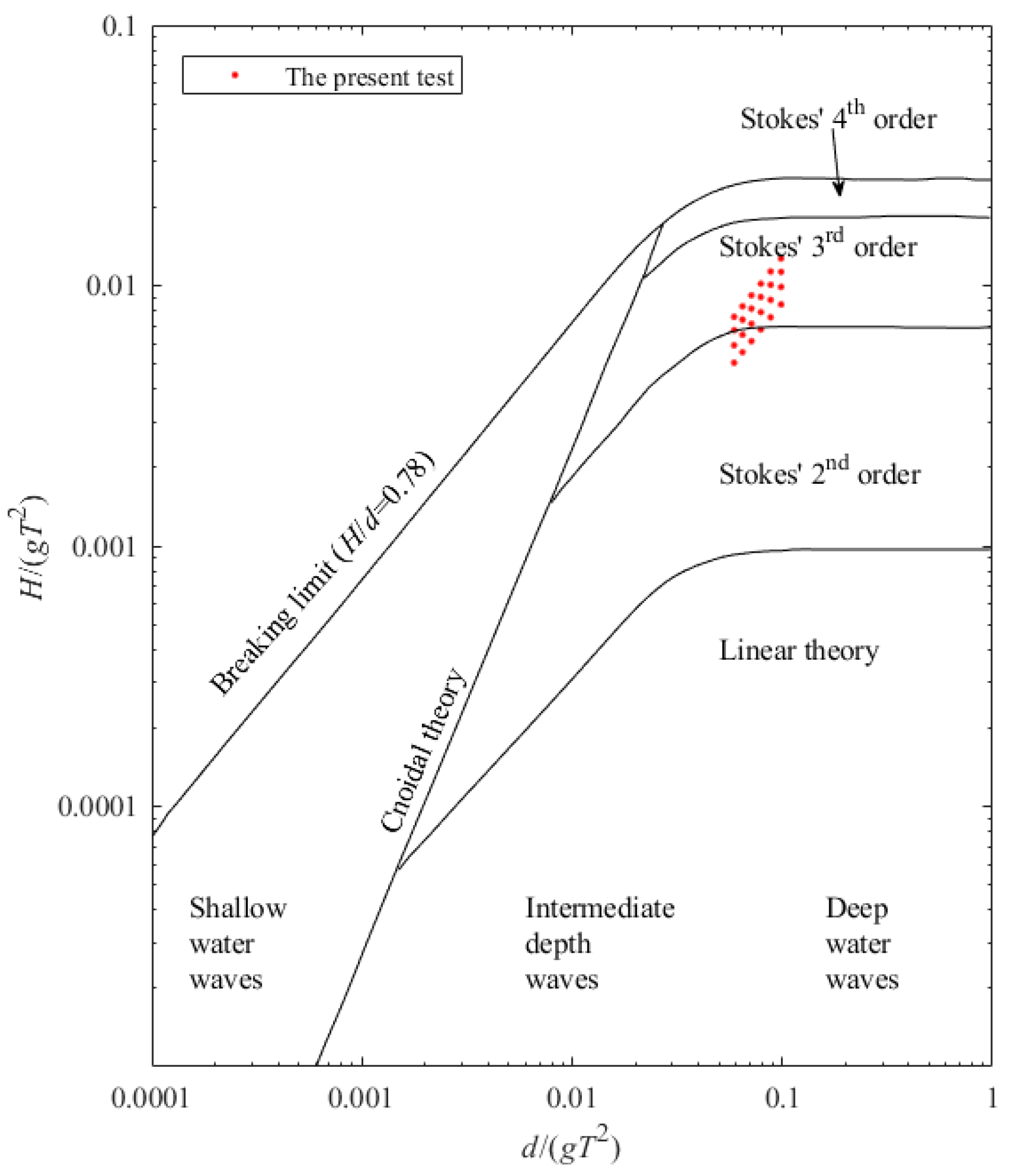
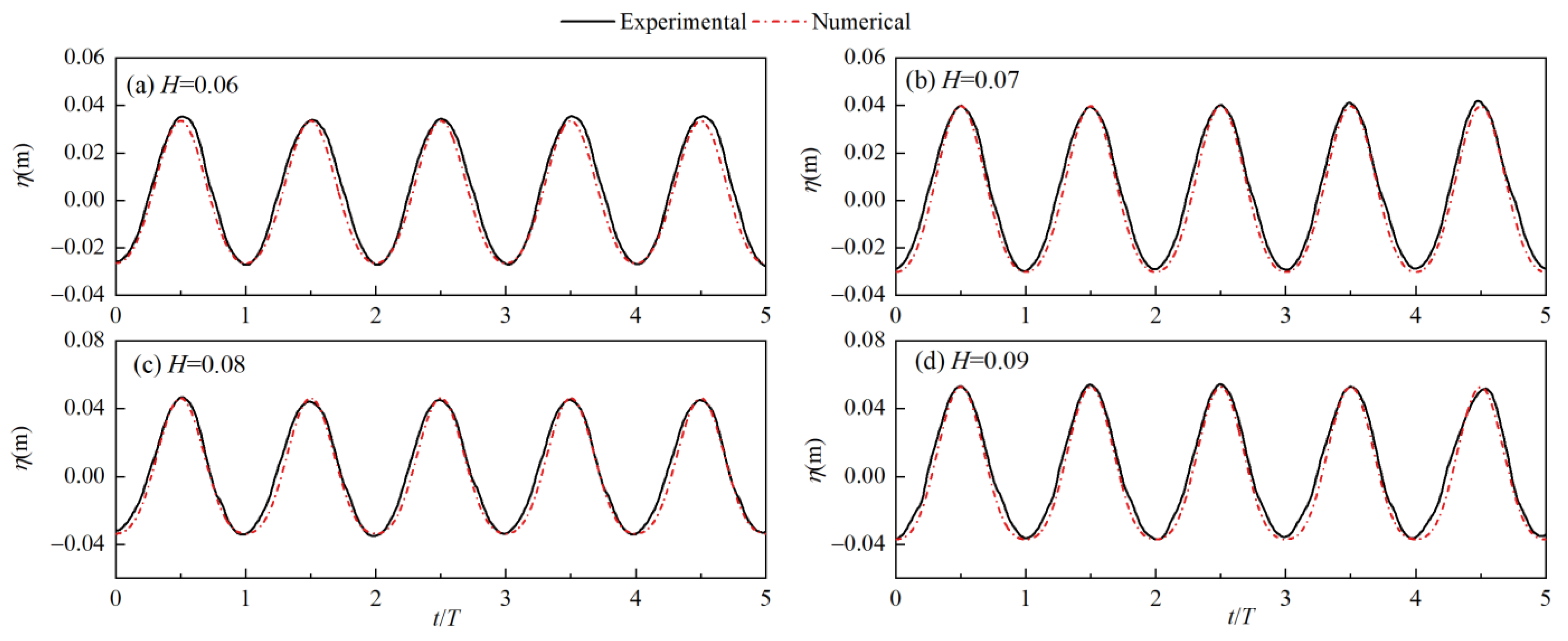
2.3. Validation of Regular Wave Train in the Flume

The wave surfaces measured at the model center without the round-end cylinder are compared with the theoretical wave elevations calculated by the 2nd and 3rd order Stokes wave theory. As shown in Figure 3, the generated waves are sable within the whole reported time-domain and good agreements are observed between the measured and theoretical results. It indicates that the wavemaker is capable of generating good-quality nonlinear regular waves. For all the cases listed in Table 1, the relative errors between the generated wave height and aimed wave height are within ±3%, satisfying the experimental requirements.

3. Results

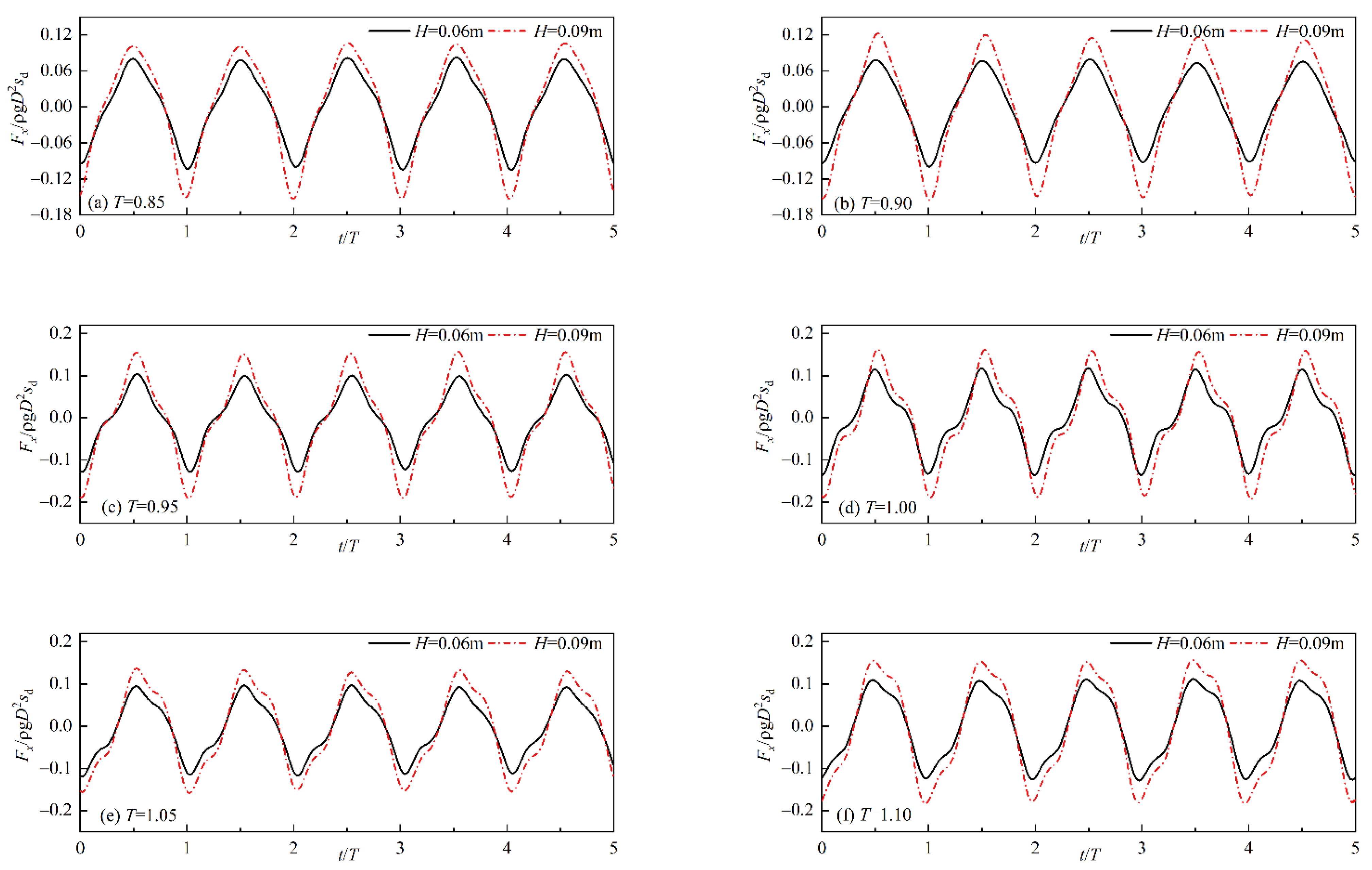
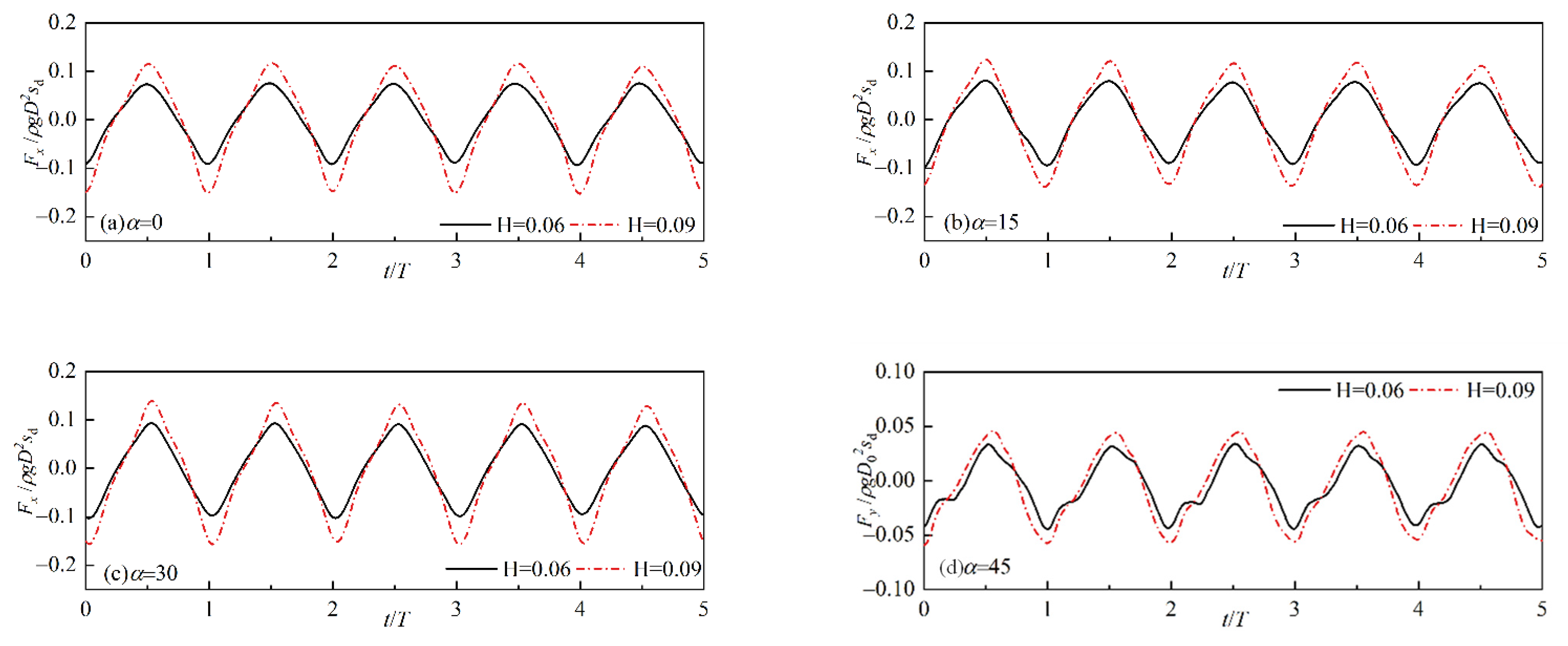
3.1. Effect of Wave Characteristics

Figure 4 shows the time histories of the longitudinal force (Fx) on the quasi-elliptical cylinder for several typical cases. The positive value and negative value represent the forward force and backward force along the x-axis, respectively. The longitudinal force oscillates between the positive and negative peak values periodically with the wave action. Within one period, as the wave hits on the model, the longitudinal force rapidly increases to a positive peak. Then, as the wave crest passes through the model, it decreases to a negative peak and finally back to zero. The positive peak force is not totally equal to the negative peak force. The value of the negative peak is larger than the value of the positive peak, especially for the cases of a wave with a larger wave height and smaller wave period. For the case of H = 0.9 m and T = 0.85 s the negative peak value is almost 1.44 times the positive peak value.
Compared with the wave with a smaller wave height, the higher wave-induced force show similarity in the shape of the curve, but with a higher peak value. The higher peak value is caused by the larger action area and larger acceleration of the water particles. Compared with a wave with a smaller wave period, the wave force for the case with a larger wave period shows an obvious dissimilarity in the shape. For the cases of the wave with a smaller wave period (T = 0.85 s, 0.90 s), the force curve rapidly decreases to zero after reaching the peak values. However, for the cases of the wave with a larger period (T = 1.05 s, 1.10 s), the force rapidly raises from zero to peak value, then gradually decreases to a stage with a relatively large value and finally rapidly decreases to zero. It makes the forces stay high for a longer duration. It is unfavorable for the stability of the structure because the stability of the structure not only depends on the magnitude of the force but also the lasting time of the force (mu = Ft, m is the mass of the structure, u is the velocity, F is the forces on the structure and t is the force lasting time).
Figure 5 shows the process of the wave acting on the quasi-elliptical model for the case of H = 0.9 m, T = 0.9 s. The camera is installed at the longitudinal centerline of the flume and 2 m upstream of the model. As seen in Figure 5a, an obvious diffraction wave is generated due to the existence of the large model. The diffraction wave and incident waves superimpose over one another and form a new wave field (Figure 5b). The newly formed wave hits on the model and a part of the wave runs up along the upstream side of the model (Figure 5c). Then, the wave crest passes away and the next wave arrives (Figure 5d).
The longitudinal positive peak force (Fx+) and longitudinal negative peak force (Fx) with a broad range of wave height and wave period are presented in Figure 6a,b, respectively. As observed previously, the higher wave causes both higher positive and negative peak forces due to the larger wave impact area and larger fluid accelerations. Additionally, it is observed that the positive peak force and negative peak force show a similar transformation trend with the increase of the wave period. Both the positive peak force and negative peak force increase first and then progressively decrease with the increasing wave period. The largest positive and negative peak force occurs at a period of 0.95 s or 1.00 s. The magnitude of the peak forces depends on the fluid acceleration and pressure difference between the front and rear semicircular surfaces of the quasi-elliptical model. For these critical periods, as the wavelengths are nearly two times the length of the model (D + b) when the wave crest hits on the front semicircular surface, the wave trough arrives at the rear semicircular surface, and thus the largest peak force occurs. For wave periods smaller than these critical periods, although the fluid accelerations are relatively large, the forces exerted on the quasi-elliptical model are smaller because the pressure difference between the front and rear semi-circular surfaces is smaller. For periods larger than these periods, the fluid accelerations are progressively smaller and thus the total forces become smaller.
The values of the negative peak force are compared with the values of the positive peak force. For all the cases shown in Figure 6, the negative peak forces are larger than the corresponding positive peak force, nearly being 1.16~1.44 times the positive peak forces. Thus, the nonlinear wave-induced negative peak force should be fully considered in the construction design of the quasi-elliptical structure.
As the large quasi-elliptical cylinder is extensively used in ocean engineering, it is critical for engineering applications, to estimate the peak forces on such structures. Although Liu et al. [28] and Liu et al. [29] have developed analytical solutions for estimating the wave forces on the cylinders with arbitrary cross-sections, the formulas are presented in a complex form. It is not simple and effective for practical engineering applications. Wei et al. [30] suggested an approximate analytical formula to estimate the regular wave-induced forces on a large quasi-elliptical structure. It is established based on the superposition of the theoretical formula of wave forces on a large circular cylinder (developed by MacCamy and Fuchs [18]) and the empirical formula of wave forces on a large rectangular cylinder (suggested by the Code of Hydrology for Harbor and Waterway (China) [36]). The approximate formula is proved to be efficient by comparing the predicted force with the experimental force. However, the formula is developed based on the perpendicular quasi-elliptical structure (the condition of incident wave angle α = 90°), and is inapplicable to the parallel quasi-elliptical structure (the condition of incident wave angle α = 0°).
For the parallel quasi-elliptical structure, as the wave action area in the longitudinal direction is identical to that of a circular cylinder with an equal diameter, one may expect that the peak forces on the quasi-elliptical cylinder could be roughly estimated by the force prediction method for a circular cylinder. Therefore, the measured peak forces on the quasi-elliptical cylinder are compared with the predicted peak forces on a circular cylinder with equal diameter to examine this expectation. The predicted peak force is calculated by the analytical solution developed by MacCamy and Fuchs [18]. By integrating the formula given by MacCamy and Fuchs [18] from the cylinder bottom z1 = dSd to the still water level z2 = d, the peak force can be obtained and it is transformed into an inertial force form:
F xmax = C M γ π D 2 H 8 sinh ( k z 2 ) sinh ( k z 1 ) cosh ( k d )
where CM is the inertial coefficient, γ is the unit weight of water, H is wave height, k is wave number, d is water depth, ω is wave frequency, z2 = d, z1 = dSd.
The comparison between the measured and predicted results is presented in Figure 7. The measured and the predicted peak forces are normalized with the parameter of γπD2H(sinh(kz2)-sinh(kz1))/[8cosh(kd)] and plotted against the parameter of D/L. It is observed that the measured positive peak value is close to the predicted value. However, as the negative peak force on the quasi-elliptical model is larger than the positive peak force, the negative peak value is underestimated, especially for the cases with small D/L. When D/L < 0.3, the negative peak value is underestimated by at least 40%. In practical engineering, this underestimation would result in unfavorable factors or even structural failure. To provide a more accurate prediction formula for such a quasi-elliptical structure, fitting analyses are carried out on the positive and negative peak values, respectively, as shown in Figure 8. The relationship between the inertial coefficients and the relative diameter (D/L) is obtained as follows:
C M + = 0.96 + 12.00   ( D / L ) 33.22 ( D / L ) 2
C M = 0.64 + 16.71   ( D / L ) 41.16 ( D / L ) 2
where CM+, CM is the inertial coefficient for estimating positive peak force and negative peak force, respectively, and L is the wavelength. Equations (2) and (3) can be used to estimate the peak forces on a parallel quasi-elliptical cylinder for the conditions of D/L within 0.2~0.4 for practical ocean engineering.

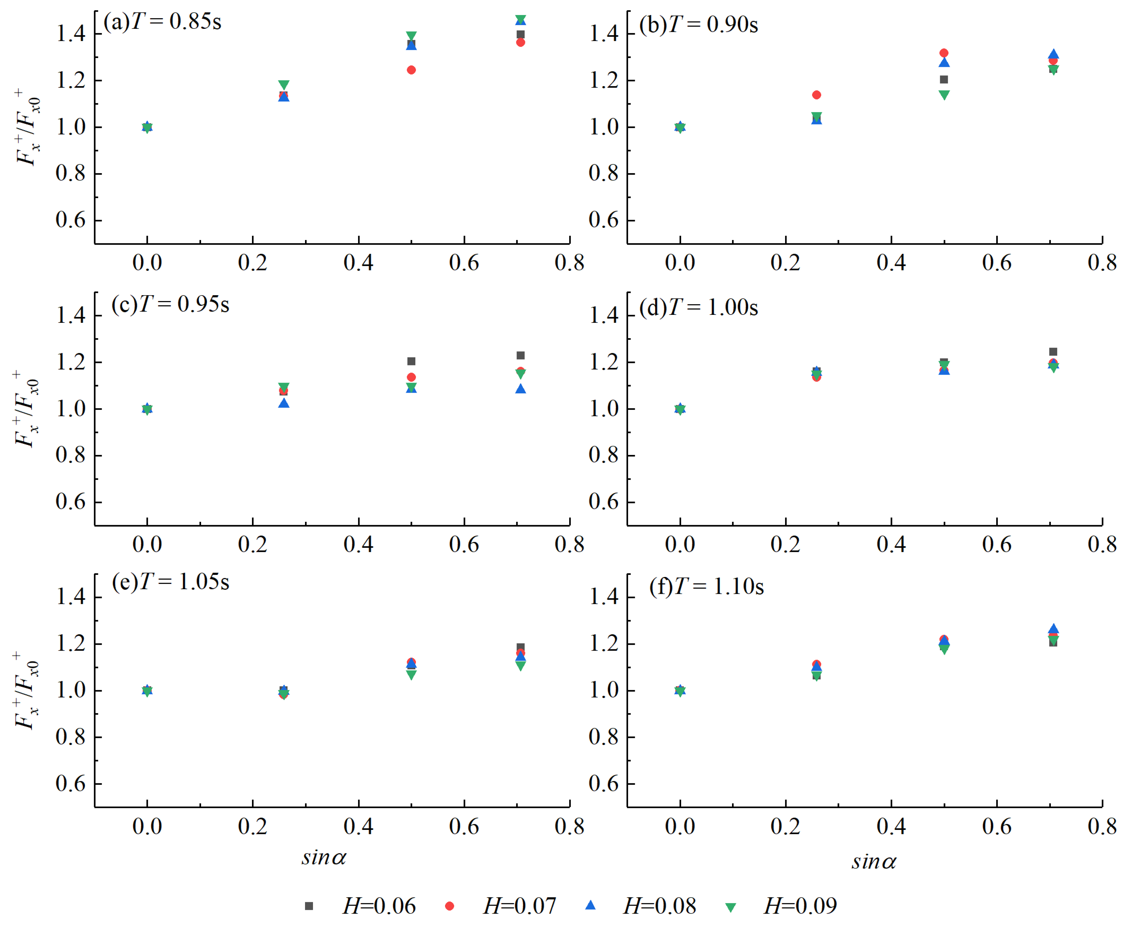
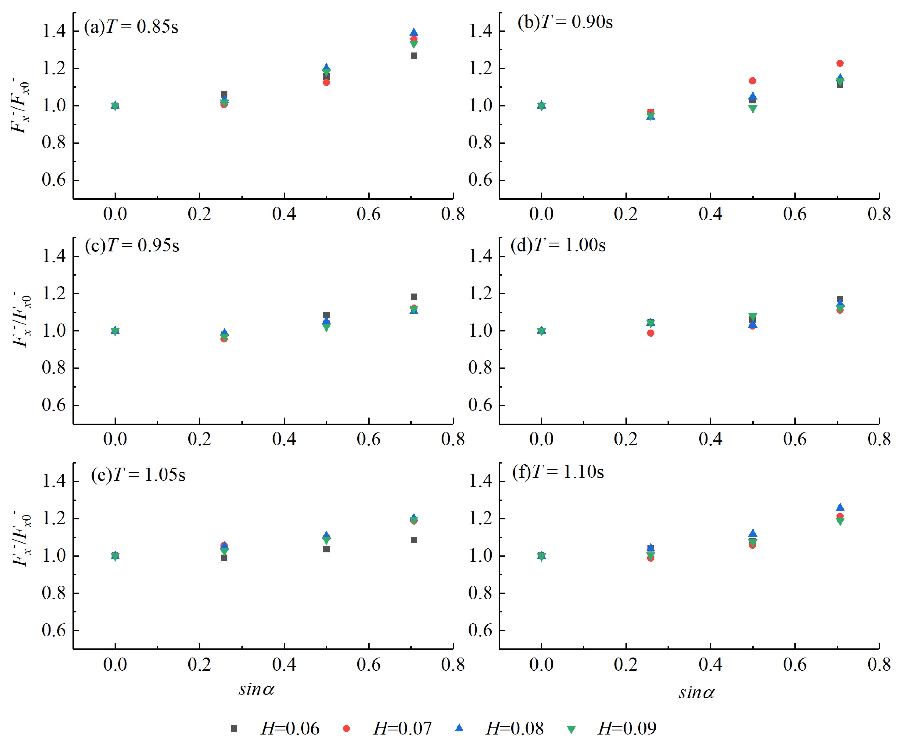
3.2. Effect of Incident Wave Direction on Logitudinal Wave Force

Figure 9 presents the time history of the longitudinal wave force for the typical cases of T = 0.9 s, H = 0.06 m and 0.09 m under four incident wave directions: α = 0°, 15°, 30° and 45°. Compared with the wave force under the condition of α = 0°, the wave forces under the condition of α = 15° and α = 30° do not show obviously dissimilarity in the shape of the curve. When the wave incident angle increases to 45°, the force on the cylinder presents a stagnation behind the positive peaks rather than rapidly decreasing to negative peaks. That is ascribed to the contribution of the wave force on the side surface of the quasi-elliptical cylinder. When the incident angle of the wave is larger, the wave acts on the seaward semicircle surface and the side surface of the quasi-elliptical cylinder in succession, making the longitudinal force stay high for a while after reaching the positive peaks. The longer lasting peak force may pose a threat to the safety of the cylinder because the structure safety not only depends on the magnitude of the force but also on the lasting time of the force. Thus, it should be carefully considered in the construction design of the quasi-elliptical cylinder.
Additionally, it is observed that as the incident angle increases, the absolute value of the positive and negative peak force presents an increasing trend in general. For the typical cases presented in Figure 9, when the incident angle α increases from 0° to 45°, the positive peak forces are increased by approximately 24.8% and 25.1% and the negative peak forces are increased by approximately 11.2% and 13.5%. As discussed previously, the wave force on the large cylinder is closely related to the fluid acceleration and the wave action area. With the incident angle increasing, the projected area perpendicular to the wave propagation direction increases. Thus, the value of the longitudinal peak forces increases.
The positive peak force Fx+ and negative peak force Fx measured under the conditions of an obliquely incident wave are normalized with the corresponding peak force Fx0+ and negative peak force Fx0 under the conditions of a normally incident wave to clearly show the wave directionality effect on the peak forces. Figure 10 and Figure 11 show the ratio of Fx+/Fx0+ and the ratio of Fx/Fx0 versus the sin value of the incident angle α, respectively. It is clearly seen from Figure 10 that the positive peak force almost linearly increases with the increase of the sin value of α. The projected area perpendicular to the wave propagation direction increases with the incident angle α, making more wave hits on the cylinder, and therefore, the positive peak force increases. The wave height seems to have little influence on the wave directionality effect. However, the wave directionality effect is enhanced when the incident wave has a smaller wave period. The relative increment of the positive peak force is more obvious for the cases with smaller wave periods. For the cases of T = 0.85, the coefficient positive peak force Fx+ under the condition of α = 45° even increases to 1.5 times the positive peak force Fx0+ under the condition of α = 0°. Therefore, when estimating the positive peak force on the quasi-elliptical model, the wave directionality effect should be taken into consideration.
From Figure 11, it is observed that the negative peak force Fx slightly increases or decreases when the wave incident angle α increases from 0° to 15°. Its influence can be neglected. However, when the wave incident angle is larger than 15°, the negative peak force improves significantly with increasing wave incident angle α. Similar to the positive peak forces, the directionality effect on the negative peak forces is also more obvious for the cases with smaller wave periods. For the cases of T = 0.85 s, the negative peak force improves 40% when considering the incident angle α = 45°. Therefore, when estimating the negative peak force on the quasi-elliptical model, the wave directionality effect should be taken into consideration when the wave incident angle is larger than 15°.

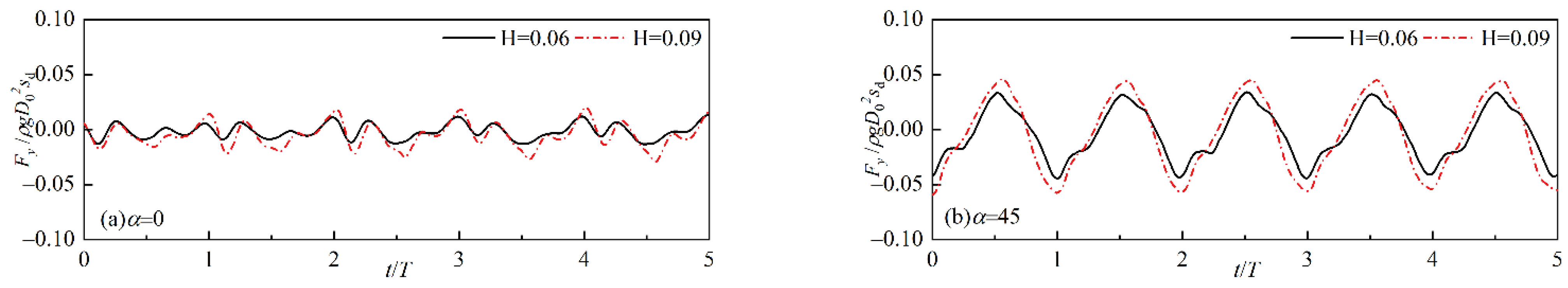
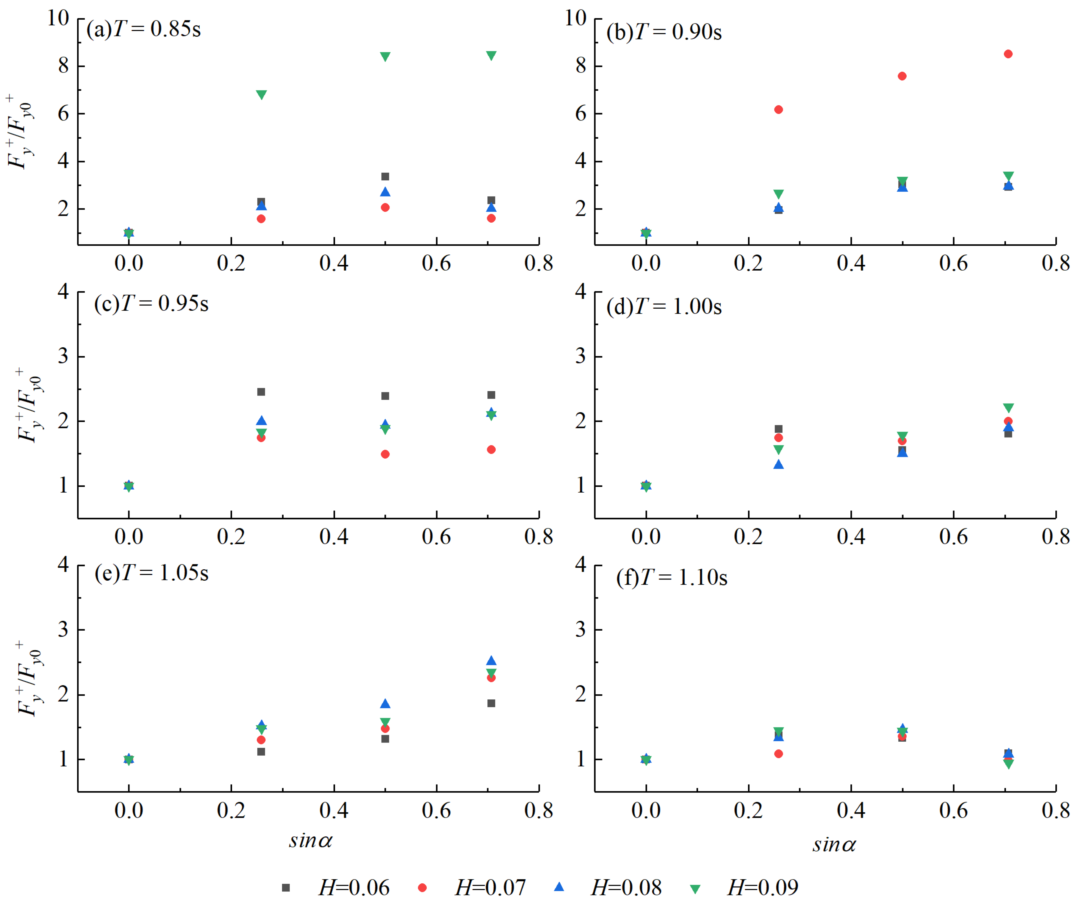
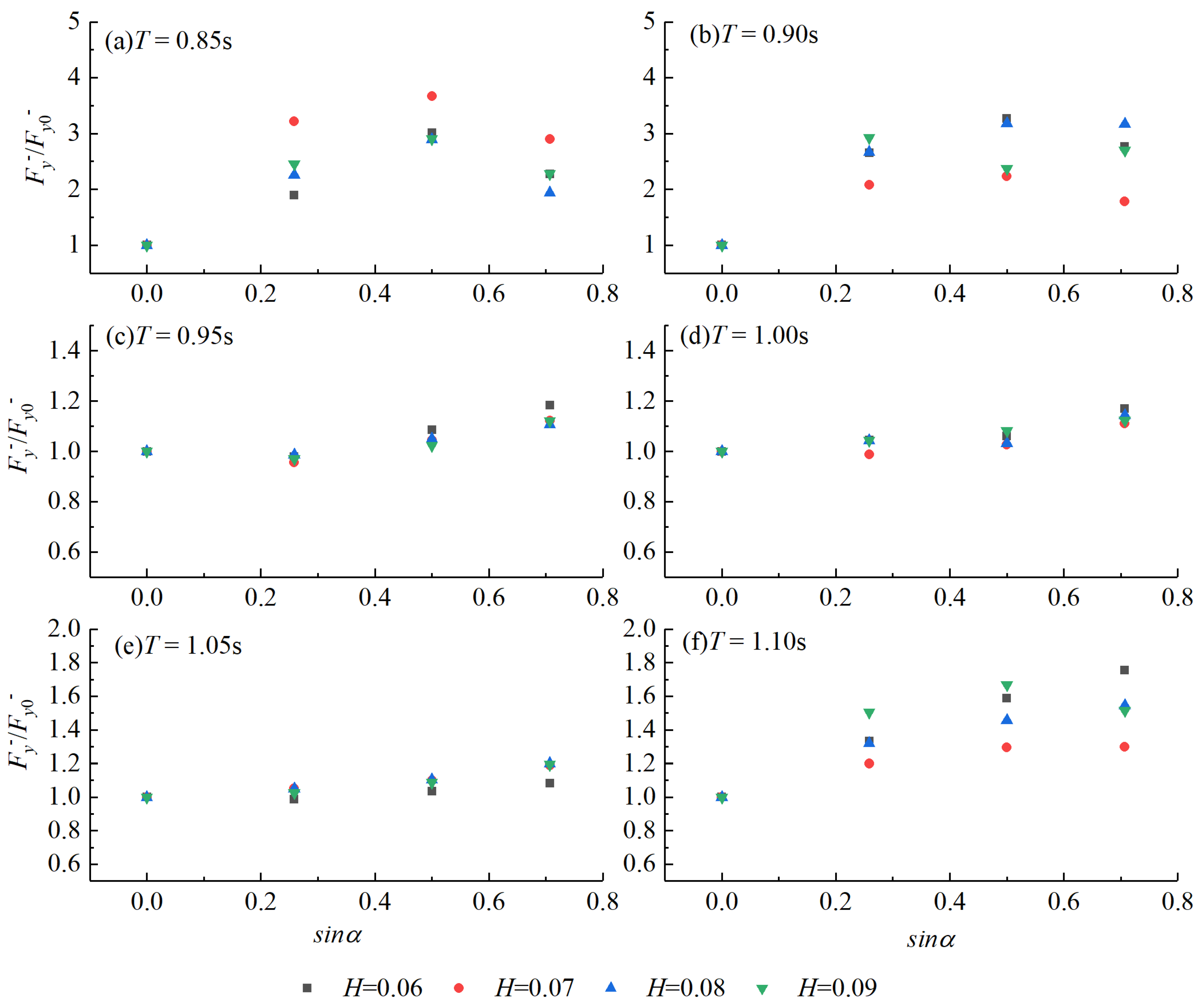
3.3. Effect of Incident Wave Direction on Transversal Wave Force

Figure 12 presents the comparison of transversal wave forces for typical cases with the wave incident direction α = 0° and α = 45°. Figure 12a shows that when the wave transports along the direction parallel to the wave long axis (α = 0°), the wave induced transversal force vibrates around 0 with a small amplitude. For the presented two typical cases, the peak values of transversal force are 10~15% of the peak values of longitudinal force when α = 0°. However, when waves obliquely act on the quasi-elliptical cylinder, as the wave action area increases the transversal forces increase. For the cases of α= 45°, the peak values of transversal force reach 40% of longitudinal peak forces. The large transversal force induced by wave oblique action seriously influences the structural safety of such large quasi-elliptical cylinders and should be fully considered during structural design.
To further illustrate the wave directionality effect on the transversal peak forces, Figure 13 and Figure 14 display the ratio of Fy+/ Fy0+ and the ratio of Fy/Fy0 versus the sin value of the incident angle α, respectively. In these figures, Fy+ and Fy are the positive and negative peak forces in the transversal direction and Fy0+ and Fy0 are the positive and negative peak forces in the transversal direction under cases of α = 0°. It is seen that both the positive peak forces and negative peak forces are seriously influenced by the wave incident angle. Compared with the wave directionality effect on longitudinal peak forces, the wave directionality effect on the transversal peak forces is more obvious. For some extreme cases, when the wave incident angle increases from 0° to 45°, the value of Fy+/Fy0+ can reach 8.5 and the value of Fy/Fy0 can reach 3.7. That means, with wave incident angle increases, the positive and negative peak forces in the transversal direction are obviously increased. Additionally, it is observed that the wave period has a great influence on the wave directionality effect. When the wave period decreases the wave directionality effect is enhanced, which is similar to the observation in longitudinal peak forces. Wave height also influences the wave directionality effect, but it does not present a clear trend.

4. Conclusions

An experimental investigation of extreme wave-induced forces on a large quasi-elliptical cylinder is presented. A series of extreme waves with various wave heights, wave periods, and wave incident directions are tested to investigate the wave parameter effect and wave directionality effect on the wave forces on the quasi-elliptical cylinder. Based on the experimental results, the following conclusions can be drawn:
(1) The longitudinal wave forces on the quasi-elliptical model are strongly correlated to wave height and wave period. The positive and negative peak forces in the longitudinal direction increase with wave height. Whereas they do not vary monotonically with increasing wave periods but show an increase followed by a decrease. Additionally, an increasing wave period makes the longitudinal forces stay at high values with a longer duration. It is unfavorable for the stability of the structure.
(2) The extreme wave-induced longitudinal negative peak forces on the quasi-elliptical cylinder are larger than the corresponding positive peak forces, nearly being 1.16~1.44 times the corresponding positive peak forces. Thus, the wave-induced negative peak force should be given considerable attention in the construction design of such large quasi-elliptical cylinders. In practical engineering, the longitudinal positive peak force on the quasi-elliptical cylinder can be roughly estimated by the theoretical solution of wave force on a circular cylinder (developed by MacCamy and Fuchs [18]). However, the method seriously underestimates the longitudinal negative peak forces on the quasi-elliptical cylinder especially when the relative scale of the cylinder has a small value (D/L < 0.3). To tackle this problem, inertia coefficient CM was fitted based on the experimental results. It can be used to roughly estimate the wave forces on such large quasi-elliptical cylinders for practical engineering applications.
(3) The longitudinal positive peak force almost linearly increases with the sin value of wave incident angle. When estimating the longitudinal positive peak force on the quasi-elliptical cylinder, the wave directionality effect should be taken into consideration. The directionality effect on the longitudinal negative peak force becomes insignificant for the conditions of a wave with an incident angle within 15°. If the wave incident angle is larger than 15°, the wave directionality effect should be considered. The wave directionality effect on both the longitudinal peak forces is enhanced when the wave period decreases.
(4) The transversal forces on the quasi-elliptical cylinder under the condition of α = 0° is small and can be neglected. With the increasing wave incident angle, the transversal force on the quasi-elliptical cylinder is increased. For the tested cases, when α = 45°, the transversal force reaches 40% of the longitudinal force. Therefore, the wave directionality effect on the transversal force should be fully considered in the construction design of such large quasi-elliptical cylinders.

Author Contributions

Writing—original draft preparation, Z.Y.; Data curation, Z.Y.; visualization, H.D.; Conceptualization, B.H. and K.L.; writing—review and editing, B.H. and K.L.; Supervision, L.C. and Q.R. All authors have read and agreed to the published version of the manuscript.

Funding

This research was funded by the National Natural Science Foundation of China (51978600, 52008065), the Chongqing Municipal Education Commission Science and Technology Research Project (KJQN202000706), the Postdoctoral Research Foundation of China (2020M683229), the Venture and Innovation Support Program for Chongqing Overseas Returnees (cx2020104), the Chongqing Natural Science Foundation (cstc2021jcyj-msxmX1082, cstc2021jcyj-jqX0012, cstc2019jcyj-msxmX0583), the Key Project of National Key Research and Development Project (2016YFC0802206-3), and the Program for Innovation Team Building at Institutions of Higher Education in Chongqing (CXQT19021).

Institutional Review Board Statement

Not applicable.

Informed Consent Statement

Not applicable.

Data Availability Statement

The reader can ask for all the related data from the first author ([email protected]) and the corresponding author ([email protected]).

Conflicts of Interest

The authors declare no conflict of interest.

References

  1. Xu, G.; Chen, Q.; Chen, J. Prediction of solitary wave forces on coastal bridge decks using artificial neural networks. J. Bridge Eng. 2018, 23, 04018023. [Google Scholar] [CrossRef]
  2. Yuan, P.; Zhu, D.; Dong, Y.; Xu, G. Response-based bridge deck limit state considering component-level failure under extreme wave. Mar. Struct. 2022, 83, 103184. [Google Scholar] [CrossRef]
  3. Huang, B.; Yang, Z.; Zhu, B.; Zhang, J.; Kang, A.; Pan, L. Vulnerability assessment of coastal bridge superstructure with box girder under solitary wave forces through experimental study. Ocean. Eng. 2019, 189, 106337. [Google Scholar] [CrossRef]
  4. Huang, B.; Liao, L.; Ren, Q.; Cui, X.; Zhang, J.; Zhu, B. Fragility analysis of the box-girder coastal bridge with different connections subjected to extreme random waves. Ocean. Eng. 2022, 245, 110580. [Google Scholar] [CrossRef]
  5. Huang, B.; Luo, W.; Ren, Q.; Cui, X.; Zhang, J.; Zhu, B. Random wave forces on the submerged box-girder superstructure of coastal bridges based on potential flow theory. Ocean. Eng. 2022, 248, 110739. [Google Scholar] [CrossRef]
  6. Istrati, D.; Buckle, I.G. Effect of fluid-structure interaction on connection forces in bridges due to tsunami loads. In Proceedings of the 30th US-Japan Bridge Engineering Workshop, Washington, DC, USA, 21–23 October 2014; pp. 21–23. [Google Scholar]
  7. Istrati, D. Large-Scale Experiments of Tsunami Inundation of Bridges Including Fluid-STRUCTURE-interaction. Doctoral Dissertation, Civil and Environmental Engineering, University of Nevada, Reno, Reno, NV, USA, 2017. [Google Scholar]
  8. Istrati, D.; Buckle, I.G.; Lomonaco, P.; Yim, S. Deciphering tsunami wave impact and associated connection forces in open-girder coastal bridges. J. Mar. Sci. Eng. 2018, 6, 148. [Google Scholar] [CrossRef] [Green Version]
  9. Istrati, D.; Buckle, I. Role of trapped air on the tsunami-induced transient loads and response of coastal bridges. Geosciences 2019, 9, 191. [Google Scholar] [CrossRef] [Green Version]
  10. Qu, K.; Sun, W.Y.; Ren, X.Y.; Kraatz, S.; Jiang, C.B. Numerical investigation on the hydrodynamic characteristics of coastal bridge decks under the impact of extreme waves. J. Coast. Res. 2021, 37, 442–455. [Google Scholar] [CrossRef]
  11. Bao, P.; Cui, X.; Ding, H.; Yin, Y.; Du, Z.; Yang, Z. Influences of friction self-excited vibration characteristics of various types of high-speed trains on rail corrugations in braking sections. Eng. Fail. Anal. 2022, 134, 106087. [Google Scholar] [CrossRef]
  12. Yang, Z.; Huang, B.; Zhu, B.; Zhang, J.; Kang, A. Comparative study of tsunami-like wave-induced forces on medium-scale models of box girder and T-girder bridges. J. Bridge Eng. 2021, 26, 04020125. [Google Scholar] [CrossRef]
  13. Luo, W.; Huang, B.; Tang, Y.; Ding, H.; Li, K.; Cheng, L.; Ren, Q. Numerical Simulation of Dynamic Response of Submerged Floating Tunnel under Regular Wave Conditions. Shock. Vib. 2022, 2022, 4940091. [Google Scholar] [CrossRef]
  14. Yang, J.; Xia, J.; Zhang, Z.; Zou, Y.; Wang, Z.; Zhou, J. Experimental and numerical investigations on the mechanical behavior of reinforced concrete arches strengthened with UHPC subjected to asymmetric load. In Structures; Elsevier: Amsterdam, The Netherlands, 2022; Volume 39, pp. 1158–1175. [Google Scholar]
  15. Tang, Q.; Xin, J.; Jiang, Y.; Zhou, J.; Li, S.; Chen, Z. Novel identification technique of moving loads using the random response power spectral density and deep transfer learning. Measurement 2022, 111120. [Google Scholar] [CrossRef]
  16. Morison, J.R.; Johnson, J.W.; Schaaf, S.A. The force exerted by surface waves on piles. J. Pet. Technol. 1950, 2, 149–154. [Google Scholar] [CrossRef]
  17. Havelock, T.H. The pressure of water waves upon a fixed obstacle. Proc. R. Soc. Lond. Ser. A Math. Phys. Sci. 1940, 175, 409–421. [Google Scholar]
  18. MacCamy, R.C.; Fuchs, R.A. Wave Forces on Piles: A Diffraction Theory (No. 69); US Beach Erosion Board: Washington, DC, USA, 1954; pp. 1–17. [Google Scholar]
  19. Jen, Y. Wave Forces on Circular Cylindrical Piles Used in Coastal Structures; Rep. No. HEL9-11; University of California, Berkeley: Berkeley, CA, USA, 1967; 98p. [Google Scholar]
  20. Mogridge, G.R.; Jamieson, W.W. Wave forces on a circular caisson: Theory and experiment. Can. J. Civ. Eng. 1975, 2, 540–548. [Google Scholar] [CrossRef]
  21. Neelamani, S.; Sundar, V.; Vendhan, C.P. Dynamic pressure distribution on a cylinder due to wave diffraction. Ocean. Eng. 1989, 16, 343–353. [Google Scholar] [CrossRef]
  22. Sundar, V.; Neelamani, S.; Vendhan, C.P. Diffracted wave field and dynamic pressures around a vertical cylinder. Ocean. Eng. 1990, 17, 125–154. [Google Scholar] [CrossRef]
  23. Wang, Y.; Ren, X.; Wang, G. Numerical simulation of nonlinear wave force on a quasi-ellipse caisson. J. Mar. Sci. Appl. 2011, 10, 265. [Google Scholar] [CrossRef]
  24. Wang, Y.X.; Ren, X.Z.; Dong, P.; Wang, G.Y. Three-dimensional numerical simulation of wave interaction with perforated quasi-ellipse caisson. Water Sci. Eng. 2011, 4, 46–60. [Google Scholar]
  25. Ren, X.; Ma, Y. Numerical simulations for nonlinear waves interaction with multiple perforated quasi-ellipse caissons. Math. Probl. Eng. 2015, 2015, 1–14. [Google Scholar] [CrossRef]
  26. Ren, X.; Zhang, P.; Ma, Y.; Meng, Y. An experimental study of irregular wave forces on multiple quasi-ellipse caissons. J. Mar. Sci. Appl. 2014, 13, 265–273. [Google Scholar] [CrossRef]
  27. Wei, C.; Zhou, D.; Ou, J. Wave and wave-current actions on a bridge tower: An experimental study. Adv. Struct. Eng. 2019, 22, 1467–1478. [Google Scholar] [CrossRef]
  28. Liu, J.; Guo, A.; Li, H. Analytical solution for the linear wave diffraction by a uniform vertical cylinder with an arbitrary smooth cross-section. Ocean. Eng. 2016, 126, 163–175. [Google Scholar] [CrossRef]
  29. Liu, J.; Guo, A.; Fang, Q.; Li, H.; Hu, H.; Liu, P. Investigation of linear wave action around a truncated cylinder with non-circular cross section. J. Mar. Sci. Technol. 2018, 23, 866–876. [Google Scholar] [CrossRef]
  30. Wei, C.; Zhou, D.; Ou, J. Calculation method of wave forces on large quasi-elliptical caisson foundation. J. Shanghai Jiaotong Univ. (Sci.) 2019, 24, 184–189. [Google Scholar] [CrossRef]
  31. Motley, M.R.; Wong, H.K.; Qin, X.; Winter, A.O.; Eberhard, M.O. Tsunami-induced forces on skewed bridges. J. Waterw. Port Coast. Ocean. Eng. 2016, 142, 04015025. [Google Scholar] [CrossRef]
  32. Istrati, D.; Buckle, I.G. Tsunami Loads on Straight and Skewed Bridges–Part 1: Experimental Investigation and Design Recommendations; No. FHWA-OR-RD-21-12; Oregon Department of Transportation, Research Section: Reno, NV, USA, 2021.
  33. Li, Y.C.; Liu, H.J.; Teng, B.; Sun, D.P. Reflection of oblique incident waves by breakwaters with partially perforated wall. China Ocean. Eng. 2002, 16, 329–342. [Google Scholar]
  34. Suh, K.D.; Park, J.K.; Park, W.S. Wave reflection from partially perforated-wall caisson breakwater. Ocean. Eng. 2006, 33, 264–280. [Google Scholar] [CrossRef] [Green Version]
  35. Ding, H.; Huang, B.; Cheng, L.; Li, K.; Ren, Q. Wave forces and wave run-up on a truncated rectangular column based on the hydrodynamic experiment. Ocean. Eng. 2022, 246, 110607. [Google Scholar] [CrossRef]
  36. JTS 145-2015; Code of Hydrology for Harbour and Waterway (China). China Communications Press: Beijing, China, 2015.
Figure 1. The testing facility: (a) the wave flume; (b) dimensions of the model; (c) photo of the test model. (unit: m).
Jmse 10 00540 g001
Figure 2. Relationship between wave theories and test waves; the red marks denote the test waves.
Jmse 10 00540 g002
Figure 3. Comparison of the water elevation between the measured data and the theoretical solutions for typical cases: (a) H = 0.06 m, (b) H = 0.07 m, (c) H = 0.07 m, (d) H = 0.08 m (d = 0.285 m, T = 0.9 s).
Jmse 10 00540 g003
Figure 4. Time histories of longitudinal wave forces for typical cases of (a) T = 0.85 s, (b) T = 0.90 s, (c) T = 0.95 s, (d) T = 0.10 s, (e) T = 1.05 s, and (f) T = 1.10 s.
Jmse 10 00540 g004
Figure 5. Process of wave interaction with the quasi-elliptical model at the moment of (a) diffraction wave generation, (b) diffraction wave and incident waves superimpose over one another, (c) the newly formed wave hits on the model and (d) the wave crest passes away.
Jmse 10 00540 g005
Figure 6. The wave parameter effect on (a) positive longitudinal peak force (Fx+) and (b) negative longitudinal peak force (Fx).
Jmse 10 00540 g006
Figure 7. Comparison of the measured and predicted peak forces.
Jmse 10 00540 g007
Figure 8. Regression analysis of the inertial coefficient.
Jmse 10 00540 g008
Figure 9. Time histories of longitudinal wave forces for wave cases of T = 0.9 s, H = 0.06 m and 0.09 m with incident direction of (a) α = 0°, (b) α = 15°, (c) α = 30°, (d) α = 45°.
Jmse 10 00540 g009
Figure 10. The wave directionality effect on the longitudinal positive peak force for the conditions of (a) T = 0.85 s, (b) T = 0.90 s, (c) T = 0.95 s, (d) T = 1.00 s, (e) T = 1.05 s, (f) T = 1.10 s.
Jmse 10 00540 g010
Figure 11. The wave directionality effect on the longitudinal negative peak force for the conditions of (a) T = 0.85 s, (b) T = 0.90 s, (c) T = 0.95 s, (d) T = 1.00 s, (e) T = 1.05 s, (f) T = 1.10 s.
Jmse 10 00540 g011
Figure 12. Time histories of transversal wave forces for wave cases of T = 0.9 s, H = 0.06 m and 0.09 m with incident direction of (a) α = 0° and (b) α = 45°.
Jmse 10 00540 g012
Figure 13. The wave directionality effect on the transversal positive peak force for the conditions of (a) T = 0.85 s, (b) T = 0.90 s, (c) T = 0.95 s, (d) T = 1.00 s, (e) T = 1.05 s, (f) T = 1.10 s.
Jmse 10 00540 g013
Figure 14. The wave directionality effect on the transversal negative peak force for the conditions of (a) T = 0.85 s, (b) T = 0.90 s, (c) T = 0.95 s, (d) T = 1.00 s, (e) T = 1.05 s, (f) T = 1.10 s.
Jmse 10 00540 g014
Table 1. Testing wave parameters.
Wave Height H (m)Wave Period T (s)Wave Height H (m)Wave Period T (s)
0.060.850.061.00
0.070.850.071.00
0.080.850.081.00
0.090.850.091.00
0.060.900.061.05
0.070.900.071.05
0.080.900.081.05
0.090.900.091.05
0.060.950.061.10
0.070.950.071.10
0.080.950.081.10
0.090.950.091.10
Publisher’s Note: MDPI stays neutral with regard to jurisdictional claims in published maps and institutional affiliations.

