Review of the Design and Technology Challenges of Zero-Emission, Battery-Driven Fast Marine Vehicles

1
School of Naval Architecture and Marine Engineering, National Technical University of Athens, 15773 Athens, Greece
2
Hamburg Ship Model Basin HSVA, 22305 Hamburg, Germany
J. Mar. Sci. Eng. 2020, 8(11), 941; https://0-doi-org.brum.beds.ac.uk/10.3390/jmse8110941
Submission received: 23 October 2020
/
Revised: 13 November 2020
/
Accepted: 13 November 2020
/
Published: 19 November 2020
(This article belongs to the Special Issue Zero Emission Shipping)
Abstract
:The paper deals with a critical review of unique problems and challenges related to the design and technology of zero-emission, battery driven, fast marine vehicles. The uniqueness of the ensuing ship design problem is the request to fit maximum battery capacity and to ensure minimum required power in order to achieve the set operational requirements for high service speed and sufficient range. The high-speed requirement is inherently connected with the request for minimum structural and lightship weight, while the design needs also to comply with set regulatory safety constraints. The underlying research is in the frame of the EU funded project TrAM (Transport: Advanced and Modular) and leads to the development and construction of a physical demonstrator for operation in the Stavanger area in Norway. The paper discusses the incurring critical issues, discusses the feasibility of the concept and concludes on the way ahead.
1. Introduction
Responding to the urgent needs for drastic reduction of toxic (Toxic or green-house gas emissions GHG: emission of carbon dioxide CO2, nitrogen oxides NOX, sulfur oxides SOX and PM particulate matter) gas emissions from marine operations in line with the ambitious targets set by the International Maritime Organization in 2018, namely to reduce CO2 emissions per transport work, as an average across international shipping, by at least 40% by 2030, pursuing efforts towards 70% by 2050, compared to 2008; and to reduce the total annual GHG emissions by at least 50% by 2050 compared to 2008 whilst pursuing efforts towards phasing them out as called for in the Vision as a point on a pathway of CO2 emissions reduction consistent with the Paris Agreement temperature goals, a series of research and development works were initiated in the maritime sector for the ships designed and built today and operating in the next decades to fit future environmental requirements (see [1] and review [2]). The above developments refer to international shipping and large seagoing ships that form the bulk of the world fleet and determine the greenhouse gas (GHG) emission levels of maritime operations now and in the years to come [3].
At European level, the European Commission has set priorities for an energy union and the development of clean energy technologies, including infrastructure. The European Commission’s 2050 Low Carbon Economy policy states that greenhouse gas emissions should be reduced to 80% below 1990 levels, done through making low-carbon transition feasible and affordable [4]. In the EU Maritime Transport policy [5], maritime transport is recognized as “a catalyst for economic development and prosperity”, while stating we should “minimize the environmental impact” of maritime transport. On sustainable transport [6] the Commission states that there should be “technical innovations and a shift towards the least polluting and most energy efficient modes of transport—especially in the case of long distance and urban travel”.
Fast ships running on carbon-based fossil fuels and their emissions, are of particular interest despite the fact that they form a small part of the world fleet, because their associated fuel consumption and emission values are relatively high and proportional to the square of the transport speed. However, because a major part of them (passenger ferries) are operating in coastal and urban areas, their impact on air pollution and public welfare is significant. According to the data of Kolumbus Public Transport Network ([7], https://www.kolumbus.no/), land-based public transportation (buses) makes up 97.5% of the transportation assets of the Rogaland Prefecture in South West Norway (and only 2.5% fast passenger ferries), whereas on the total CO2 emissions side, only 49% is due to buses and 51% due to fast ferries (which are all high-speed craft). It should be herein noted that buses in the area have already undergone the transition to environmentally friendly fuels (natural gas) and electrical energy; thus, the transformation of the waterborne fleet in the area to reduced or zero-emission marine vehicles is eminent and projects in this direction have strong political support. This is not a situation unique to the Rogaland Prefecture/Stavanger area, but to the whole of Norway. According to [8] for the year 2019, there were 70 routes and 100 fast ferries emitting 250,000 tons CO2/year in Norway and most of these transport contracts should be renewed with environmentally friendly vehicles until 2025. Similar developments were encountered in the other Scandinavian countries (Denmark, e-ferry project [9], Sweden and Finland), as in North-West Europe and other parts of the world (Korea, Japan, China, etc.).
In the present paper we deal with a subset of fast ships, namely smaller fast ships operating in coastal areas and inland waters for the transport of passengers and high-value goods. Among them, high-speed craft are herein of particular interest, even if their design and operation are not yet directly constrained by efficiency and emission control regulations, such as those for the ocean-going ships on international voyages. Note that according to the International Maritime Organization (IMO) HSC code, a high-speed craft is defined as a marine vehicle capable of a maximum speed, in meters per second (m/s), equal to or exceeding: 3.7 ∇ 0.1667, where: ∇ = volume of displacement corresponding to the design waterline (m3). This type of marine craft is operating close to or inside urban areas and the emission impact on public health is eminent and comparable to land-based public transportation, thus stricter control mechanisms should be expected (see targets set by the European Commission, 2020).
Under this background, a new European Union H2020 project called TrAM (Transport: Advanced and Modular, https://tramproject.eu/) was launched in September 2018 aiming at developing, designing and demonstrating the feasibility of zero-emission, battery driven, fast vessels for coastal/river/inland waters transport services as “Urban Water Shuttles” (TrAM, 2018–2022) [10]. The project is coordinated by the county of Rogaland in Stavanger/Norway and NEC Maritime CleanTech. It is expected that this project will further enhance the know-how of building zero-emission vessels and set technological and environmental impact standards for worldwide waterborne urban transports. Project partners are, besides Rogaland and NEC, the Norwegian cluster partners Hydro Extrusion, Leirvik and Fjellstrand shipyard, while from European side besides the Hamburg Ship Model Basin (HSVA, Germany), the National Technical University of Athens (NTUA, Greece) and the following additional participants: Wärtsilä Holland (Netherlands/Norway), MBNA Thames Clippers (UK), University of Strathclyde (UK), Fraunhofer’s IEM (Germany), and Waterwegen & Zeekanal NV (Belgium).
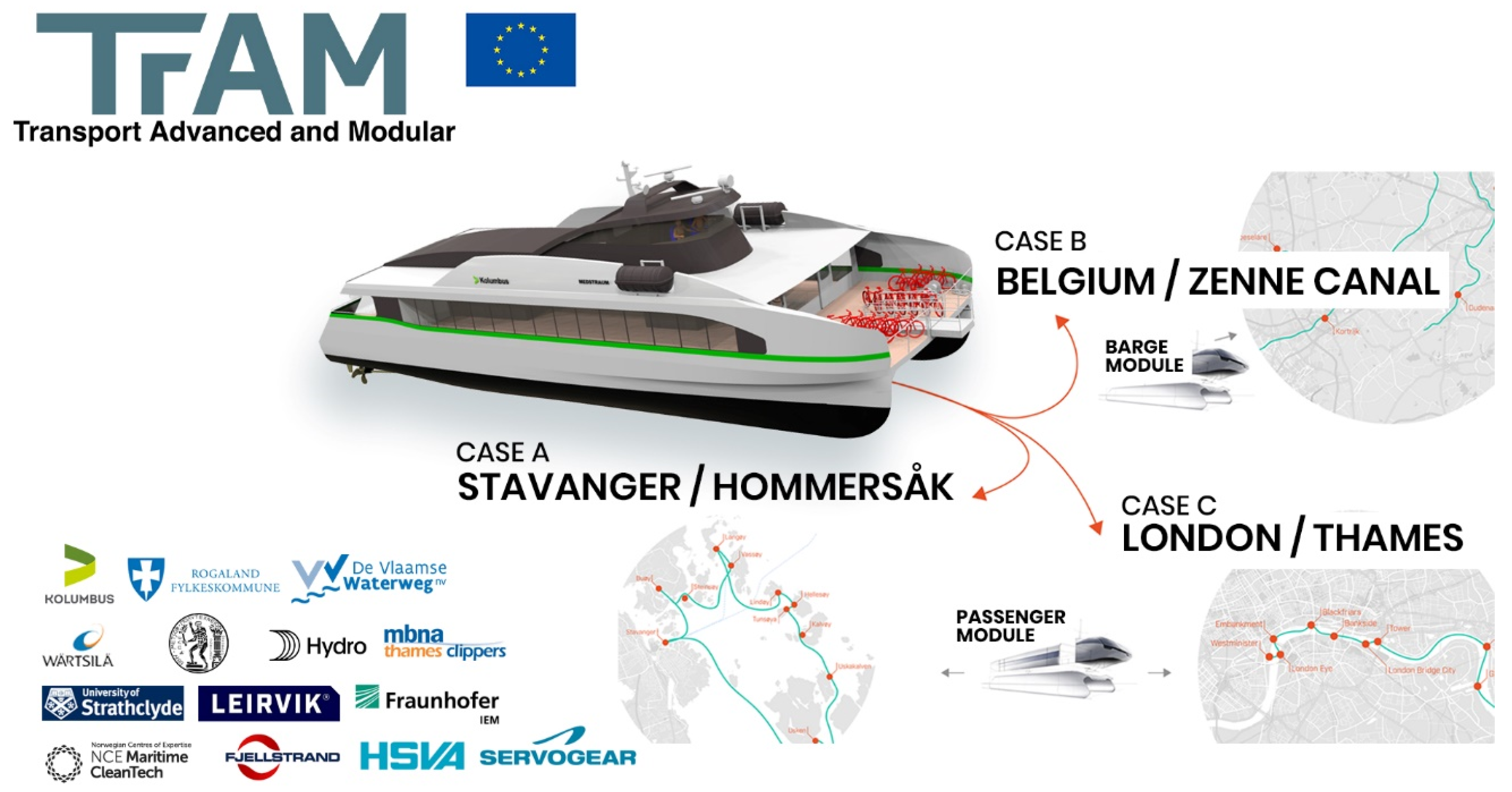
The project’s main objective is to develop and validate by the building and testing of a full-scale demonstrator a new concept for waterborne modular design and construction, with focus on an electrical/battery powered vessel for fast transport in protected waters, coastal areas and inland waterways. The project will result in a new battery driven, fast catamaran vessel with zero emissions that will operate between Stavanger and Hommersåk on the west coast of Norway (Figure 1). The uniqueness of the TrAM project is that it aims at the development of a fast catamaran vessel that will be the first one worldwide operating at high-speed while battery powered. In addition, new manufacturing/modular methods, known from the automotive and aircraft industry, will be implemented that are expected to contribute to significantly lower production and engineering costs. The construction of the demonstrator vessel by the well-established Norwegian shipyard Fjellstrand will be co-financed by Rogaland county (end-user). The project will also conduct two additional studies for the same type of vessel for shuttle operations on the Thames River in London and river cargo transports in Belgium to explore opportunities for similar zero-emission vessels on selected routes in Europe (and ultimately worldwide). The project is in the fore-front of recent developments by the maritime industry, namely in terms of the implemented zero-emission technology and manufacturing methods, but also because it enables electric-powered fast marine vehicles to be competitive in terms of offered services, comfort, life-cycle cost and the environmental footprint, when compared with conventional, diesel powered vessels.
The present review paper focuses on the design and technology issues related to the development of fast, zero-emission marine vehicles. After an introduction to the objectives of project TrAM, which is in the background of the presented study, the GHG emission problem of fast marine vehicles is addressed and even more of fast ships operating in urban areas, where the impact on the aerial environment and on public health is more severe than in the open sea. In Section 2, the encountered unique design and technology problems are briefly addressed, namely issues of marine batteries’ technical and economy characteristics, of specific requirements for the operation of battery ships as urban waterborne buses and of the technical limits for the achievable maximum speed by today’s battery characteristics; the latter is demonstrated by a comparative high-level design case study. In Section 3, the hydrodynamic optimization of fast catamaran vessels is addressed and an approach to a two-stage numerical optimization procedure is elaborated. The uniqueness of the hydrodynamic optimization problem of high-speed twin hull vessels is also addressed and the effect of design constraints discussed. Finally, Section 4, includes a summary of the main findings of this review and an outline of the way ahead for battery driven marine vehicles.
2. Unique Design and Technology Problems and Approach
The optimization of full-electric/battery-driven (zero-emission) ships in coastal (short distance) services introduces some new aspects in ship design optimization, when considering fast passenger vessels, noting that developments, until now, of full-electric/battery driven ships were limited to lower speed commuter services. However, with progress in battery technologies, the consideration of higher speeds seems feasible and will be demonstrated in the TrAM project [10]. The increase of the service speed introduces some unique design problems that need to be addressed for proving the feasibility of the concept.
These specific issues are:
- Technology issues:
- ○
- Low lightship weight, which is common to all high-speed craft. A major part of the lightship weight is the battery weight.
- ○
- Battery technology: battery capacity [kwh], battery weight and space requirements (gravimetric and volumetric energy density), charging frequency, battery life.
- ○
- Hull form optimization for minimum powering at specified service speed with multiple constraints for
- •
- Fitting of batteries in the hull or on deck
- •
- Fitting of e-propulsion motors in the hull
- •
- Fitting of a battery firefighting/safety system.
- ○
- Recharging technology (cold ironing/cable and/or inductive, contactless charging technologies).
- Operational issues:
- ○
- Time schedule and associated speeds for keeping a specified overall travelling plan, while calling at a number of closely located spots with specified arrival/departing time.
- ○
- Recharging frequency/recharging spots/recharging time.
We comment in the following Section 2 on the above unique issues to battery-driven, fast marine vehicles and passenger catamarans in particular, whereas their design and optimization are elaborated upon in Section 3.
2.1. Battery Technology
Developments in marine battery technologies were drastic in recent years. The present status and forecasts of the main characteristics of the most common type of marine batteries, namely of lithium-ion type, are shown below in Table 1 and Table 2, which have been compiled on the basis of recent data of the Technology Outlook 2050 report of Det Norske Veritas-Germanischer Lloyl (DNV-GL) [3].
The given emission reduction values in Table 1 are assumed for 100% of the battery power, when the batteries are charged from shore. However, the prime source of energy for the shore electricity grid needs to be also taken into account (see [11], for a lifecycle environmental assessment). In the TrAM project Stavanger study case, the electricity grid is more than 90% covered by renewable hydropower.
- 1)
- The cited uptake of ships with batteries is based on Maritime Battery Forum’s ship register/DNV-GL data [3]; according to data retrieved from [12] for year 2018, merely 0.15% of the entire world fleet (by number of ships) were on battery (fully electric or hybrid), but 3.07% were on order; These numbers are however rapidly growing in line with IMO’s ambitions for emission reductions by year 2050 (see IMO targets 2018 [1] and projections in [12]).
- 2)
- There are also other cell chemistries that are presently considered for marine use: proton-exchange membrane fuel cells (PEMFC); high-temperature PEMFC (HT-PEMFC); solid-oxide fuel cells (SOFC), all with hydrogen (H2) as prime fuel [13].
- 3)
- Acronyms used: CAPEX, capital expense; GHG, greenhouse gas; ton: 1000-kg mass; klt, 1000 litre; NOx, nitrogen oxides; OPEX, operational expense; SOx, sulfur oxides; W, watts; kWh, kilowatt hours.
Specific issues that are of particular interest in relation to the design of fast passenger vessels are:
- Battery capacity [kWh] in relation to battery weight and space requirement, particularly their specific gravimetric and volumetric energy density: For fast vessels, both these densities need to be as high as possible (light-weight, compact, high energy batteries); heavier and more voluminous batteries will increase the ship’s lightship weight, penalising the ship’s speed-power performance, and making the fitting in the slender hulls (even more so for twin hull vessels) difficult, if not impossible. Note that the comparable gravimetric energy density of diesel fuel is about 66 times higher (11,940 kWh/ton, vs. about 180 kWh/ton for the batteries, [14]). Considering a typical efficiency of diesel engines of about 40%, this ratio reduces to about 26, which is still substantial, when aiming at high capacities and low powering values for high speed vessels (discussion about the impact on ship design in Section 2.3).
- Battery life: with present technologies, battery life expectation is about 10 years, depending on the specific battery type, maintenance and recharging scheme; higher cost batteries are expected to serve longer, while towards the end of a battery’s life a decrease of the battery’s capacity should be expected. The recently launched EU funded HYDRA project aims at developing more sustainable, next-generation lithium-ion batteries [15]. A particular issue of interest is herein the possibility to replace parts of the fitted battery pack before the end of its life, as it can be also expected that in 10 years, battery energy densities will have significantly increased; this may lead even to an increase of the ship’s service speed (or of the ship’s operational range without recharging), assuming the availability of power by the fitted e-propulsion motors.
- Recharging technology: recharging hardware is being presently developed in parallel to battery technology; it may enable fast recharging, depending on the landside infrastructure and battery technology; recharging is mainly by cabling (cold ironing), but it may be also contactless/inductive at reduced recharging power/speed and stricter safety limitations [16].
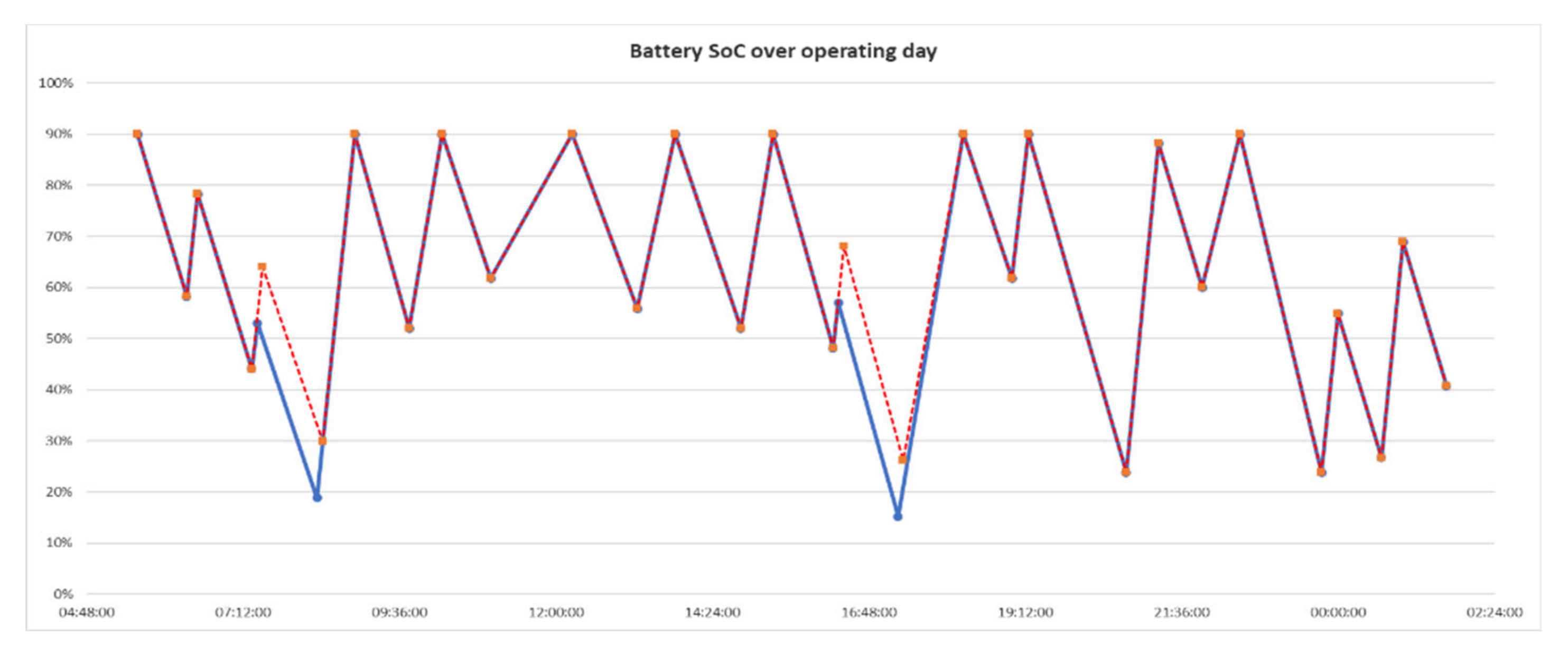
- Recharging sequence/State of Charge (SoC): the planning of the charging sequence in relation to the state of charge of the batteries is a most important issue affecting both ship design (through the capacity of the fitted batteries and their weight/space requirements) and the ship’s operation; it should be noted that according to class society’s provisions (e.g., DNV-GL [17]), the SoC should never go below 50%, even though this margin may be to a certain extent relaxed, if the ship is operating close to the shore. Extending the charging time or lowering the operational speed can improve the SoC timeline (see Figure 2).
- A trade-off between fitting higher capacity batteries or assuming more recharging spots must be made at an early design stage, as this determines the feasibility of the whole project. Note that the availability of recharging stations along the planned route is a complex issue to be resolved in collaboration with the public and land-based electrical grid authorities, while the investment for setting up a landside charging station is significant and can be only considered in the frame of wider planning of a city’s transportation infrastructure (see, e.g., Triangulum project on Smart City Integration [18]).
- Battery safety issues: a series of safety issues have surfaced in recent times in relation to the risk of fire and explosion in battery-driven vehicles (land- and waterborne vehicles). For marine applications important issues to be considered (beyond firefighting, isolation ventilation measures), which all significantly affect a ship’s design, as to the positioning of the battery racks, are [19]:
- ✓
- Off-gas ventilation and explosion risks
- ✓
- Fire suppression systems
- ✓
- Risk assessment and acceptance criteria
- ✓
- Emergency-escape routes from battery rooms and from ship
2.2. Operational Issues
Presently planned battery-driven, zero-emission ferries for coastal/river/inland water transport will be mostly operating as “Urban Water Shuttles”. They are expected to offer the same service in terms of journey plans (thus should have about the same speed and ticket price), as conventional ferries, but at increased comfort (low noise and vibrations) and negligibly low (if practically not zero) environmental impact. The integration of waterborne vessels and land-side interfaces, including terminals and smart-city infrastructure, ensuring comodality with other transport modes (buses, bikes, metro, etc.) and seamless integration with services (e-payment, traveler guides, etc.), is part of the TrAM [10] and of other EU funded projects (e.g., Triangulum [18]).
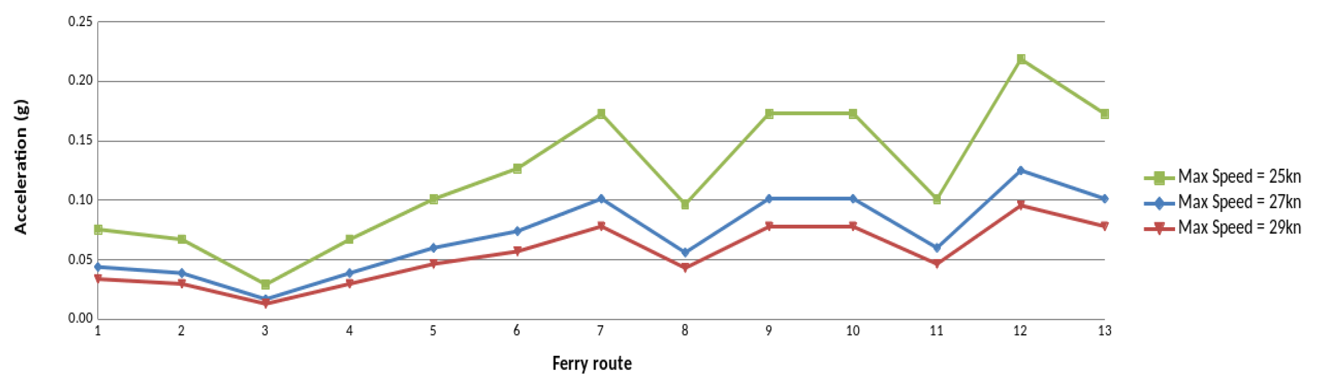
For keeping a fixed (already established) time schedule the battery driven vessel will be operating with varying speeds, reaching and keeping the maximum operational speed for a short time, while accelerating and decelerating most of the time. Depending on the maximum achievable operational speed and for keeping a fixed time schedule, the times for acceleration and deceleration will vary, with an immediate effect on the magnitude of the required acceleration/deceleration (Figure 3). The following diagrams show for a hypothetical operational scenario of the Stavanger demonstrator at varying maximum speeds, the timeline of speed and of associated accelerations, which are partly very high (Figure 4).
An operational scenario like the above has an immediate impact on ship design by way of the specification of the required maximum operational speed in relation to the transport capacity that determines the size of the ship and its displacement. The maximum operational speed is determined in relation to the achievable accelerations by the employed propulsion system. The max speed and acceleration will jointly lead to the estimation of the magnitude of the required propulsion power [kW], to be covered by the fitted battery capacity, and the associated propulsive performance.
For the estimation of the required thrust to overcome the increased unsteady resistance during acceleration and to achieve a certain speed within a certain time (accelerated forward motion), the unsteady forward ship motion needs to be simulated. It is clear that accelerating the vessel to a certain speed it will need an increased thrust (and machinery torque), depending on the magnitude of the required acceleration. This increase in resistance, compared to the steady motion, is directly proportional to the ship’s added mass in the longitudinal direction, which can be roughly estimated by an extension of Lagally’s theorem as presented by Landweber and Yih [21]. For a precise estimation, direct URANS unsteady flow calculations by use of the FreSCo+ code of HSVA can be performed [22].
The required battery capacity [kWh] and propulsion power [kW] will be determined by taking into account the power requirements for the specified journey and the time until the next battery recharging. Note that the life of batteries strongly depends on the frequency of recharging and the loading level (state of charge) of the batteries: clearly batteries of larger capacity with less % consumption of energy when charged, will have a longer lifetime than smaller ones. However, as the battery capacity is directly related to the batteries’ weight and space requirements, this has an immediate effect on ship’s design, sizing and displacement and thus also on the installed power and maximum speed. These contradicting requirements call for an iterative design procedure, where the fulfilment of the set constraints is traditionally achieved by a trial and error procedure after some loops of the design spiral [23]. Modern, holistic approaches to ship design are rather based on synthetic, parallel running design approaches and the use of mathematical multiobjective design optimization procedures with multiple constraints, as shown in project HOLISHIP [24,25]. As far as the hydrodynamic optimization is concerned, similar approaches are elaborated in Section 3.
Assuming now a maximum required speed, minimum required acceleration and the battery capacity (mostly) specified by the operator (in line with its planned speed profile/time schedule and recharging plan), the hydrodynamic optimization of the ship’s hull and propulsion system needs to address and determine in parallel three issues (objectives):
- 1)
- The required average and maximum speed to meet the schedule including intermediate stops and recharging.
- 2)
- The minimum required propulsion power for the vessel to achieve the required maximum speed.
- 3)
- The minimum required propulsion power, torque moment and thrust to achieve the required minimum acceleration.
Objective 1 may be optimized independently for alternative routes, number of stops and recharging schedules (in terms of time sequence and location). Objective 2 corresponds to the classical “speed−resistance−propulsion’’ power optimization problem in naval architecture and a minimization of the power will lead to smaller batteries or to less frequent recharging calls. Objective 3 is related to the operational profile laid down in objective 1; it may be considered as an additional constraint to objective 2, or may be optimized in parallel if a proper modelling of the unsteady forward speed problem is available.
2.3. Limits on the Achievable Maximum Speed of Battery-driven Marine Vehicles—Case Study
The optimization of a ship’s hull form for low resistance and powering, next to lightweight construction and outfitting, is imperative in the design of high-speed marine vehicles. The question on the limits of the achievable service speed and operational range for battery-driven ships without recharging (for conventional ships: hours of operation without refueling) is elaborated below on the basis of a comparative case study referring to a high-level comparison of the main technical data of two fast catamarans of about 30 m in length and with about the same passenger capacity.
For the conventional, diesel-driven catamaran, we take as reference a built ship with published technical data, namely the Red Jet 3 [26] operating between Southampton and the Isle of Wight with a service speed of 35 knots. This catamaran was the subject of hydrodynamic optimization by NTUA in the frame of the EU funded project FLOWMART (2000–2003), see [27,28]. We compared this conventional high-speed catamaran ship, having a length of 32 m and a displacement of about 90 tons, with a battery-driven catamaran of 30 m length and slightly lower displacement, operating with 23 knots service speed. The available energy capacity of the 32 m conventional catamaran, with an installed power of 3000 kW, is estimated to be 12,240 kWh for 4.5 h operation at 35 knots speed, assuming operation at 85% of MCR. For the battery-driven, slightly smaller catamaran, we assumed the fitting of batteries of 1300 kWh capacity and 1100 kW e-motors for about 2 h operation at 23 knots speed (ratio in energy capacities about 10:1). In this comparative exercise, we take into account the installed power, weight and space requirements for the main machinery of the conventional catamaran (2 MTU 12V396 TE94 engines with reduction gears), including the amount of its fuel and lubrication oil bunkering, totaling 15.4 tons, and the comparable weight and space requirements of the battery-driven ship (15 ton battery pack for 1300 kWh and 2 tons for the 2 × 550kW e-motors. This means that the conventional catamaran has a range of more than twice the range of the battery driven catamaran, while operating with a 50% higher speed. From this high-level comparison, it becomes evident that battery-driven catamarans with present and foreseeable battery technology cannot achieve the comparably very high-speeds of conventional catamarans due to the inherent low gravimetric energy density of present batteries, compared to the diesel fuel/motors option (see comments on battery capacity in Table 1). Of course, the GHG emissions of the all-electric catamaran are practically reduced to zero (assuming green electric prime energy generation), as are the noise and vibration levels.
Closing this section, it should be noted that marine battery technology is rapidly improving towards the development of more compact/lighter, higher capacity, higher gravimetric/volumetric energy efficiency and longer life products. In this respect, developments in fuel cells technology look even more promising. Finally, the implementation of an energy management system is imperative for battery driven vehicles. Similar systems are widely employed by the automotive industry in fully electrical or hybrid cars and are driving developments in the maritime industry now and in the years to come.
3. Hydrodynamic Optimization
The hydrodynamic optimization of twin-hull vessels is a multiparametric mathematical and engineering problem with multiple objectives and constraints. We restrict herein our optimization problem to the design of small passenger catamarans and assume the specification of a certain payload capacity (for passengers and light cargo) and service speed by the end user. It is the designer’s task to find the vessel’s optimal dimensions (length, overall beam, demihulls’ beam and separation distance), hull form and displacement, the latter in dependence on the ship’s lightship weight (weight of structure, machinery and outfitting). The optimization refers in general to the ship’s calm water performance, thus to a minimization of the ship’s resistance and of required power, by maximization of the propulsive efficiency [29]. For a battery-driven, fast catamaran the hydrodynamic optimization appears even more urgent, than for a conventional high-speed craft, because the weight and space constraints imposed by the fitting of the battery racks for the required battery capacity and the fitting of e-motors driving the propellers more significantly affect the ship’s design and the associated displacement-speed-power profile.
In view of the many unknown parameters involved in the set optimization problem, which make an exhaustive exploration of the design space practically impossible, it is advisable to reduce the number of unknown parameters to the feasible, without compromising in the search for the optimal solution. This parameter reduction process is based on the designer’s experience and on background fundamental studies on the effect of certain design parameters on ship’s properties (herein mainly on ship’s weight and displacement) and on hydrodynamic performance (here total calm water resistance and its components). An increase of the demihull’s length (slenderer demihulls for a given displacement) generally leads to an increased wetted surface and of frictional resistance, while the decrease of wave resistance is modest at higher speeds, for high Froude numbers (Froude number: dimensionless speed ratio V/(g L)1/2 ) over about 0.60 [23]. An increase of the demihulls’ separation distance leads to a reduction of the interaction effect increasing the ship’s wave resistance at medium Froude numbers below about 0.60, but at the expense of a higher structural weight for the strength of the deck support structure, which leads to an increased displacement and to losses of the achieved gains in the wave resistance account. An asymmetry of the demihulls may be beneficial for wave resistance, but gains depend on the operational Froude number. An optimization of the lengthwise displacement distribution may lead to favorable (negative) demihull interaction effect, as shown in [30].
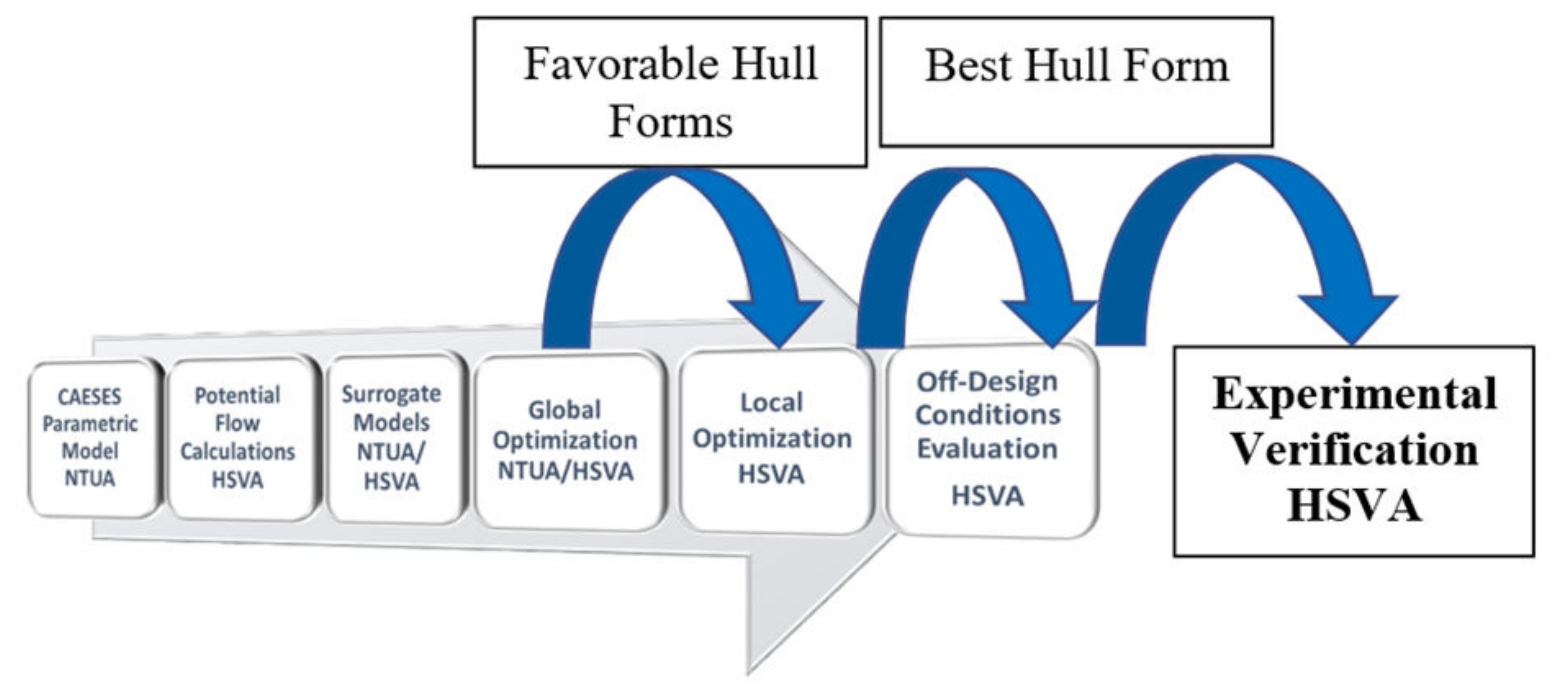
Based on this reasoning, it proves very efficient in practice to proceed with a two-stage optimization procedure, namely first a global one referring to the determination of the ship’s main dimensions and its integrated hull form characteristics, followed by a local one referring to details of the ship’s hull form and its propulsion system. Note that the terms global and local optimization are often used differently in optimization theory, namely with respect to the identification of global and local optima in optimization problems involving rapidly changing objective function(s), which is herein not the case. This optimization procedure relies on the development of a parametric model for the variation of the geometry of the ship’s hull form that can be readily accomplished by use of the software platform CAESES [31]. The multiple steps on this pathway to the selection of the final best hull form are outlined in Figure 5.
The parametric model of the hull form for the TrAM project Stavanger demonstrator was developed on the CAESES platform of Friendship Systems on the basis of 20 design parameters [32]. It offers the possibility to automatically generate smooth hull forms in the specified range of the main particulars of the demihulls along with the possibility to control and modify a series of important hull form details. A large number of about 1000 alternative hull forms was generated on the basis of four main design parameters (waterline length, demihull beam, draft and transom stern width) and assessed with the potential theory 3D panel code v-SHALLO of HSVA [33] to form the basis for the development of surrogate models (response surfaces) for the estimation of calm water resistance. Global optimization studies were carried out using the NSGA-II genetic algorithm, and two of the most promising designs were selected for more refined local optimization [32]. These hull forms were further optimized using 10 parameters of the CAESES parametric model referring to definition of the tunneled transom stern area and the propeller diameter, its position and inclination. Eight constraints referring to the inclination and fitting of the propeller shaft, as well as to propeller clearances from the hull for low vibrations were considered. Optimization runs were with HSVA’ s URANS tool FreSCo+, while focusing on the optimization of the propulsive efficiency by carefully analyzing the performance of the unique tunneled transom stern and its interaction with the fitted propellers (two CP propellers), propeller shaft, brackets and rudder (two twisted rudders). Details of the hydrodynamic optimization of the Stavanger demonstrator were elaborated in a recent paper of Papanikolaou et al. [34] and details can be omitted herein. It is, however, important to review some significant results of this research.
Numerical predictions for the resistance and the required power in the model and full-scale of the numerically optimized catamaran hull form for the specified operational profile were verified by physical tests with a 1:5.6 scaled catamaran model (5.34 m long) at the large towing tank of HSVA. The most striking result of these tests is the verification of the propulsive efficiency of the finally selected hull form, which achieved very high values of 78.2% at the design speed of 23 knots and even 80% at 27 knots (see Table 3).
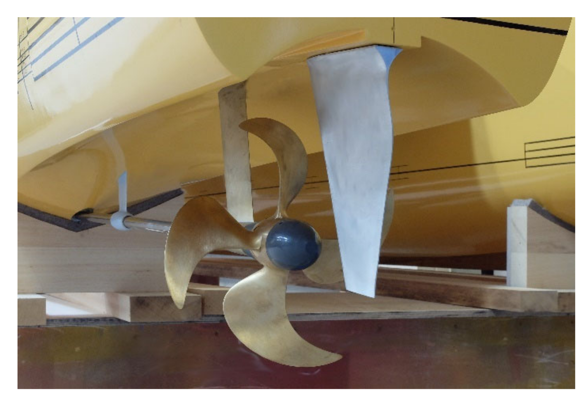
This remarkable and unique result deserves some brief commentary. As shown in Table 3, the tested hull had very low thrust deduction and wake fractions, high open water propeller efficiency (about 78% for over 21 knots speed) and even higher total propulsive efficiency (relative rotative efficiency over 100%). This means that the unique tunneled and longitudinally cumbered transom stern arrangement effectively reduced the required thrust and delivered propeller power at higher speeds, compared to the performance of a conventional catamaran’s stern (Figure 6). Note, also, that the wake fraction for Froude number around 0.50 (17 to 21 knots), corresponding to the “last hump” of wave resistance, was here practically zero, which effectively means that the frictional part of the wake was outweighed by the pressure part due to the generated unique transom-stern flow.
The Stavanger catamaran’s hull form was twice model-tested at HSVA’ s towing tank, firstly in December 2019 for the optimized design alternative with the battery racks in the demihulls and secondly in May 2020 with a design alternative, in which the battery racks were placed on the deck area. This last design option proved better than the first one, as could be expected and numerically predicted, due to the relaxed constraints on the demihull’s minimum width (see Figure 7, the verification of the numerical prediction for the power requirement of the two design alternatives under delivery/trial conditions). These results form the basis for the final selection of the hull form, propulsive arrangements, battery capacity and electric motor power by the yard (and operator) for the desired speed profile of the Stavanger demonstrator.
Specific Optimization Issues of Fast Catamarans
When designing a conventional, diesel-driven fast catamaran (or twin hulled vessel in general) the design option to place the main machinery in the demihulls is the most common one, assuming the availability of sufficient space and especially of sufficient demihull beam and all-around clearance for the engines. Thus, in the parametric optimization of the demihulls, a minimum demihull beam requirement over a certain hull region lengthwise (engine room) needs to be considered as constraint. Likewise for a battery driven catamaran, a minimum demihull beam requirement may be considered when the battery racks are placed in the demihulls, even though the option to place the batteries on deck is less cumbersome in terms of safety and less stringent for the hull optimization. An interesting question occurs in the hydrodynamic optimization, namely whether, for fixed demihull separation distance, the demihulls with the minimum beam are the best ones. This apparently trivial question has a more complex answer, while noting that the demihull separation distance may also be subject of optimization, even though it is often fixed as a design constraint, because of a specific deck arrangement determined by the operator and the yard)).
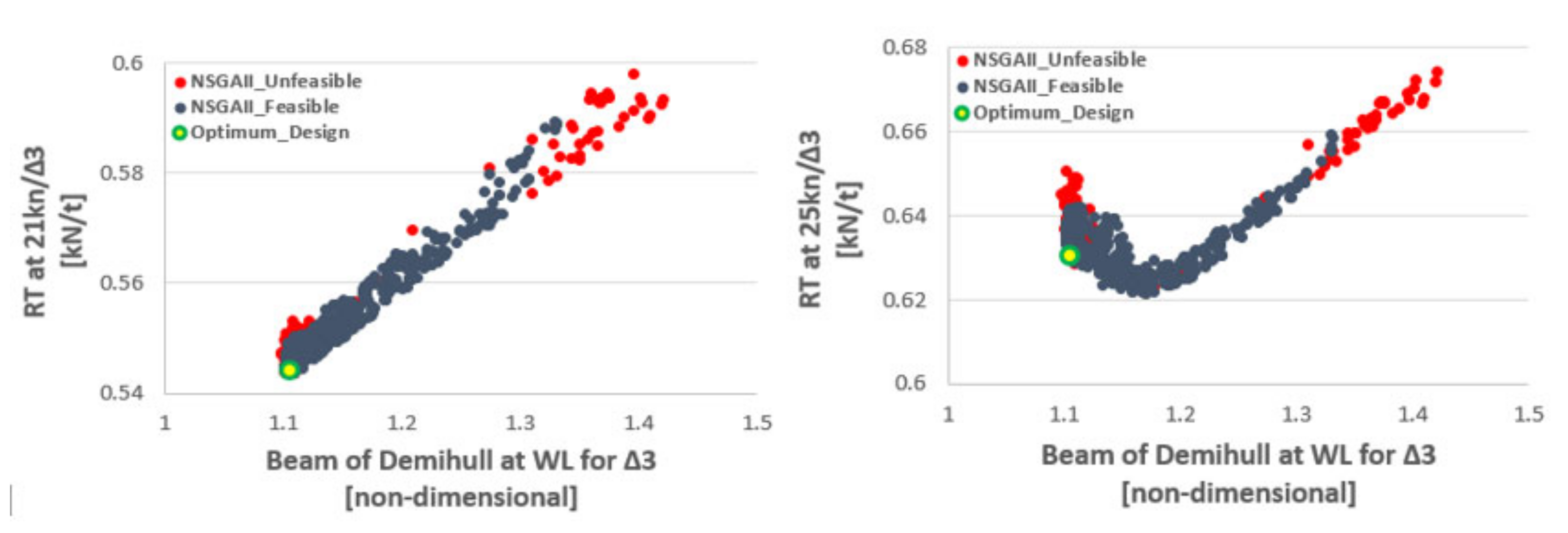
Below in Figure 8, we can see some typical results for the calm water resistance per ton of displacement for a set of 850 parametrically generated catamaran variants against the non-dimensional beam at WL for 21kn (left) and 25 kn (right) speed.
The optimum design for the 23 knots speed is marked in the figures with a green circle. However, a clear differentiation between the optimization for 21 kn and 25 kn can be observed in the graphs: whereas the demihull beam of the optimum hull form for 21kn has the set minimum beam value of the demihull, this is not so when optimizing for 25 kn service speed. The reason for this, at first sight, unexpected behavior is elaborated below.
When the planned ship is operating beyond the last hump of wave resistance, the Froude number > 0.50 (in fact the speed of 21 knots for a 30 m catamaran corresponds to Froude 0.63 and 25 knots to Froude 0.75), the wave resistance part of the total resistance reduces rapidly to even less than 40% of the total resistance, whereas the % of the friction/viscous resistance part, which is dependent on the hull’s wetted surface, steadily increases. For a given displacement and length, a reduction of the demihull’ s beam and an increase of the draft generally leads to hull forms with increased wetted surface; thus, it may be expected that at higher speeds, optimal hull forms with respect to total resistance will be associated with wider demihulls, not at the set lower limits for the beam.
To demonstrate this, an additional design exploration and optimization study was conducted for the same 30 m catamaran optimized for 23 knots speed (Froude 0.69). In Figure 9, the wetted surface of parametrically generated 850 designs for a 30 m catamaran with fixed displacement and demihull length WL, but without/or much lower demihull beam constraint, as ratio to a demihull’s wetted surface (hull06), for which the beam was constrained to a low limit. It is evident that all generated designs proved to have a larger wetted surface of up to about 6.5%, when setting the low limit of the beam at 0.80. This could be expected as it is well established that for 3D solids of given volume, the sphere has the smallest wetted surface.
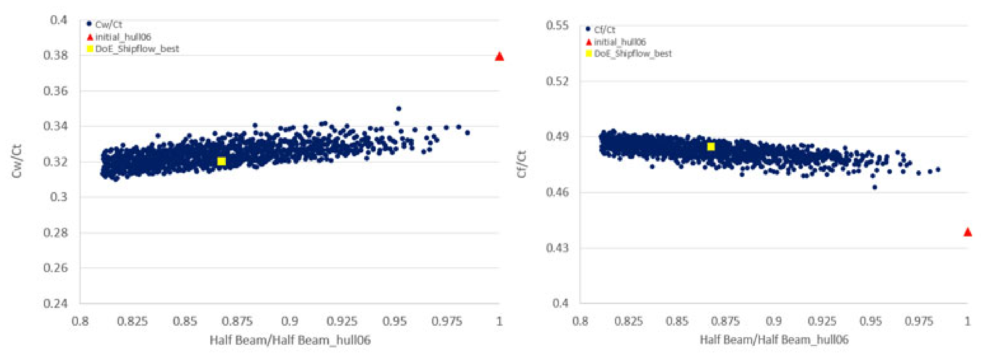
Based on this finding, it is not surprising that the reduction of the catamaran’s total resistance through a decrease of the demihulls’ beam is limited, namely determined by the reduction in wave resistance, while the frictional resistance increases (Figure 10).
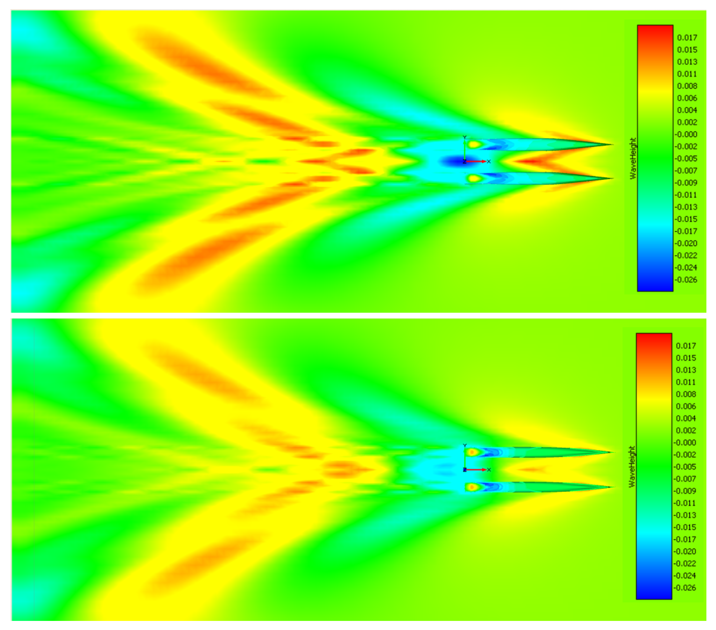
The overall outcome for the total resistance depends on the ship’s operating Froude number and the percentage value of the wave and friction to the total resistance. In Figure 11 the calculated wave patterns for the optimized hulls with (up) and without (down) demihull beam constraint are shown, in which the reduced wave resistance for the hull down is visible.
As could be expected, the demihull design with the relaxed demihull beam constraint, corresponding herein to a catamaran design with the battery-racks placed on deck, proves hydrodynamically superior, which is also beneficial from the point of view of safety against the risk of battery fire and explosion hazards.
4. Summary and Conclusions
The paper dealt with a critical review of the unique problems related to the technology, design and operation of zero-emission, battery driven, fast catamaran vessels. These unique problems refer to the batteries’ present technology and their low gravimetric and volumetric energy densities, whereas the rapidly changing battery and associated equipment technology looks promising. The characteristics of marine batteries and of associated equipment (e-motors) and their impact on the design of fast catamaran vessels were reviewed. It proves that battery-driven catamarans may achieve appreciably high speeds, but there are limits to this which are set by the relatively low energy densities of present marine batteries. For small passenger ships, that are nowadays planned to operate as zero-emission, fast vehicles in coastal/river/inland water transport services as “urban water shuttles”, the hydrodynamic optimization is imperative and determines the feasibility of the concept.
The paper reviewed the hydrodynamic optimization of fast catamarans, addressing specific problems caused by design constraints affecting their dimensioning and hull form design. This review includes a critical commentary of the outcome of the hydrodynamic optimization of a 30 m LWL, 23 knots service speed catamaran vessel that is presently being investigated in the frame of the EU funded project TrAM (Transport: Advanced and Modular, https://tramproject.eu/) and will lead to the development and construction of a physical demonstrator for operation in the Stavanger area in Norway. The associated multiobjective, parametric hydrodynamic optimization referred to the fitting of the least battery capacity and minimum powering of e-motors to achieve operational requirements, while complying with set design and regulatory constraints. The obtained results proved the feasibility of the TrAM zero-emission, fast catamaran concept and will decisively support the final design of the Stavanger demonstrator, planned to enter service in the Stavanger area before the end of the TrAM project in the first half of 2022.
All in all, the critical issues and challenges related to the use of batteries as energy source for the propulsion of small, fast vessels in urban waterborne transport appear tractable, even if the building of prototypes is inherently associated with a series of smaller technical problems. The building costs will be generally higher than that of comparable conventional vessels, but their life-cycle cost assessment looks promising and greatly dependent on the cost of charged electricity kWh. Thus, it may be expected that the way ahead in coastal/urban waterborne transport will be through the use of battery driven vehicles and shipbuilders of small to medium marine craft will need to be prepared for it. Finally, the building of proper landside infrastructure (charging stations and connection to the landside electric grid) and the planning of multimodal transportation networks will be a prime issue for local governments and transport operators to take care of in the years to come.
Funding
This research has received funding by the EU H2020 Research Project TrAM, Grant Agreement No 769303.
Acknowledgments
The author is thankful to Aphrodite Kanellopoulou, George Zaraphonitis, Aimilia Alissafaki (NTUA), Yan Xing-Kaeding and Johannes Strobel (HSVA), Mikal Dahle (Kolumbus), Georg Andal (Servogear) and Edmund Tolo (Fjellstrand Shipyard) for their contributions to the presented work. The TrAM project has received funding from the European Union’s Horizon 2020 research and innovation programme under grant agreement No 769303.
Conflicts of Interest
The author declares no conflict of interest.
References
- International Maritime Organisation (IMO). Adoption of the Initial IMO Strategy on Reduction of GHG Emission from Ships and Existing IMO Activity Related to Reducing GHG Emissions in the Shipping Sector; Note by the International Maritime Organization to the UNFCCC Talanoa Dialogue; International Maritime Organisation: London, UK, 2018. [Google Scholar]
- Serra, P.; Fancello, G. Towards the IMO’s GHG Goals: A Critical Overview of the Perspectives and Challenges of the Main Options for Decarbonizing International Shipping. Sustainability 2020, 12, 3220. [Google Scholar] [CrossRef] [Green Version]
- DNV-GL. Maritime Forecast to 2050—Energy Transition Outlook; DNV-GL: Oslo, Norway, 2019. [Google Scholar]
- European Commission. Long Term Climate Strategy and Targets. Available online: https://ec.europa.eu/clima/policies/strategies/2050_en (accessed on 8 November 2020).
- European Commission. Maritime Transport Policy. Available online: https://ec.europa.eu/transport/modes/maritime_en (accessed on 8 November 2020).
- European Commission. Sustainable Transport. Available online: https://ec.europa.eu/transport/themes/sustainable_en (accessed on 8 November 2020).
- Dahl, M. Development of the World’s First Zero Emission Fast Ferry. SNAME Webinar. Available online: www.sname.org (accessed on 22 October 2020).
- Kollektivtraffikk-Foreningen: Association of Public Transport Companies in Norway. Available online: https://kollektivtrafikk.no/markedsoversikt-sjo/ (accessed on 8 November 2020).
- E-Ferry Project. Available online: http://e-ferryproject.eu/ (accessed on 8 November 2020).
- TrAM, Transport: Advanced and Modular, EU H2020 Research Project, Grant AGREEMENT No 769303, (2018–2022). Available online: https://tramproject.eu/ (accessed on 8 November 2020).
- Jeong, B.; Jeon, H.; Kim, S.; Kim, J.; Zhou, P. Evaluation of the Lifecycle Environmental Benefits of Full Battery Powered Ships: Comparative Analysis of Marine Diesel and Electricity. J. Mar. Sci. Eng. 2020, 8, 580. [Google Scholar] [CrossRef]
- DNV-GL. Maritime Forecast to 2050—Energy Transition Outlook; DNV-GL: Oslo, Norway, 2020. [Google Scholar]
- DNV GL’s Alternative Fuels Insight (AFI) Portal. Available online: https://www.dnvgl.com/services/alternative-fuels-insight-128171 (accessed on 8 November 2020).
- Global Fuel Economy Initiative for Zero Carbon Vehicles by 2050. Available online: https://www.globalfueleconomy.org (accessed on 8 November 2020).
- HYDRA Project. Available online: https://corvusenergy.com/corvus-energy-to-be-part-of-eu-hydra-research-project-to-develop-more-sustainable-next-generation-lithium-ion-batteries/ (accessed on 8 November 2020).
- Wärtsilä Wireless Charging. Available online: https://www.wartsila.com/marine/build/power-systems/shore-connections/wireless-charging (accessed on 8 November 2020).
- DNV-GL; EMSA. Maritime Battery Study, Electrical Energy Storage for Ships; rep. no. 2019-0217, rev.3; EMSA (European Maritime Safety Agency): Lisbon, Portugal, 2019. [Google Scholar]
- Triangulum: Smart City Integration Project of Manchester, Eindhoven and Stavanger, European Commission Funded Project. Available online: https://www.triangulum-project.eu (accessed on 8 November 2020).
- DNV-GL. Technical Reference for Lithium-Ion Explosion Risk and Fore Suppression; Report No. 2019-1025, rev. 4; EMSA (European Maritime Safety Agency): Lisbon, Portugal, 2019. [Google Scholar]
- Papanikolaou, A.; Xing-Kaeding, Y. Some Unique Questions, when Optimising Battery-driven High-speed Marine Vehicles, HSVA NewsWave. In The Hamburg Ship Model Basin Newsletter; HSVA: Hamburg, Germany, 2019. [Google Scholar]
- Landweber, L.; Yih, C.S. Forces, Moments and Added Masses for Rankine Bodies. J. Fluid Mech. 1956, 1, 319–336. [Google Scholar] [CrossRef]
- Hafermann, D. New RANSE Code FreSCo for Ship Application. In Proceedings of the Jahrbuch der Schiffbautechnischen Gesellschaft (STG), Hamburg, Germany, 9 October 2007; Volume 101. [Google Scholar]
- Papanikolaou, A. Ship Design- Methodologies of Preliminary Design; Springer: Berlin/Heidelberg, Germany, 2014; p. 628. ISBN 978-94-017-8751-2. [Google Scholar]
- HOLISHIP (2016–2020). Holistic Optimisation of Ship Design and Operation for Life Cycle, Project Funded by the European Commission, H2020- DG Research, Grant Agreement 689074. Available online: http://www.holiship.eu (accessed on 8 November 2020).
- Papanikolaou, A.; Boden, B.; Harries, S.; Hooijmans, P.; Marzi, J.; Le Nena, R.; Torben, S.; Yrjänäinen, A. Holistic Approach to Ship Design: Tools and Applications. J. Ship Res. 2021. (publication, to appear). [Google Scholar]
- Red Jet3. Technical Information about Red Jet3 Catamaran of Red Funnel Co. 2020. Available online: https://www.redfunnel.co.uk/en/isle-of-wight-ferry/fleet-information/hi-speed/red-jet-3/ (accessed on 8 November 2020).
- FLOWMART. Fast Low Wash Maritime Transportation, Project funded by the European Commission FP4; Contract Number G3RD-CT 1999-00013; European Commission: Brussels, Belgium, 2000. [Google Scholar]
- Zaraphonitis, G.; Papanikolaou, A.; Mourkoyiannis, D. Hull Form Optimization of High-Speed Vessels with Respect to wash and Powering. In Proceedings of the 8th International Marine Design Conference, IMDC’03, Athens, Greece, 5–8 May 2003. [Google Scholar]
- Skoupas, S.; Zaraphonitis, G.; Papanikolaou, A. Parametric Design and Optimisation of High-Speed Ro-Ro Passenger Ships. J. Ocean Eng. 2019, 189. [Google Scholar] [CrossRef]
- Papanikolaou, Α.; Kaklis, Ρ.; Koskinas, C.; Spanos, D. Hydrodynamic Optimization of Fast Displacement Catamarans. In Proceedings of the 21st Symposium on Naval Hydrodynamics (ONR), Trondheim, Norway, 24–28 June 1996. [Google Scholar]
- Harries, S.; Abt, C. CAESES®—The HOLISHIP Platform for Process Integration and Design Optimization. In A Holistic Approach to Ship Design; Papanikolaou, A., Ed.; Optimisation of Ship Design and Operation for Life Cycle, Springer: Berlin/Heidelberg, Germany, 2019; Volume 1, ISBN 978-3-030-02809-1. [Google Scholar]
- Kanellopoulou, A.; Xing-Kaeding, Y.; Papanikolaou, A.; Zaraphonitis, G. Parametric Design and Hydrodynamic Optimization of a Battery-Driven Fast Catamaran Vessel. In Proceedings of the Conference on Sustainable and Safe Passenger Ships, Royal Institute of Naval Architects (RINA) and Hellenic Institute of Marine Technology (HIMT), Athens, Greece, 4 March 2020. [Google Scholar]
- Gatchell, S.; Hafermann, D.; Jensen, G.; Marzi, J.; Vogt, M. Wave Resistance Computations—A Comparison of Different Approaches. In Proceedings of the 23rd Symposium on Naval Hydrodynamics, Val de Reuil, France, 23 October 2020. [Google Scholar]
- Papanikolaou, A.; Xing-Kaeding, Y.; Strobel, H.; Kanellopoulou, A.; Zaraphonitis, G.; Tolo, E. Numerical and Experimental Optimization Study on a Fast, Zero Emission Catamaran. J. Mar. Sci. Eng. 2020, 8, 657. [Google Scholar] [CrossRef]
Figure 1.
Image of the Stavanger Demonstrator and planned TrAM project replication studies for zero-emission, urban waterborne transport [10] https://tramproject.eu/.
Figure 1.
Image of the Stavanger Demonstrator and planned TrAM project replication studies for zero-emission, urban waterborne transport [10] https://tramproject.eu/.

Figure 2.
Simulated battery SoC for the Stavanger demonstrator and the effect of extending the charging time by 5 min (dotted line) [7].
Figure 2.
Simulated battery SoC for the Stavanger demonstrator and the effect of extending the charging time by 5 min (dotted line) [7].

Figure 3.
Typical operational speed profile for a prespecified number of port calls and travel plan [20].
Figure 3.
Typical operational speed profile for a prespecified number of port calls and travel plan [20].

Figure 4.
Required acceleration profile for different maximum speeds and prespecified travel plan [20].
Figure 4.
Required acceleration profile for different maximum speeds and prespecified travel plan [20].

Figure 5.
Multistage numerical optimization and experimental verification.

Figure 6.
Close-up of the transom stern area of the tested Stavanger model, with fitted propellers, shafts, brackets and rudders [34].
Figure 6.
Close-up of the transom stern area of the tested Stavanger model, with fitted propellers, shafts, brackets and rudders [34].

Figure 7.
Prediction of rated delivered horsepower under trial conditions for the Stavanger demonstrator on the basis of model experiments and CFD calculations by HSVA (originally optimized tested in December 2019 and revised hull form tested in May 2020).
Figure 7.
Prediction of rated delivered horsepower under trial conditions for the Stavanger demonstrator on the basis of model experiments and CFD calculations by HSVA (originally optimized tested in December 2019 and revised hull form tested in May 2020).

Figure 8.
Typical calm water resistance per ton of displacement against non-dimensional beam at WL for 21kn (left) and 25 kn (right) [32].
Figure 8.
Typical calm water resistance per ton of displacement against non-dimensional beam at WL for 21kn (left) and 25 kn (right) [32].

Figure 9.
Wetted surface of parametrically generated 850 designs for a 30 m catamaran with fixed displacement and demihull length WL as ratio to demihull’s beam constraint; square symbol: best for beam constraint at 0.8, triangle symbol: best with beam constraint at 1.0.
Figure 9.
Wetted surface of parametrically generated 850 designs for a 30 m catamaran with fixed displacement and demihull length WL as ratio to demihull’s beam constraint; square symbol: best for beam constraint at 0.8, triangle symbol: best with beam constraint at 1.0.

Figure 10.
Percentage of wave CW (up) and frictional Cf (down) to total Ct resistance coefficient for 30 m catamaran at 23 knots (850 parametrically generated designs, square symbol: best without beam constraint, triangle symbol: best with beam constraint).
Figure 10.
Percentage of wave CW (up) and frictional Cf (down) to total Ct resistance coefficient for 30 m catamaran at 23 knots (850 parametrically generated designs, square symbol: best without beam constraint, triangle symbol: best with beam constraint).

Figure 11.
Wave patterns of optimized 30 m catamarans with demihull beam constraint (up) and demihull beam relaxed (down).
Figure 11.
Wave patterns of optimized 30 m catamarans with demihull beam constraint (up) and demihull beam relaxed (down).


Table 1.
Main Technical Characteristics of Lithium-Ion Marine Batteries [3].
Table 1.
Main Technical Characteristics of Lithium-Ion Marine Batteries [3].
| Properties | NMC (Nickel Manganese Cobalt Oxide) | LPF (Lithium Iron Phosphate) | LTO (Lithium Titanate Oxide) | |
|---|---|---|---|---|
| Technical Characteristics | Typical application | Short-sea (all-electric) to deep-sea (hybrid) | ||
| Specific power [kW/ton] | 450–660 | 1000 | 3000–5100 | |
| Specific energy density (Gravimetric) [kWh/ton] | 150–220 | 90–120 | 50–80 | |
| Specific energy density (Volumetric) [kWh/klt] | 350–580 | 300–350 | 110–140 | |
| Thermal stability | Medium | Medium | High | |
| Flammability | High | Medium | Medium | |
| Toxicity | High | High | High | |
| Efficiency | 85–95% | |||
| Main characteristics | Low specific power, but high specific energy; medium thermal stability (lifespan); lower initial cost/kWh | Medium specific power and specific energy; medium thermal stability (lifespan); lower initial cost/kWh | High specific power, but lower specific energy; higher thermal stability (lifespan); higher initial cost/kWh | |
| Potential reduction in emissions to air (GHG, SOx, NOx, PM) | 100% | |||
Table 2.
Main Economic Characteristics of Lithium-Ion Marine Batteries [3].
Table 2.
Main Economic Characteristics of Lithium-Ion Marine Batteries [3].
| Specific Data | NMC (Nickel Manganese Cobalt Oxide) | LPF (Lithium Iron Phosphate) | LTO (Lithium Titanate Oxide) | |
|---|---|---|---|---|
| Typical CAPEX [per kWh in USD] | 500–1000 | 1000–2000 | ||
| OPEX | Determined by electricity price | |||
| Flexibility | Feasible for hybrid config. and small all-electric ships | |||
| Current uptake (2019) | Battery ships in operation | 93 | 21 | 1 |
| Battery ships on order | 79 | 9 | 7 | |
Table 3.
Experimentally measured hull and propulsive efficiencies for the design displacement of the Stavanger demonstrator (full scale). V: speed in knots; Fn: Froude number; t: thrust deduction fraction; w: Taylor wake fraction; ETAH: hull efficiency; ETAO: open water propeller efficiency; ETAR: relative rotative efficiency; ETAD: propulsive efficiency [34].
| V | Fn | t | w | ΕΤΑΗ | ΕΤΑΟ | ΕΤΑR | ETAD |
|---|---|---|---|---|---|---|---|
| kn | - | - | - | - | - | - | - |
| 08.00 | 0.243 | 0.003 | 0.002 | 0.999 | 0.782 | 0.982 | 0.762 |
| 10.00 | 0.334 | 0.021 | 0.006 | 0.985 | 0.785 | 0.974 | 0.753 |
| 13.00 | 0.394 | 0.030 | 0.032 | 1.002 | 0.764 | 0.989 | 0.757 |
| 15.00 | 0.455 | 0.015 | 0.016 | 1.001 | 0.744 | 0.994 | 0.741 |
| 17.00 | 0.516 | 0.011 | 0.000 | 0.989 | 0.753 | 1.000 | 0.745 |
| 19.00 | 0.576 | 0.017 | -0.003 | 0.980 | 0.765 | 1.006 | 0.755 |
| 21.00 | 0.637 | 0.025 | 0.007 | 0.982 | 0.773 | 1.013 | 0.770 |
| 23.00 | 0.698 | 0.036 | 0.020 | 0.983 | 0.777 | 1.024 | 0.782 |
| 25.00 | 0.758 | 0.045 | 0.029 | 0.983 | 0.779 | 1.031 | 0.789 |
| 27.00 | 0.819 | 0.053 | 0.038 | 0.985 | 0.780 | 1.039 | 0.798 |
Publisher’s Note: MDPI stays neutral with regard to jurisdictional claims in published maps and institutional affiliations. |
© 2020 by the author. Licensee MDPI, Basel, Switzerland. This article is an open access article distributed under the terms and conditions of the Creative Commons Attribution (CC BY) license (http://creativecommons.org/licenses/by/4.0/).
Share and Cite
MDPI and ACS Style
Papanikolaou, A.D. Review of the Design and Technology Challenges of Zero-Emission, Battery-Driven Fast Marine Vehicles. J. Mar. Sci. Eng. 2020, 8, 941. https://0-doi-org.brum.beds.ac.uk/10.3390/jmse8110941
AMA Style
Papanikolaou AD. Review of the Design and Technology Challenges of Zero-Emission, Battery-Driven Fast Marine Vehicles. Journal of Marine Science and Engineering. 2020; 8(11):941. https://0-doi-org.brum.beds.ac.uk/10.3390/jmse8110941
Chicago/Turabian StylePapanikolaou, Apostolos D. 2020. "Review of the Design and Technology Challenges of Zero-Emission, Battery-Driven Fast Marine Vehicles" Journal of Marine Science and Engineering 8, no. 11: 941. https://0-doi-org.brum.beds.ac.uk/10.3390/jmse8110941
Note that from the first issue of 2016, this journal uses article numbers instead of page numbers. See further details here.