Structural Analysis of a Barge Midship Section Considering the Still Water and Wave Load Effects


Abstract
:1. Introduction
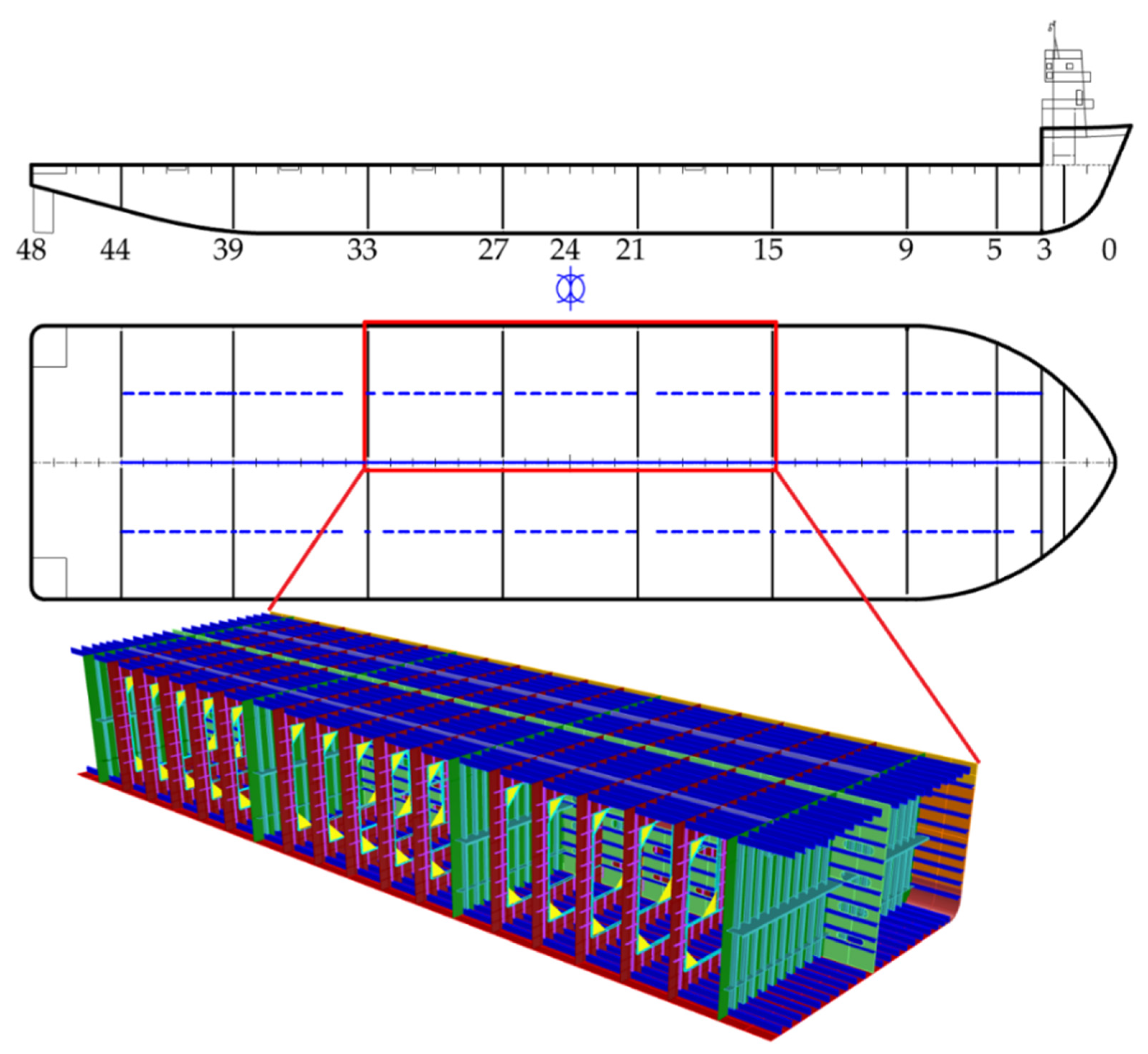
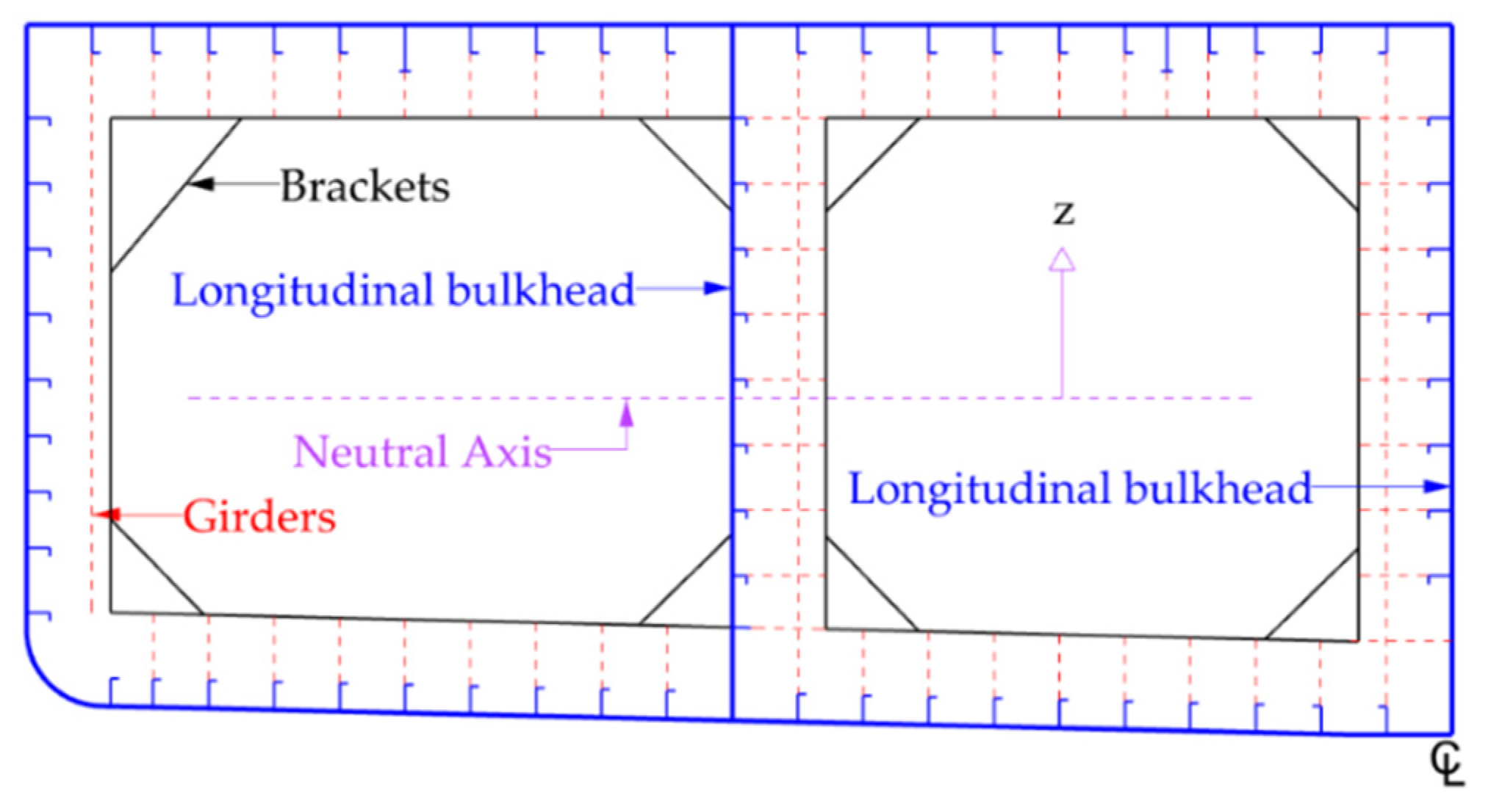
2. Modeling the Barge Midship Section
2.1. Description of the Barge
2.2. Lloyd’s Register Rules
2.2.1. Minimum Thickness of Deck Plates
2.2.2. Permissible Hull Vertical Bending Stresses
2.2.3. Hull Section Modulus
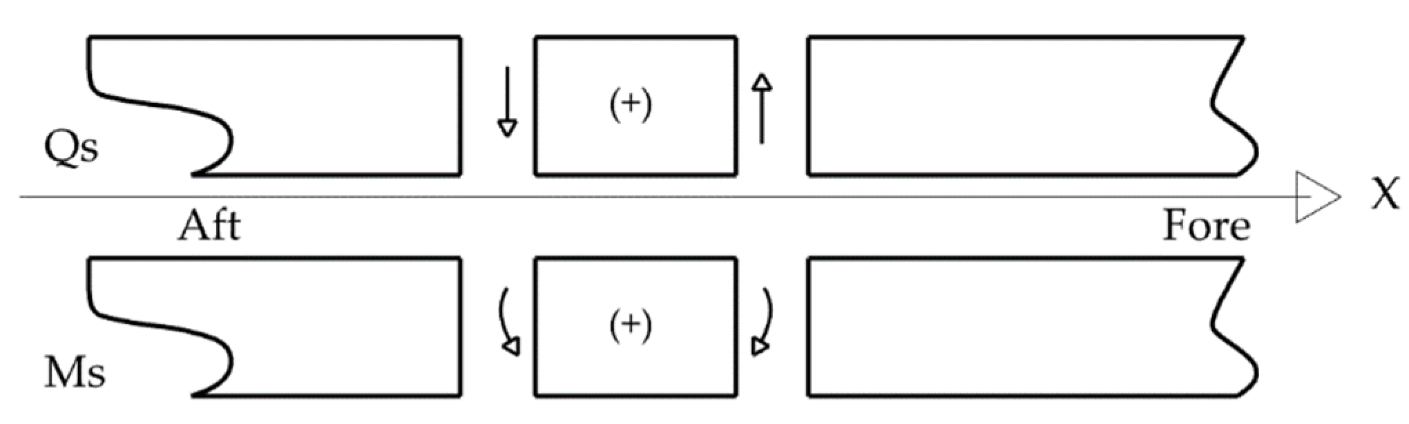
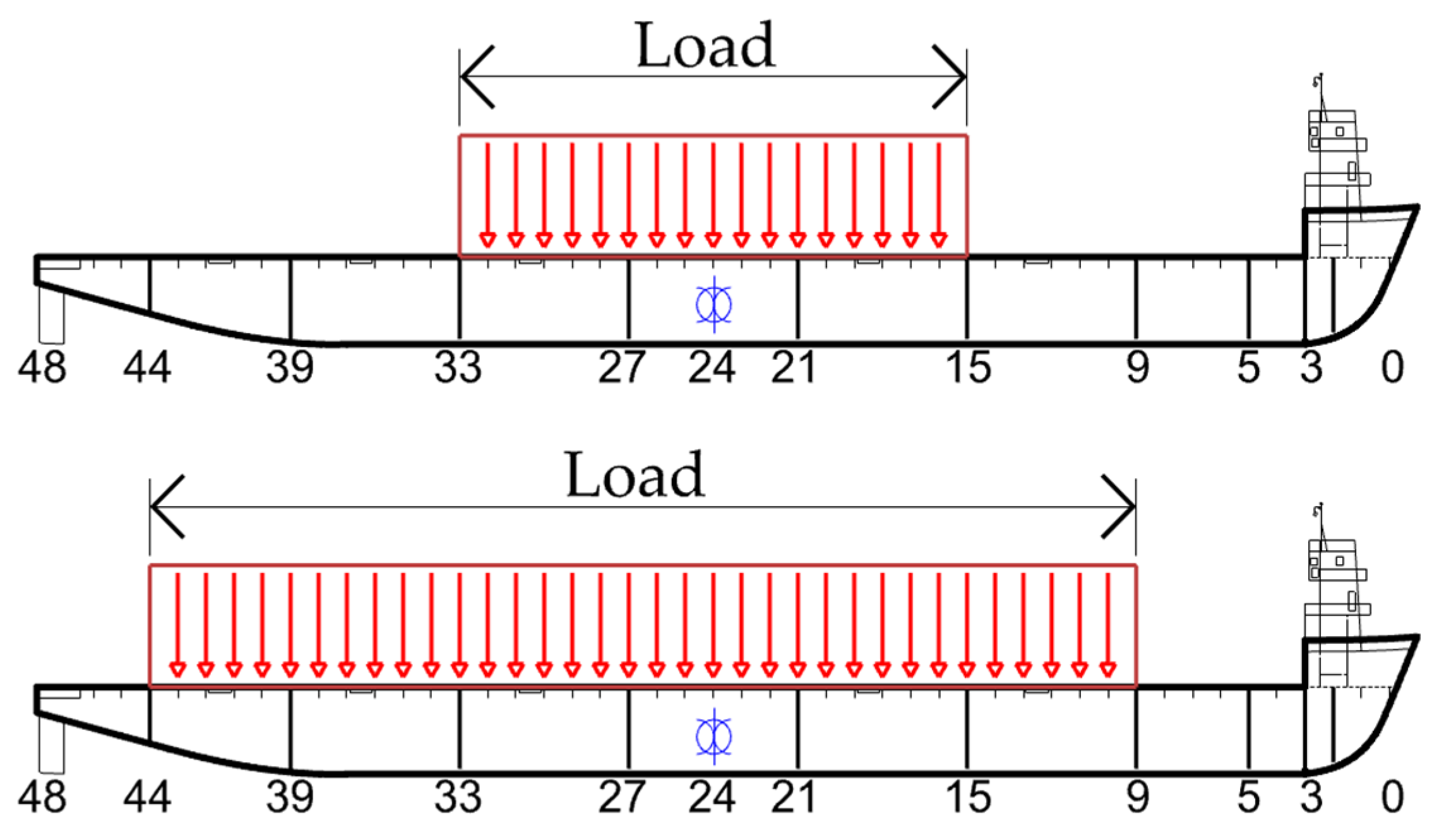
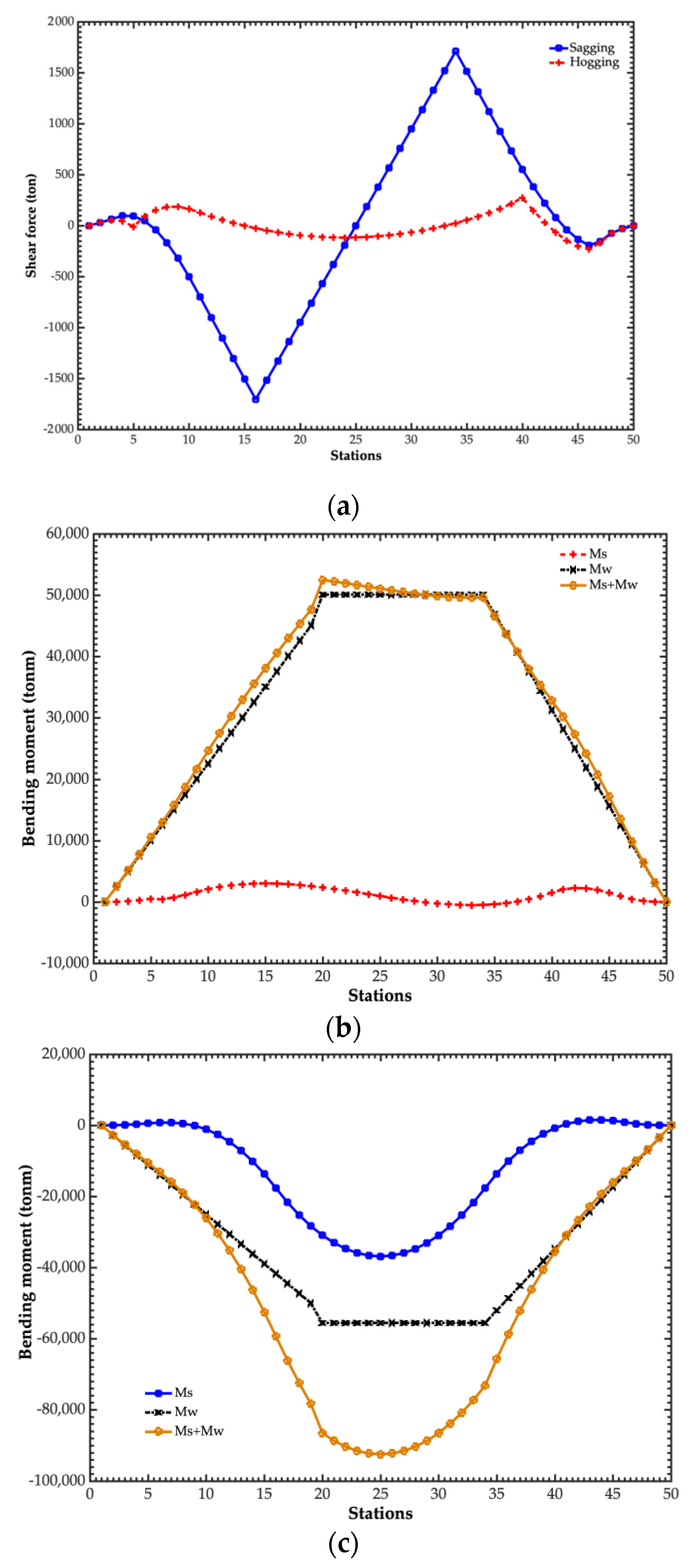
2.2.4. Still Water Shear Forces and Vertical Bending Moments
2.2.5. Vertical Wave Bending Moment
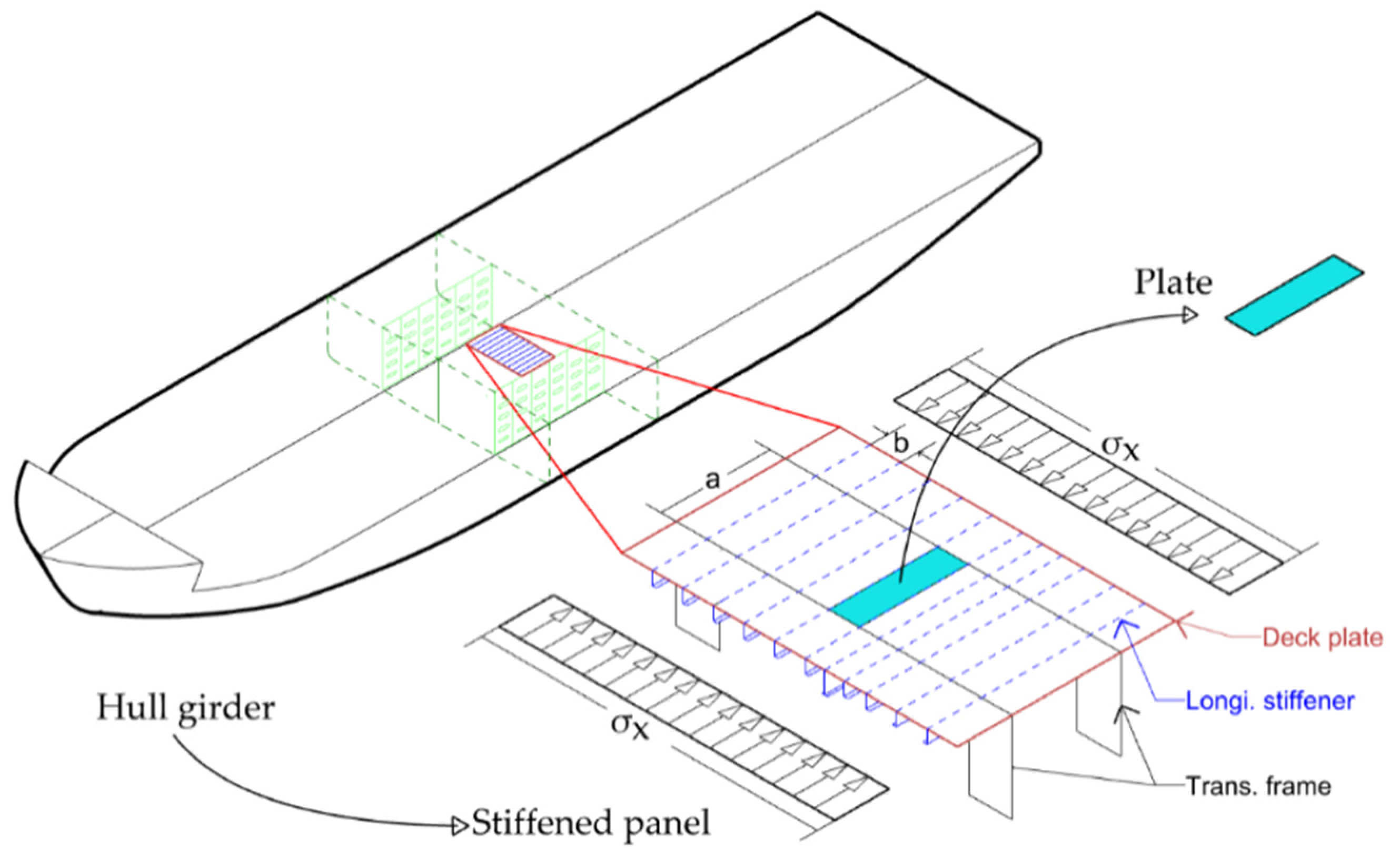
3. Buckling and Ultimate Strength of Ship Structure
Empirical Formulas for Stiffened Panels and Unstiffened Plates
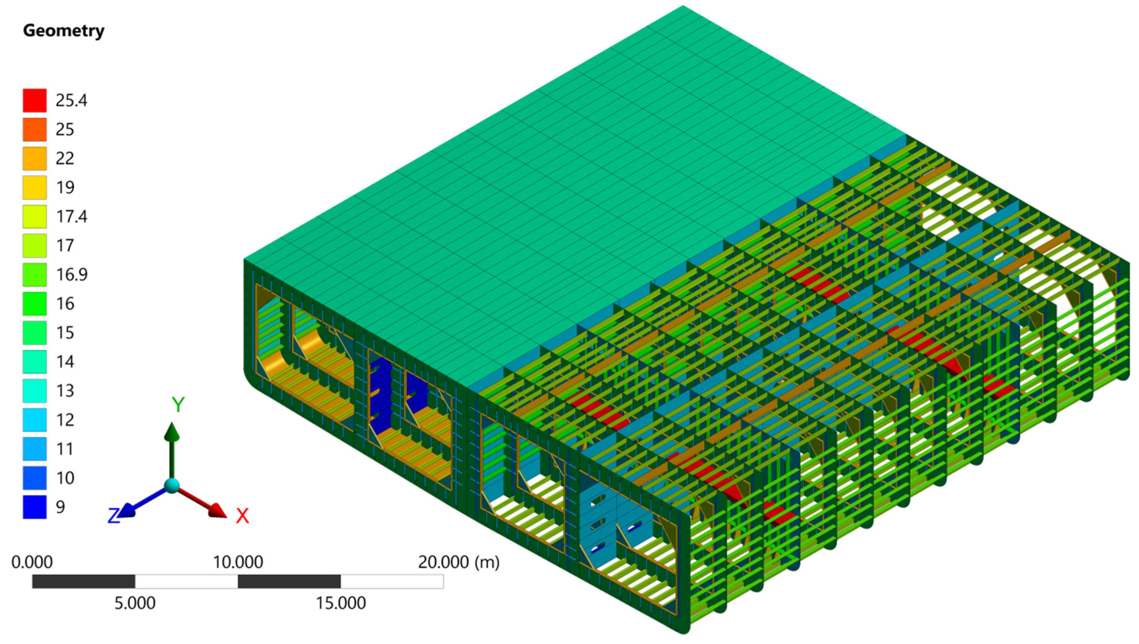
4. FEM Models of Midship Section
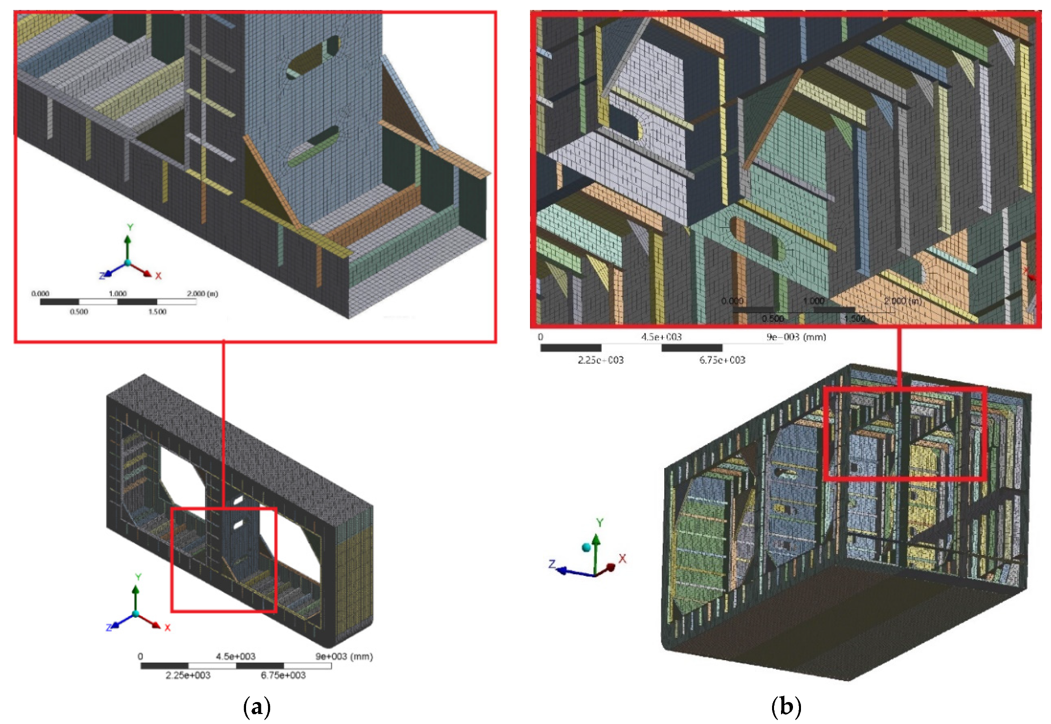
- (i)
- The length of one mesh element between each longitudinal stiffener must not be greater than two longitudinal spaces.
- (ii)
- The free edge on large brackets of the primary members must have a fine mesh to avoid unreal high stress due to discontinuities in geometry. In general, a mesh size equal to the spacing of the stiffener is recommended.
4.1. Verification of the FEM Model
- (i)
- Element thickness: the total thickness of the plate is correctly defined. Duplicate elements can cause incorrect plate thickness and element properties.
- (ii)
- Element shape: model elements should be examined in unconnected free edges, nodes, and coincident elements.
- (iii)
- Commonly, the tolerance limits of the model are the follows: aspect ratio should be less than 3, taper should be less than 10, warping should be less than 5 degrees, internal angle should be not less than 30 degrees, no free edge caused by wrong element connectivity, and coincident (duplicated) nodes should be checked and merged.
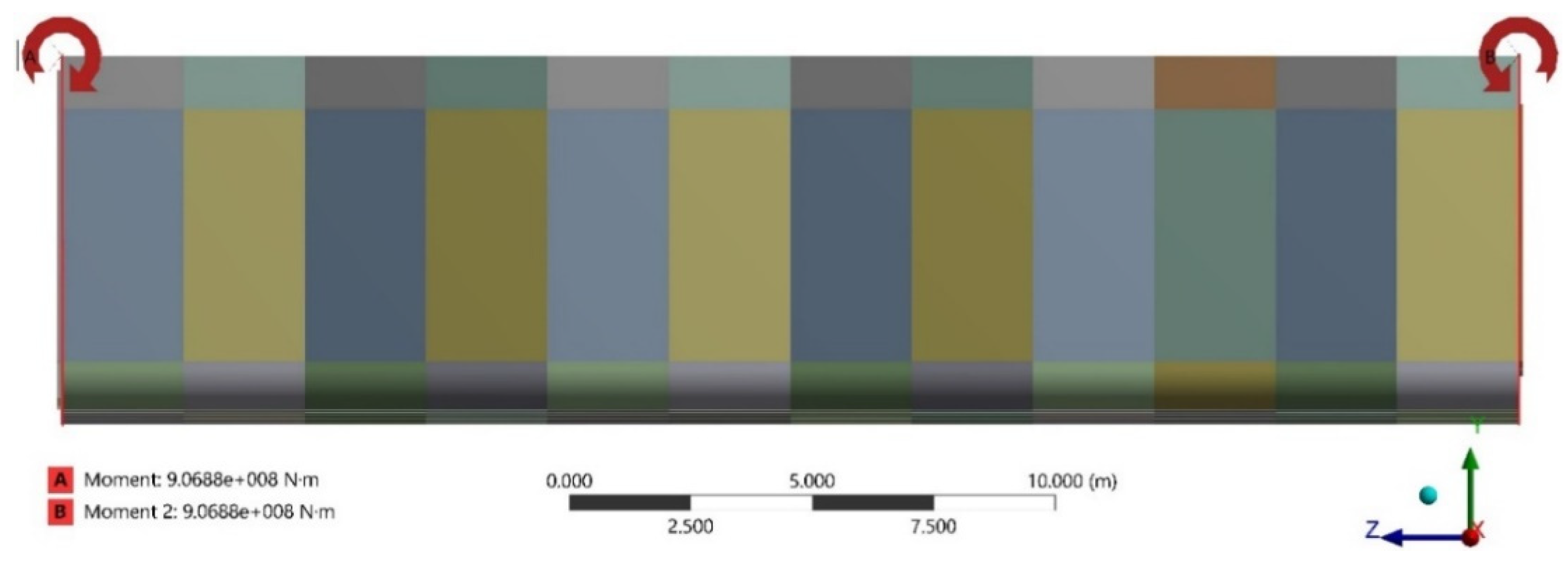
4.2. Total Vertical Bending Moment
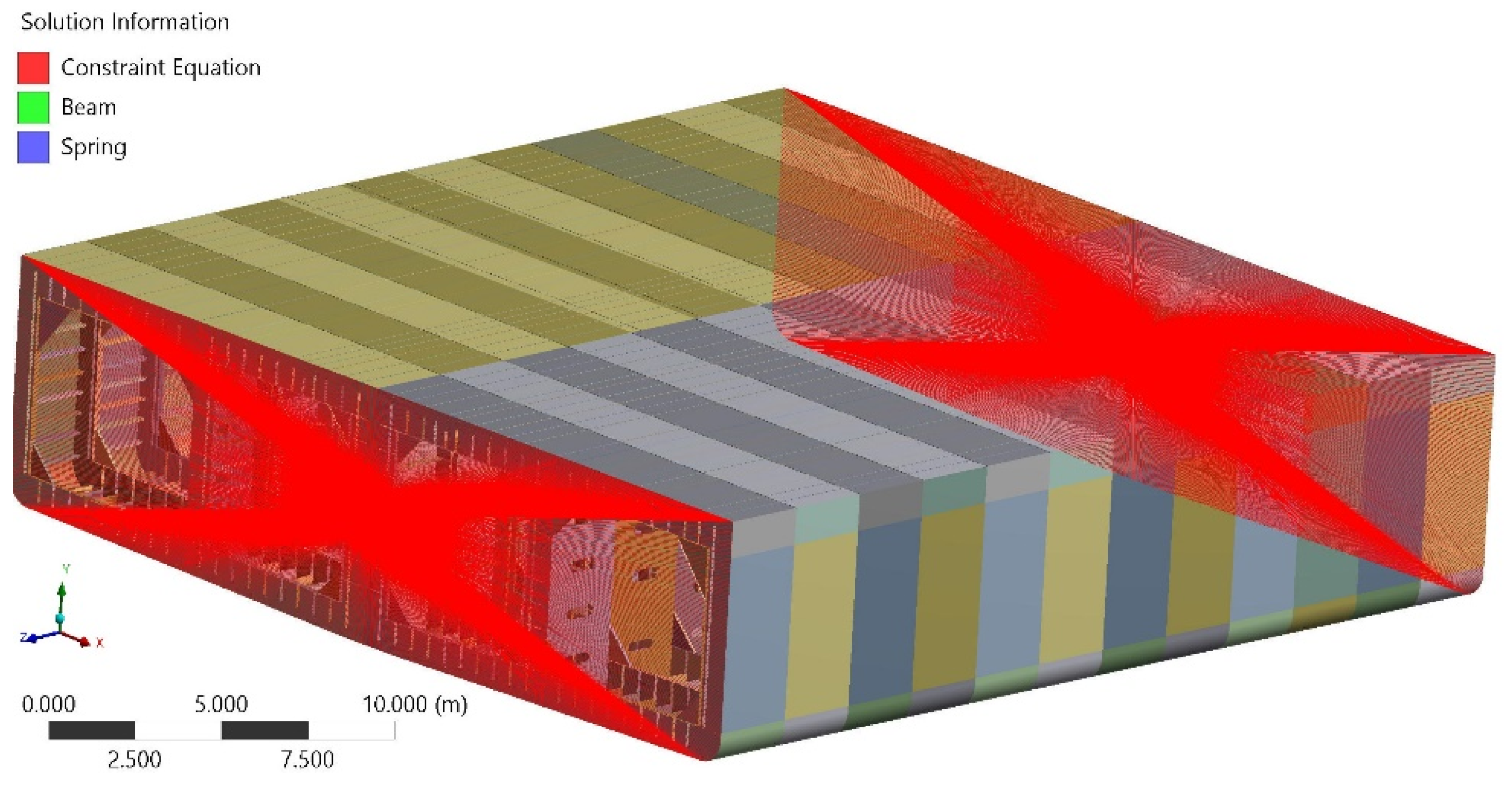
4.3. Boundary Conditions
4.4. Utilization Factor
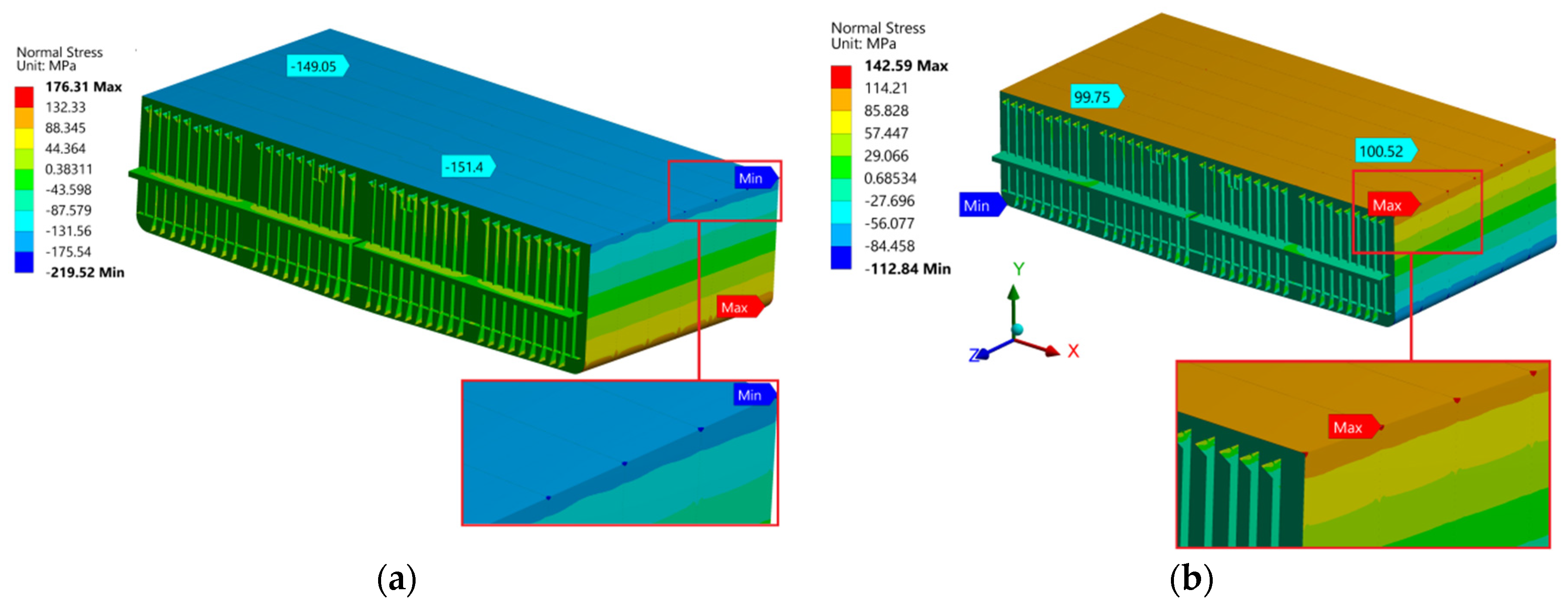
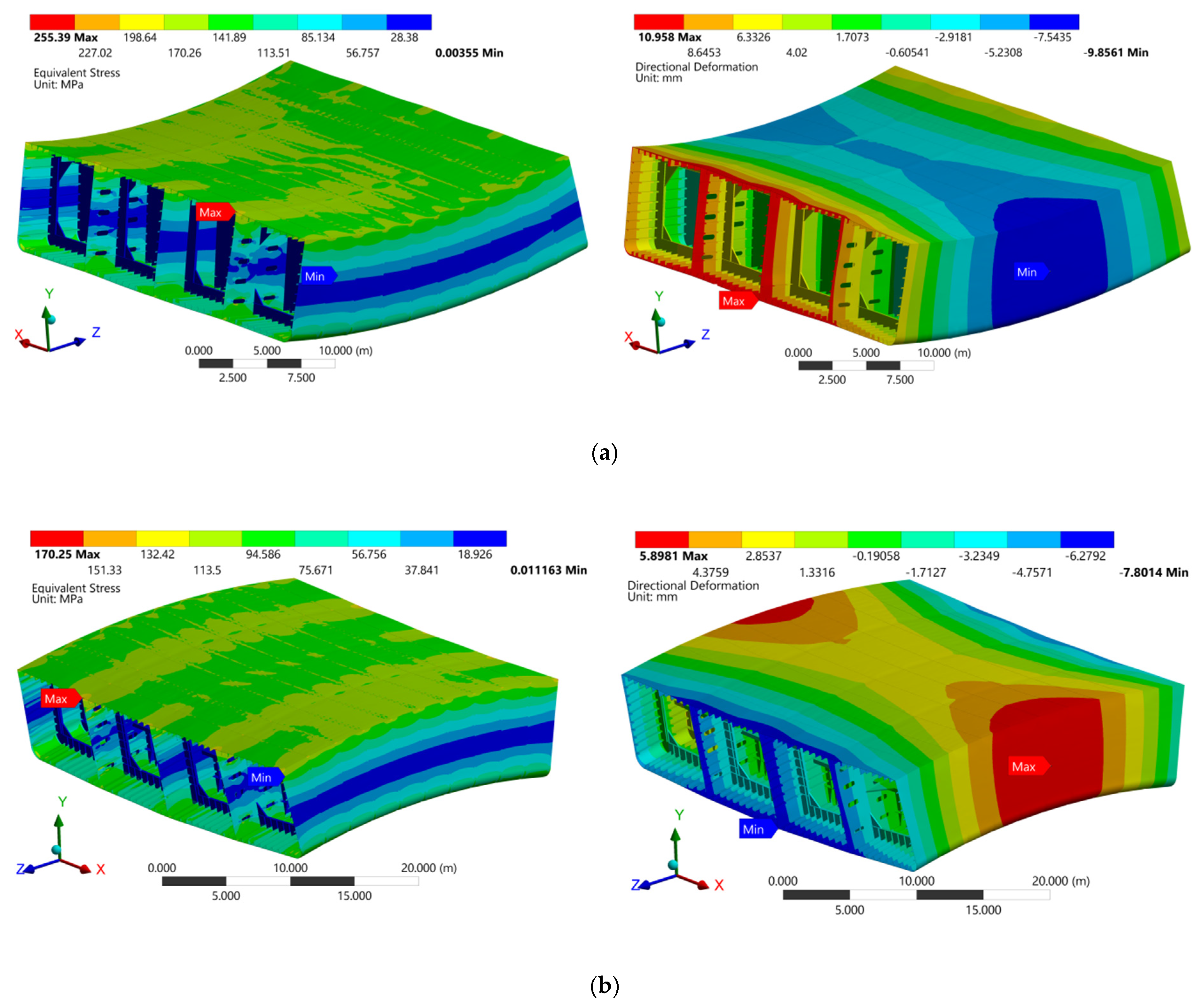
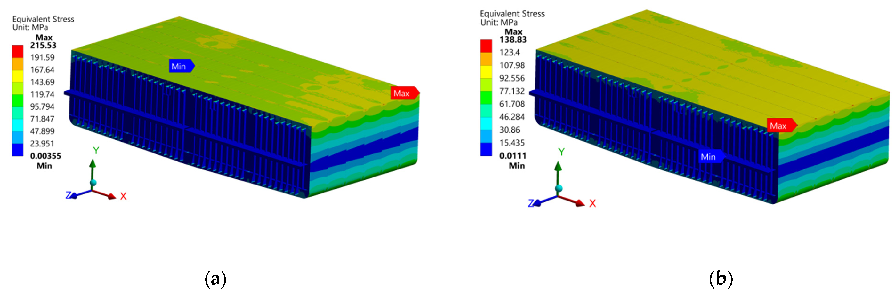
5. Results and Discussion
6. Conclusions
Author Contributions
Funding
Institutional Review Board Statement
Informed Consent Statement
Data Availability Statement
Conflicts of Interest
References
- Yao, T. Hull girder strength. Mar. Struct. 2003, 16, 1–13. [Google Scholar] [CrossRef]
- Tayyar, G.T. Overall hull girder nonlinear strength monitoring based on inclinometer sensor data. Int. J. Nav. Arch. Ocean Eng. 2020, 12, 902–909. [Google Scholar] [CrossRef]
- Bai, Y.; Jin, W.-L. Marine Structural Design; Elsevier BV: Amsterdam, The Netherlands, 2016. [Google Scholar]
- Okumoto, Y.; Takeda, Y.; Mano, M.; Okada, T. Design of Ship Hull Structures: A Practical Guide for Engineers; Springer: Berlin/Heidelberg, Germany, 2009. [Google Scholar]
- Shama, M. Buckling of Ship Structures; Springer Science and Business Media LLC.: Berlin/Heidelberg, Germany, 2013. [Google Scholar]
- Lloyd’s Register. Rules and Regulations for the Classification of Ships; Lloyd’s Register: London, UK, 2020. [Google Scholar]
- American Bureau of Shipping. Rules for Building and Classing Marine Vessels; American Bureau of Shipping: Houston, TX, USA, 2018. [Google Scholar]
- Ma, J.; Xiao, J.; Ma, R.; Cao, K. FPSO global strength and hull optimization. J. Mar. Sci. Appl. 2014, 13, 55–61. [Google Scholar] [CrossRef]
- Majeed, F. Design optimization of floating production storage and offloading platform (FPSO): A rational based approach. In Proceedings of the 2018 15th International Bhurban Conference on Applied Sciences and Technology (IBCAST), Islamabad, Pakistan, 9–13 January 2018; pp. 687–696. [Google Scholar]
- Mikkola, T.P.J.; Lillemäe, I.; Mazerski, G.; Taponen, T.; Ziółkowski, J.; Tamborski, L.; Dominiczak, P. FPSO hull structural design concept supporting controlled project execution. Mar. Syst. Ocean Technol. 2012, 7, 117–125. [Google Scholar] [CrossRef]
- Servis, D.; Voudouris, G.; Samuelides, M.; Papanikolaou, A. Finite element modelling and strength analysis of hold No. 1 of bulk carriers. Mar. Struct. 2003, 16, 601–626. [Google Scholar] [CrossRef]
- Lloyd´s Register. ShipRight Procedure for Ship Units. Appendix B Finite Element Analysis; Lloyd´s Register: London, UK, July 2014. [Google Scholar]
- ABS. Guidance Notes on Safehull Finite Element Analysis of Hull Structures; American Bureau of Shipping: Houston, YX, USA, 2004. [Google Scholar]
- Rörup, J.; Darie, I.; Maciolowski, B. Strength analysis of ship structures with open decks. Ships Offshore Struct. 2017, 12, S189–S199. [Google Scholar] [CrossRef]
- Kim, D.K.; Kim, H.B.; Zhang, X.; Li, C.G.; Paik, J.K. Ultimate strength performance of tankers associated with industry corrosion addition practices. Int. J. Nav. Arch. Ocean Eng. 2014, 6, 507–528. [Google Scholar] [CrossRef] [Green Version]
- IACS. Common Structural Rules for Bulk Carriers and Oil Tankers; International Association of Classification Societies: London, UK, 2020. [Google Scholar]
- Paik, J.K.; Kim, D.K.; Kim, M.S. Ultimate strength performance of suezmax tanker structures: Pre-CSR versus CSR designs. In Book Analysis and Design of Marine Structures, 1st ed.; Guedes, S.C., Das, P.K., Eds.; Taylor & Francis Group: London, UK, 2009; Volume 3, pp. 181–190. [Google Scholar]
- IACS. Longitudinal Strength Standard; UR S11, Rev.9; IACS: London, UK, June 2019. [Google Scholar]
- Soares, C.G. On the Definition of rule requirements for wave induced vertical bending moments. Mar. Struct. 1996, 9, 409–425. [Google Scholar] [CrossRef]
- Parunov, J.; Senjanovi, I.; Paviaeeviae, M. Use of vertical wave bending moments from hydrodynamic analysis In Design of Oil Tankers. Int. J. Marit. Eng. 2004, 146, 51–64. [Google Scholar] [CrossRef]
- Zhang, S. A review and study on ultimate strength of steel plates and stiffened panels in axial compression. Ships Offshore Struct. 2015, 11, 1–11. [Google Scholar] [CrossRef]
- Kim, D.K.; Lim, H.L.; Yu, S.Y. A technical review on ultimate strength prediction of stiffened panels in axial compression. Ocean Eng. 2018, 170, 392–406. [Google Scholar] [CrossRef]
- Kim, D.K.; Lim, H.L.; Yu, S.Y. Ultimate strength prediction of T-bar stiffened panel under longitudinal compression by data processing: A refined empirical formulation. Ocean Eng. 2019, 192, 106522. [Google Scholar] [CrossRef]
- Kim, D.K.; Yu, S.Y.; Lim, H.L.; Cho, N.-K. Ultimate Compressive Strength of Stiffened Panel: An Empirical Formulation for Flat-Bar Type. J. Mar. Sci. Eng. 2020, 8, 605. [Google Scholar] [CrossRef]
- Lin, Y.T. Ship Longitudinal Strength Modeling. Ph.D. Thesis, Department of Naval Architecture and Ocean Engineering, University of Glasgow, Glasgow, Scotland, 1985. [Google Scholar]
- Paik, J.K.; Thayamballi, A.K. An Empirical Formulation for Predicting the Ultimate Compressive Strength of Stiffened Panels. In Proceedings of the Seventh International Offshore and Polar Engineering Conference, Honolulu, HI, USA, 25–30 May 1997. [Google Scholar]
- Paik, J.K.; Thayamballi, A.K. Ultimate Limit State Design of Steel-Plated Structures; Wiley: Chichester, UK, 2003. [Google Scholar]
- Zhang, S.; Khan, I. Buckling and ultimate capability of plates and stiffened panels in axial compression. Mar. Struct. 2009, 22, 791–808. [Google Scholar] [CrossRef]
- Xu, M.C.; Song, Z.J.; Zhang, B.W.; Pan, J. Empirical formula for predicting ultimate strength of stiffened panel of ship structure under combined longitudinal compression and lateral loads. Ocean Eng. 2018, 162, 161–175. [Google Scholar] [CrossRef]
- Kim, D.; Lim, H.; Kim, M.; Hwang, O.; Park, K. An empirical formulation for predicting the ultimate strength of stiffened panels subjected to longitudinal compression. Ocean Eng. 2017, 140, 270–280. [Google Scholar] [CrossRef]
- Cui, W.; Mansour, A.E. Effects of welding distortions and residual stresses on the ultimate strength of long rectangular plates under uniaxial compression. Mar. Struct. 1998, 11, 251–269. [Google Scholar] [CrossRef]
- Faulkner, D. A review of effective plating for use in the analysis of stiffened plating in bending and compression. J. Ship Res. 1975, 19, 1–17. [Google Scholar] [CrossRef]
- Kim, D.K.; Poh, B.Y.; Lee, J.R.; Paik, J.K. Ultimate strength of initially deflected plate under longitudinal compression: Part I = An advanced empirical formulation. Struct. Eng. Mech. 2018, 68, 247–259. [Google Scholar]
- Lloyd´s Register. ShipRight Procedure for Ship Units. In Appendix A Strength Assessment; Lloyd´s Register: London, UK, July 2014. [Google Scholar]
- Lloyd´s Register. ShipRight Structural Design Assessment. In Primary Structure of Tankers Guidance on Direct Calculations; Lloyd´s Register: London, UK, 2004. [Google Scholar]


| Parameters | Value | Unit |
|---|---|---|
| Overall length | 122.45 | m |
| Loadline length (L) | 119.95 | m |
| Breadth (B) | 30.5 | m |
| Depth (D) | 7.60 | m |
| Loadline draft (T) | 6.21 | m |
| Deadweight | 15,550 | ton |
| Terms | Coefficients | |
|---|---|---|
| T-bar | Flat-bar | |
| C0 | −0.1449 | −1.5721 |
| C1 | 2.9787 | 5.6591 |
| C2 | −2.6098 | −3.7336 |
| C3 | −0.2418 | −0.6934 |
| C4 | 1.2374 × 10⁻³ | −1.8581 × 10⁻² |
| C5 | 1.3470 × 10⁻³ | 1.7858 × 10⁻² |
| C6 | 0.8841 | 1.3546 |
| C7 | −0.3361 | −0.3482 |
| C8 | 1.5975 × 10⁻³ | −1.9443 × 10⁻³ |
| C9 | 2.7745 × 10⁻³ | 0.8850 × 10⁻³ |
| C10 | −7.5919 × 10⁻³ | 1.8299 × 10⁻² |
| C11 | 3.2442 × 10⁻⁵ | −1.2316 × 10⁻⁴ |
| C12 | 4.9670 × 10⁻⁵ | 1.4994 × 10⁻⁴ |
| C13 | 1.3267 × 10⁻² | −1.8752 × 10⁻⁴ |
| C14 | −5.4149 × 10⁻⁵ | −1.6306 × 10⁻⁵ |
| 0.025 (slight level) | −10.749 | 31.246 | −37.009 | 0.480 |
| 0.05 | −2.948 | 8.138 | −13.839 | −0.368 |
| 0.10 (average level) | −0.029 | 0.322 | −4.680 | −0.745 |
| 0.15 | 0.735 | −1.554 | −2.172 | −0.859 |
| 0.20 | 1.064 | −2.321 | −1.060 | −0.912 |
| 0.25 | 1.241 | −2.719 | −0.448 | −0.943 |
| 0.30 (severe level) | 1.349 | −2.956 | −0.068 | −0.963 |
| Condition | Wave | Still Water | Total | Status | |
|---|---|---|---|---|---|
| MW | MS | MV | |||
| Sagging | −55583 | −36861 | 43610 | −92444 | OK |
| Hogging | 50102 | 10968 | 44702 | 61070 | OK |
| Section Modulus (m3) | Moment of Inertia (m4) at Midship Section | Deck Plate Thickness (mm) | Status | ||||
|---|---|---|---|---|---|---|---|
| ZD | ZB | Zmin | INA | Imin | t | tmin | |
| 5.338 | 5.974 | 4.961 | 21.426 | 17.247 | 14 | 9.562 | OK |
| Hull Vertical Bending Stresses (MPa) | |||||||
| Results | Permissible | ||||||
| Condition | |||||||
| Sagging | 174.23 | 155.68 | 182.29 | OK | |||
| Hogging | 112.24 | 100.28 | 182.29 | OK | |||
| Maximum Stress | Yield Utilization Factor | Status | |||
|---|---|---|---|---|---|
| Condition | Yield stress (MPa) [6,11] | von Mises stress (MPa) | Design | Permissible [34] | |
| Sagging | 250 | 215.53 | 0.86 | 0.9 | OK |
| Hogging | 250 | 138.83 | 0.55 | 0.9 | OK |
| Parameter | Value | Unit | Details | |
|---|---|---|---|---|
| Deck | Bottom | |||
| 2500 | 2500 | mm | Length of stiffener and plate | |
| 700 | 700 | mm | Breadth of plate | |
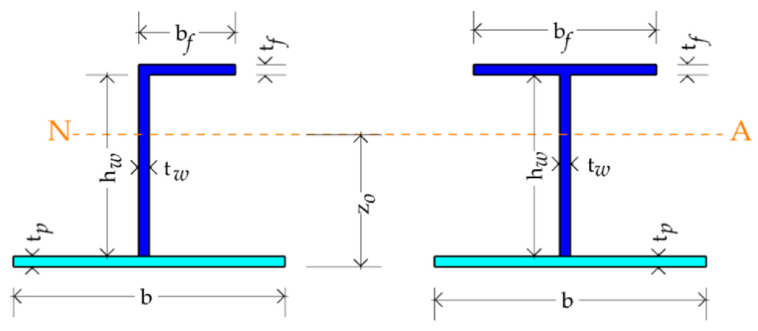
| 90 | 90 | mm | Breadth of flange | |
| 17.4 | 17.4 | mm | Thickness of flange | |
| 282.6 | 282.6 | mm | Height of web | |
| 17.4 | 17.4 | mm | Thickness of web | |
| 14 | 22 | mm | Thickness of plate | |
| 108.733 | 100.784 | mm | Radius of gyration | |
| 0.2588 | 0.2792 | − | Column slenderness ratio | |
| 1.7678 | 1.1249 | − | Plate slenderness ratio | |
| 250 | 250 | MPa | Yield strength of plate | |
| 250 | 250 | MPa | Equivalent yield strength | |
| 200 | 200 | GPa | Elastic modulus | |
| Panel | Ultimate Strength Compressive Stresses | Working Stresses (MPa) | ||
|---|---|---|---|---|
| Deck (sagging) | Lin [25] | 198.06 | 175.54 | 1.13 |
| Paik and Thayamballi [26,27] | 195.94 | 175.54 | 1.12 | |
| Zhang and Khan [28] | 211.74 | 175.54 | 1.21 | |
| Xu et al. [29] | 207.34 | 175.54 | 1.18 | |
| Kim et al. [30] | 187.35 | 175.54 | 1.07 | |
| Kim et al. [23] | 208.86 | 175.54 | 1.19 | |
| Lloyd’s Register [6] | 248.35 | 175.54 | 1.41 | |
| Bottom (hogging) | Lin [25] | 222.58 | 112.84 | 1.97 |
| Paik and Thayamballi [26,27] | 219.16 | 112.84 | 1.94 | |
| Zhang and Khan [28] | 239.88 | 112.84 | 2.13 | |
| Xu et al. [29] | 235.82 | 112.84 | 2.09 | |
| Kim et al. [30] | 202.69 | 112.84 | 1.80 | |
| Kim et al. [23] | 232.71 | 112.84 | 2.06 | |
| Lloyd’s Register [6] | 248.08 | 112.84 | 2.20 | |
| Plate | Ultimate Strength Compressive Stresses (MPa) | |||
|---|---|---|---|---|
| Deck (sagging) | Faulkner [32] | 202.84 | 175.54 | 1.16 |
| Cui and Mansour [31] | 209.07 | 175.54 | 1.19 | |
| Kim et al. (severe level) [33] | 171.48 | 175.54 | 0.98 | |
| Kim et al. (average level) [33] | 199.44 | 175.54 | 1.13 | |
| Kim et al. (slight level) [33] | 224.96 | 175.54 | 1.28 | |
| Lloyd’s Register [6] | 195.75 | 175.54 | 1.12 | |
| Bottom (hogging) | Faulkner [32] | 246.92 | 112.84 | 2.19 |
| Cui and Mansour [31] | 224.19 | 112.84 | 1.99 | |
| Kim et al. (severe level) [33] | 220.80 | 112.84 | 1.96 | |
| Kim et al. (average level) [33] | 245.57 | 112.84 | 2.17 | |
| Kim et al. (slight level) [33] | 249.99 | 112.84 | 2.22 | |
| Lloyd’s Register [6] | 228.03 | 112.84 | 2.02 | |
Publisher’s Note: MDPI stays neutral with regard to jurisdictional claims in published maps and institutional affiliations. |
© 2021 by the authors. Licensee MDPI, Basel, Switzerland. This article is an open access article distributed under the terms and conditions of the Creative Commons Attribution (CC BY) license (http://creativecommons.org/licenses/by/4.0/).
Share and Cite
Salazar-Domínguez, C.M.; Hernández-Hernández, J.; Rosas-Huerta, E.D.; Iturbe-Rosas, G.E.; Herrera-May, A.L. Structural Analysis of a Barge Midship Section Considering the Still Water and Wave Load Effects. J. Mar. Sci. Eng. 2021, 9, 99. https://0-doi-org.brum.beds.ac.uk/10.3390/jmse9010099
Salazar-Domínguez CM, Hernández-Hernández J, Rosas-Huerta ED, Iturbe-Rosas GE, Herrera-May AL. Structural Analysis of a Barge Midship Section Considering the Still Water and Wave Load Effects. Journal of Marine Science and Engineering. 2021; 9(1):99. https://0-doi-org.brum.beds.ac.uk/10.3390/jmse9010099
Chicago/Turabian StyleSalazar-Domínguez, Cristian M., José Hernández-Hernández, Edna D. Rosas-Huerta, Gustavo E. Iturbe-Rosas, and Agustín L. Herrera-May. 2021. "Structural Analysis of a Barge Midship Section Considering the Still Water and Wave Load Effects" Journal of Marine Science and Engineering 9, no. 1: 99. https://0-doi-org.brum.beds.ac.uk/10.3390/jmse9010099