Article

Analytical Modeling and Design of Novel Conical Halbach Permanent Magnet Couplings for Underwater Propulsion

1
School of Marine Science and Technology, Northwestern Polytechnical University, Xi’an 710072, China
2
School of Electrical and Data Engineering, University of Technology Sydney, Sydney 2007, NSW, Australia
*
Author to whom correspondence should be addressed.
J. Mar. Sci. Eng. 2021, 9(3), 290; https://0-doi-org.brum.beds.ac.uk/10.3390/jmse9030290
Submission received: 5 February 2021 / Revised: 26 February 2021 / Accepted: 4 March 2021 / Published: 6 March 2021
(This article belongs to the Section Ocean Engineering)

Abstract

:
Permanent magnet couplings can convert a dynamic seal into a static seal, thereby greatly improving the stability of the underwater propulsion unit. In order to make full use of the tail space and improve the transmitted torque capability, a conical Halbach permanent magnet coupling (C-HPMC) is proposed in this paper. The C-HPMC combines multiple cylindrical HPMCs with different sizes into an approximately conical structure. Compared with the conical permanent magnet couplings in our previous work, the novel C-HPMC has better torque performance and is easy to process. The analytical calculation method of transmitted torque of C-HPMC is proposed on the basis of torque calculation of the three common types of HPMCs. The accuracy of the torque calculation of the three HPMCs is verified, and the torque performance of the three HPMCSs of different sizes is compared and discussed. The “optimal type selection” method is proposed and applied in the design of C-HPMC. Finally, on the basis of torque analysis calculation and axial force calculation, a complete flowchart of the design and performance analysis of C-HPMC is described.

1. Introduction

With the rapid development of marine science and technology, a variety of underwater vehicles are helping humankind to continue to explore the ocean, comprehend the ocean, and make use of the ocean [1,2,3]. The deep-sea environment, with highly corrosive and high hydrostatic pressure, has brought many challenges to the development of high-performance underwater vehicles. One of the most common problems is the sealing of the output shaft. Traditional mechanical seals have complex structures, serious mechanical losses, and low reliability, so it is difficult to ensure the normal operation of internal electrical components, especially in the deep-sea environment. As a useful solution for the shaft sealing, permanent magnet couplings (PMCs) have been widely used in underwater equipment, chemical and nuclear power, and other industrial applications in recent years [4,5].
PMCs use magnetic force to realize non-contact torque transmission, which can convert the dynamic seal into a static seal, thus greatly improving the security and stability of the seal [6,7]. The application of PMCs is closely related to the research and development of rare-earth permanent magnets. According to the magnetization direction of permanent magnets, existing PMCs can be broadly classified into cylindrical PMCs and axial PMCs [8,9,10,11,12]. For PMC, it is generally required to achieve a given maximum transmitted torque with a minimum volume of permanent magnets [13]. In the initial design, the maximum transmitted torque is one of the most important characteristics of PMCs. Some classical analytical methods and finite element analysis (FEA) methods are employed to calculate the torque performance of PMCs in the very early research [6,14], and the optimization designs are carried out based on those calculation methods [9,10,15,16]. In addition to the maximum transmitted torque, the inertia, weight, and cost are also the main specifications for the design of PMCs. Directly adopting an ironless structure can reduce the inertia and weight, but it will also affect the torque performance of PMC [4,11,17].
It is well known that the Halbach array is a special magnetization method for permanent magnets, which offer many attractive features, such as sinusoidal airgap field distribution, potentially high airgap flux density, and self-shielding magnetization [18,19,20,21,22]. In recent years, more attention in research has been given to the application of the Halbach array in magnetic machines, since it is an effective way to improve the performance [23,24,25]. The PMC with Halbach array has attracted great interest, because it can improve torque performance while reducing the mass and inertia [26,27]. The PMC is defined with Halbach magnetized outer rotor as Halbach permanent magnet couplings (HPMCs). There are three common HPMCs, which adopt radial, parallel, and Halbach magnetized inner rotors, respectively. In [28], the transmitted torque of the HPMC with Halbach magnetized inner and outer rotors is calculated and compared with that of the traditional parallel magnetized PMC by analytical method, finding that the HPMC requires a significantly lower magnet volume to produce the same transmitted torque as the parallel magnetized PMC. The analytical torque calculation method of the HPMC using a segmented Halbach array for both inner and outer rotors was established in [29]. An HPMC with a radially magnetized inner rotor was designed and optimized in [7].
Streamlined revolved body is one of the most common structural forms of underwater vehicles, and it has a conical tail segment, as shown in Figure 1a. The underwater propulsion unit chosen is generally radial PMC, which is mounted in the tail segment, as shown in Figure 1b. Most of the existing HPMCs do not take into consideration the special needs of the underwater propulsion and thus have many limitations in performance improvement. In our previous work [30], a conical permanent magnet coupling is first proposed, matching the tail segment space of the underwater vehicle so as to can make full use of the tail space to improve the torque performance. However, its application in engineering is greatly limited because of the use of irregular permanent magnets. Taking the practical situation of the engineering application into account and improving performance at the same time, a novel conical Halbach permanent magnet coupling (C-HPMC) is proposed. The C-HPMC combines multiple cylindrical HPMCs with different sizes into an approximately conical structure, which can make full use of the tail space and is easy to process (Figure 1c).
In this paper, features of C-HPMCs are analyzed and the analytical model is established. The analytical calculation method of transmitted torque of C-HPMC is proposed on the basis of torque calculation of the three common types of HPMCs. The accuracy of the torque calculation of the three HPMCs is verified, and the torque performance of the three HPMCSs of different sizes is compared and analyzed. The “optimal type selection” method is proposed and applied in the design of C-HPMC. A research case of C-HPMC is established under certain prefixed geometric parameter constraints, and the specific design and analysis process is given.

2. Topologies and Features of C-HPMC

The PMC for underwater propulsion is mounted in the tail segment of underwater vehicles. The inner rotor is connected with the motor output shaft, and the outer rotor drives the propeller. Non-contact torque transmission between the inner and outer rotors is achieved by the permanent magnet magnetic force. The tail segment of underwater vehicles is simplified to a simple conical space. It can be seen from Figure 2a that the traditional cylindrical PMC cannot make full use of this space. Figure 2b shows the structure of the proposed C-HPMC, which is composed of multiple cylindrical HPMCs with different sizes.
If the traditional cylindrical PMC is used in the tail segment, the relationship between the outer diameter D a and the axial length is as follows:
D a = D s 2 × L a × tan α
where D s is the outer diameter of the tail conical space, L a is the axial length of PMC, and α is the half cone angle. It is assumed that the C-HPMC is divided into N modules, and each module has the same axial length. Then, the outer diameter of the nth HPMC D a n can be expressed as:
D a n = D s 2 × n × L s N × tan α
where L s is the axial length of the tail conical space.
When designing a PMC, the size of the outer rotor is usually restricted, but the inner space is often sufficient. Choosing the Halbach magnetized outer rotor can help to make full use of outer rotor space and improve the ability of the transmitted torque. There are three common HPMCs, which adopt radial, parallel, and Halbach magnetized inner rotors respectively, as shown in Figure 3a–c. In the present study, considering the difficulty of processing, the two-segment Halbach magnetized PMs are used in HPMCs. The only difference among the three HPMCs is the magnetization direction of the inner rotor PMs. μ r is the relative magnetic permeability, R i r is the inner radius of PMCs, R o r is the outer radius of PMCs, R 1 is the inner radius of inner PMs, R 2 is the outer radius of inner PMs, R 3 is the inner radius of outer PMs, R 4 is the outer radius of outer PMs, θ m is the angle of the main pole, θ p is the pole pitch, θ o is the arc length of PMs. For the two-segment Halbach magnetized rotors, the PMs can be divided into the main poles and the auxiliary poles. The ratio of the main pole can be expressed as:
R m p = θ m / θ p
θ p = π / p
In order to facilitate processing and save costs, the R m p is usually 0.5. For the radial and parallel magnetized rotors, the pole arc coefficient is defined as:
α p = θ o / θ p
For type-2 and type-3, the highest torque is achieved when α p is equal to 1. For all of the three types of HPMCs, the R m p of the initial Halbach magnetized inner rotors and outer rotors is 0.5. The geometrical parameters of the tail conical space and the initially designed C-HPMC are shown in Table 1. Both the inner and outer rotors use high-performance permanent magnet NdFeB, the residual magnetic flux density is 1.27 T, and the relative permeability is 1.1045.

3. Performance Analysis of the C-HPMC

The C-HPMC presented above adopts two methods to improve the torque transmission capacity of the propulsion system of underwater vehicles: one is the multi-module specially shaped structure, and the other is the usage of Halbach array PMs. The performance of the C-HPMC is the result of the combined action of multiple cylindrical HPMCs. There are three common HPMCs with different magnetized inner rotors. The comparative study of three types of HPMCs is the foundation for the design and optimization of C-HPMC.
The main function of the C-HPMC is to realize non-contact torque transmission, and hence the transmitted torque has always been a research focus. For underwater propulsion, the maximum transmitted torque is also the most important specification for the design of C-HPMC. At the same time, the propeller directly connected to the outer rotor of C-HPMC is used to convert the torque into thrust. A slight displacement of the propeller in the axial direction leads to an axial force that is opposed to this displacement. The novel C-HPMC proposed in this paper is expected to have more complex and comprehensive mechanical characteristics. It can be used as a coupling to transmit torque and as a passive axial bearing to maintain the propeller in its axial position, compensating the axial force related to thrust. Therefore, the axial force of the novel C-HPMC also needs to be carefully studied.

3.1. Transmitted Torque Calculation of the C-HPMC

The transmitted torque of PMCs can be analyzed by three-dimensional FEA (3D FEA) method or two-dimensional FEA (2D FEA) method. However, the FEA method is not suitable for the initial design and optimization design, especially when the calculation model size is large or the number of design parameters is large. Many samples with different design parameters need to be calculated in the initial design and optimization stage of the new prototype. When analyzing the influence of design parameters on the novel C-HPMC, it is more efficient to use analytical methods. The analytical method is helpful not only to solve the problem of computational cost and efficiency, but also to understand the design object fundamentally. Since the maximum transmitted torque directly determines the power output capability of the propulsion unit, it is necessary to analyze and optimize the torque performance of the C-HPMC. The analytical method based on accurate subdomain and Maxwell stress tensor will be used for transmitted torque calculation.
For the C-HPMC consisting of N HPMCs, the total transmitted torque T a is the sum of the transmitted torque of HPMCs:
T a = n = 1 N T n
where T n , the transmitted torque of the nth HPMC, can be expressed as:
T n = L n μ 0 r n 2 B n r ( r , θ ) × B n θ ( r , θ ) d θ  
where θ is the rotor position angle, r n is the radius of the airgap of the nth HPMC, L n is the axial length the nth HPMC, and B r n ( r , θ ) and B θ n ( r , θ ) are the radial and tangential components of the air gap flux density of the nth HPMC, respectively. The air gap flux density is jointly excited by the inner and outer rotor permanent magnets of the nth HPMC, so it can be expressed as:
B r n ( r , θ ) = B r i ( r , θ ) + B r o ( r , θ )
B θ n ( r , θ ) = B θ i ( r , θ ) + B θ o ( r , θ )
where B r i ( r , θ ) , B r o ( r , θ ) , B θ i ( r , θ ) , B θ o ( r , θ ) are the radial and tangential components of the air gap flux density when the inner and outer rotors are separately excited. The only difference between the rotors is the distribution of residual magnetization. When the magnetization mode of the permanent magnets is different, the analytical expression of the magnetization components M r and M θ are different. The three types of HPMCs include one type of outer rotor and three types of inner rotors, their waveforms are shown in Figure 4.
For the HPMCs, the airgap field produced by the outer and inner rotor is governed by Laplacian/quasi-Poissonian equations and boundary conditions. The analytical solution to the air gap flux density excited by a single inner rotor or outer rotor can refer to the analytical expression of the air gap magnetic field of ideal PM motors. The complete solution to the flux density components can be deduced from the general solution of Laplacian/quasi-Poissonian equations and the specified boundary conditions.
  • For the Halbach magnetized outer rotor:
    B r o ( r , θ ) = n = 1 , 3 , 5 K B o ( n ) f B r o ( r ) cos [ n p ( θ + ϕ ) ]
    B θ o ( r , θ ) = k = 1 , 3 , 5 K B o ( k ) f B θ o ( r ) sin [ k p ( θ + ϕ ) ]
    where,
    K B o ( n ) = μ 0 n p { M r n + M θ n n p 1 M r n M θ n n p + 1 ( R m i R m o ) 2 n p 2 ( M r n + n p M θ n ) ( n p ) 2 1 ( R m i R m o ) n p 1 } { [ ( μ r + 1 ) ( R i R m o ) 2 n p ( μ r 1 ) ( R m i R m o ) 2 n p ] [ ( μ r + 1 ) ( μ r 1 ) ( R i R m i ) 2 n p ] }
    f B r o ( r ) = ( r R m i ) n p 1 ( R i R m i ) n p 1 ( R i r ) n p + 1
    f B θ o ( r ) = ( r R m i ) n p 1 ( R i R m i ) n p 1 ( R i r ) n p + 1
    M r n = 2 p π M sin ( 1 + p 4 p π ) { 1 n p + 1 i = 1 2 cos [ ( 2 i 1 ) ( n - 1 ) π 4 ] 1 n p 1 i = 1 2 cos [ ( 2 i 1 ) ( n + 1 ) π 4 ] }
    M θ n = 2 p π M sin ( 1 + p 4 p π ) { 1 n p + 1 i = 1 2 cos [ ( 2 i 1 ) ( n - 1 ) π 4 ] + 1 n p 1 i = 1 2 cos [ ( 2 i 1 ) ( n + 1 ) π 4 ] }
  • For the Halbach magnetized inner rotor:
    B r i ( r , θ ) = n = 1 , 3 , 5 K B i ( n ) f B r i ( r ) cos ( n p θ )
    B θ i ( r , θ ) = n = 1 , 3 , 5 K B i ( n ) f B θ i ( r ) sin ( n p θ )
    K B i ( n ) = μ 0 n p { M r n M θ n n p + 1 M r n + M θ n n p 1 ( R m i R m o ) 2 n p + 2 ( M r n + n p M θ n ) ( n p ) 2 1 ( R m i R m o ) n p + 1 } { [ ( μ r + 1 ) ( R m i R o ) 2 n p ( μ r 1 ) ( R m i R m o ) 2 n p ] [ ( μ r + 1 ) ( μ r 1 ) ( R m o R o ) 2 n p ] }
    f B r i ( r ) = ( r R o ) n p 1 ( R m o R o ) n p + 1 ( R m o r ) n p + 1
    f B θ i ( r ) = ( r R o ) n p 1 ( R m o R o ) n p + 1 ( R m o r ) n p + 1
    M r n = 2 p π M sin ( 1 p 2 p l π ) { 1 n p + 1 i = 1 l cos [ ( 2 i 1 ) ( n + 1 ) π 2 l ] 1 n p 1 i = 1 l cos [ ( 2 i 1 ) ( n 1 ) π 2 l ] }
    M θ n = 2 p π M sin ( 1 p 2 p l π ) { 1 n p + 1 i = 1 l cos [ ( 2 i 1 ) ( n + 1 ) π 2 l ] + 1 n p 1 i = 1 l cos [ ( 2 i 1 ) ( n 1 ) π 2 l ] }
    M = B r μ 0
  • For the parallel magnetized inner rotor:
    B r i ( r , θ ) = n = 1 , 3 , 5 K B i ( n ) f B r i ( r ) cos ( n p θ )
    B θ i ( r , θ ) = n = 1 , 3 , 5 K B i ( n ) f B θ i ( r ) sin ( n p θ )
    K B i ( n ) = μ 0 n p { M r n M θ n n p + 1 M r n + M θ n n p 1 ( R r i R m i ) 2 n p + 2 ( M r n + n p M θ n ) ( n p ) 2 1 ( R r i R m i ) n p + 1 } { [ ( μ r + 1 ) ( R r i R s i ) 2 n p ( μ r 1 ) ( R r i R m i ) 2 n p ] [ ( μ r + 1 ) ( μ r 1 ) ( R m i R s i ) 2 n p ] }
    f B r i ( r ) = ( r R s i ) n p 1 ( R m i R s i ) n p + 1 ( R m i r ) n p + 1
    f B θ i ( r ) = ( r R s i ) n p 1 ( R m i R s i ) n p + 1 ( R m i r ) n p + 1
    M r n = 2 p [ 1 ( n p ) 2 ] π M { sin ( π 2 p α p ) [ cos ( n π 2 α p ) cos ( ( 2 α p ) n π 2 ) ] ( n p ) cos ( π 2 p α p ) [ sin ( n π 2 α p ) + sin ( ( 2 α p ) n π 2 ) ] . }
    M θ n = 2 p [ 1 ( n p ) 2 ] π M { cos ( π 2 p α p ) [ sin ( n π 2 α p ) + sin ( ( 2 α p ) n π 2 ) ] . ( n p ) sin ( π 2 p α p ) [ cos ( n π 2 α p ) cos ( ( 2 α p ) n π 2 ) ] }
  • For the radial magnetized inner rotor:
    B r i ( r , θ ) = n = 1 , 3 , 5 K B i ( n ) f B r i ( r ) cos ( n p θ )
    B θ i ( r , θ ) = n = 1 , 3 , 5 K B i ( n ) f B θ i ( r ) sin ( n p θ )
where,
K B i ( n ) = μ 0 M n i μ r i n p ( n p ) 2 1 × { ( n p 1 ) + 2 ( R r i R m i ) n p + 1 ( n p + 1 ) ( R r i R m i ) 2 n p μ r i + 1 μ r i [ 1 ( R r i R s i ) 2 n p ] μ r i 1 μ r i [ ( R m i R s i ) 2 n p ( R r i R m i ) 2 n p ] }
f B r i ( r ) = ( r R s i ) n p 1 ( R m i R s i ) n p + 1 + ( R m i r ) n p + 1
f B θ i ( r ) = ( r R s i ) n p 1 ( R m i R s i ) n p + 1 + ( R m i r ) n p + 1
M r n = 2 M α p ( sin ( k π α p 2 ) / k π α p 2 )
M θ n = 0
M n i = M n o = M r n + n p M θ
The size parameters are as follows:
{ R r i = R 1 , R m i = R 2 , R s i = R 4       inner   rotor R r o = R 4 , R m o = R 3 , R s o = R 1   outer   rotor

3.2. Verification of Analytical Method

For all traditional cylindrical HPMCs used in underwater vehicles, it is assumed that the thickness of the PMs of the inner and outer rotors is 3.5 mm, the air gap length is 2 mm, and the thickness of the out yoke is 3 mm. The outer diameter of HPMCs corresponding to different axial lengths can be determined according to the Formula (1) given in Section 2. Table 2 lists the maximum transmitted torque T max of three types of HPMCs with different sizes, obtained by analytical method. It can be seen that as the axial length increases, the T max first increases and then decreases. When L a = 50 mm, the maximum T max can be obtained by adopting type-1 structure of HPMCs.
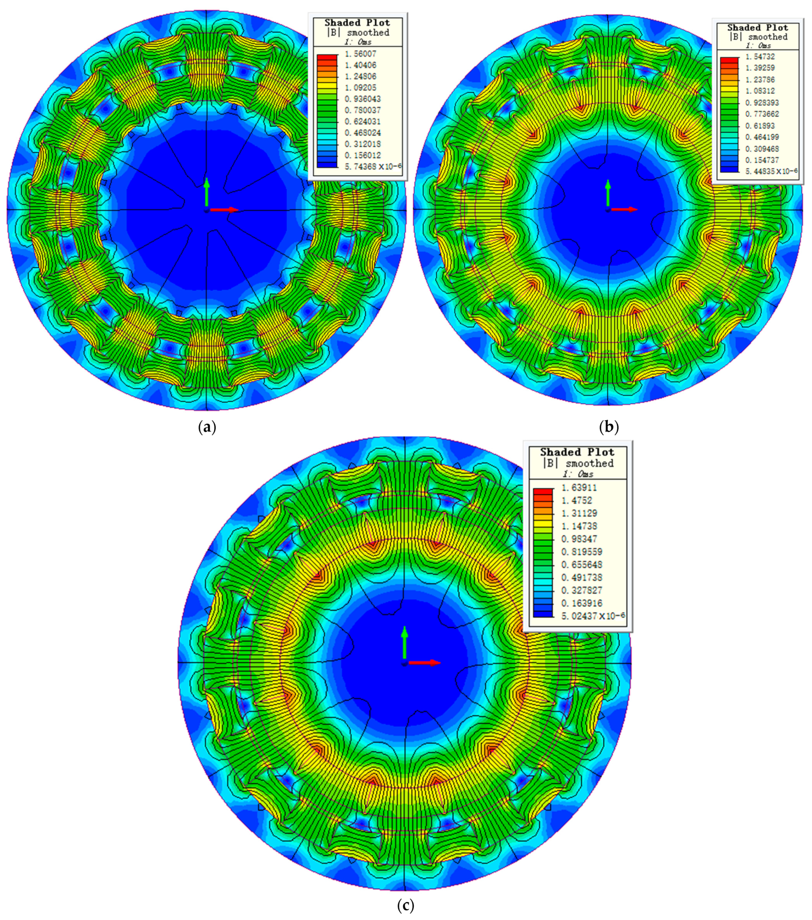
The FEA models of three types of HPMCs corresponding to L a = 50 mm are established to calculate the transmitted torque and compare with the analytical results. All of the FEA simulations are carried out using electromagnetic field analysis software Infolytica/MagNet. Figure 5a–c shows the FEA models and distribution of the HPMCs. 
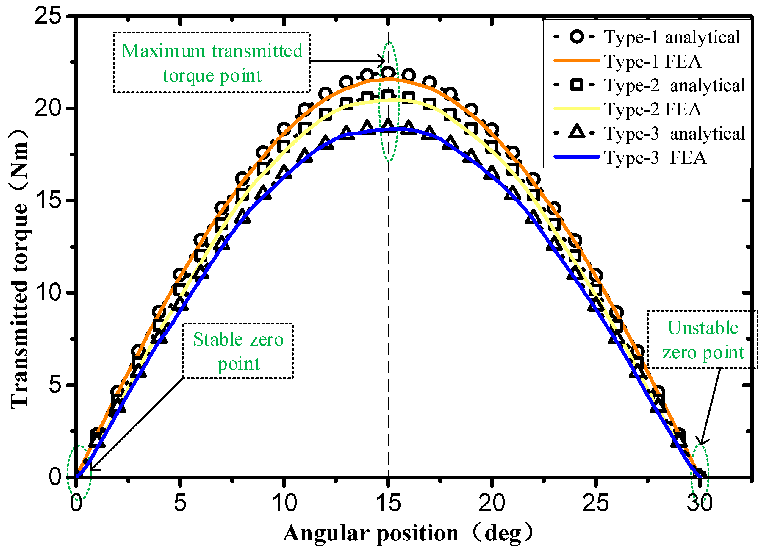
Figure 6 shows the comparison of analytical results and FEA results for the transmitted torque of initial H-HPMCs, P-HPMCs, and R-HPMCs models. The transmitted torque increases first and then decreases as the angular displacement δ increases. When δ = π / 2 p , there is maximum transmitted torque T max . It can be seen that the analytical results are in good agreement with the 2D-FEA results. Therefore, the proposed analytical method can be used for a comparative study of the three types of HPMCs.

3.3. Optimal Type Selection Method of C-HPMC

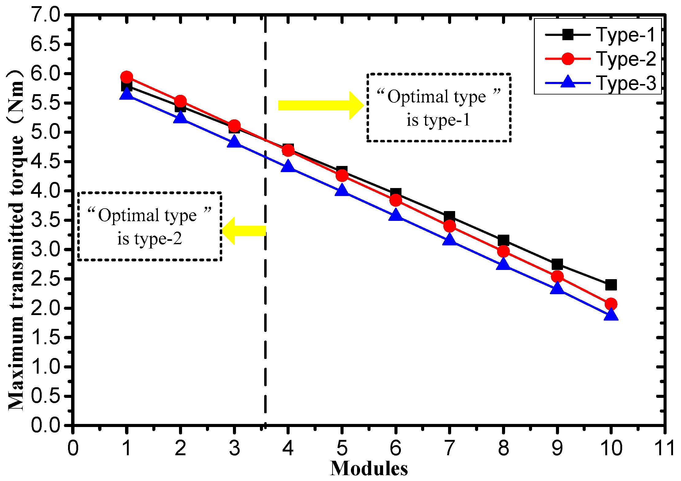
Assuming that the C-HPMC is divided into 10 modules and each module has the same axial length, the outer diameter of each module can be calculated by Formula (2) given in Section 2. Keeping other parameters such as PMs thickness and outer yoke thickness and pole pair number unchanged, the model of each module of C-HPMC can be determined, and the T max of each module is listed in Table 3. It can be seen intuitively from Figure 7 that the optimal type of each module of C-HPMC is different. In order to obtain the optimal transmitted torque, different modules of C-HPMC need to select different types of cylindrical HPMC, which we call the optimal type selection method in this paper. The T max of the C-HPMCs based on one type of HPMCs or the optimal type selection method are listed in Table 4. Obviously, the optimal type selection method is beneficial for improving the torque performance of the C-HPMC.

3.4. Axial Force of the C-HPMC

For underwater propulsion, the angular contact ball bearings or water-lubricated bearings are usually applied to balance the thrust of the propeller. Axial force is one of the main causes of problems such as bearing wear, low efficiency, and increased shaft noise. As long as there is an axial displacement between the inner and outer rotors of the HPMC, it can be a passive axial bearing to maintain the propeller in its axial position, compensating the axial force related to thrust. The advantages of passive bearings include structural simplicity, high reliability, and insignificant energy consumption, since they do not require control electronics or power sources. Calculating the axial force of the C-HPMC with an axial displacement can expand its function and application range.
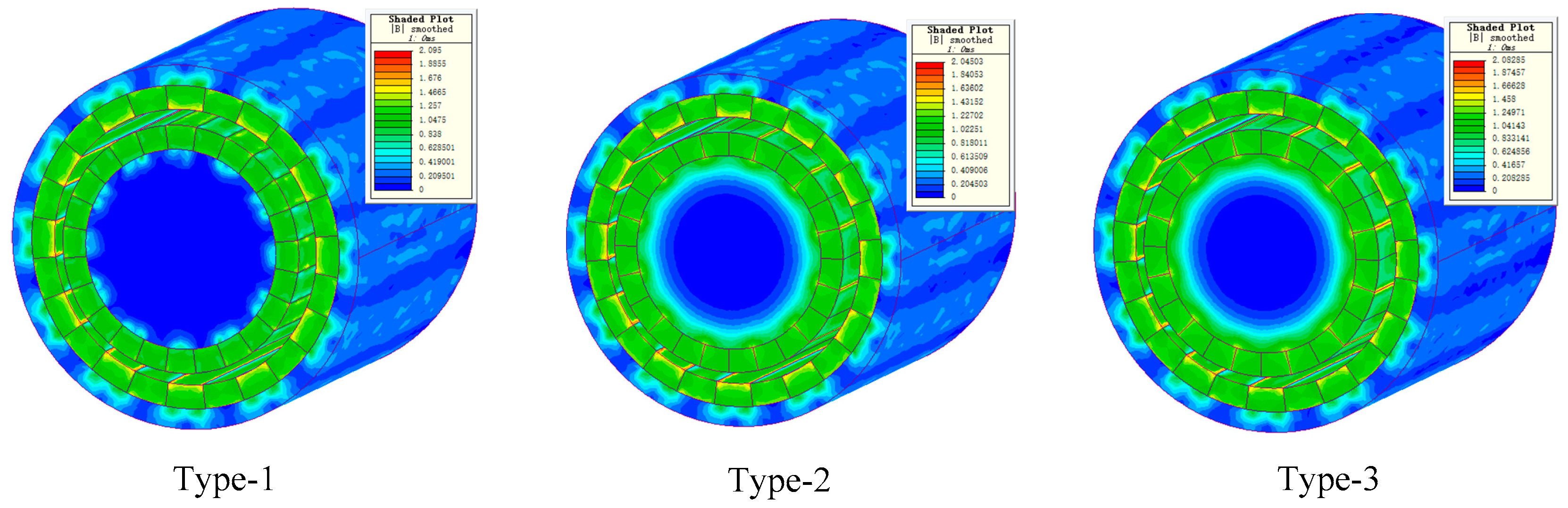
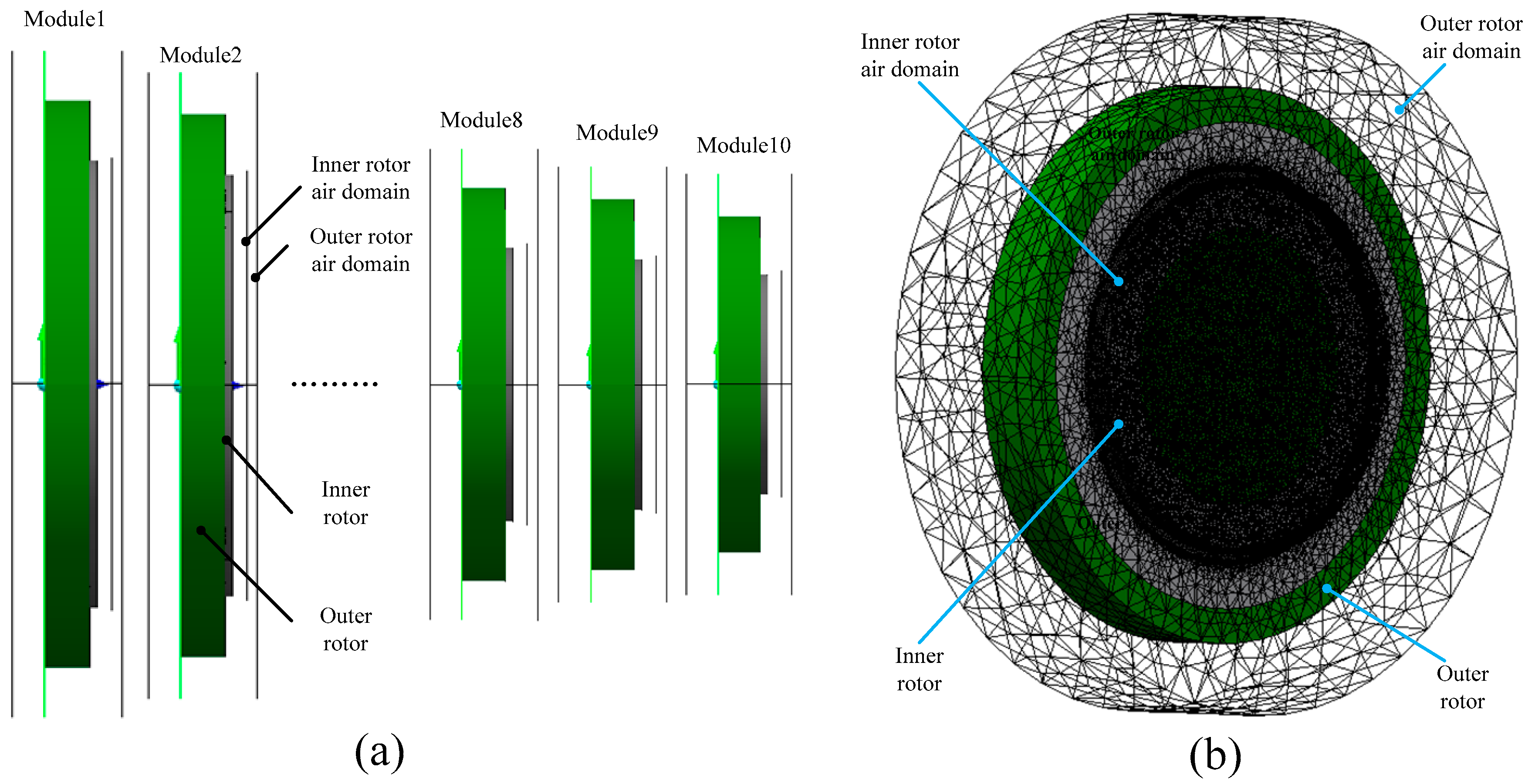
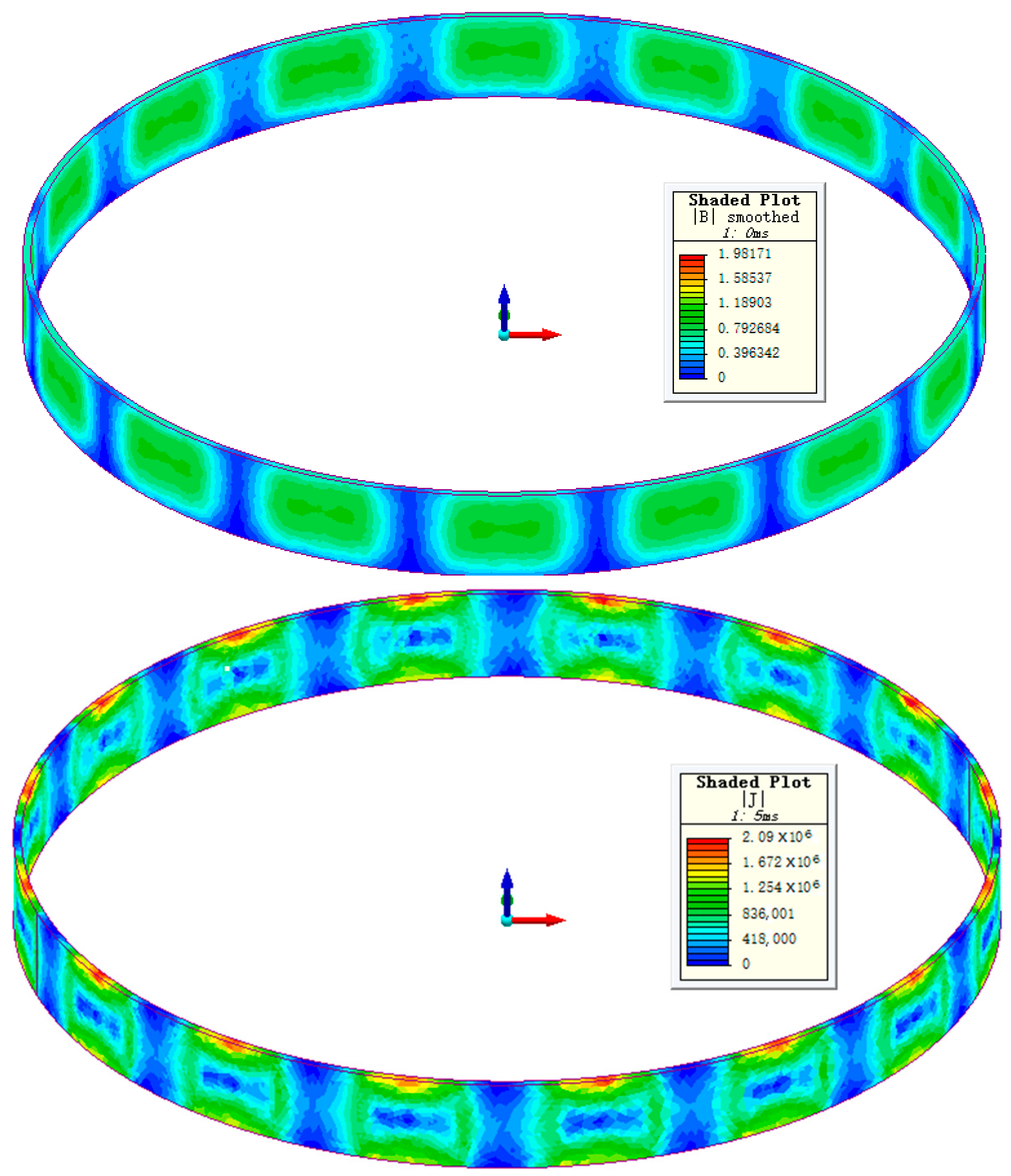
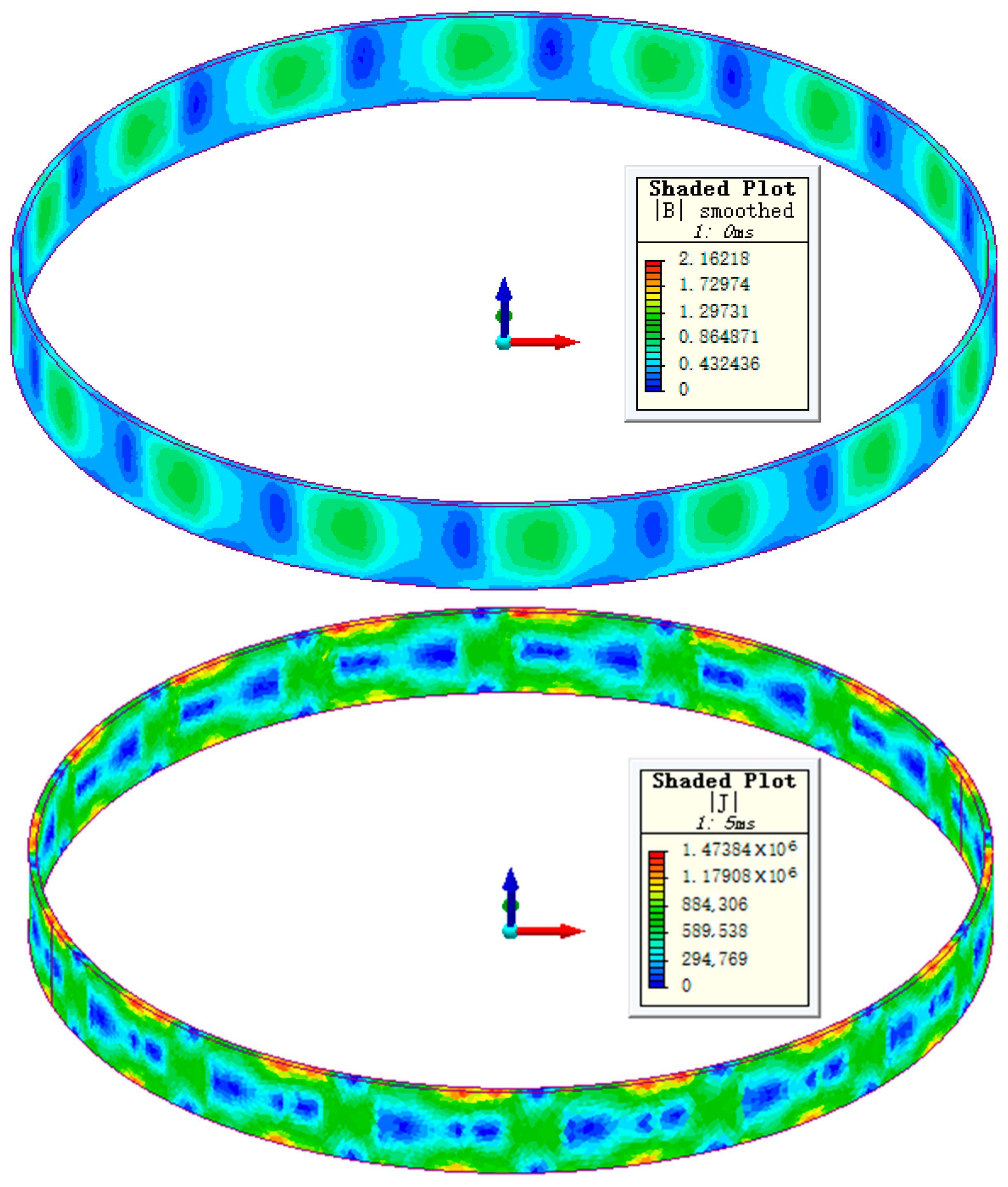
The three-dimensional (3D) FEA method is usually employed to calculate the axial force of magnetic machines. By establishing a suitable finite element analysis model, the axial force of HPMCs can be calculated accurately. Based on the parameters of the 2D FEA models in Section 3.2, 3D FEA models are established (as shown in Figure 8). The results are given in 
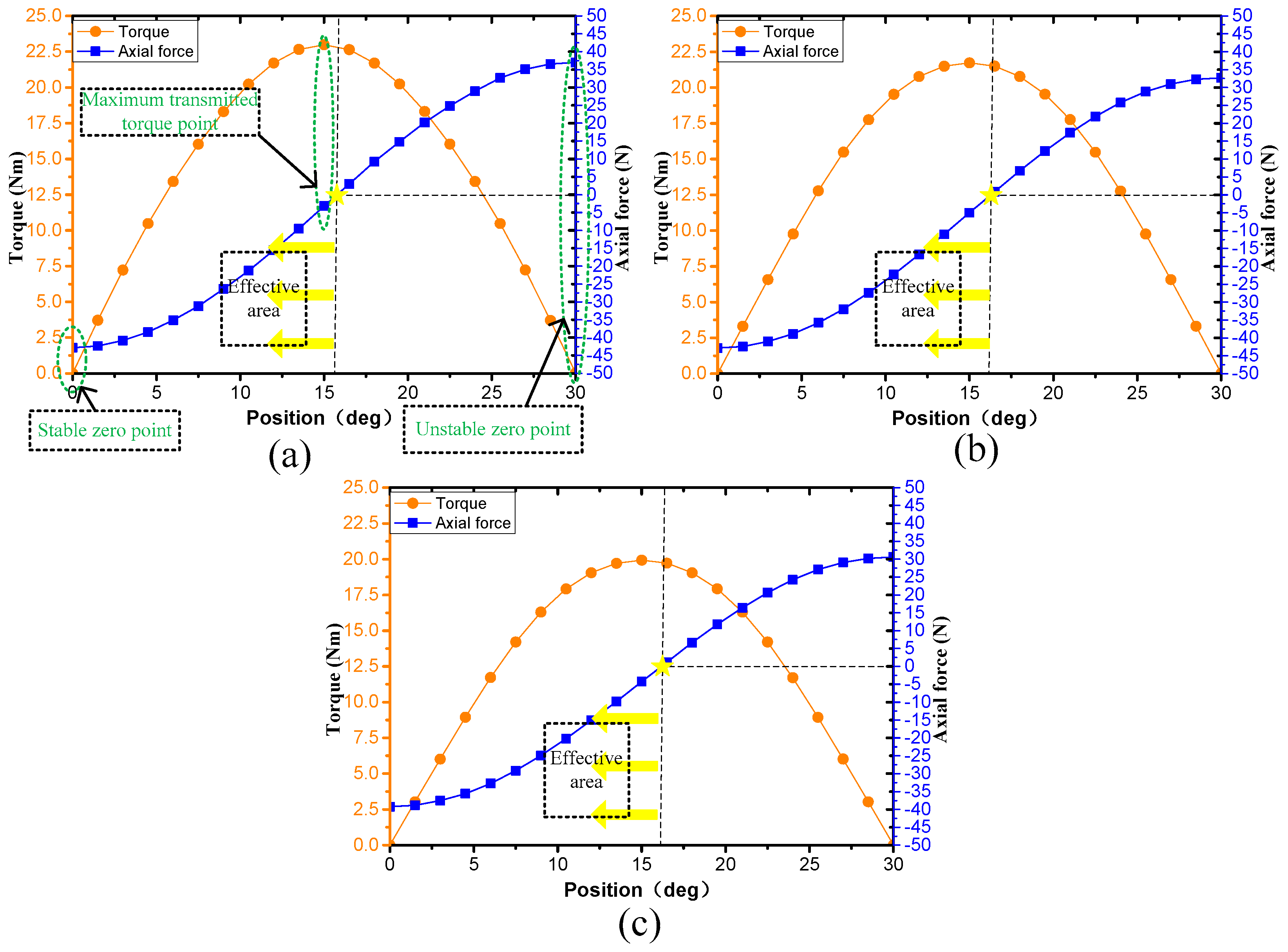
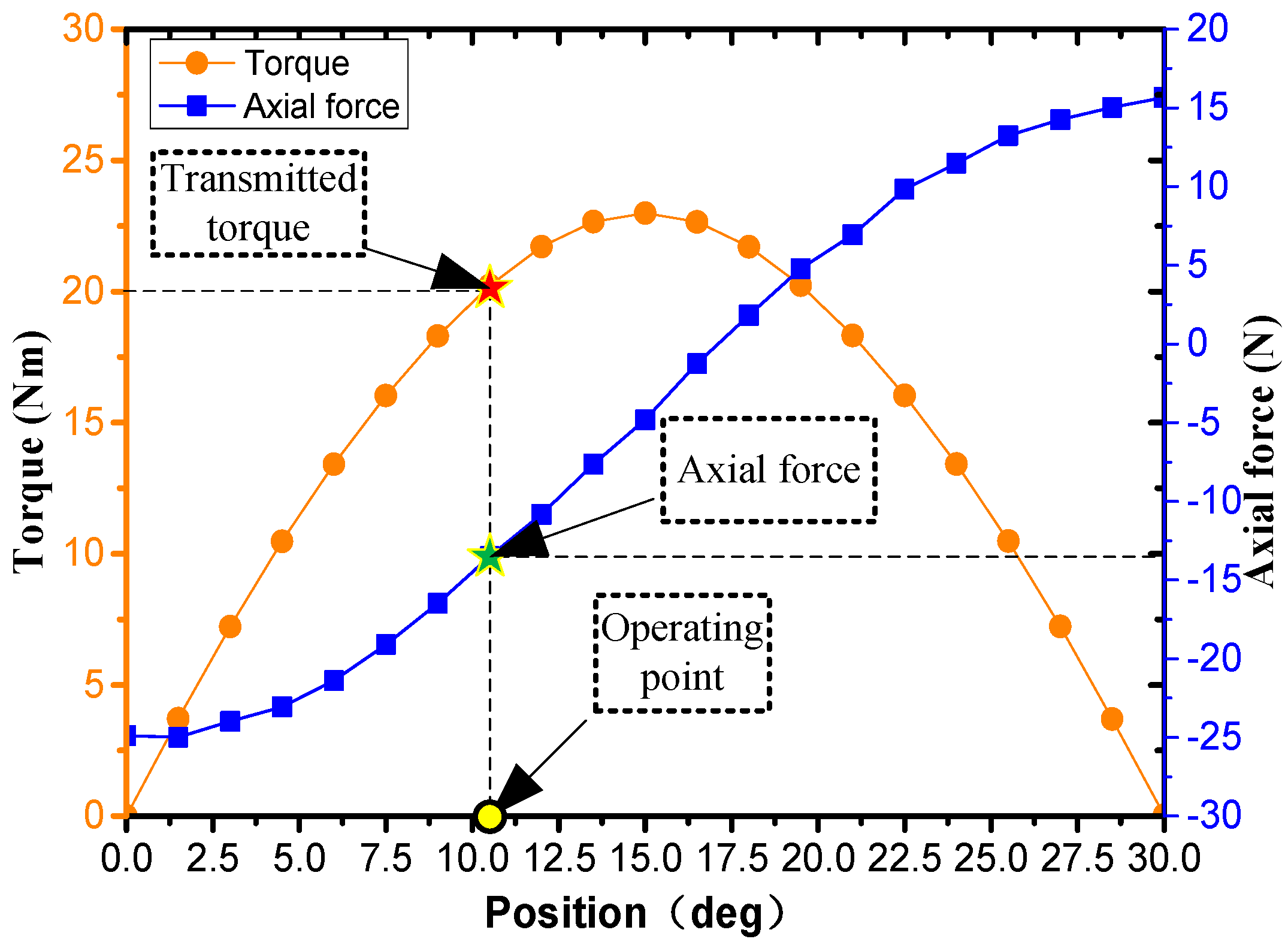
Figure 9 for the three types of HPMCs with 2 mm axial displacements. In the stable zero point, the transmitted torque is 0 and the reverse axial force is the largest. With the increase of the position angle, the transmitted torque first increases and then decreases, the axial force gradually decreases to zero and then increases in the opposite direction. The area indicated by the yellow arrow in Figure 9 is the effective working area, in which the axial force direction is opposite to the displacement direction of the inner rotor. The reverse axial force can compensate the axial force related to thrust. In 
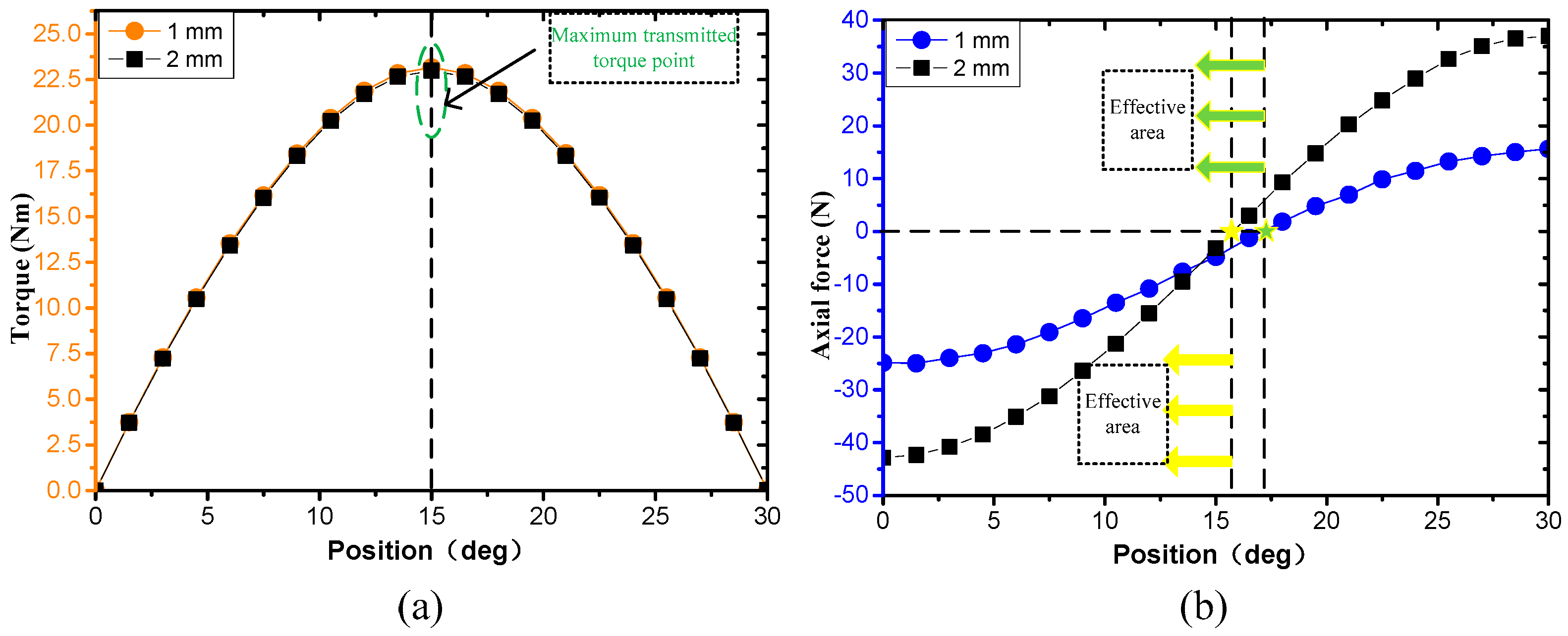
Figure 10, the transmitted torque and axial force of type-1 HPMC are compared when the axial displacement is 1 mm and 2 mm, respectively. It can be seen that as the axial displacement increases, the axial force increases rapidly, the torque decreases slightly, and the effective working area decreases. Therefore, for the C-HPMCs used in underwater propulsion, increasing the axial displacement is an effective way to compensate the propeller thrust, since the small displacement has little effect on the torque performance.

4. Design of the C-HPMC for Underwater Propulsion

4.1. Design Constraints of the C-HPMC for Underwater Propulsion

There is an isolation hood between the inner rotor and outer rotor of the C-HPMC. The isolation hood needs to be able to withstand sea water pressure. Considering the tress and processing performance, it is determined that the thickness of the isolation hood is 0.6 mm, the air gap length is 2 mm, and the thickness of the retaining ring for PMs is 0.3 mm.
For propeller, its input power P i n and output mechanical power P o u t can be expressed as:
P i n = T ω
P o u t = F V a
where T is the torque of the input shaft, ω is the rotating speed, F is the thrust of propeller, V a is the freestream fluid velocity. The efficiency of propeller η can be calculated by the equation below:
η = P o u t P i n = F V a T ω
η mainly depends on the advance ratio ( J = V a / n D ), thrust F , and the design parameters of the propeller. According to the propeller performance curve and the motion state of the underwater vehicle, the torque and thrust of the propeller near the operating point can be estimated. The overall dimensions of C-HPMC can be determined according to the geometrical constraints of tail conical space mentioned in Table 1 in Section 2. The sizing constraints and performance requirements of the C-HPMC for underwater propulsion are listed in Table 5. Next, the specific design and optimization process is introduced based on the initial model, and the significance of the new structure proposed is explained.

4.2. Selection of the Type of HPMCs and the Number of Pole Pairs

After determining the number of modules, the size and torque performance of each module can be obtained by an analytical method. For the study case, it can be seen from Figure 7 that module 1, module 2, and module 3 determine the structure of type-2 HPMCs, and the other modules determine the structure of type-1 HPMCs.
Keeping other parameters constant, when the number of the pole pairs is varied from 4 to 8 with 1 interval, the maximum transmitted torque T max of each module with different pole pairs is obtained by the analytical method above presented, as listed in Table 6. It can be seen that the pole pair number has great influence on the torque performance on the HPMCs. Increasing the number of pole pairs or using different pole pairs for different modules may continue to improve torque performance, but it is not cost effective from the perspective of permanent magnet processing costs. For the C-HPMC in this paper, we choose the pole pairs number of 8.

4.3. Axial Force and Operating Point of the C-HPMC

The axial displacement is set to 1 mm. A 3D-FEA model is established for each module to calculate the total axial force of the C-HPMC. The 3D-FEA models for the calculation of the C-HPMC are shown in Figure 11. Figure 11a shows the 3D-FEA models for 10 modules, and Figure 11b shows the mesh of the calculation model. The total axial force of the C-HPMC is the total of the axial forces of each module. Figure 12 shows the total axial force and transmitted torque of the C-HPMC with 1 mm axial displacement. According to the rated torque of the propeller of underwater propulsion system, the operating point of the C-HPMC can be obtained, and the corresponding axial force is about 180N. This means that most of the axial force of the propeller can be compensated by the C-HPMC. At the same time, determining the operating point is very important for calculating the eddy current loss and efficiency. Compared with the axial force and transmitted torque of the traditional cylindrical HPMCs with 1 mm axial displacement (as shown in Figure 13). The maximum transmitted torque and maximum axial force of the C-HPMC and traditional cylindrical HPMCs are listed in Table 7. It can be found that the C-HPMC has better torque and axial force performance.

4.4. Eddy Current Loss of the C-HPMC

When the C-HPMC is working normally, the metallic isolation cover placed in the rotating magnetic field will induce a strong and distributive eddy current. The eddy current loss of isolation cover is the main factor affecting the efficiency of C-HPMCs. Figure 14 and Figure 15 are the flux density and eddy current distribution on the isolation cover of module 1 at a stable zero point and operating point, respectively. The flux density and current distribution of the isolation cover are quite different under different angular position. This means that the loss of the C-HPMC is related to the working state, so determining the operating point is a prerequisite for evaluating performance. Ignoring the interaction between modules, the eddy current loss on the isolation cover of each module at the operating point is calculated. At the rated speed, the total eddy current loss of C-HPMC is 0.96 W.
The aim of this paper is to make full use of the tail space to meet the requirement of non-contact torque transmission, using the axial displacement of the magnetic coupling to compensate the axial force generated by the propeller at the same time. The flowchart of the design method of the C-HPMC combining analytical method and FEA method is shown in Figure 16. The analytical method is used for the initial design, design parameter analysis, and establishment of optimization models. The FEA method is used to analyze the performance of the optimal model of C-HPMC at the operating point.
The design method presented in this paper lays the foundation for the application of the C-HPMC in the underwater propulsion system. The design of the C-HPMC is a process of continuous iteration and optimization. In engineering applications, it is hoped that the torque generated by each unit of PMs is the largest, since permanent magnets are relatively expensive. In theory, the more modules, the better, but through 3D-FEA calculations, it can be found that when the number of modules is too large, the magnetic flux leakage at the end of each module will be severe, which will result in a significant decrease in torque performance. Therefore, the optimal design of the C-HPMC will be a multi-objective optimization problem, which needs further research.

5. Conclusions

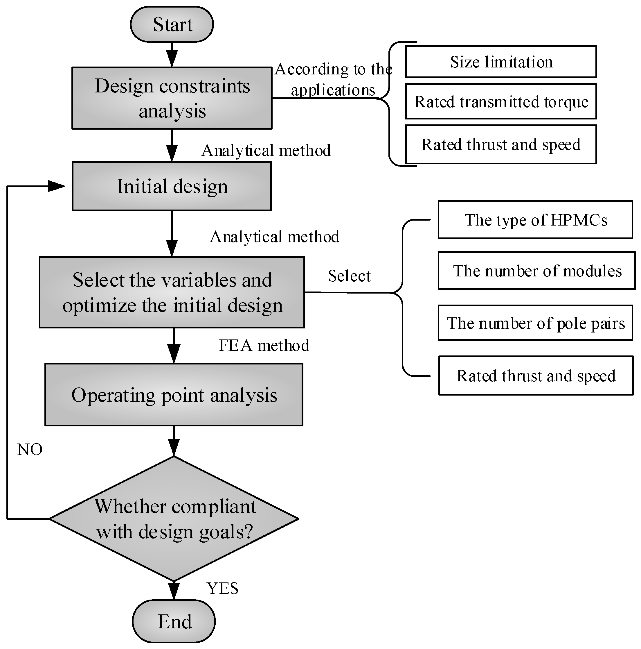
A novel C-HPMC is proposed and analyzed in this paper, which combines multiple cylindrical HPMCs with different sizes into an approximately conical structure. The C-HPMC adopts two methods to improve the torque transmission capacity of the propulsion system: one is the multi-module specially shaped structure, and the other is the use of the Halbach array PMs. In order to obtain the optimal transmitted torque, different modules of C-HPMC need to select different types of cylindrical HPMC. Three common HPMCs are comparatively analyzed by analytical method, and the “optimal type selection” method for the design of C-HPMC is proposed. Then, the axial forces of three types of HPMCs with axial displacement are calculated by the 3D-FEA method. The flowchart of the design of the novel C-HPMC is described, and a prototype is designed. Compared with the traditional cylindrical HPMCs, the axial force of the novel C-HPMC can compensate most of the thrust generated by the propeller while transmitting torque, which is very helpful to extend the life of the bearing and increase the reliability. Further work will focus on the multi-level and multi-disciplinary optimization of the overall performance of C-HPMCs. Based on the research mentioned above, the design framework of the C-HPMC can be extended to a variety of specially shaped complex magnetic machines, so that the performance of the magnetic machine can be well expanded.

Author Contributions

Y.L., Y.H. and Y.G. conceived the study and established the analytical method; Y.H. and Z.M. analyzed the analytical results; Y.L. wrote the manuscript; Y.G. and B.S. reviewed and edited the manuscript. All authors have read and agreed to the published version of the manuscript.

Funding

This research was funded by [the National Science Foundation of China] Grant number [51179159, 61572404] and the APC was funded by [the Shaanxi Province Youth Science and Technology New Star Project].

Institutional Review Board Statement

Not applicable.

Informed Consent Statement

Not applicable.

Data Availability Statement

Not applicable.

Acknowledgments

This research was supported by the National Science Foundation of China (Grant No. 51179159, 61572404) and the Shaanxi Province Youth Science and Technology New Star Project (Grant No.2016KJXX-57).

Conflicts of Interest

The authors declare no conflict of interest.

References

  1. Macreadie, P.I.; McLean, D.L.; Thomson, P.G.; Partridge, J.C.; Jones, D.O.B.; Gates, A.R.; Benfield, M.C.; Collin, S.P.; Booth, D.J.; Smith, L.L.; et al. Eyes in the sea: Unlocking the mysteries of the ocean using industrial, remotely operated vehicles (ROVs). Sci. Total Environ. 2018, 634, 1077–1091. [Google Scholar] [CrossRef] [Green Version]
  2. Petillot, Y.R.; Antonelli, G.; Casalino, G.; Ferreira, F. Underwater Robots: From Remotely Operated Vehicles to Intervention-Autonomous Underwater Vehicles. IEEE Robot. Autom. Mag. 2019, 26, 94–101. [Google Scholar] [CrossRef]
  3. Byron, J.; Tyce, R. Designing a vertical/horizontal AUV for deep ocean sampling. In Proceedings of the OCEANS 2007, Vancouver, BC, Canada, 29 September–4 October 2007; pp. 1–10. [Google Scholar]
  4. Charpentier, J.F.; Fadli, N.; Jennane, J. Study of ironless permanent magnet devices being both a coupling and an axial bearing for naval propulsion. IEEE Trans. Magn. 2003, 39, 3235–3237. [Google Scholar] [CrossRef]
  5. Potgieter, J.H.J.; Kamper, M.J. Optimum design and comparison of slip permanent-magnet couplings with wind energy as case study application. IEEE Trans. Ind. Appl. 2014, 50, 3223–3234. [Google Scholar] [CrossRef]
  6. Yonnset, J.P.; Hemmerlin, S.; Rulliere, E.; Lemarquand, G. Analytical calculation of permanent magnet couplings. IEEE Trans. Magn. 1993, 29, 2932–2934. [Google Scholar] [CrossRef]
  7. Cheng, B.; Pan, G. Analysis and structure optimization of radial halbach permanent magnet couplings for deep sea robots. Math. Probl. Eng. 2018, 2018, 1–11. [Google Scholar] [CrossRef]
  8. Dolisy, B.; Mezani, S.; Lubin, T.; Leveque, J. A new analytical torque formula for axial field permanent magnets coupling. IEEE Trans. Energy Convers. 2015, 30, 892–899. [Google Scholar] [CrossRef] [Green Version]
  9. Nagrial, M.H. Design optimization of magnetic couplings using high energy magnets. Electr. Mach. Power Syst. 1993, 21, 115–126. [Google Scholar] [CrossRef]
  10. Charpentier, J.F.; Lemarquand, G. Optimal design of cylindrical air-gap synchronous permanent magnet couplings. IEEE Trans. Magn. 1999, 35, 1037–1046. [Google Scholar] [CrossRef]
  11. Ravaud, R.; Lemarquand, V.; Lemarquand, G. Analytical design of permanent magnet radial couplings. IEEE Trans. Magn. 2010, 46, 3860–3865. [Google Scholar] [CrossRef]
  12. 1Lubin, T.; Mezani, S.; Rezzoug, A. Simple analytical expressions for the force and torque of axial magnetic couplings. IEEE Trans. Energy Convers. 2012, 27, 536–546. [Google Scholar]
  13. Hornreich, R.M.; Shtrikman, S. Optimal design of synchronous torque couplers. IEEE Trans. Magn. 1978, 14, 800–802. [Google Scholar] [CrossRef]
  14. Ferreira, C.; Vaidya, J. Torque analysis of permanent magnet coupling using 2d and 3d finite elements methods. IEEE Trans. Magn. 1989, 25, 3080–3082. [Google Scholar] [CrossRef]
  15. Wu, W.; Lovatt, H.C.; Dunlop, J.B. Analysis and design optimisation of magnetic couplings using 3D finite element modelling. IEEE Trans. Magn. 1997, 33, 4083–4085. [Google Scholar] [CrossRef]
  16. Eliès, P.; Lemarquand, G. Analytical optimization of the torque of a permanent-magnet coaxial synchronous coupling. IEEE Trans. Magn. 1998, 34, 2267–2273. [Google Scholar] [CrossRef]
  17. Charpentier, J.F.; Lemarquand, G. Optimization of unconventional P.M. couplings. IEEE Trans. Magn. 2002, 38, 1093–1096. [Google Scholar] [CrossRef]
  18. Mallinson, J.C. One-Sided Fluxes—A Magnetic Curiosity? IEEE Trans. Magn. 1973, 9, 678–682. [Google Scholar] [CrossRef] [Green Version]
  19. Halbach, K. Design of permanent multipole magnets with oriented rare earth cobalt material. Nucl. Instrum. Methods 1980, 169, 1–10. [Google Scholar] [CrossRef] [Green Version]
  20. Zhu, Z.Q.; Howe, D. Halbach permanent magnet machines and applications: A review. IEE Proc. Electr. Power Appl. 2001, 148, 299–308. [Google Scholar] [CrossRef]
  21. Xia, Z.P.; Zhu, Z.Q.; Howe, D. Analytical magnetic field analysis of halbach magnetized permanent-magnet machines. IEEE Trans. Magn. 2004, 40, 1864–1872. [Google Scholar] [CrossRef]
  22. Zhu, Z.Q. Recent development of Halbach permanent magnet machines and applications. In Proceedings of the 2007 Power Conversion Conference—Nagoya, Nagoya, Japan, 2–5 April 2007. [Google Scholar]
  23. Bird, J.; Li, K.; Kadel, J.; Wright, J.; Som, D.; Williams, W. Analysis and testing of a hybrid Halbach magnetic gearbox. In Proceedings of the 2017 IEEE International Magnetics Conference, Dublin, Ireland, 24–28 April 2017; Volume 53, pp. 11–16. [Google Scholar]
  24. Jing, L.; Huang, Z.; Chen, J.; Qu, R. An Asymmetric Pole Coaxial Magnetic Gear with Unequal Halbach Arrays and Spoke Structure. IEEE Trans. Appl. Supercond. 2019, 30, 1–5. [Google Scholar] [CrossRef]
  25. Jing, L.; Gong, J.; Chen, J.; Huang, Z.; Qu, R. A Novel Coaxial Magnetic Gear With Unequal Halbach Arrays and Non-Uniform Air Gap. IEEE Trans. Appl. Supercond. 2020, 30, 1–5. [Google Scholar] [CrossRef]
  26. Yuan, D.; Li, J.; He, Y.; Zhang, H. Characteristic analysis of transmission torque of magnetic coupling with Halbach array. J. Magn. Mater. Devices 2011, 42, 36–40. [Google Scholar]
  27. Li, K.; Bird, J.Z.; Acharya, V.M. Ideal radial permanent magnet coupling torque density analysis. IEEE Trans. Magn. 2017, 53, 2–5. [Google Scholar] [CrossRef]
  28. Kang, H.B.; Choi, J.Y.; Cho, H.W.; Kim, J.H. Comparative study of torque analysis for synchronous permanent magnet coupling with parallel and halbach magnetized magnets based on analytical field calculations. IEEE Trans. Magn. 2014, 50, 3–6. [Google Scholar] [CrossRef]
  29. Seo, S.W.; Kim, Y.H.; Lee, J.H.; Choi, J.Y. Analytical torque calculation and experimental verification of synchronous permanent magnet couplings with Halbach arrays. AIP Adv. 2018, 8, 056609. [Google Scholar] [CrossRef]
  30. Li, Y.; Hu, Y.; Song, B.; Mao, Z.; Tian, W. Performance analysis of conical permanent magnet couplings for underwater propulsion. J. Mar. Sci. Eng. 2019, 7, 187. [Google Scholar] [CrossRef] [Green Version]
Figure 1. Underwater vehicle and propulsion unit. (a) Tail segment. (b) Radial permanent magnet coupling (PMC). (c) Novel conical Halbach permanent magnet coupling (C-HPMC).
Jmse 09 00290 g001
Figure 2. PMCs for underwater propulsion. (a) Structure of traditional cylindrical PMC. (b) Structure of the novel C-HPMC.
Jmse 09 00290 g002
Figure 3. Structure of three common HPMCs. (a) Type-1 (Halbach magnetized inner rotor). (b) Type-2 (parallel magnetized inner rotor). (c) Type-3 (radial magnetized inner rotor).
Jmse 09 00290 g003
Figure 4. Waveforms of magnetization components M r and M θ . (a) Halbach magnetized outer rotor. (b) Halbach magnetized inner rotor. (c) Parallel magnetized inner rotor. (d) Radial magnetized inner rotor.
Jmse 09 00290 g004
Figure 5. Finite element analysis (FEA) models and flux distributions of HPMCs. (a) Type-1, (b) Type-2, and (c) Type-3.
Jmse 09 00290 g005
Figure 6. Comparison of analytical results and FEA results for transmitted torque of three HPMCs.
Jmse 09 00290 g006
Figure 7. T max of each module of C-HPMC.
Jmse 09 00290 g007
Figure 8. 3D-FEA models of three types of HPMCs with 2 mm axial displacement.
Jmse 09 00290 g008
Figure 9. Axial force and transmitted torque of three types of HPMCs with 2 mm axial displacement. (a) Type-1, (b) Type-2, and (c) Type-3.
Jmse 09 00290 g009
Figure 10. Influence of different axial displacements. (a) Torque and (b) Axial force.
Jmse 09 00290 g010
Figure 11. 3D-FEA models for axial force calculation of the C-HPMC (a) 3D-FEA models for 10 modules (b) mesh of calculation model.
Jmse 09 00290 g011
Figure 12. Axial force and transmitted torque of the C-HPMC with 1 mm axial displacement.
Jmse 09 00290 g012
Figure 13. Axial force and transmitted torque of the traditional cylindrical HPMC with 1 mm axial displacement.
Jmse 09 00290 g013
Figure 14. Flux density and eddy current distribution on isolation cover of module 1 at stable zero point.
Jmse 09 00290 g014
Figure 15. Flux density and eddy current distribution on isolation cover of module 1 at operating point.
Jmse 09 00290 g015
Figure 16. Flowchart of the design of C-HPMCs for underwater propulsion.
Jmse 09 00290 g016
Table 1. Geometrical parameters of the tail conical space and the initially designed C-HPMC.
Design ParametersValue
Front end diameter D s 80 mm
Axial length L s 60 mm
Half-cone angle α 15°
Outer rotor yoke thickness3 mm
Outer PM thickness3.5 mm
Air gap length2 mm
Inner PM thickness3.5 mm
Pole pairs p 6
Number of modules N 10
Table 2. T max of three types of cylindrical HPMCs with different sizes.
L a / mm D a / mm T max   of   HPMCs / Nm
Type-1Type-2Type-3
3063.9221.6621.3219.93
3561.2423.4122.7921.21
4058.5624.6023.6521.91
4555.8825.2023.9022.03
5053.2125.2123.5521.59
5550.5324.6322.6120.62
6047.8523.4421.1419.14
Table 3. T max of each module of C-HPMC.
Modules D a n / mm T max of C-HPMC/Nm
Type-1 HPMCType-2 HPMCType-3 HPMC
176.785.79295.93995.6349
273.575.43685.52795.2273
370.355.0755.11134.8163
467.144.70694.69014.4021
563.924.33184.26453.9851
660.713.94923.8353.5663
757.493.55863.40273.147
854.283.16022.96952.7295
951.062.75482.53842.317
1047.852.34452.07031.8699
Table 4. T max of C-HPMC based on “optimal type selection” method.
Magnetization Type of HPMC T max / Nm
C-HPMCType-141.1107
Type-240.3496
Type-337.6954
optimal type selection41.3851
Table 5. Sizing constraints and performance requirements of the C-HPMC for underwater propulsion.
ItemsValue
Air gap length2 mm
Thickness of isolation hood0.5 mm
Thickness of retaining ring0.25 mm
Material of isolation hood and retaining ring304 stainless steel
Rated torque of propeller20 Nm
Rated thrust of propeller200 N
Rated speed600 rpm
Material of PMsNd-Fe-B
Residual magnetic flux density of PMs B r 1.27 T
Relative permeability of PMs1.1045
Table 6. T max of each module with different pole pairs.
T max
(Unit: Nm)
Pole Pairs Number
45678
Modules14.26525.17345.93996.55267.0108
24.01274.84365.52796.05676.4336
33.75814.51025.11135.55675.8545
43.31114.06284.70695.22835.622
53.08883.76744.33184.77015.0818
62.86333.46633.94924.30424.5359
72.63373.15863.55863.83143.9869
82.39922.84373.16023.35323.4382
92.15892.52082.75482.87272.8949
101.91172.192.34452.39442.3644
Table 7. Comparison between the C-HPMC and traditional cylindrical HPMC.
Type of the DesignC-HPMCCylindrical HPMC
Maximum transmitted torque (Nm)39.216622.9909
Maximum axial force (N)247.793824.8809
Publisher’s Note: MDPI stays neutral with regard to jurisdictional claims in published maps and institutional affiliations.

