
Effectiveness of Floating Breakwater in Special Configurations for Protecting Nearshore Infrastructures


1
Technology Center of Offshore and Marine, Singapore, No. 12, Prince George’s Park, #04-01, Singapore 118411, Singapore
2
Department of Civil and Environmental Engineering, National University of Singapore, 1 Engineering Drive 2, Block E1A #07-03, Singapore 117576, Singapore
*
Author to whom correspondence should be addressed.
J. Mar. Sci. Eng. 2021, 9(7), 785; https://0-doi-org.brum.beds.ac.uk/10.3390/jmse9070785
Submission received: 31 May 2021
/
Revised: 16 July 2021
/
Accepted: 17 July 2021
/
Published: 20 July 2021
(This article belongs to the Special Issue Recent Advances in Floating Structures)
Abstract
:This paper investigates the effectiveness of floating breakwaters consisting of two barges (L-shape), three barges (U-shape), four barges (barge frame), and conventional single floating breakwater. The floating breakwaters of different spatial layouts have sheltered internal gaps/moonpools when compared to their conventional counterparts. The motions of these floating breakwaters and their effectiveness in wave transmission and motion reduction of the protected floating bodies are evaluated. The study is conducted based on a subsystem of a floating hydrocarbon storage facility that combines a floating breakwater with two floating tanks, studied previously. Numerical models based on linear potential flow theory are built for these floating breakwaters with and without the floating tanks. The numerical models of the barge frame are validated through laboratory experiments, and the dipole damping lids to reduce the resonant fluid motions in the gaps/moonpools are calibrated with experimental results. The L-shape floating breakwater is found effective in reducing wave transmissions without the presence of the floating tanks, while the barge frame is the most effective in the motion reduction of the floating tanks. In addition, significant fluid resonant motions are identified for all investigated floating breakwaters, including the conventional one. Orienting the structure obliquely can improve the performance of the floating breakwaters of special configurations, especially the barge frame. The results and findings show the importance of considering the protected floating structures in the analysis when designing floating breakwaters for many types of marine structures, including floating fish farms and floating cities in coastal waters.
1. Introduction
Climate change has led to sea level rise over the past decades. Sea level rise may threaten the coastal region of many countries, such as Singapore. Moreover, the fast development of human activity and urbanization in these countries also increases the demand for land resources. When facing these challenges, sea space utilization through the development of coastal floating structures becomes one potential solution. In recent years, a few innovative floating structures, such as floating solar farms [1] and floating cities [2,3], have been developed or proposed. These floating structures can not only supply renewable energy and seafood, but also create infrastructures for human activities on the sea. To support mankind’s activities, these floating facilities must be affordable, sustainable, and reliable. To achieve this goal, it is critical to protect the floating facilities with reduced environmental actions. Breakwater is one of the engineering solutions which can reduce the wave actions in the protected water.
Breakwaters can either be bottom founded or self-floating and may be used to protect shoreline or marine structures. Floating breakwaters have a few advantages when compared to the bottom founded ones, such as the lower construction cost and less environmental impact [4]. One unique advantage of floating breakwaters is that the influence from tidal variation and sea level rise can be minimized. Conventional floating breakwaters can be categorized into four types: box, pontoon, mat, or tethered float, based on their shapes [5]. On top of these four categories, three more types of floating breakwaters were introduced in [6]: frame-type, horizontal-plate type, and other types. Special cross-section shapes, such as inverse T-shape [7], π-shape [8], and twin horizontal cylinders [9] were also developed. In addition, floating breakwaters can be interconnected multibody systems. The connections could be either flexible or simple articulations. Hydroelastic responses of these floating structures were investigated extensively [10,11,12]. To introduce perforated plates on floating breakwaters and combining floating breakwaters with wave energy converters were also investigated [13,14]. The floating breakwaters in many of these studies are straight-line types, and some of them further simplified the problem into a two-dimensional domain to reduce the resources for simulations or model tests.
However, in reality, the length of floating breakwaters is finite which can lead to significant three-dimensional effects. The comparison between the model test results of floating breakwaters in a 2D wave flume and 3D wave basin in [15], showed significant differences, showing the importance of considering the 3D effect. Their studies also investigated a special J-shape floating breakwater with different spatial layouts from the conventional straight floating breakwaters. It was found that the wave attenuation performance of the J-shape improves under the perpendicular wave attack, similar to the increase of wave obliquity, although the mooring load increases. An L-shape floating breakwater with one end connected to the shoreline was investigated in [16], but the focus was on the performance of the wave energy converter connected to the breakwater. In general, very few studies investigated the effectiveness of floating breakwaters under different spatial layouts.
When investigating the performance of floating breakwaters, many research works introduce wave transmission coefficient and evaluate the wave height in the sheltered water without the presence of the protected floating bodies. However, there may be hydrodynamic interactions among the floaters or multiple lines of floating breakwaters. The multiple lines of floating breakwaters were investigated in [17,18]. A similar but more theoretical problem was a cylinder in front of a vertical wall, such as in [19,20], where the wave diffractions from the cylinder were investigated, while a more complicated case where a truncated cylinder placed in front of an orthogonal breakwater was explored in [21]. These theoretical studies reveal the importance of the hydrodynamic interactions between breakwaters and floaters. However, not many studies have investigated the effectiveness of moving floating breakwaters on the motion reduction of floating bodies that are placed close to them.
The hydrodynamic interactions between floating breakwaters and the protected floaters and fluid resonant motions can be significant, which influence the motions of both floaters. Such phenomena were identified from a numerical and experimental study by the authors on a subsystem of a novel floating hydrocarbon storage facility in coastal waters [22]. The subsystem combines a special frame-like floating breakwater with two unique floating hydrocarbon storage tanks [23,24,25]. The special floating breakwater is formed by four interconnected barges with an internal moonpool. The floating tanks are placed in the moonpools close to the barges. The study has revealed the importance of hydrodynamic couplings, but the effectiveness of the barge frame on the motion reduction of the floating tanks is not well assessed. Also, it is not clear how effective the barge frame is when compared to the conventional floating breakwater and breakwaters with different spatial configurations.
In this paper, we will further investigate the research gaps through numerical studies. The effectiveness of floating breakwaters of three special configurations (including barge frame, L-shape, and U-shape), with and without the floating tanks, will be further investigated. The special configurations of floating breakwaters can be easily formed by interconnected conventional box-type floating breakwaters. The performance will be assessed using the wave transmissions, their motions, and the motions of the protected floaters. The effectiveness is also compared to the conventional box-type straight floating breakwaters. The numerical study is in addition to the case studies on the subsystem of the floating hydrocarbon storage facility, where the numerical models based on linear potential flow theory have been solidly validated by comprehensive experiments [22]. Although the results presented herein are for a specific application, the system is representative of other similar floating nearshore structures, such as floating fish farms and floating cities. Therefore, the results could be useful when designing breakwaters to protect these floating structures in coastal waters.
The remaining parts of this paper are organized as follows. Section 2 presents the problem definition, including the description of the special configurations. Section 3 briefly presents the methodology, numerical models, and validations. It is followed by discussions on the performance of the floating breakwaters of the different spatial configurations without the presence of the floating tanks in Section 4.1. Section 4.2 further investigates the effectiveness of floating breakwaters on motion reduction of the protected floating tanks. Section 5 presents the concluding remarks.
2. Problem Definition
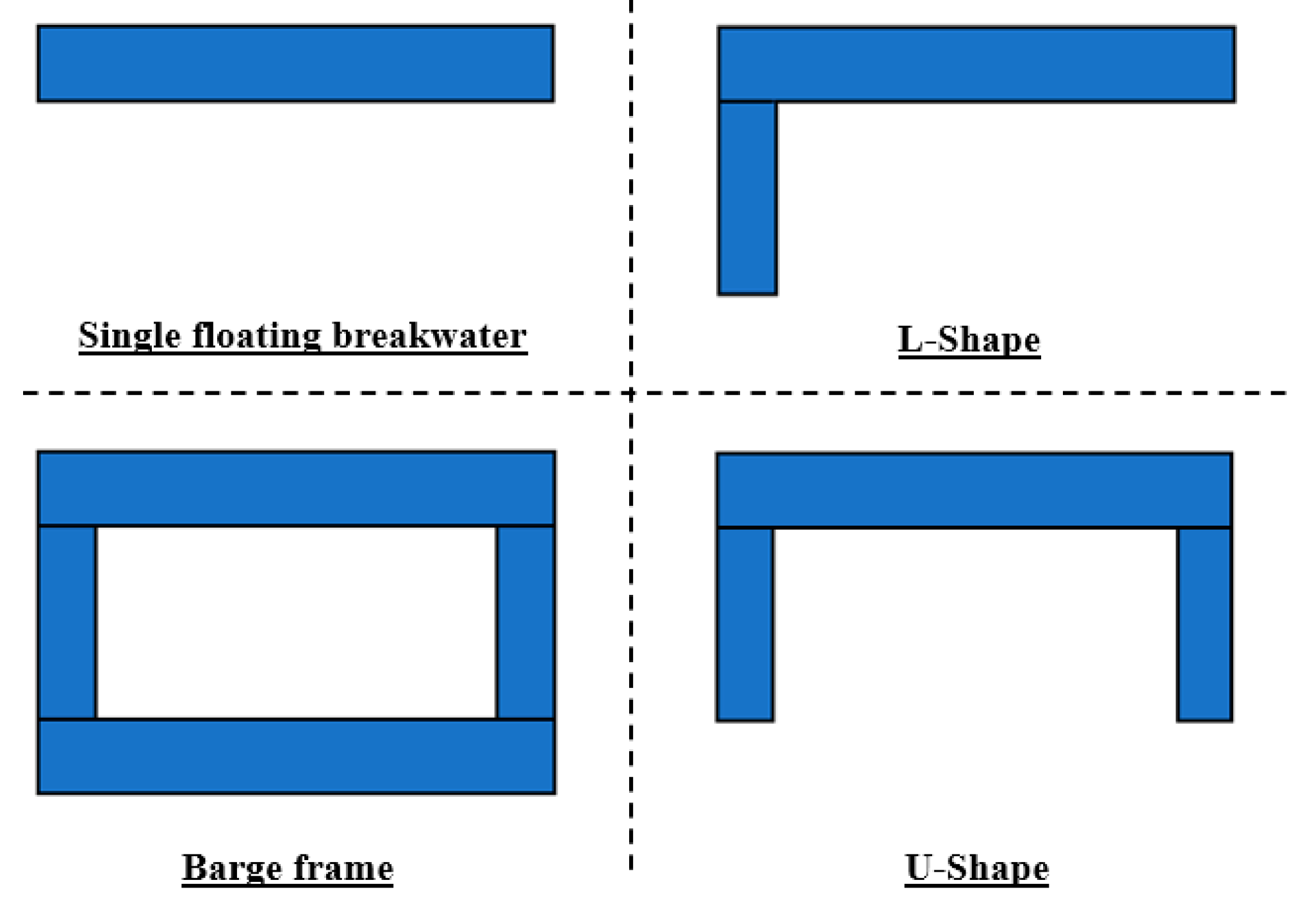
The three special configurations of floating breakwaters (L-shape, U-shape, and barge frame), together with the conventional floating breakwaters for comparison, are shown in Figure 1. As aforementioned, the barge frame is developed for the subsystem of the floating hydrocarbon storage facility. It consists of two identical longer barges and two identical shorter barges. The other configurations are simply defined by removing one to two barges.
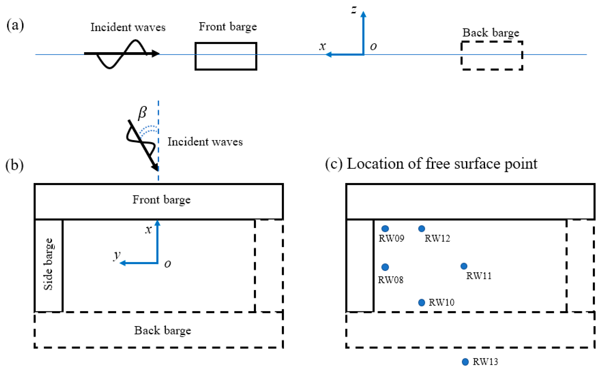
To describe the motions of the floating bodies, a global coordinate system oxyz is introduced as shown in Figure 2. The origin is located at the center of the free surface of the barge frame. The z-axis and x-axis are pointing upwards and perpendicular to the beam of the floating breakwater, respectively, with the y-axis determined by the right-hand rule. For ease of comparison, the global coordinate system remains the same for all other configurations in this paper. The definition of the incident wave angle β and the locations of free surface points, which will be used later in this paper, can also be found in Figure 2. For the case when two floating tanks are placed in the sheltered waters, the tanks are placed side-by-side in the sheltered water close to the breakwaters. The gap between the tanks and the front barge is 5 m, while the gap between the two tanks is about 11 m. Local coordinate systems are introduced when there are two floating tanks placed. The local coordinate system of the floating breakwaters overlaps with the global coordinate system. The origins of the local coordinate systems of the floating tanks are located at their corresponding center of the waterplane. The main particulars of the longer and shorter barges and floating tanks are listed in Table 1, and the corresponding mass properties are defined in Table 2. The center of gravity (COG) and radius of gyrations in the x, y, z direction (Rxx, Ryy, and Rzz) refer to the local coordinate system. The water depth for the present study is 18 m, which is representative of a coastal region around Singapore.
3. Methodology, Numerical Models, and Validations
The study in this paper is based on linear potential flow theory, which will be briefly introduced as follows. Based on the inviscid, irrotational, and impressible assumption for the fluid, the velocity potential Φ satisfies the Laplace equation,
The velocity potential can be expressed as , where Re is the real part, is the incident wave frequency, is time, and is the spatial velocity potential.
may be further separated into radiation potentials , incident wave potential , scattering potential as expressed below.
where j stands for different modes of motion. For an -body floating multibody system, the radiation potential will include 6* components, assuming each body has six degrees of freedom (D.O.F) motions. It is noted that the sum of and is known as the diffraction potential .
To define a complete boundary value problem, boundary conditions are introduced as follows:
- Seabed , at .
- Linear free surface , at .
- Radiation condition of outgoing waves in the far-field , where is the distance from the floating body, and is wave number.
- Wetted body surface and , with the normal vector of the body surface.
By applying Green’s theorem, integral equations in the body boundaries for both radiation and diffraction problems can be formed. The high-order boundary element method (HOBEM) based on B-spline functions can be adopted for its proven efficiency and accuracy [26]. The current problem involves fluid resonance motions, however, the viscous effect is not included in the potential flow. Therefore, additional dissipation should be introduced to reduce the resonant fluid motion to a realistic level. It can be achieved by placing a dipole damping plate in the fluid. The dipole damping plate can either be an impervious or a porous surface and can be placed anywhere in the fluid domain [27]. The boundary conditions over the dipole damping plate applies,
where ε is the fluid damping coefficient. The formula denotes that the pressure jump across the dipole damping plate is assumed to be proportional to the normal velocity of the fluid. The damping factor needs to be tuned by experiment or computational fluid dynamic method.
Once the velocity potential is solved, the free surface elevation η can be solved by the dynamic free surface boundary condition below,
The added mass , potential damping , and wave excitation forces on each floating body can be determined as follows:
The motions equation for the floating multibody system is described as follows,
with the inertia matrix, the added mass matrix, the external damping matrix, and the potential damping matrix. is the hydrostatic restoring force and moment matrix, and is the external stiffness matrix, representing the effect of the mooring system. and are the displacement and wave excitation force and moment vectors, respectively.
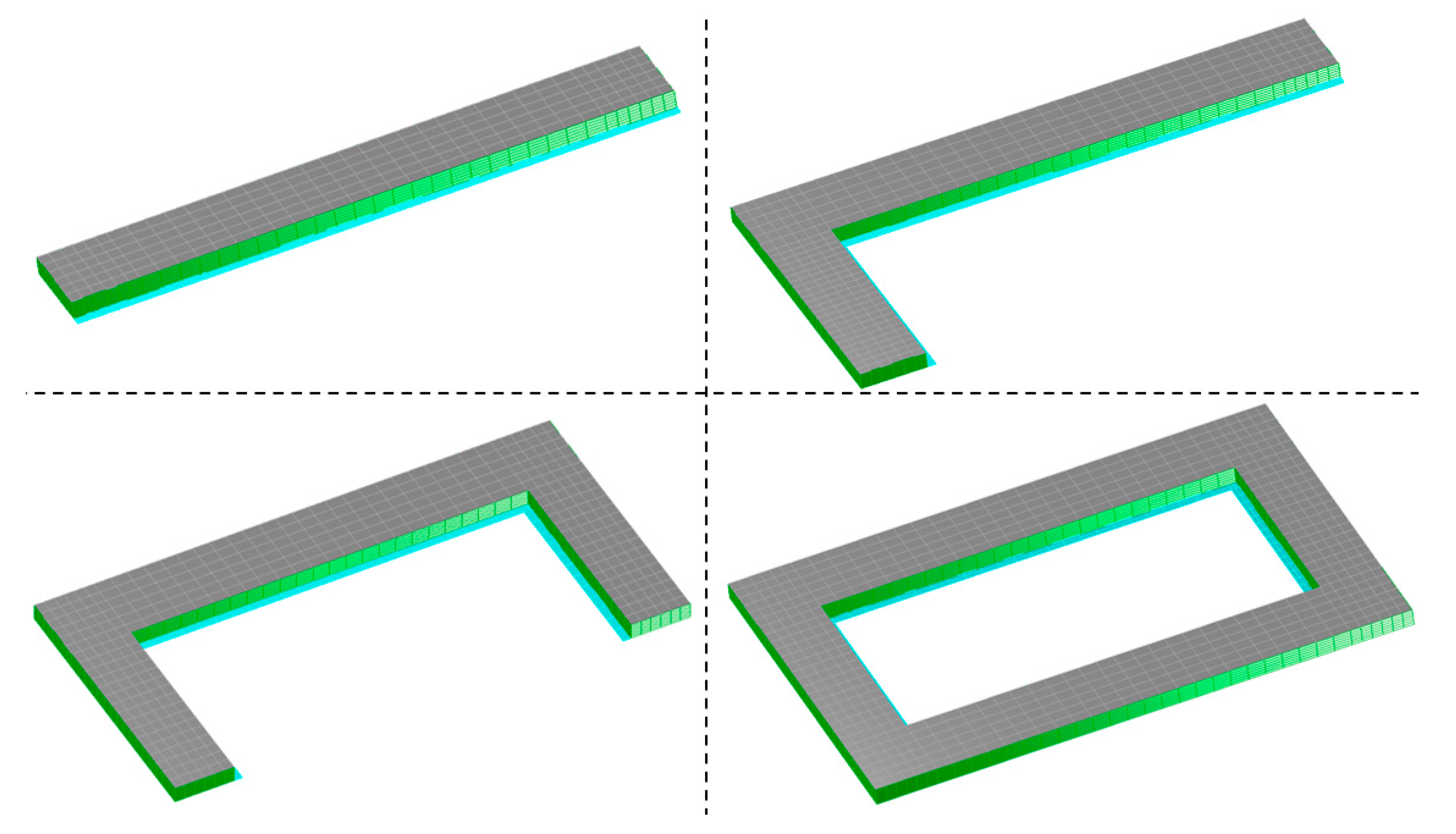
The patches of the floating breakwaters and the floating tanks for the numerical analysis are shown in Figure 3 and Figure 4. A thin layer of dipole damping plates (light blue) is placed at the inner sharp corner of the floating breakwaters, 4 m below the free surface. When there are floating tanks, the damping plates were also placed between the two tanks with the same damping coefficients adopted. The floating breakwaters can move in heave, roll, and pitch, while the floating tanks can move in six D.O.Fs with restraints from a special soft mooring system. The stiffness of the soft mooring system is represented by a linear restoring matrix in the numerical model. For more details of the numerical models of the floating tanks and the subsystem, refer to [22].
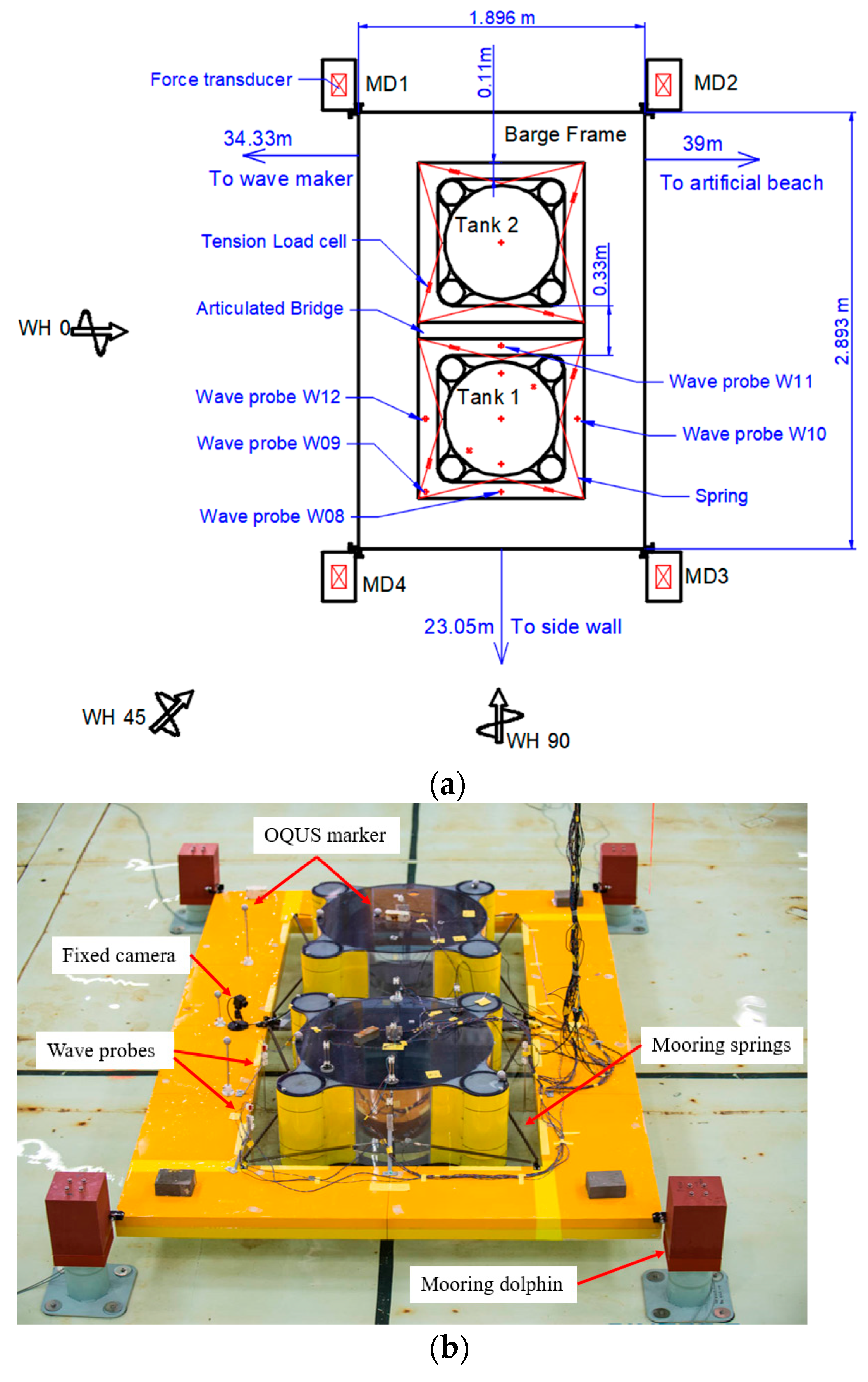
A series of model tests on the subsystem of floating hydrocarbon storage facility were completed in the Ocean Basin in SINTEF Ocean. The layout for the model tests and physical models of the subsystem are shown in Figure 5a,b, respectively. A Froude scaling factor of 1:45 was adopted for the model tests. Various loading conditions of the floating tanks and different environmental conditions in the coastal region of Singapore were tested. The 6 D.O.F motions of the floating barge frame and the floating tanks and free surface elevations in the narrow gaps were measured. Refer to [22,28] for more details on the model test setup.
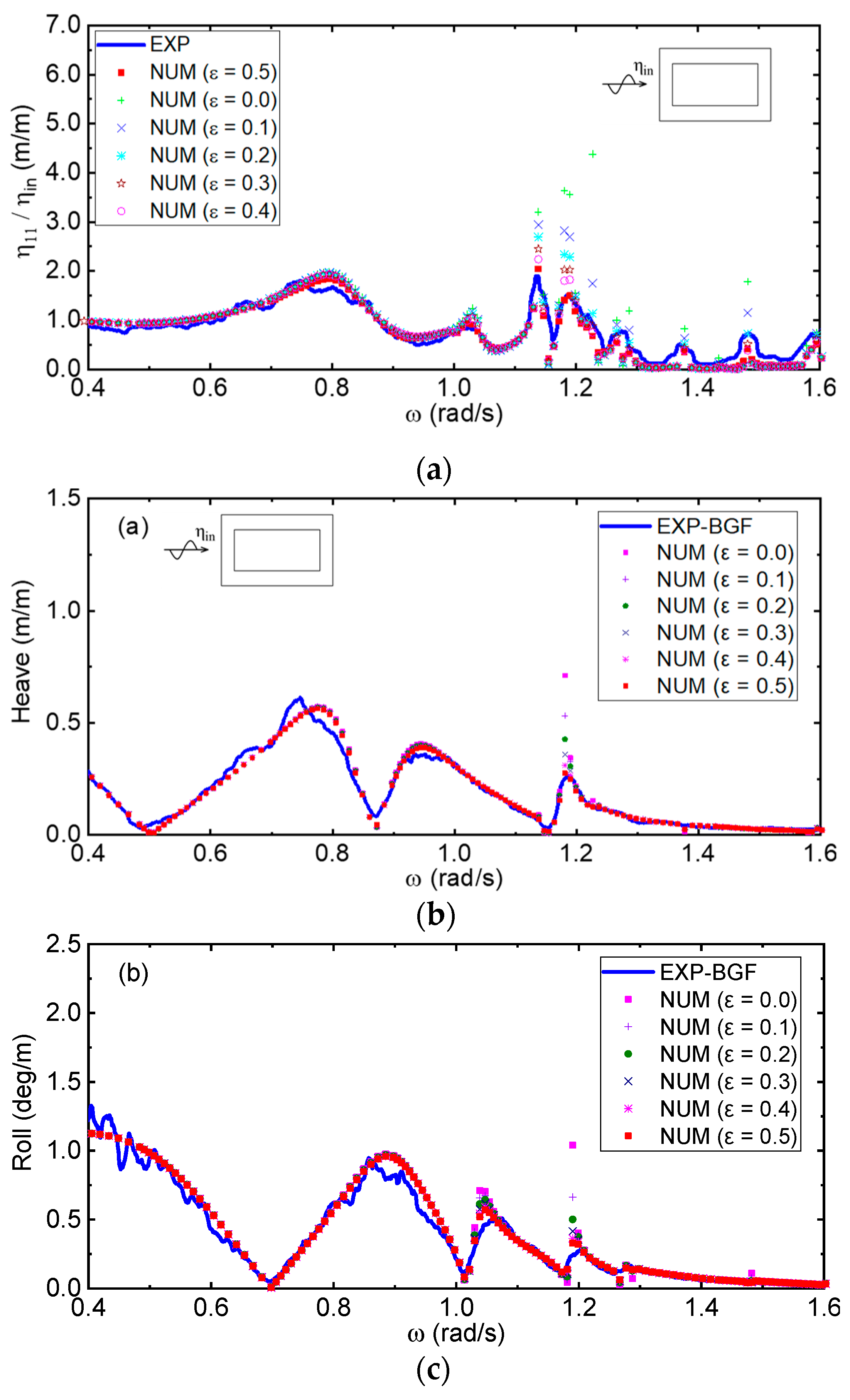
The model test results were used to validate the numerical models, and the validations were conducted for both the barge frame alone and the subsystem (barge frame and two floating tanks). The free surface elevations and the motions of the floating tanks and the barge frame were measured. Figure 6a–c show an example of the comparison between the numerical and experimental motion response amplitude operator (RAO) of the free surface and roll motion for the case of barge frame alone with different levels of dissipation factors. Note that the RAOs of free surface elevations are, in fact, the wave transmission factors for different wave frequencies, and a smaller RAO indicates a better performance of floating breakwater. The undamped numerical results overpredict the responses near the resonant frequencies, as expected. The numerical results using the dissipation factor ε = 0.5 show very good agreement with the experimental results for almost all the resonant modes. So, this value is adopted for further studies here.
4. Results and Discussion
4.1. Floating Breakwaters without the Presence of Floating Tanks
In this section, the motion responses of the floating breakwaters and their effectiveness in reducing wave transmission are investigated. The latter is evaluated for six locations in the sheltered water, as shown in Figure 2. Two incident wave directions (0 deg and 45 deg) are considered, which are typical in coastal waters.
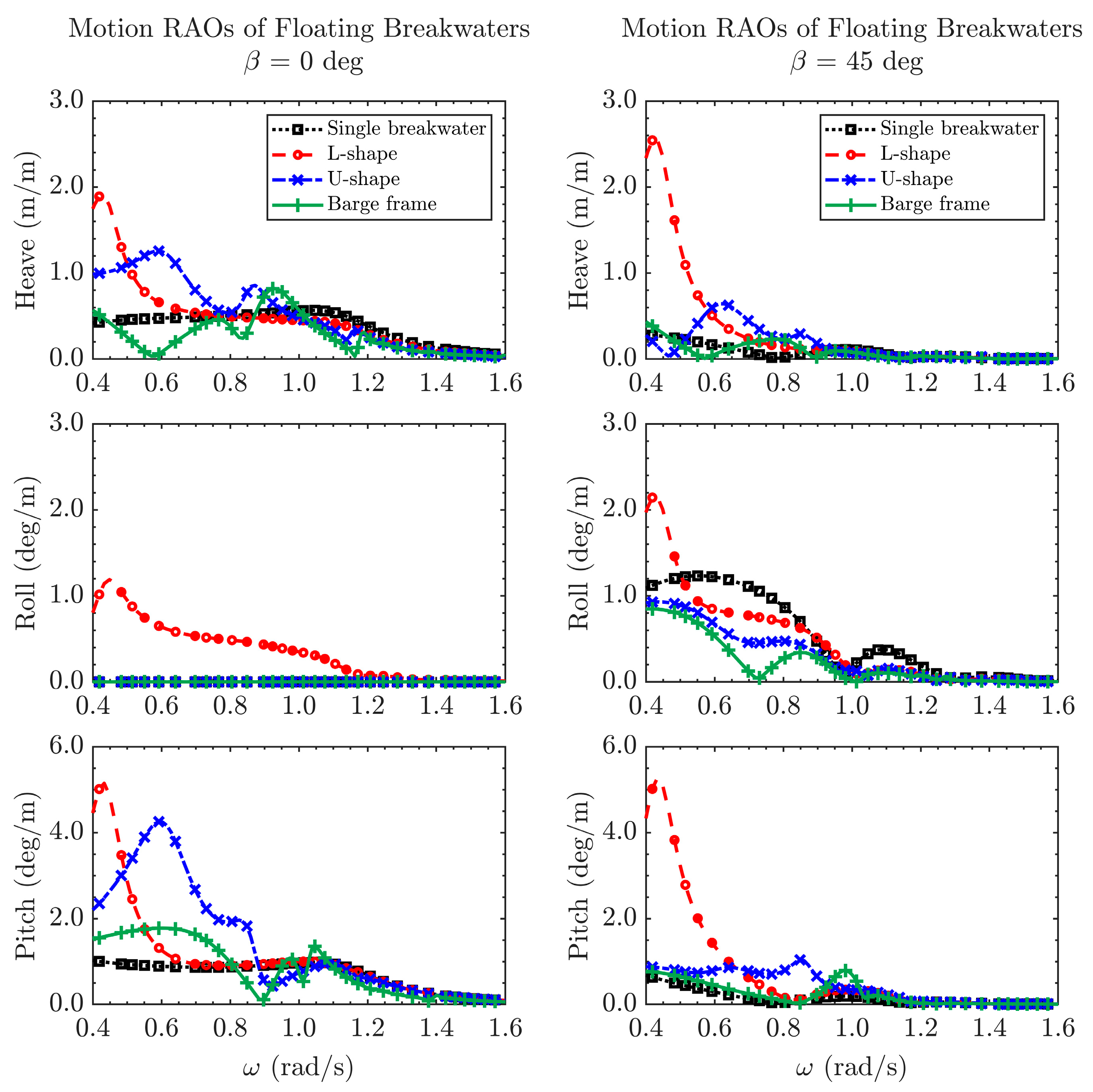
Figure 7 shows the motion RAOs of the floating breakwaters. When the incident waves are perpendicular to the floating breakwaters, all three configurations of floating breakwater have smaller motion than the conventional single-barge floating breakwater for wave frequencies higher than 1.0 rad/s. However, when rad/s, the L-shape and U-shape floating breakwater show much larger pitch motion, and roll motion are present for the L-shape floating breakwaters due to the unsymmetric shape. A similar trend can be found when the wave angle of incidence increases. Among these three configurations of the floating breakwaters, the barge frame has the best motion performance.
The good motion performance of the barge frame is associated with the several cancellation frequencies, which can be identified from both Figure 6b and Figure 7. The cancellation frequency is mainly due to the cancellation of excitation forces acting on the two parallel barges (perpendicular to the propagation direction of incident waves). It can be examined by checking L/λ, the ratio between the incident wavelength and the characteristic length L of the barge frame. L is the distance between the two transverse barges of the barge frame from center to center. An example is given for the barge frame in 0 deg waves. Table 3 lists the cancellation frequencies for both heave and pitch and the corresponding L/λ. It can be found that when L/λ is close to 0.5 (ω = 0.580 rad/s) and 1.5 (ω = 0.898 rad/s), the heave motion RAO is about zero; when L/λ is close to 1.0 (ω = 1.160 rad/s), the pitch motion RAO is about zero. A simple explanation may be provided for the cancellation phenomenon: when L/λ is close to 0.5, the wave excitation forces in the vertical direction on the two transverse barges are near out of phase, leading to small excitation in heave; when L/λ is close to 1.0, the wave excitation forces on the two transverse barges are near in phase, leading to small excitation force in pitch. This feature helps reduce the motions of the barge frame and is advantageous because the space on the breakwater can also be utilized.
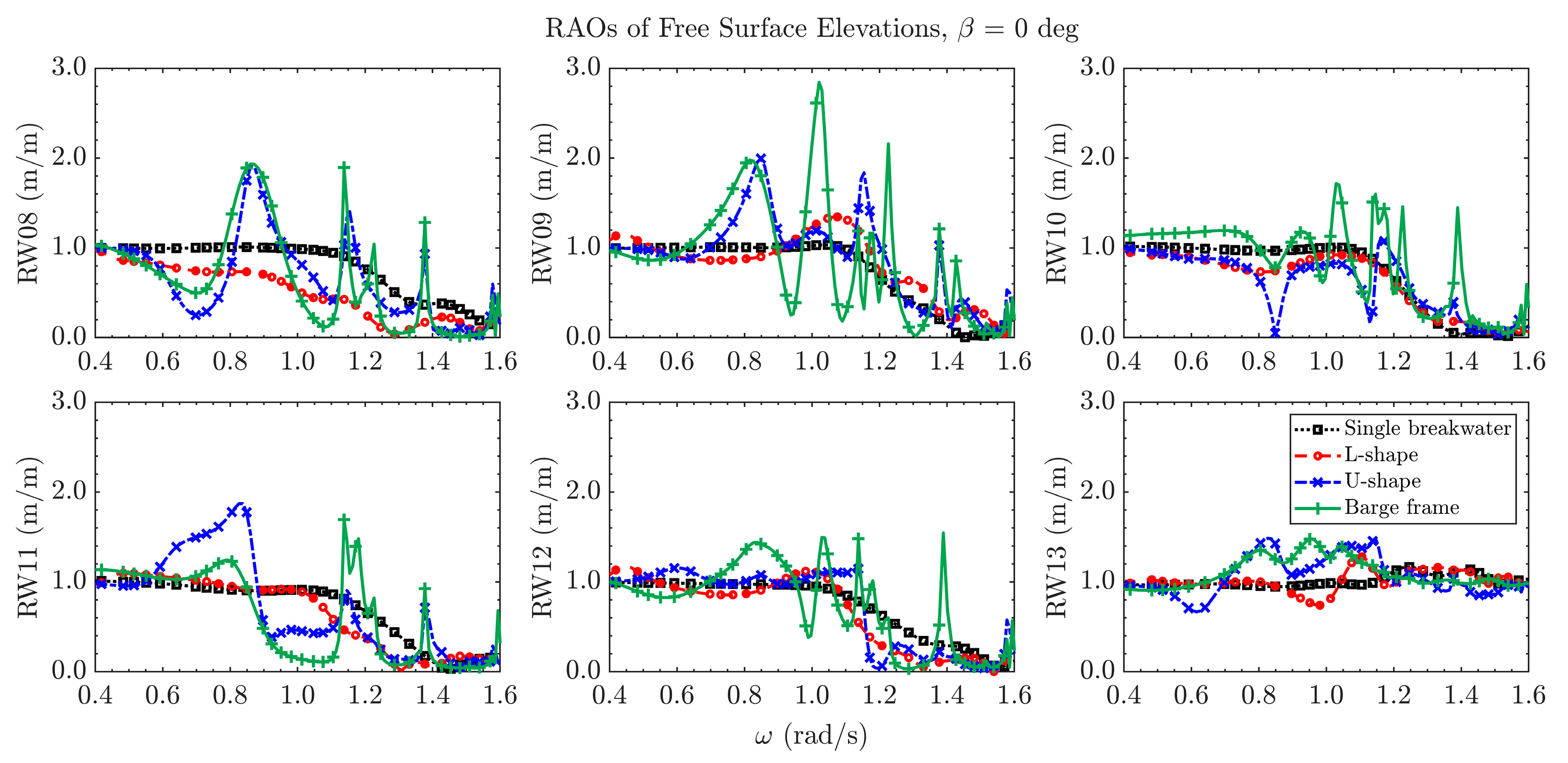
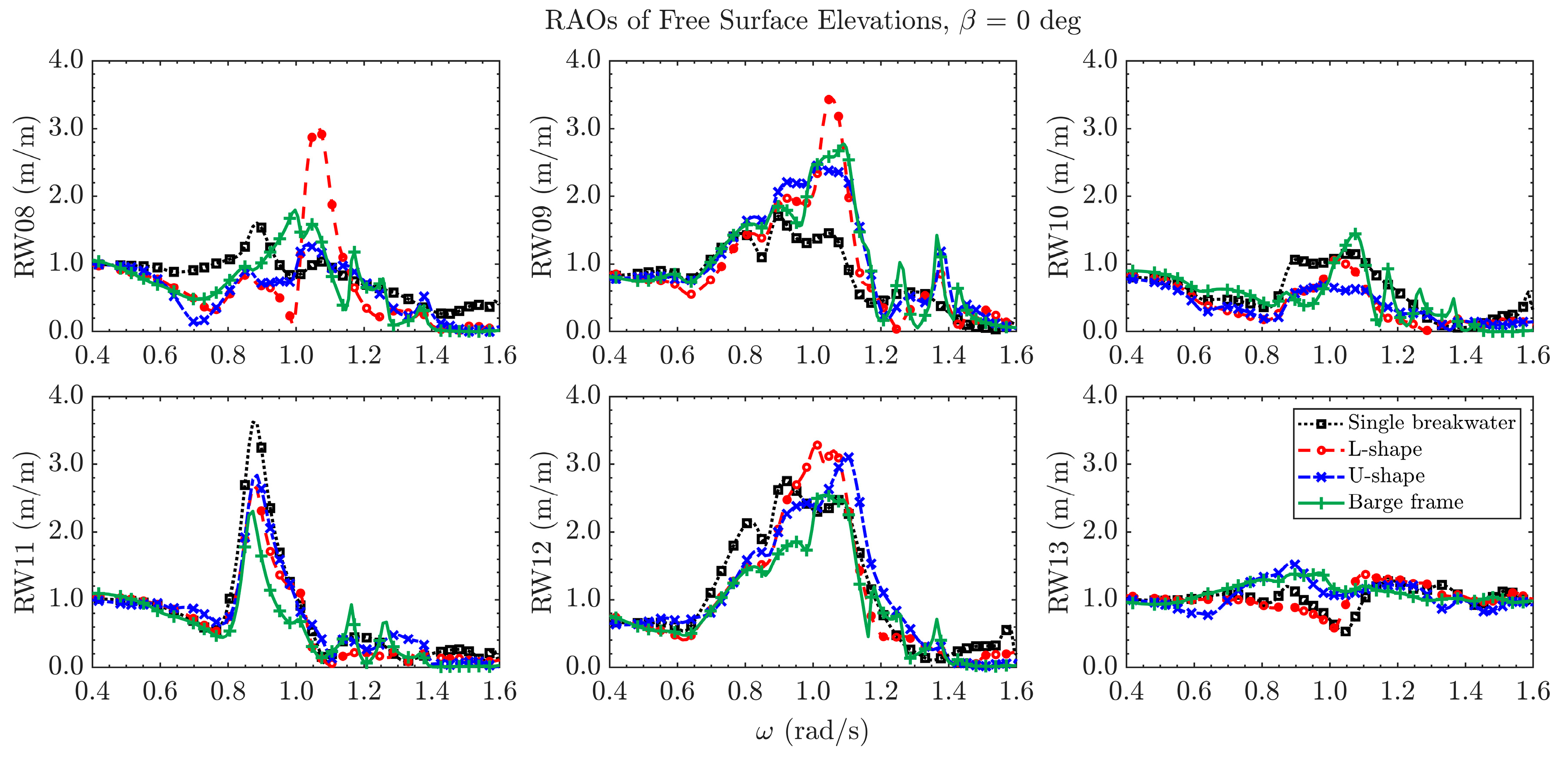
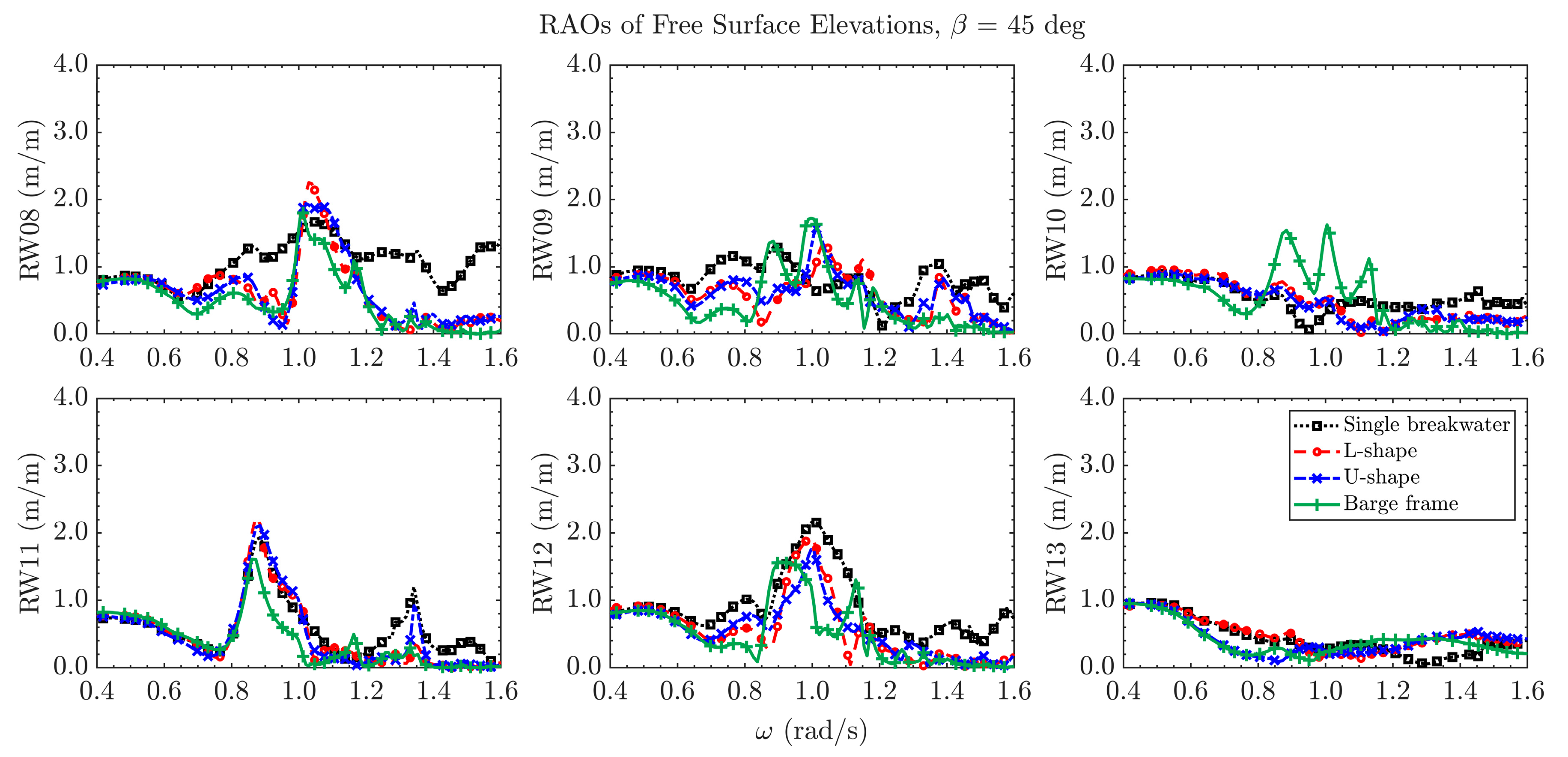
The RAOs of free surface elevations at the six locations in the free surface behind the sheltering barge are also reviewed, as shown in Figure 8 and Figure 9. It can be found that in the 0 deg incident wave direction, the single floating breakwater is effective when the wave frequency is higher than 1.1 rad/s. By changing the configuration to L-shape, the RAOs of free surface elevations reduce in a much broader wave frequency range than those of the conventional floating breakwater. Compared to the L-shape floating breakwater, the barge frame and U-shape floating breakwater tend to bring in a few resonant fluid motion modes, which lead to large RAOs of the free surface elevations at certain resonant frequencies. Apart from the resonant frequencies, the U-shape breakwater and the barge frame present better performance than the L-shape barges, especially in oblique seas where the resonant fluid motions significantly reduce. In general, the L-shape floating breakwater shows better performance than the conventional single-barge floating breakwater, while the performance of the other two configurations depends on the incident wave conditions. None of the configurations prove effective for wave frequencies ω < 0.4 rad/s (wave period T > 15.7 s), as the wavelengths are too long to be affected by the floating breakwater. Still, the limitation may not be too severe for relatively protected coastal waters where such long period swells may not be present with any significant amplitude. In deep water conditions where such waves may be more significant, additional measurements may be adopted to improve the performance of floating breakwaters, such as increasing the width of the floating breakwater. This is beyond the scope of the present study.
4.2. Floating Breakwaters with the Presence of Floating Tanks
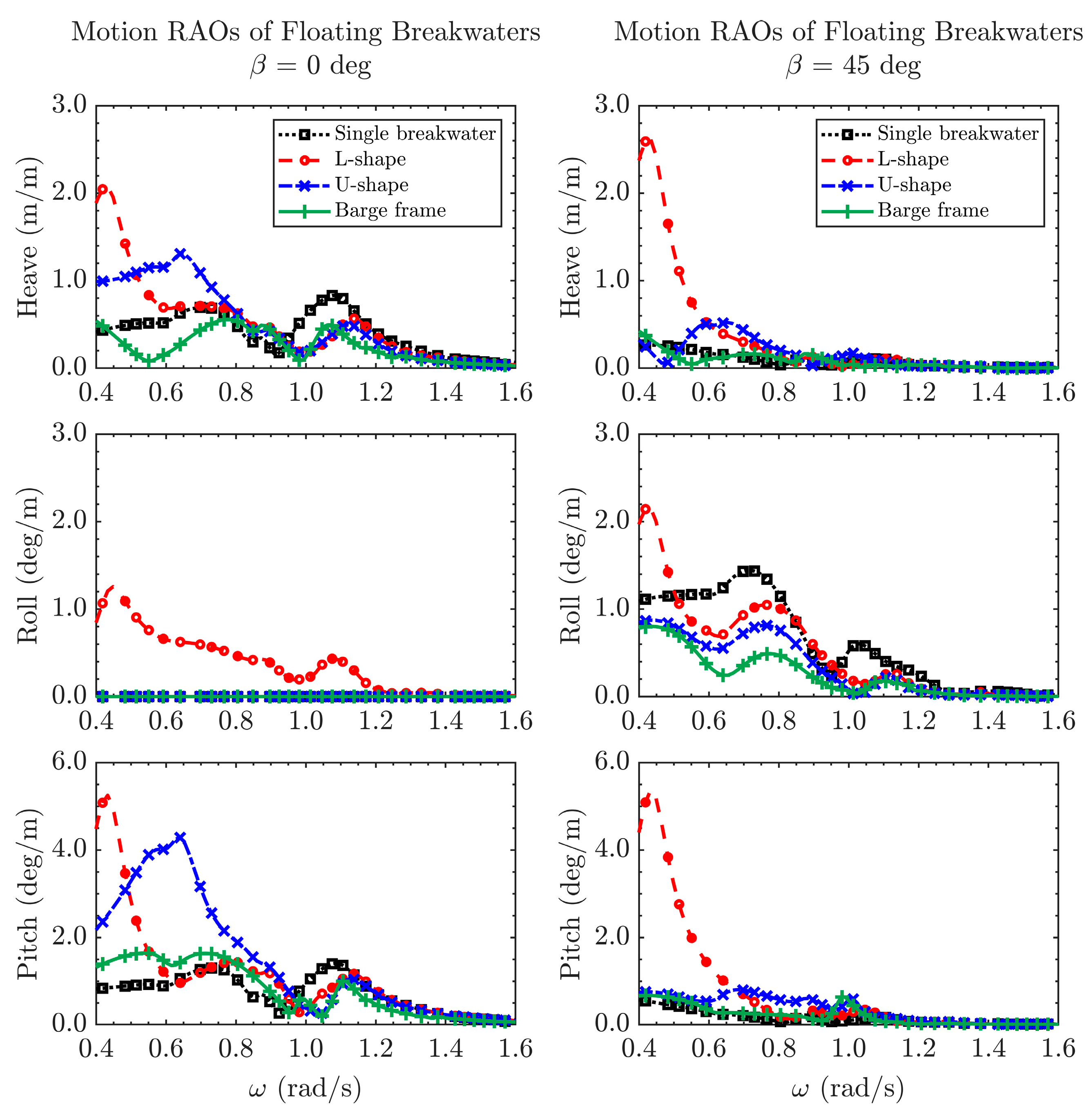
In this section, the performance of the floating breakwaters in different configurations is further investigated with the presence of the two floating tanks. Figure 10 shows the motion RAOs of the floating breakwaters. A further reduction of the motion RAOs can be found for both wave directions when there are no floating tanks. The motion performance of the barge frame is again the best among the four explored configurations.
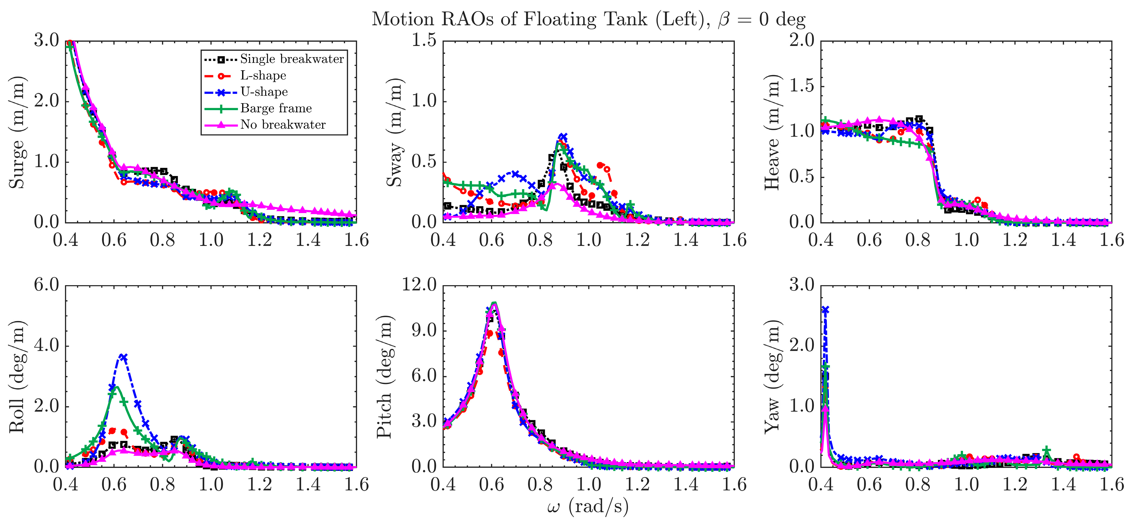
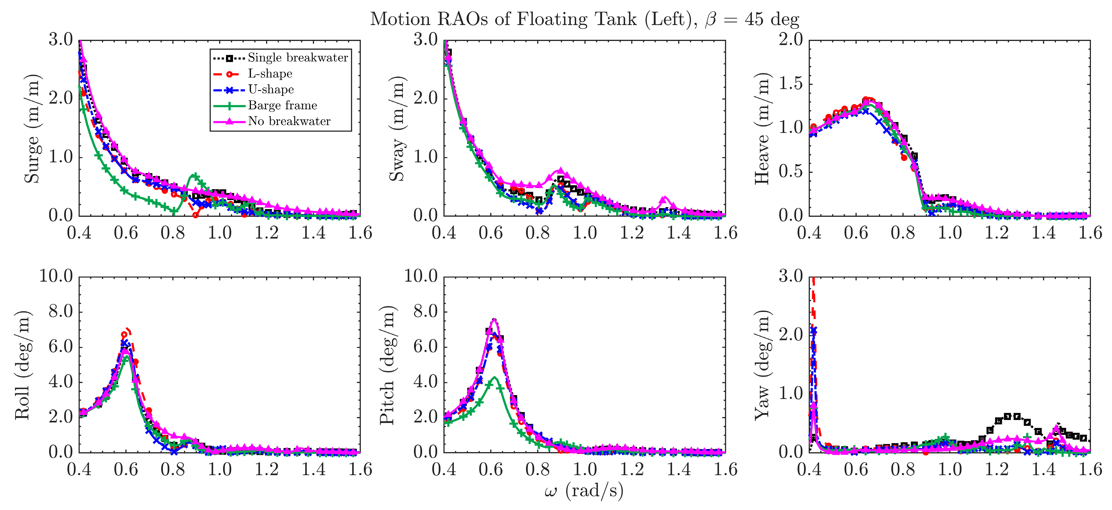
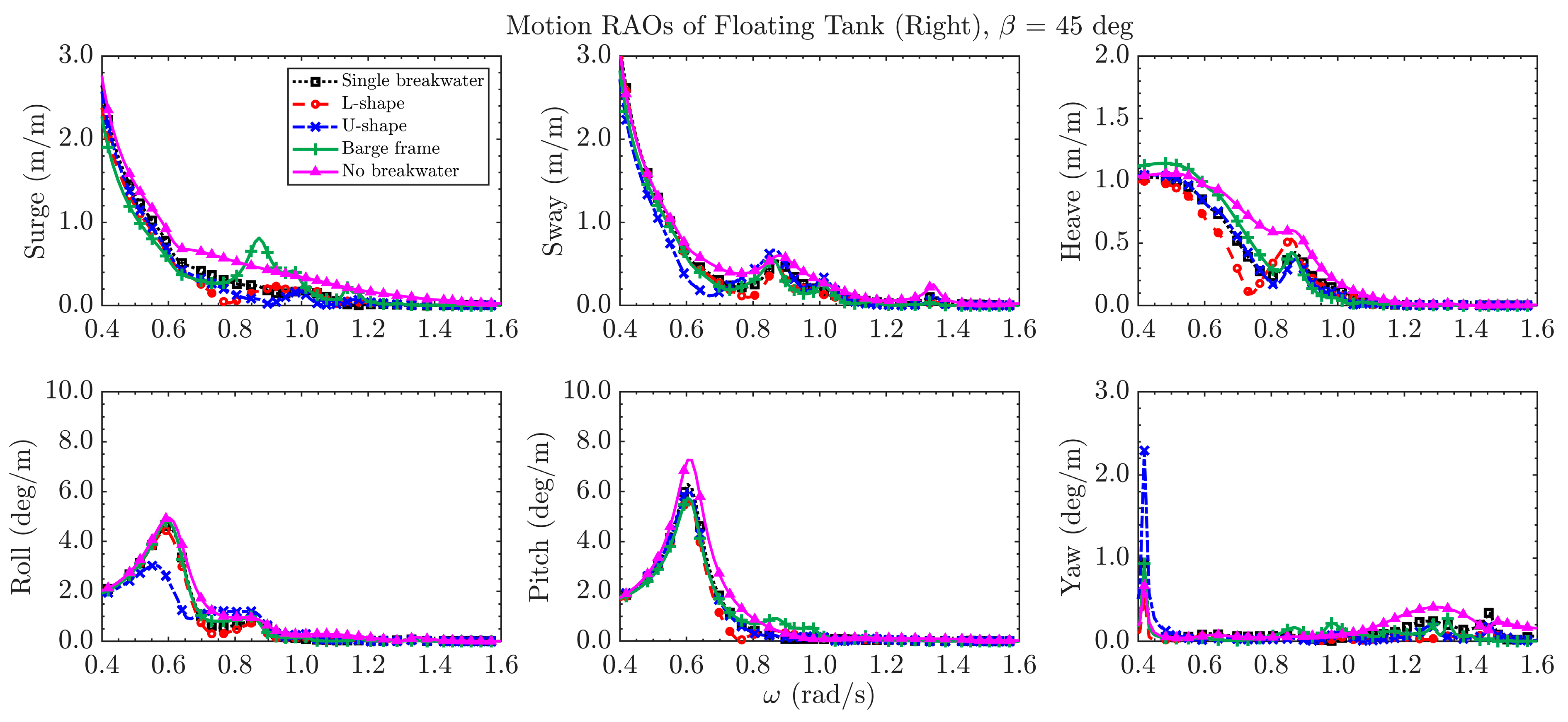
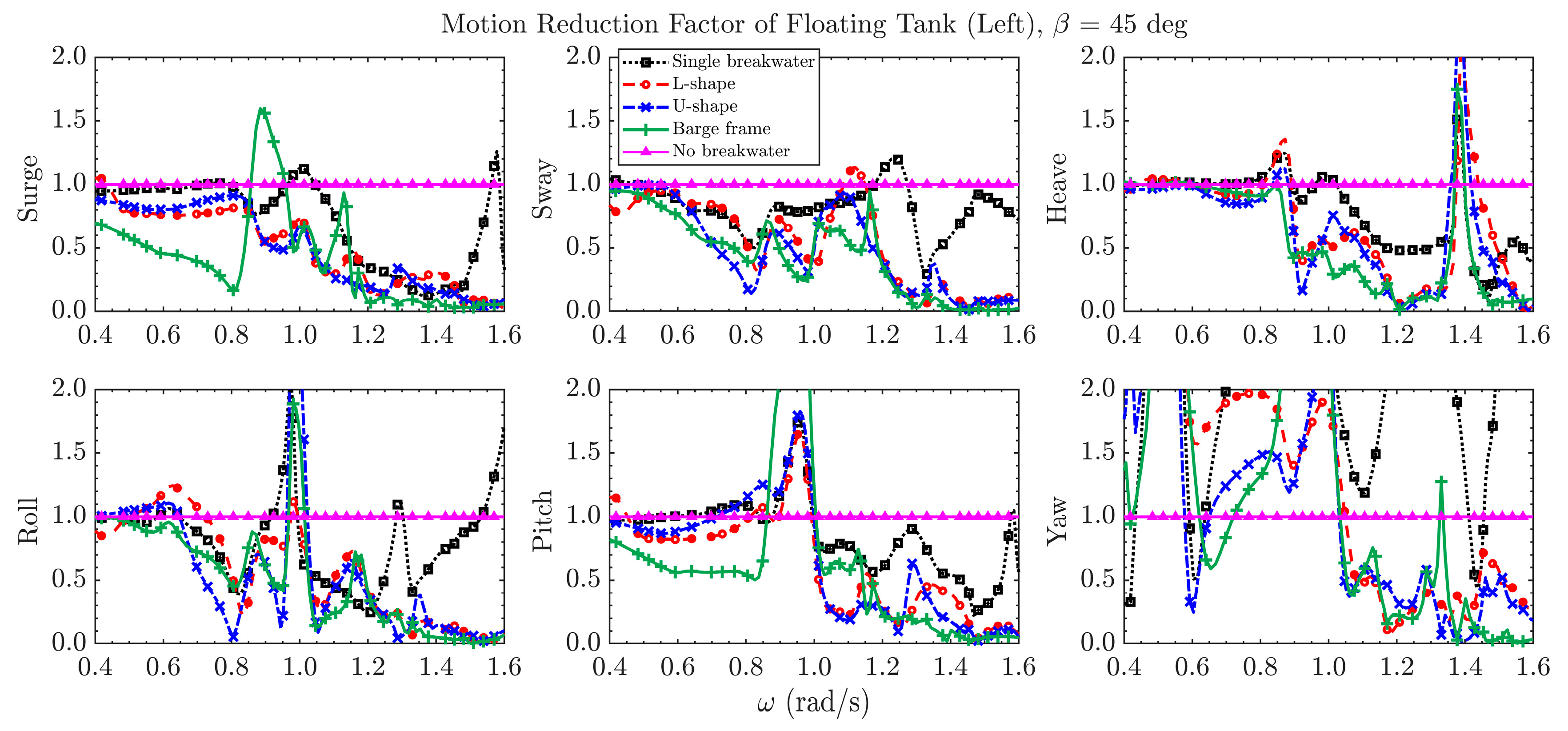
Figure 11 and Figure 12 show the motion RAOs of the left floating tank in 0 and 45 deg incident wave directions, and Figure 13 shows the motion RAOs of the right tank in 45 deg incident wave direction. The results of a case without the presence of any floating breakwaters are also presented for comparison. It can be found that the floating breakwater can effectively reduce the surge and heave RAOs of both floating tanks for both incident wave directions. The barge frame shows better effectiveness than the other configurations for rad/s, especially in 45 deg incident wave direction. However, it is noted that the floating tanks have larger motion RAOs in sway and roll in 0 deg incident wave direction with the existence of floating breakwaters. The sway RAOs can reach a similar level as those in the surge motion that is induced by incident waves.
The aforementioned phenomenon occurs even though a single floating breakwater is adopted. It indicates that additional motions (those out of the plane of the incident waves) might be excited, mainly due to the hydrodynamic interactions when a floating breakwater is placed close to the protected floating bodies. These cannot be identified from the analysis of floating breakwaters only. Therefore, a careful evaluation of the floating breakwater’s effectiveness should be conducted if it is adopted to protect floating bodies in its sheltered zone, and attention should be paid to if the influence of the additional out-of-plane motions matters for the design.
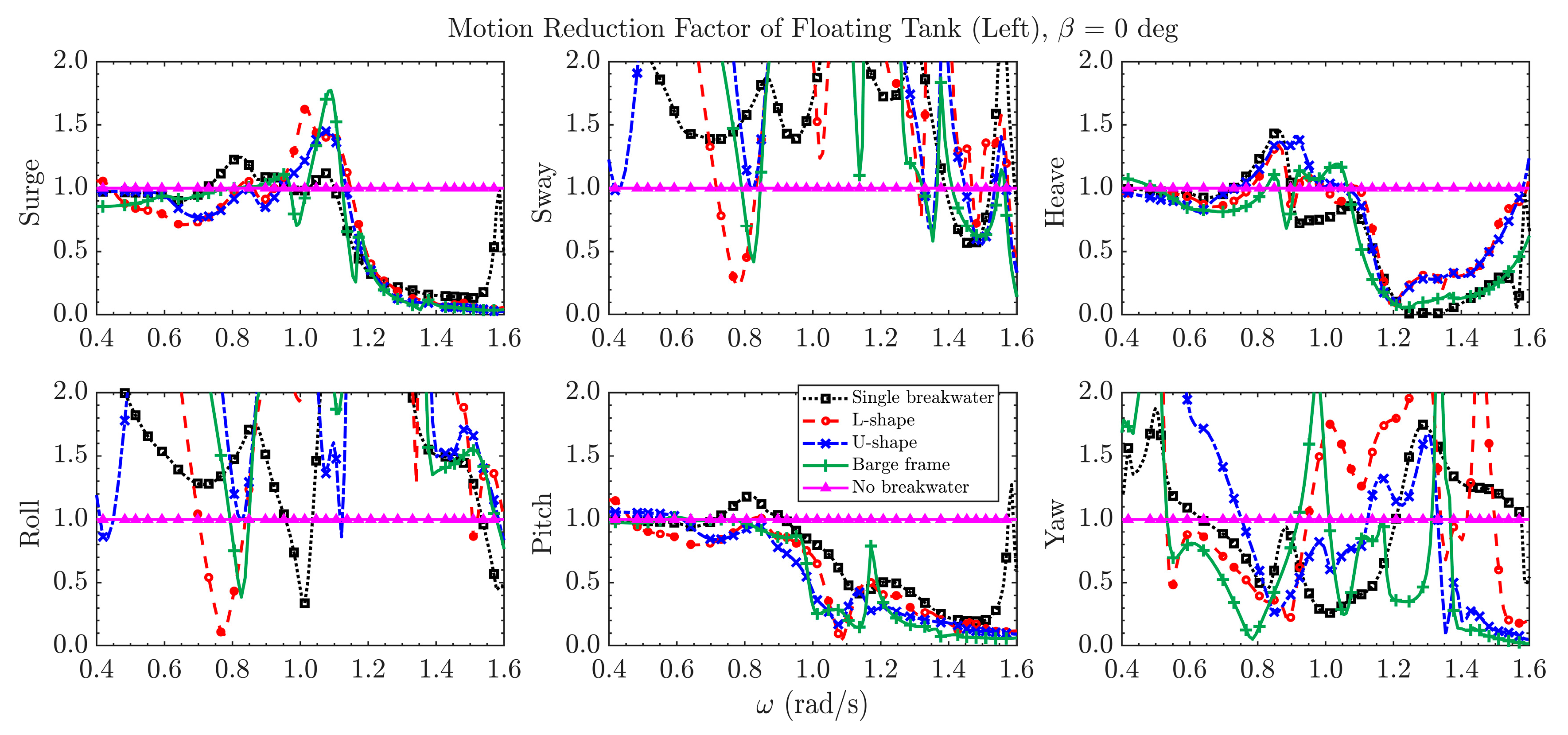
To further illustrate the effectiveness of the floating breakwaters on the motion reduction of the floating tanks, a reduction factor κ is introduced to quantify the effectiveness, and κ is defined as
where and are the modulus of the numerical RAOs of the floating tanks with and without floating breakwaters, respectively. Following this definition, means the floating breakwater can effectively reduce the motion RAOs of the floating tanks.
Figure 14 and Figure 15 show the effectiveness factor for the two floating tanks in the two incident wave directions. In the 0 deg wave direction, it can be found that the floating breakwaters can effectively reduce the surge and heave motion of the floating tanks, especially in the frequency range higher than 1.1 rad/s. The three special configurations of floating breakwater can effectively reduce pitch motion better than the conventional floating breakwater. In addition, the transverse motions (sway and roll) are strongly related to the existence of the floating breakwaters, which again indicates the importance of considering hydrodynamic interactions when evaluating the effectiveness of floating breakwaters. Note that the large in sway, roll, and yaw is mainly because of the very small RAOs when there is no breakwater. In the 45 deg wave direction, the barge frame shows better performance than the conventional floating breakwater and the other configurations, especially when rad/s.
In addition to the motion responses, the free surface elevations in the gaps may also influence the operability of the floating facilities and are, thus, evaluated herein. The RAOs of free surface elevations at the six selected locations for the two different incident wave directions are plotted in Figure 16 and Figure 17. It is found that resonant fluid motions between the floating tanks and the breakwater (RW09 and RW12) appear for both conventional single-barge floating breakwater and those of the three special configurations in the 0 deg wave direction. These are believed to be related to the increase of sway responses as shown in Figure 12 and Figure 13. It can also be found that the motion RAOs of the free surface elevations dramatically reduces with the increase of wave obliquity. Among these configurations, the barge frame leads to smaller free surface elevations, especially in 45 deg wave direction.
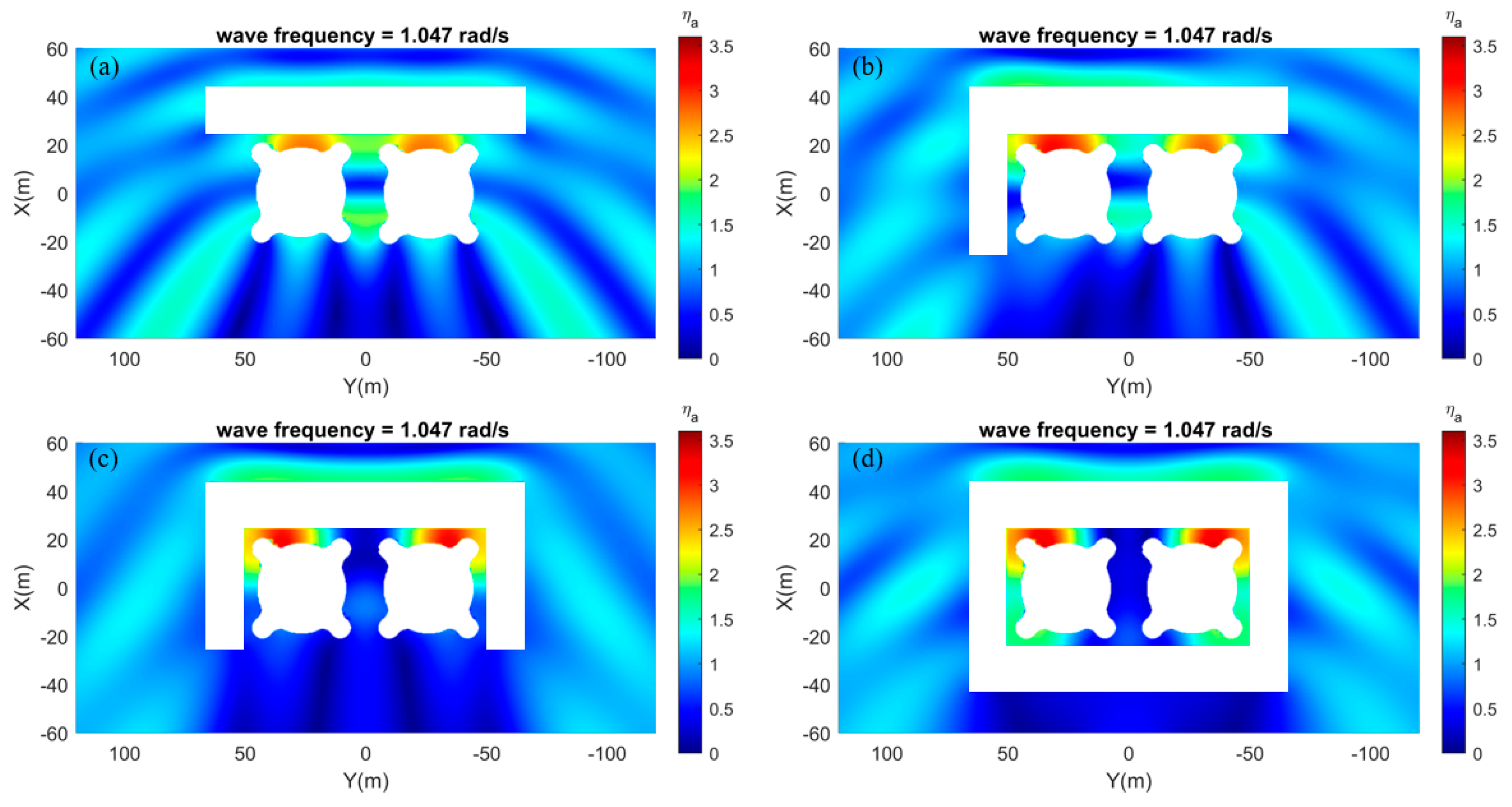
By investigating the free surface elevations over the entire free surface around the floating bodies, the resonant fluid motions in the narrow gaps can be clearly identified (see Figure 18 and Figure 19). At wave frequency 1.047 rad/s, the RAOs can reach up to 3.5 in the 0 deg wave direction. The resonant motions exist also for a single conventional floating breakwater. Noting that the wave period is around 6 s, which is commonly seen in coastal waters, significant influence on both the floating tanks and breakwaters is expected. Engineering approaches may be adopted to reduce the resonant fluid motions. Again, these results show it is important to evaluate the effectiveness of floating breakwaters together with the protected floating bodies.
5. Conclusions
In this paper, floating breakwaters of three special configurations, namely L-shape, U-shape, and barge frame are investigated and compared to their conventional counterparts through case studies on a subsystem of floating hydrocarbon storage facility. The effectiveness of the floating breakwaters is evaluated for the cases, with and without the existence of the protected floating tanks, through numerical analysis. The free surface elevations in the sheltered zone and the motion responses of the floating breakwaters and floating tanks are assessed. The major findings are summarized as follows:
When there is no protected floating body in the sheltered zone, the L-shape and U-shape floating breakwaters show larger motions in longer waves ( rad/s) than the barge frame and the single straight breakwater. The barge frame has lower responses due to the cancellation frequencies, which is related to the distance between the two parallel floating barges. Fluid resonant modes were identified in the moonpool of the barge frame, leading to significant increases of the free surface elevations which are amplified at the resonant frequencies. Apart from these frequencies, the free surface elevations are reduced to a low level, especially in the 45 degree wave direction. The actual performance of the barge frame will, therefore, depend on the characteristic parameters of the realistic sea states.
When the floating tanks are placed close to the breakwaters in the sheltered water, the motion RAOs of all the investigated breakwaters reduce. The effectiveness of the floating breakwaters on the motion reduction of the floating tanks varies, and the barge frame shows the best performance in shorter waves for both wave directions. Noticeable sway, roll, and yaw motions are excited due to the hydrodynamic interactions and fluid resonant motions for all floating breakwaters, including the conventional ones. The existence of fluid resonant motions may significantly influence the operability of the floating bodies in the sheltered water. Therefore, it is important to consider the interactions when evaluating the effectiveness of the floating breakwaters. Since the performance of the barge frame is the best in the oblique seas, it would be useful by adjusting the orientation of the barge frame according to the principal direction of the incident waves. It is especially feasible for coastal waters where a predominant direction occurs.
The present studies reveal the performance of floating breakwaters of different special configurations, especially when they are placed close to the protected floaters. The importance of considering hydrodynamic dynamic interactions and resonant fluid motions in the analysis of floating breakwaters is demonstrated. Although the results and findings are derived for a simplified configuration of the hydrocarbon storage facility, they may be a useful reference for the design of floating breakwaters for many types of marine floating structures in space-limited coastal water.
The recommended future works include further evaluating the effectiveness of the special configurations of floating breakwaters in irregular waves considering wave spreading and exploring engineering approaches to reduce the fluid resonant motions in the narrow gaps between the floating tanks and breakwaters.
Author Contributions
Conceptualization, A.R.M. and C.Z.; methodology, software, validation, C.Z.; writing—original draft preparation, C.Z.; writing—review and editing, A.R.M.; supervision, A.R.M. Both authors have read and agreed to the published version of the manuscript.
Funding
This research is funded by A*STAR under its RIE 2020 Industry Alignment Fund (Grant No: A19F1a0104).
Institutional Review Board Statement
Not applicable.
Informed Consent Statement
Not applicable.
Data Availability Statement
Not applicable.
Acknowledgments
The research work was partly completed during the first author’s Ph.D. study at the National University of Singapore, and the financial support from the university through the Research Scholarship is acknowledged. Also, this research is supported by A*STAR under its RIE 2020 Industry Alignment Fund (Grant No: A19F1a0104).
Conflicts of Interest
The authors declare no conflict of interest.
References
- Dai, J.; Zhang, C.; Lim, H.V.; Ang, K.K.; Qian, X.; Wong, J.L.H.; Tan, S.T.; Wang, C.L. Design and construction of floating modular photovoltaic system for water reservoirs. Energy 2020, 191, 116549. [Google Scholar] [CrossRef]
- Otto, W.J.; Waals, O.J.; Bunnik, T.H.J.; Cresp, J. Optimization of Wave Induced Motions and Forces on a Floating Island. In Proceedings of the 29th International Ocean and Polar Engineering Conference, Honolulu, HI, USA, 16–21 June 2019; pp. 3120–3126. [Google Scholar]
- Ren, N.; Zhang, C.; Magee, A.R.; Hellan, Ø.; Dai, J.; Ang, K.K. Hydrodynamic analysis of a modular multi-purpose floating structure system with different outermost connector types. Ocean Eng. 2019, 176, 158–168. [Google Scholar] [CrossRef]
- Nguyen, H.; Park, J.; Han, M.; Wang, C.; Abdussamie, N.; Penesis, I.; Howe, D. Representative Transmission Coefficient for Evaluating the Wave Attenuation Performance of 3D Floating Breakwaters in Regular and Irregular Waves. J. Mar. Sci. Eng. 2021, 9, 388. [Google Scholar] [CrossRef]
- McCartney, B.L. Floating Breakwater Design. J. Waterw. Port Coastal Ocean Eng. 1985, 111, 304–318. [Google Scholar] [CrossRef]
- Dai, J.; Wang, C.M.; Utsunomiya, T.; Duan, W.H. Review of recent research and developments on floating breakwaters. Ocean Eng. 2018, 158, 132–151. [Google Scholar] [CrossRef]
- Deng, Z.; Wang, L.; Zhao, X.; Huang, Z. Hydrodynamic performance of a T-shaped floating breakwater. Appl. Ocean Res. 2019, 82, 325–336. [Google Scholar] [CrossRef]
- Ruol, P.; Martinelli, L.; Pezzutto, P. Formula to Predict Transmission for π-Type Floating Breakwaters. J. Waterw. Port Coastal Ocean Eng. 2013, 139, 1–8. [Google Scholar] [CrossRef] [Green Version]
- Ji, C.; Deng, X.; Cheng, Y. An experimental study of double-row floating breakwaters. J. Mar. Sci. Technol. 2018, 24, 359–371. [Google Scholar] [CrossRef]
- Diamantoulaki, I.; Angelides, D.C. Analysis of performance of hinged floating breakwaters. Eng. Struct. 2010, 32, 2407–2423. [Google Scholar] [CrossRef]
- Loukogeorgaki, E.; Michailides, C.; Angelides, D.C. Hydroelastic analysis of a flexible mat-shaped floating breakwater under oblique wave action. J. Fluids Struct. 2012, 31, 103–124. [Google Scholar] [CrossRef]
- Loukogeorgaki, E.; Yagci, O.; Kabdasli, M.S. 3D Experimental investigation of the structural response and the effectiveness of a moored floating breakwater with flexibly connected modules. Coast. Eng. 2014, 91, 164–180. [Google Scholar] [CrossRef]
- Zhao, X.L.; Ning, D.Z.; Zou, Q.P.; Qiao, D.S.; Cai, S.Q. Hybrid floating breakwater-WEC system: A review. Ocean Eng. 2019, 186, 106126. [Google Scholar] [CrossRef]
- Han, M.; Wang, C. Modelling wide perforated breakwater with horizontal slits using Hybrid-BEM method. Ocean Eng. 2021, 222, 108630. [Google Scholar] [CrossRef]
- Martinelli, L.; Ruol, P.; Zanuttigh, B. Wave basin experiments on floating breakwaters with different layouts. Appl. Ocean Res. 2008, 30, 199–207. [Google Scholar] [CrossRef]
- Tay, Z.Y. Performance and wave impact of an integrated multi-raft wave energy converter with floating breakwater for tropical climate. Ocean Eng. 2020, 218, 108136. [Google Scholar] [CrossRef]
- Syed, S.A.; Mani, J.S. Performance of multiple pontoons floating breakwater—A numerical approach. In Proceedings of the Sixth International Conference on Civil Engineering in the Oceans, Baltimore, MD, USA, 20–22 October 2004. [Google Scholar] [CrossRef]
- Williams, A.; Lee, H.; Huang, Z. Floating pontoon breakwaters. Ocean Eng. 2000, 27, 221–240. [Google Scholar] [CrossRef]
- Teng, B.; Ning, D.-Z.; Goda, Y.; Kioka, W.; Nadaoka, K. Wave diffraction from a uniform cylinder in front of vertical walls. In Proceedings of the 2nd International Conference, Asian and Pacific Coasts, Makuhari, Japan, 29 February–4 March 2004. [Google Scholar] [CrossRef]
- Zheng, S.; Zhang, Y. Wave diffraction from a truncated cylinder in front of a vertical wall. Ocean Eng. 2015, 104, 329–343. [Google Scholar] [CrossRef]
- Konispoliatis, D.N.; Mavrakos, S.A. Theoretical analysis of a vertical cylindrical floater in front of an orthogonal breakwater. Fluids 2020, 5, 135. [Google Scholar] [CrossRef]
- Zhang, C.; Fonseca, N.; Ren, N.; Magee, A.R.; Ang, K.K. Experimental and numerical investigation of wave-induced hydrodynamic interactions of a sub-floating hydrocarbon storage tank system in shallow waters. Ocean Eng. 2020, 216, 108104. [Google Scholar] [CrossRef]
- Dai, J.; Ang, K.K.; Jin, J.; Wang, C.M.; Hellan, Ø.; Watn, A. Large floating structure with free-floating, self-stabilizing tanks for hydrocarbon storage. Energies 2019, 12, 3487. [Google Scholar] [CrossRef] [Green Version]
- Wan, L.; Han, M.; Jin, J.; Zhang, C.; Magee, A.R.; Hellan, Ø.; Wang, C. Global dynamic response analysis of oil storage tank in finite water depth: Focusing on fender mooring system parameter design. Ocean Eng. 2018, 148, 247–262. [Google Scholar] [CrossRef]
- Zhang, C.; Wan, L.; Magee, A.R.; Han, M.; Jin, J.; Ang, K.K.; Hellan, Ø. Experimental and numerical study on the hydrodynamic loads on a single floating hydrocarbon storage tank and its dynamic responses. Ocean Eng. 2019, 183, 437–452. [Google Scholar] [CrossRef]
- Lee, C.H.; Newman, J.N. Wamit—User Manual Version 7.0; WAMIT Inc: Chestnut Hill, Ma, USA, 2013. [Google Scholar]
- Lee, C.H.; Zhu, X. Application of hyper-singular integral equations for a simplified model of viscous dissipation. In Proceedings of the 28th International Offshore and Polar Engineering Conference, Sapporo, Japan, 10–15 June 2018. [Google Scholar]
- Fonseca, N.; Chi, Z.; Rodrigues, J.M.; Ren, N.; Hellan, Ø.; Magee, A.R. Hydrodynamic model tests with a large floating hydrocarbon storage facility. In Proceedings of the International Conference on Offshore Mechanics and Arctic Engineering—OMAE, St. Julian’s, Malta, 3–6 November 2019; Volume 6, pp. 1–8. [Google Scholar]
Figure 1.
Configurations of floating breakwaters investigated in this paper.

Figure 2.
Definition of the global coordinate system and free surface point of interest: (a) cross-section, (b) plan view, (c) location of the monitored free surface point.
Figure 2.
Definition of the global coordinate system and free surface point of interest: (a) cross-section, (b) plan view, (c) location of the monitored free surface point.

Figure 3.
Patches for the numerical models of floating breakwaters of different configurations: single, L-shape, U shape, and barge frame. The light blue patches are the damping dipole plates.
Figure 3.
Patches for the numerical models of floating breakwaters of different configurations: single, L-shape, U shape, and barge frame. The light blue patches are the damping dipole plates.

Figure 4.
Patches for the numerical models of floating tanks. Note the light blue patches are the damping plates to model bottom skirts.
Figure 4.
Patches for the numerical models of floating tanks. Note the light blue patches are the damping plates to model bottom skirts.

Figure 5.
(a) Layout of model tests on the subsystem of floating hydrocarbon storage facility; (b) setup of physical models in the basin [22].
Figure 5.
(a) Layout of model tests on the subsystem of floating hydrocarbon storage facility; (b) setup of physical models in the basin [22].

Figure 6.
(a) RAOs of free surface elevations at the center of the sheltered water (RW11); (b) heave RAOs of the floating barge frame; and (c) roll RAOs of the floating barge frame in 90 deg incident wave direction [22].
Figure 6.
(a) RAOs of free surface elevations at the center of the sheltered water (RW11); (b) heave RAOs of the floating barge frame; and (c) roll RAOs of the floating barge frame in 90 deg incident wave direction [22].

Figure 7.
Motion RAOs of the floating breakwaters of different configurations in heave, roll, and pitch in 0 and 45 deg incident wave directions.
Figure 7.
Motion RAOs of the floating breakwaters of different configurations in heave, roll, and pitch in 0 and 45 deg incident wave directions.

Figure 8.
RAOs of free surface elevations at selected locations in the sheltered zone in 0 deg incident wave direction.
Figure 8.
RAOs of free surface elevations at selected locations in the sheltered zone in 0 deg incident wave direction.

Figure 9.
RAOs of free surface elevations at selected locations in the sheltered zone in 45 deg incident wave direction.
Figure 9.
RAOs of free surface elevations at selected locations in the sheltered zone in 45 deg incident wave direction.

Figure 10.
Motion RAOs of the floating breakwaters of different configurations in heave, roll, and pitch with the presence of two floating tanks in 0 and 45 deg incident wave directions.
Figure 10.
Motion RAOs of the floating breakwaters of different configurations in heave, roll, and pitch with the presence of two floating tanks in 0 and 45 deg incident wave directions.

Figure 11.
Motion RAOs of the left-hand-side floating tank with the different configurations of floating breakwaters in 0 deg incident wave direction.
Figure 11.
Motion RAOs of the left-hand-side floating tank with the different configurations of floating breakwaters in 0 deg incident wave direction.

Figure 12.
Motion RAOs of the left-hand-side floating tank with the different configurations of floating breakwaters in 45 deg incident wave direction.
Figure 12.
Motion RAOs of the left-hand-side floating tank with the different configurations of floating breakwaters in 45 deg incident wave direction.

Figure 13.
Motion RAOs of the right-hand-side floating tank with the different configurations of floating breakwaters in 45 deg incident wave direction.
Figure 13.
Motion RAOs of the right-hand-side floating tank with the different configurations of floating breakwaters in 45 deg incident wave direction.

Figure 14.
Effectiveness of the floating breakwater in motion reduction of the floating tanks in 0 deg incident wave direction.
Figure 14.
Effectiveness of the floating breakwater in motion reduction of the floating tanks in 0 deg incident wave direction.

Figure 15.
Effectiveness of the floating breakwater in motion reduction of the floating tanks in 45 deg incident wave direction.
Figure 15.
Effectiveness of the floating breakwater in motion reduction of the floating tanks in 45 deg incident wave direction.

Figure 16.
Motion RAOs of free surface elevations around the floating tanks with the different configurations of floating breakwaters in 0 deg wave direction.
Figure 16.
Motion RAOs of free surface elevations around the floating tanks with the different configurations of floating breakwaters in 0 deg wave direction.

Figure 17.
Motion RAOs of free surface elevations around the floating tanks with the different configurations of floating breakwaters in 45 deg wave direction.
Figure 17.
Motion RAOs of free surface elevations around the floating tanks with the different configurations of floating breakwaters in 45 deg wave direction.

Figure 18.
Amplitude of free surface elevations around the floating tanks and the breakwaters in 0 deg wave direction, with wave frequency of 1.047 rad/s for (a) conventional single floating breakwater, (b) L-shape, (c) U shape, and (d) barge frame.
Figure 18.
Amplitude of free surface elevations around the floating tanks and the breakwaters in 0 deg wave direction, with wave frequency of 1.047 rad/s for (a) conventional single floating breakwater, (b) L-shape, (c) U shape, and (d) barge frame.

Figure 19.
Amplitude of free surface elevations around the floating tanks and the breakwaters in 45 deg wave direction, with wave frequency of 1.047 rad/s for (a) conventional single floating breakwater, (b) L-shape, (c) U shape, and (d) barge frame.
Figure 19.
Amplitude of free surface elevations around the floating tanks and the breakwaters in 45 deg wave direction, with wave frequency of 1.047 rad/s for (a) conventional single floating breakwater, (b) L-shape, (c) U shape, and (d) barge frame.


Table 1.
Main particulars of the barge components and floating tanks.
| Barge Type | Main Particulars | Values (m) |
|---|---|---|
| Longer barge | Length | 130.2 |
| Beam | 18.0 | |
| Draft | 4.0 | |
| Shorter barge | Length | 49.3 |
| Beam | 15.0 | |
| Draft | 4.0 | |
| Floating tanks (empty) | Length and width | 37.63 |
| Draft | 6.22 | |
| Inner diameter | 33.00 |
Table 2.
Mass properties of the floating breakwaters and storage tanks.
| Parameters | Single | L-Shape | U-Shape | Barge Frame | Floating Tanks |
|---|---|---|---|---|---|
| Mass (kg) | 9,476,228 | 12,467,113 | 15,497,997 | 24,938,634 | 7,494,737 |
| COG-X (m) | 33.66 | 25.58 | 20.63 | 0.00 | 0.00 |
| COG-Y (m) | 0.00 | 13.82 | 0.00 | 0.00 | 0.00 |
| COG-Z (m) | −0.58 | −0.58 | −0.58 | −0.58 | 1.95 |
| Rxx (m) | 37.10 | 43.33 | 46.47 | 44.35 | 15.06 |
| Ryy (m) | 34.00 | 30.50 | 28.20 | 30.85 | 15.06 |
| Rzz (m) | 38.90 | 45.33 | 48.33 | 42.47 | 16.33 |
Table 3.
Cancellation frequencies identified from the motion RAOs of the barge frame in 0 deg incident wave direction.
Table 3.
Cancellation frequencies identified from the motion RAOs of the barge frame in 0 deg incident wave direction.
| Cancellation Frequency (rad/s) | Wavenumber k | λ (m) | L/λ | D.O.F |
|---|---|---|---|---|
| 0.580 | 0.049 | 128.2 | 0.52 | heave |
| 1.160 | 0.139 | 45.2 | 1.49 | heave |
| 0.898 | 0.089 | 70.6 | 0.95 | pitch |
Publisher’s Note: MDPI stays neutral with regard to jurisdictional claims in published maps and institutional affiliations. |
© 2021 by the authors. Licensee MDPI, Basel, Switzerland. This article is an open access article distributed under the terms and conditions of the Creative Commons Attribution (CC BY) license (https://creativecommons.org/licenses/by/4.0/).
Share and Cite
MDPI and ACS Style
Zhang, C.; Magee, A.R. Effectiveness of Floating Breakwater in Special Configurations for Protecting Nearshore Infrastructures. J. Mar. Sci. Eng. 2021, 9, 785. https://0-doi-org.brum.beds.ac.uk/10.3390/jmse9070785
AMA Style
Zhang C, Magee AR. Effectiveness of Floating Breakwater in Special Configurations for Protecting Nearshore Infrastructures. Journal of Marine Science and Engineering. 2021; 9(7):785. https://0-doi-org.brum.beds.ac.uk/10.3390/jmse9070785
Chicago/Turabian StyleZhang, Chi, and Allan R. Magee. 2021. "Effectiveness of Floating Breakwater in Special Configurations for Protecting Nearshore Infrastructures" Journal of Marine Science and Engineering 9, no. 7: 785. https://0-doi-org.brum.beds.ac.uk/10.3390/jmse9070785
Note that from the first issue of 2016, this journal uses article numbers instead of page numbers. See further details here.