Article

COLREGs Compliant Fuzzy-Based Collision Avoidance System for Multiple Ship Encounters

by
Yaseen Adnan Ahmed
1,
Mohammed Abdul Hannan
2,*,
Mahmoud Yasser Oraby
1 and
Adi Maimun
1
1
The Faculty of Mechanical Engineering, Universiti Teknologi Malaysia, Skudai 81310, Malaysia
2
Singapore Campus, The Faculty of Science, Agriculture & Engineering, Newcastle University, Newcastle upon Tyne NE1 7RU, UK
*
Author to whom correspondence should be addressed.
J. Mar. Sci. Eng. 2021, 9(8), 790; https://0-doi-org.brum.beds.ac.uk/10.3390/jmse9080790
Submission received: 17 June 2021 / Revised: 14 July 2021 / Accepted: 16 July 2021 / Published: 22 July 2021
(This article belongs to the Section Ocean Engineering)

Abstract

:
As the number of ships for marine transportation increases with the advancement of global trade, encountering multiple ships in marine traffic becomes common. This situation raises the risk of collision of the ships; hence, this paper proposes a novel Fuzzy-logic based intelligent conflict detection and resolution algorithm, where the collision courses and possible avoiding actions are analysed by considering ship motion dynamics and the input and output fuzzy membership functions are derived. As a conflict detection module, the Collision Risk (CR) is measured for each ship by using a scaled nondimensional Distance to the Closest Point of Approach (DCPA) and Time to the Closest Point of Approach (TCPA) as inputs. Afterwards, the decisions for collision avoidance are made based on the calculated CR, encountering angle and relative angle of each ship measured from others. In this regard, the rules for the Fuzzy interface system are defined in accordance with the COLREGs, and the whole system is implemented on the MATLAB Simulink platform. In addition, to deal with the multiple ship encounters, the paper proposes a unique maximum-course and minimum-speed change approach for decision making, which has been found to be efficient to solve Imazu problems, and other complicated multiple-ship encounters.

1. Introduction

A ship is different in its own navigation operation from other traffic vehicles as it has a comparatively large mass, therefore, a large time constant. In addition, there are, in general, no visible traffic rules and separation lanes at all. Therefore, navigating a ship through dense traffic or congested waterways is not an easy task, and a navigator must be trained thoroughly and properly to avoid marine incidents in any unforeseen situation. Despite doing so, nowadays, the rate of collision among ships has been gradually increasing [1], and most of these casualties are found mainly due to human mistakes [2]. As many of the wrong decisions and miscalculation by humans results in marine casualties and environmental disasters, it is paramount to replace the human subjective factors by an intelligent decision-making system for ship navigation and collision avoidance.
The existing collision prevention technologies are mainly developed from two different perspectives. One is for assisting Officers On Watch (OOW) on board by detecting ship conflicts and setting alarms, and the other is for eliminating the human factors by proposing complete conflict resolution. Research on situational awareness had been carried out since the 1950s [3], and the outcomes are commendable to support onboard officers, such as automatic radar plotting aid, ship domain approach etc. However, getting a reliable collision-free solution based on International Regulations for Preventing Collisions at Sea (COLREGs) rules [4] for multiple ship encounters is still challenging as encountering situations is becoming more complex due to increased traffic density.
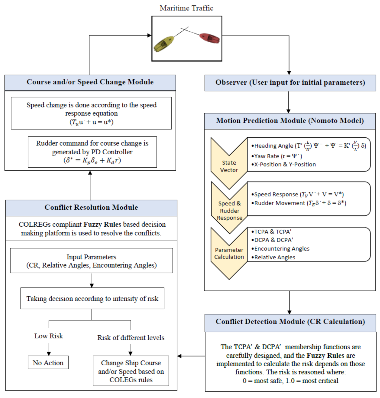
The whole process of collision avoidance system must go through five major components. These are (1) Extracting information from various sensors as an Observer to support other modules; (2) Predicting ship manoeuvring characteristics as a Ship Motion Prediction module; (3) Detecting Collision Risk (CR) quantitively as a Conflict Detection module; (4) Determining evasive solutions as a Conflict Resolution module, and (5) Implementing the solutions through actuators as a Course and Speed changing/keeping module. At this stage, this paper focuses mainly on the last four modules, i.e., Motion Prediction, Conflict Detection, Conflict Resolution, and Course and Speed keeping/changing module.
Ship motion prediction is a fundamental module for any collision avoidance system. This module is used to forecast the ships’ trajectories, and based on it, conflict detection and resolution are considered. In addition, this module also predicts the ship response for any change in the actuator command. As the collision avoidance is more on ship manoeuvring, only the planner motion, i.e., surge, sway, and yaw, are considered in this study. However, a detail on the motion models with 6 Degrees of Freedom (DOF) can be found in [5]. To predict the ship motion accurately, most researchers prefer to use the dynamic model in their proposed collision avoidance system by introducing the kinetics relations into a kinematic model. As most merchant ships are underactuated, some applications of dynamic model for collision avoidance systems can be found in the form of an underactuated model [6,7], where force is considered as an input or as a Mathematical Manoeuvring Groups (MMG) model [8], and the rudder angle and propeller revolution are considered as inputs to predict the ships’ manoeuvrability for distributed coordination. Since the ship dynamic models are complicated and the hydrodynamic coefficients are not readily available for different ships, this research employs a simplified dynamic model named as Nomoto model [9] or ‘rudder to yaw response model’. The Nomoto model can describe a ship’s rate-of-turn response to any given rudder angle macroscopically and is good enough for predicting ship motion with negligible variance in surge motion. To consider the variation in surge motion, a separate speed response equation is considered in this research.
After confirming the motion prediction module, next comes the Conflict detection module. This module allows the OOW to know when the evasion action needs to take. Mainly, the module contains a collision risk assessment, which triggers an event that requires humans to take action to avoid a collision. Expert-based method is one of the methods mostly preferred by researchers for detecting collision, where experts’ knowledge is fully utilized to assess the collision risk. There are two ways to utilize expert knowledge-Collision Risk Index (CRI) and Ship Domain (SD). The most popular way to get the CRI is to use Distance to Closest Point of Approach (DCPA) and Time to Closest Point of Approach (TCPA). Different researchers used different strategies to get this CRI value from DCPA and TCPA, such as Fuzzy theory [10], Probit regression [11], etc. Some believe that only DCPA and TCPA are not enough to define the risk entirely. Thus, more risk indicators (RI) are introduced in different articles such as relative distance, relative bearing and coefficient K are proposed by Yingjun et al. [12] for CRI calculation. On the other hand, Simsir et al. proposed ANN to use as a decision support system [13] for ship position forecasting and collision detection, whereas Deep Reinforcement Learning (DRL) and Artificial Potential Field (APF) based path planning strategy unified with COLREGs rules is proposed by Li et al. [14]. Few researchers have investigated the ship domain approach too, where the domain acts as a warning ring. More details of the ship domain can be found in [15].
This paper prefers the expert-based method over the model-based method due to its wide acceptability among different researchers and adaptability to the humans’ performance onboard. The expert-based method can replicate the belief of a group of experts and allow experts to share their experiences. To utilize the experts’ knowledge, the authors opt for the popular Fuzzy Logic and measure the Collision Risk (CR) for each ship involved in an encounter. The Closest Point of Approach (CPA) has been chosen, but, unlike others, while deriving the membership functions, non-dimensionalised DCPA (DPCA′) and non-dimensionalised TCPA (TCPA′) are used, where DCPA is divided by the largest ship’s length in an encounter to consider the effect of the ship size, and TCPA is divided by the largest ship length and multiplied by relative speed to take the influence of ship speed into account. In addition, considering the fact that the challenge to overcome any ship conflicts depends on the number of ships involved in that encounter, the Fuzzy membership functions are normalized by using scale factor (SF), where the SF can be tuned based on the expert choice to alter the risk value if necessary.
Once the conflict is detected, the next step is to find a reliable solution to avoid collisions. This conflict resolution module is the core of any collision prevention system. Many methods have been developed so far by different researchers in this regard. The rule-based method is one of those where a set of pre-set rules is used to avoid collisions. Naeem et al. [16] and Tam and Bucknall [17] used pre-set course change method, while Fang et al. [18] proposed to enlarge rudder angle until the trajectory is collision-free. Praczyk [19] mentioned Neural Network (NN) as a suggestion tool for rule-complaint actions, while Perera et al. [20] suggested Bayesian network for the same. The main advantage of this rule-based method is the COLREGs rules, and good seamanship can be treated in the rule system explicitly. However, many researchers believe that this cannot enumerate all the scenarios of multiple ship encounters. The virtual vector field method is another method where Artificial Potential Field (APF) [21,22] generates the repulsive potential around the obstacles and attractive potential to the destination. However, while using this method, the ship might trap in local minima, and ships’ dynamics are not taken fully into account. Discretizing the solution-space of the ship and choose the safest collision-free path with fixed control inputs is another way to resolve the ship conflicts issues. Benjamin [23] used optimization to get such collision-free solutions, while Szlapczynski [24] incorporated the ship domain approach with this method to make it more realistic. This method could consider the ship dynamics, but the calculation of input is time-consuming.
In general, the rule-based methods are simple and easy to define the COLREGs rules explicitly. Therefore, for the conflict resolution module, this research proposes a Fuzzy-logic based decision-making platform. Unlike others, instead of taking the decision based only on Collison Risk (CR), encountering and relative angles of each ship measured from others are also considered, and the corresponding membership functions are derived. This allows the system to consider all possible types of encounters and take decisions accordingly. COLREGs compliant rules are then implemented in the Fuzzy platform to take more realistic actions to avoid ship collision. To deal with multiple ship encounter, this paper proposes a simple but effective approach where each ship compares its evasive actions to avoid other existing ships, and the maximum-course and minimum-speed change approach is chosen in the decision-making process. By considering this approach, a ship would be able to satisfy all course changing requirements to avoid other ships. The ship also sacrifices its speed for a minimum time, allowing her to maintain its manoeuvrability while changing course. A conventional PD controller is then used to execute the command for course changing manoeuvre to take the appropriate rudder. The coefficients in the controller are tuned for each ship to ensure the minimum overshoot and less settle time. On the other hand, the speed change is considered by using a speed response equation. The information flow among the modules for the proposed collision avoidance system is given in Figure 1.
Simulations are done to justify the effectiveness of this novel collision avoidance system, and the ships are tested to avoid collisions in 22 complex scenarios named Imazu problem [25]. Some rather difficult situations of five ship encounters are also investigated, and the results are included in this paper. This paper is organized as follows: Section 2 explains the marine traffic rules and regulations and their importance in navigation. Section 3 includes a brief description of the mathematical model used for motion prediction. In Section 4, the Fuzzy-based conflict detection module is explained. Section 5 explains the core of the avoidance system, i.e., conflict resolution module for multiple ship encounters, and its execution. Section 6 shows the simulation results for the Imazu problems and other complex encountering situations. Finally, Section 7 concludes the overall findings and proposes some future works.

2. Marine Traffic Rules and Regulation

In marine traffic, all ships should abide by certain laws while trying to avoid collisions. These laws are formulated by International Maritime Organization (IMO) in 1972 and named International Regulations for Preventing Collisions at Sea (COLREGs). This 1972 convention [4] was designed to update and replace the Collision Regulations of 1960. The COLREGS includes 41 rules divided into six categories, which are: Part A (General), Part B (Steering and Sailing), Part C (Lights and Shapes), Part D (Sound and Light signals), Part E (Exemptions), and Part F (Verification of compliance with the provisions of the Convention). There are also four Annexes containing technical requirements concerning lights, sound signalling appliances, and additional signals for finishing vessels and international distress signals. However, this paper focuses only on Part B (Steering and sailing).
It is a matter of fact that several studies on ship collision avoidance systems have considered the COLREGs rule in their algorithm [26,27] and several ignore these completely [13]. A system ignoring the COLREGs rules might successfully avoid ship collisions. However, as the actions suggested by the resolution module violate the laws at sea, these are not acceptable in real practice. Statistics [28] reveal that 56% of major maritime collisions occur due to the violation of COLREGS rules. Therefore, it is crucial to choose an appropriate method for the collision avoidance system, which can incorporate the given rules appropriately. The terms ‘Give way’ and ‘Stand on’ ship are frequently used in the rules. According to the COLREGs, ships coming from starboard side are referred as ‘Stand on’ ship and have a higher priority for navigation. Thus, most of the time, the ‘Stand on’ ship keeps its original course and speed without any alteration. On the other hand, the ship coming from the port side is termed as ‘Give way’ ship. ‘Give way’ ship has less priority for navigator, and thus takes necessary actions to avoid the ‘Stand on’ ship.
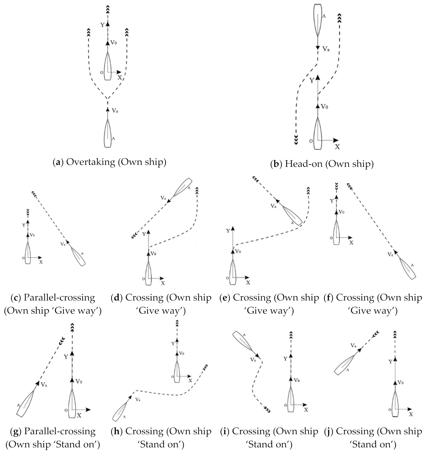
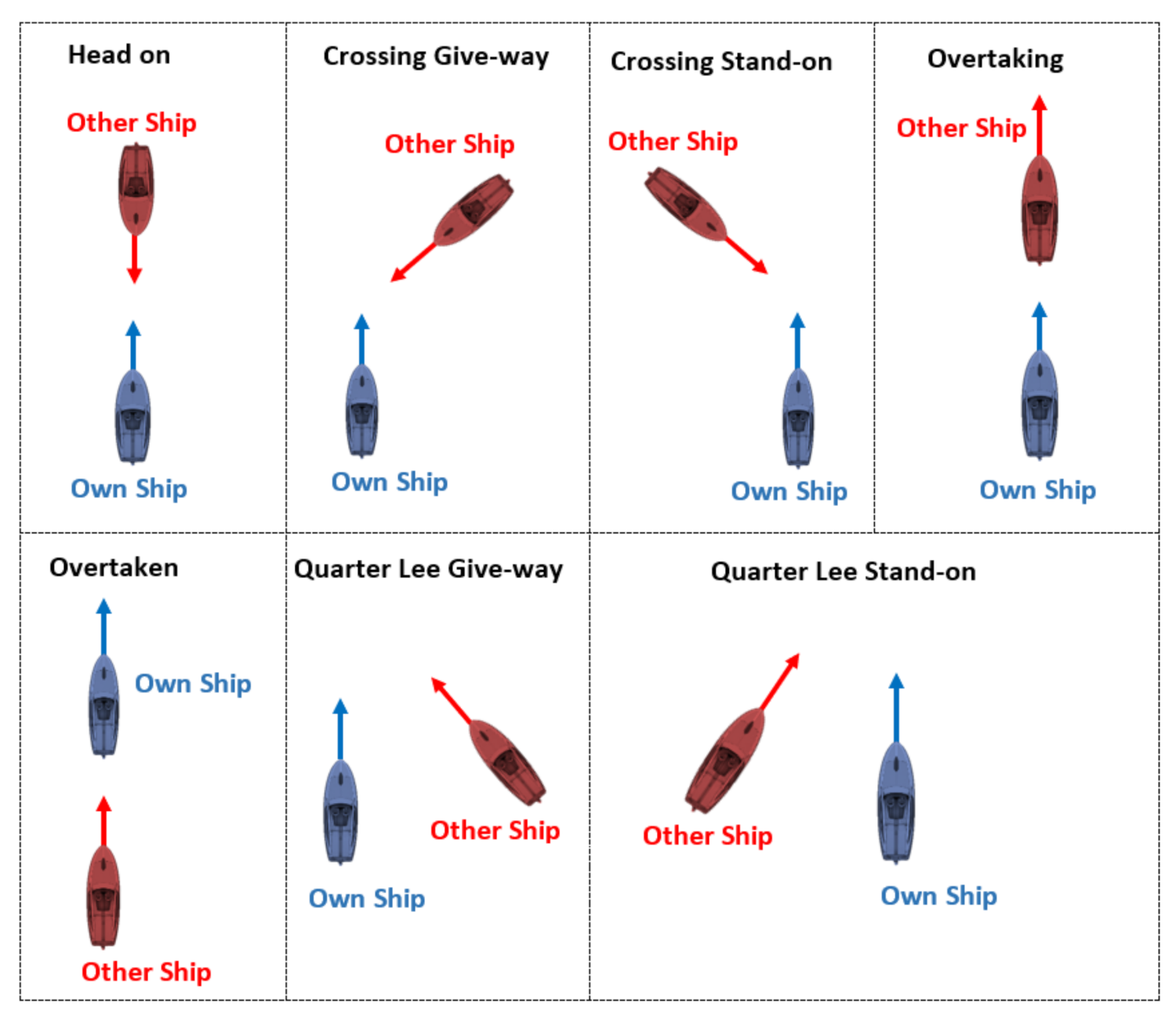
Maintaining a safe distance among the ships in marine traffic is paramount to enhance maritime safety. Therefore, COLREGs [rule 13(a)] emphasizes specifically maintaining a safe distance between two ships in overtaking and head-on situation. Such encountering situations are demonstrated in Figure 2a,b. Crossing an encounter of two ships is another situation that involves high risk. For this type of encounter, COLREGs mention the ships should take early actions to avoid situations of crossing ahead with the risk of collision in starboard to starboard and must be passing by port to port. Different crossing situations are mentioned in the COLREGs (rule 15). Figure 2c–f illustrates the crossing situations where the own ship is in a ‘Give way’ situation, whereas in Figure 2g–j, in ‘Stand on’ situation.
Although a ‘Stand on’ ship is believed not to take any action to avoid a collision, the statement is not always true. COLREGs rule 17(b) mentions that: “When, from any cause, the vessel required to keep her course and speed finds herself so close that collision cannot be avoided by the action of the “Give way” vessel alone, she shall take such action as will best aid to avoid a collision.” This means that if the ‘Give way’ ship does not take any appropriate actions to avoid the collision as required by the COLREGs rules, the ‘Stand on’ ship is forced to take appropriate actions to avoid a collision.
However, the actions taken by the ‘Stand on’ ship must be carefully formulated as there are no specific rules on it. In addition, COLREGs rule 8(b) mentions that: “Any alteration of course and/or speed to avoid collision shall if the circumstances of the case admit, be large enough to be readily apparent to another vessel observing visually or by radar; a succession of small alterations of course and/or speed should be avoided.” This rule highlights that the ship course and/or speed change in ocean navigation must be executed to avoid collision situations at any cost, and the action must be distinguishable by other ships.
Although these COLREGs rules are established in 1972, some issues hinder the practical implementation of the rules in ocean navigation. For example, all the rules are explained for two ship encounters. Therefore, in a multiple ship encounter, when a particular ship becomes both ‘Give way’ and ‘Stand on’ ship at the same time (when two other ships are approaching from its port and starboard side), COLREGs cannot give a solution. Additionally, when the ‘target ship’ (the ship that must be avoided in an encountering situation) has a very low or high speed compared to the ‘own ship’ (the ship that needs to take action to avoid the target ship), the rules become questionable. Therefore, in addition to the COLREGs rules, experts’ knowledge also needs to be considered to take the appropriate decision. Hence, this study proposes Fuzzy-logic based collision avoidance system, in which not only ‘Give way’ ships but ‘Stand on’ ships also take action if the risk becomes too high or unbearable.

3. Mathematical Model for Ship Motion Prediction

The motion prediction module is an integrated part of a collision-avoidance system that contains the process of predicting the trajectories of ships. When a ship encounters other ships, the system uses these forecasted trajectories to detect ship conflicts and decision-making. Therefore, the success of the whole system is very much related to the accuracy of the predicted trajectories. Researchers have found that the dynamic model [6,7,8] is the best to predict the ship motion as it considers the inertia effect and can predict the velocity change in hard manoeuvring. However, due to the complexity of the dynamic model, researchers prefer to use simplified models to design collision avoidance approaches, which are less precise but serve the purposes [29].

3.1. Prediction of Ship State

This research considers a first-order simplified response equation to describe the ships’ dynamics and assumes that the surge velocity is constant and there is no sway velocity. The coordinate system considered in this study to define the ship motion is given in Figure 3.
A similar model is also used by Fang et al. [18] and Liu et al. [30], which is known as ‘Nomoto model’, named after Nomoto. He has done this simplified ship dynamic approach and shown the following form of equations.
T ´ L U ψ ¨ + ψ ˙ = K ´ U L δ ψ ˙ = r x 0 ˙ = u c o s ψ v s i n ψ y 0 ˙ = u s i n ψ + v c o s ψ
where, L is the ship length, U is resultant ship speed, u is the surge speed, v is the sway speed, r is the yaw rate, ψ is the ship heading, δ is the rudder angle, K ´ = K L U is the non-dimensional steering gain, and T ´ = T U L is the non-dimensional time constant for yaw motion. The manoeuvring indices K and T for a particular ship can be calculated using its zigzag test results [31]. The smaller the value of T, the faster the ship will respond, and vice versa. Usually, the time constant of a ship is a time when the response reaches 63.21% of the target value. This paper adopts 20 ships data from the paper of Aulia [32], where the T value ranges from 33.36 to 418.60 s. Table 1 provides the necessary information for the 20 different ship types considered in this research.
MATLAB Simulink platform has been utilized to create the ship state subsystem in this study, and Equation (1) is solved numerically using Runge-Kutta method to get the state vector X = r ;   ψ ;   x ;   y for each time step for given rudder angle, δ .

3.2. Speed Response Model

Nomoto model assumes that the surge speed of a ship is unchanged, and the sway speed is zero. However, according to the COLREGs rules, a ship might need to change its speed to avoid collisions. Thus, this research considers the following speed response equation to predict the change in surge speed for any given command.
T U u ˙ + u = u *
The solution of the above speed response equation is given by:
u t = u 0 e t T u + u * 1 e t T u
where T U is the time constant for ship speed, u 0 is the initial speed, u * is the command speed, and u is the actual speed of a ship.
The value of T U is chosen so that it represents the time taken for a ship to reach 63.21% of this command speed. This can be proven by substituting t = T U in Equation (3). In addition, the study considers pure yaw motion while course changing, i.e., sway velocity is considered as zero.
MATLAB Simulink is used to model this speed response subsystem, and Equation (2) is solved together with Equation (1) using Runge-Kutta method.

3.3. Rudder Response Model

Like the speed response model, the rudder movement is predicted using a rudder response model, as given in Equation (4).
T E δ ˙ + δ = δ *
where T E is the rudder response time, δ * is the command rudder angle, and δ is the actual rudder angle.
Considering the δ 0 , the initial rudder as zero, the solution of the above rudder response equation is given by:
δ t = δ * 1 e t T E
In this study, T E is considered as 2.3 s as proposed by many other researchers to predict the rudder movement more realistically. Then the Equation (4) is solved in the Matlab Simulink platform together with Equations (1) and (2).

4. Module for Ship Conflict Detection

Either in a manned ship or unmanned ship, one essential module of a collision avoidance system is the conflict detection module, which assesses the collision risk and alerts the system to take evasive actions. This conflict detection module mostly assesses the risk based on answering the following three questions:
Question 1: Who are the potential threats in an encounter? (Detect the collision candidates)
Question 2: How far are the threats to collide? (Measure the distance to collide)
Question 3: At what time will they collide? (Measure the time to collide)
Many measures have been developed to answer the above questions. However, the Closest Point of Approach (CPA) concept is the most widely used approach both in the maritime and aviation industries [33]. In this CPA approach, two widely used indicators are Distance to CPA (DCPA) and Time to CPA (TCPA). The measure of DCPA answers Question 2, whereas TCPA answers Question 3. However, to get the answer to Question 1, different researchers proposed different strategies that utilities the values of DCPA and TCPA.

4.1. Selection of Risk Indicators for the Module

This research prefers the CPA approach to assess the risk. There are two major alternative methods available in this regard—model-based method and expert-based method—and this research opts for the latter due to its wide acceptability. Some researchers believed that solely DCPA and TPCA vales are not enough to calculate the risk, and, therefore, they have mentioned different risk indicators (RIs) [12]. Several studies carefully examine the other possible RIs to calculate the CR in a more realistic way and found that the ship length and relative speed are the most impactful parameters that can alter the CR drastically if not being considered while measuring the risk. Other parameters, such as relative angle, encountering angle, etc. are useful for decision-making process, not for CR measurement.
In this research, instead of treating the ship length, relative speed, DCPA, and TCPA independently while measuring the risk of ships in an encounter, nondimensional DCPA (DCPA′) and nondimensional TCPA (TCPA′) are used. In the nondimensional forms, the DCPA is divided by the maximum ship length in an encounter, and the TCPA is divided by the maximum ship length and multiplied by relative ship speed. This approach not only reduces the number of variables but also allows the module to fine-tune the risk measurement, especially for larger vessels.
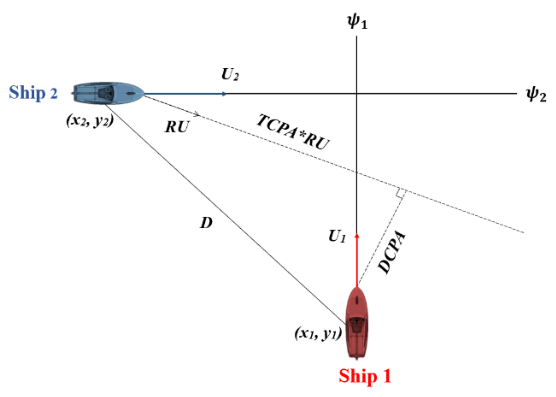
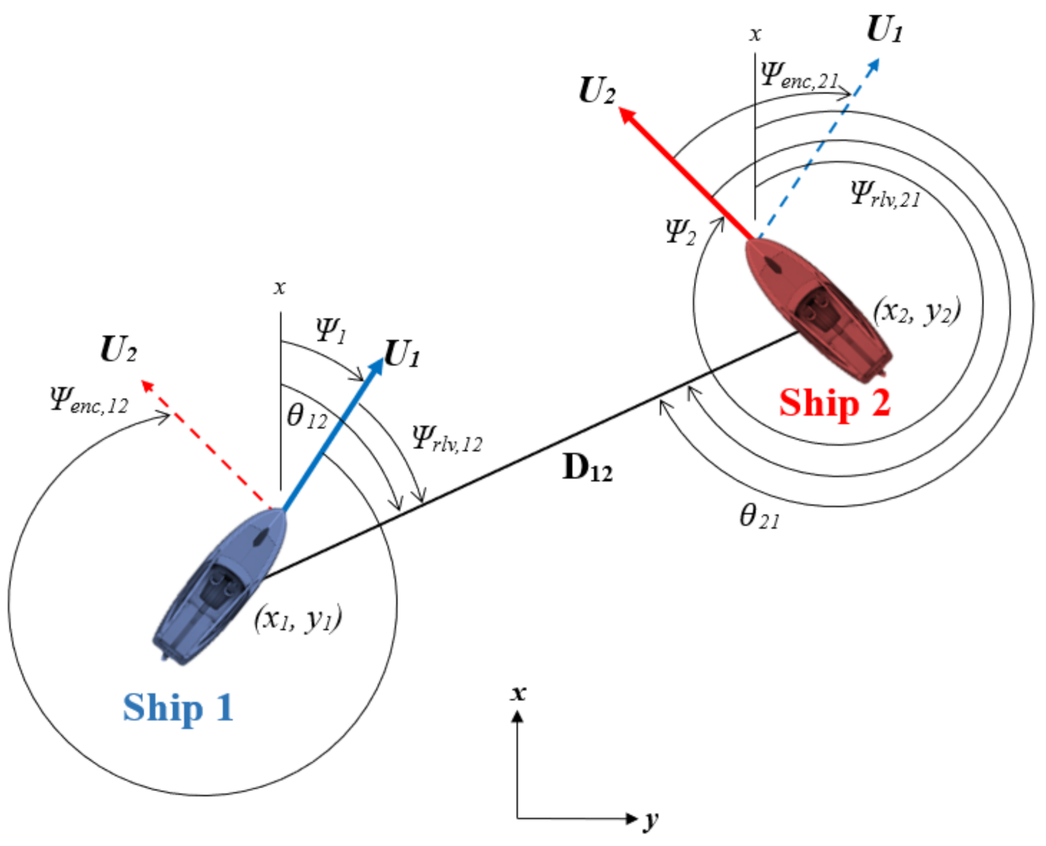
Figure 4 illustrates a two-ship encounter to help understand the DCPA and TCPA concept and their calculations, where U1, U2 are ship velocities, ψ 1 ,   ψ 2 are ship headings, (x1, y1), (x2, y2) are ship positions, D is the distance between the centroid of two ships, and RV is the relative velocity.
The values of DCPA and TCPA are directly related to the ship’s position, velocity, and course. If these values are known accurately, the following equations are used to calculate TCPA and DCPA.
R U x = U 2 sin ψ 2 U 1 sin ψ 1
R U y = U 2 cos ψ 2 U 1 cos ψ 1
R U = R U x 2 + R U y 2
T C P A = x 2 x 1 *   R U x + y 2 y 1 *   R V y   R U 2
D C P A = D 2 ( R V 2 * T C P A 2 )
The TCPA and DCPA are non-dimensionalised using the following equations where the largest ship size is considered in the denominator. By doing so, the D C P A and T C P A can be tuned, and so as the collision risk based on the largest ship size in any particular encounter. Otherwise, the system would consider the same risk for a ship when it meets ships of different sizes, which are not realistic.
D C P A = D C P A m a x L 1 ,   L 2
T C P A = T C P A * R U m a x L 1 ,   L 2
These D C P A and T C P A are dynamic and are always updated with the ship states. It is also mentioned that once a ship passes its CPA, T C P A turns to a negative value.

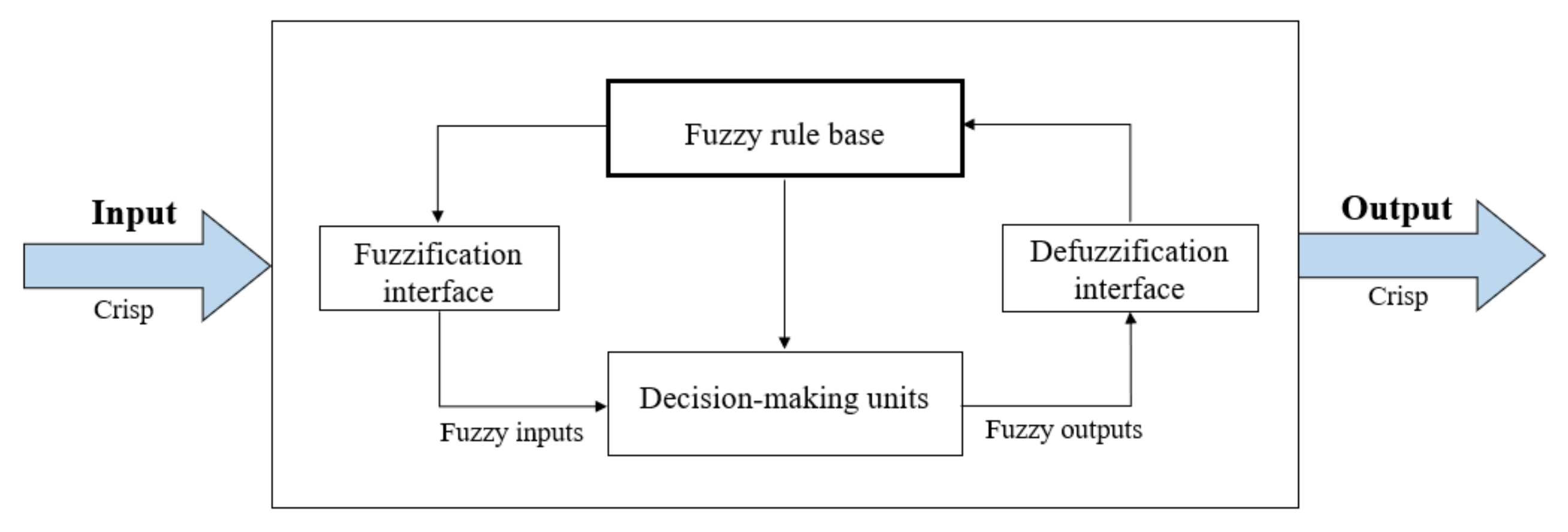
4.2. Fuzzy Inference System (FIS) to Measure CR

Fuzzy logic is a widely known method for decision making purposes [34,35]. Due to its ability to deal with the imprecision, i.e., uncertainly of human nature, and describe a system linguistically through rule statements, it gains its huge popularity. Fuzzy inference system (FIS) usually consists of four major components, which are: fuzzification of crisp inputs, construction of fuzzy rules, implementation of rules to get the fuzzy result, and at last, defuzzification of fuzzy result into a crisp output. This research uses the FIS to measures the CR for any given ship conflict. Figure 5 shows the framework of this system for better understanding. A detail of its four components is given in the following sub-sections.

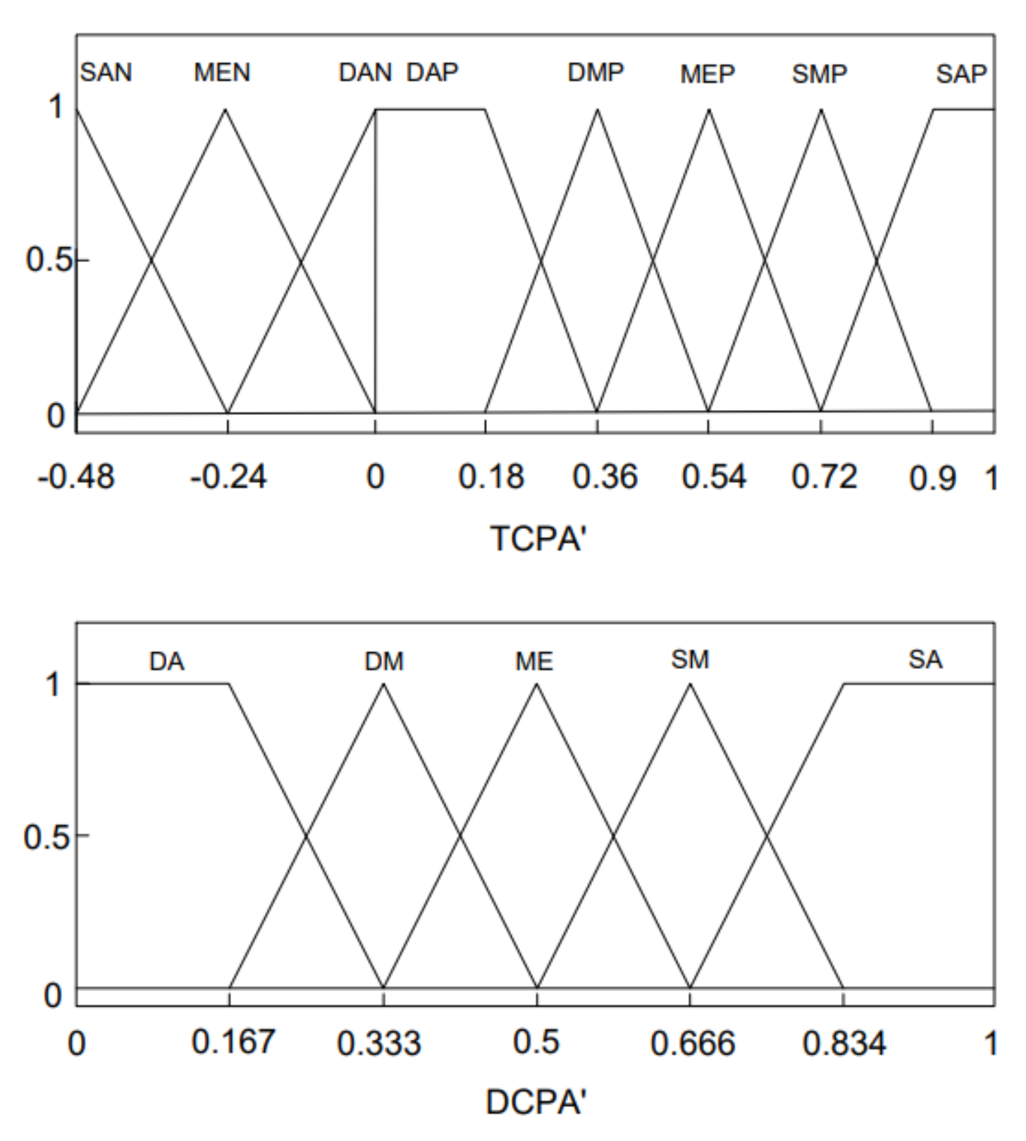
4.2.1. The Fuzzification Interface

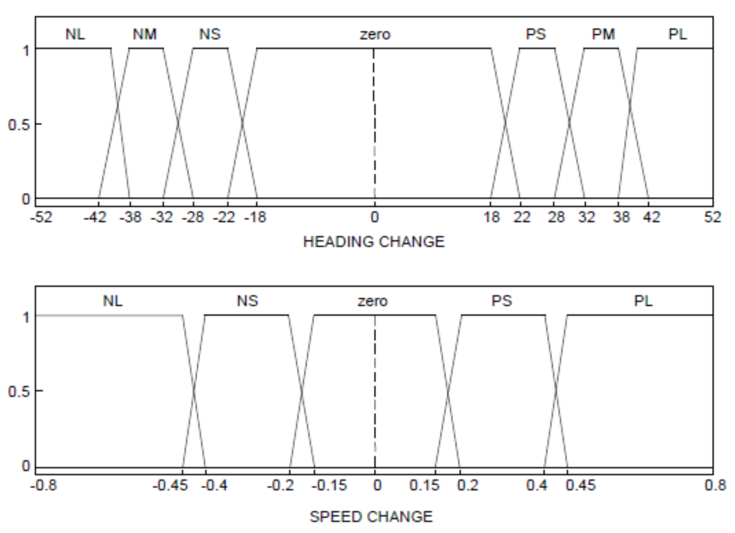
The main task of this interface is to map the crisp inputs from 0 to 1 by using a set of membership functions. Here, D C P A and T C P A are considered as two crisp inputs. Four and eight linguistic variables are considered and mapped carefully for D C P A and T C P A , respectively. The linguistics values used for D C P A are DA (danger advance), DM (danger medium), ME (medium), SM (safe medium), and SA (safe advance), and for T C P A are SAN (safe advance negative), MEN (medium negative), DAN (danger advance negative), DAP (danger advance positive), DMP (danger medium positive), MEP (medium positive), SMP (safe medium positive), and SAP (safe advance positive). For a fixed set of membership functions and a given set of inputs, the system is then designed to calculate the CR as per defined rules. The rules are prepared based on expert knowledge, which is, if D C P A and T C P A are small, CR is big, and vice versa. However, it is believed that CR should be higher for the same set of D C P A and T C P A , if the encountering situation involved more than two ships. Therefore, an adaptive membership function is necessary to consider the effect of different numbers of ships in an encounter. In this regard, this study considers the scale factor (SF) to normalise the maximum value of the mapping. The user can tune this SF value as per need. Usually, for a higher number of ships encounter, an increase in SF value results in a higher value of CR, thus raising the level of awareness of the situation.
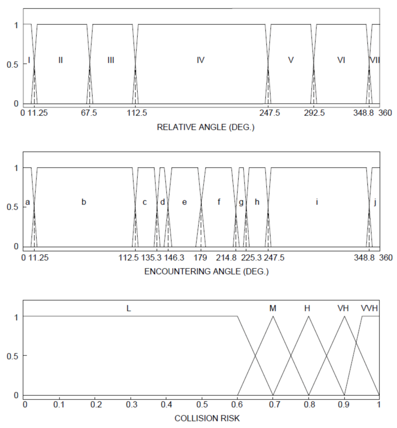
MATLAB Fuzzy Toolbox is used to create the memberships for D C P A and T C P A as shown in Figure 6.
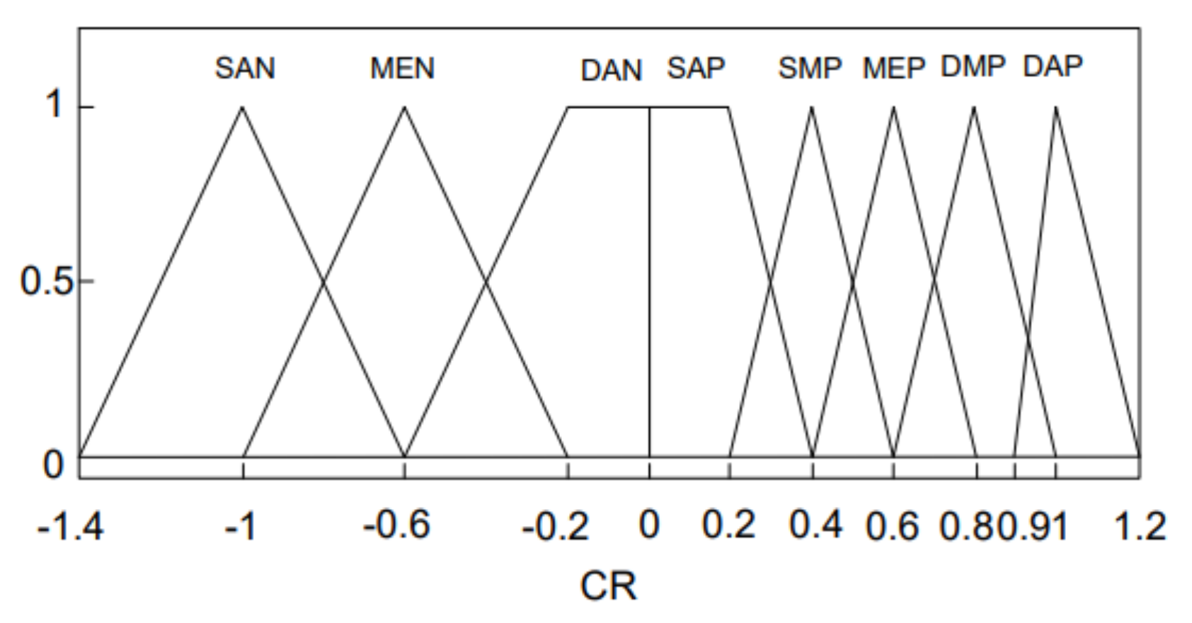
For the output, eight linguistic variables are considered and mapped for CR. The negative value of CR means that the risk has just passed, whereas zero means no risk and 1 means the highest risk. Figure 7 shows the membership function used for measuring CR.
The membership function for CR is used for defuzzification, i.e., to convert the fuzzy output to a crisp output.

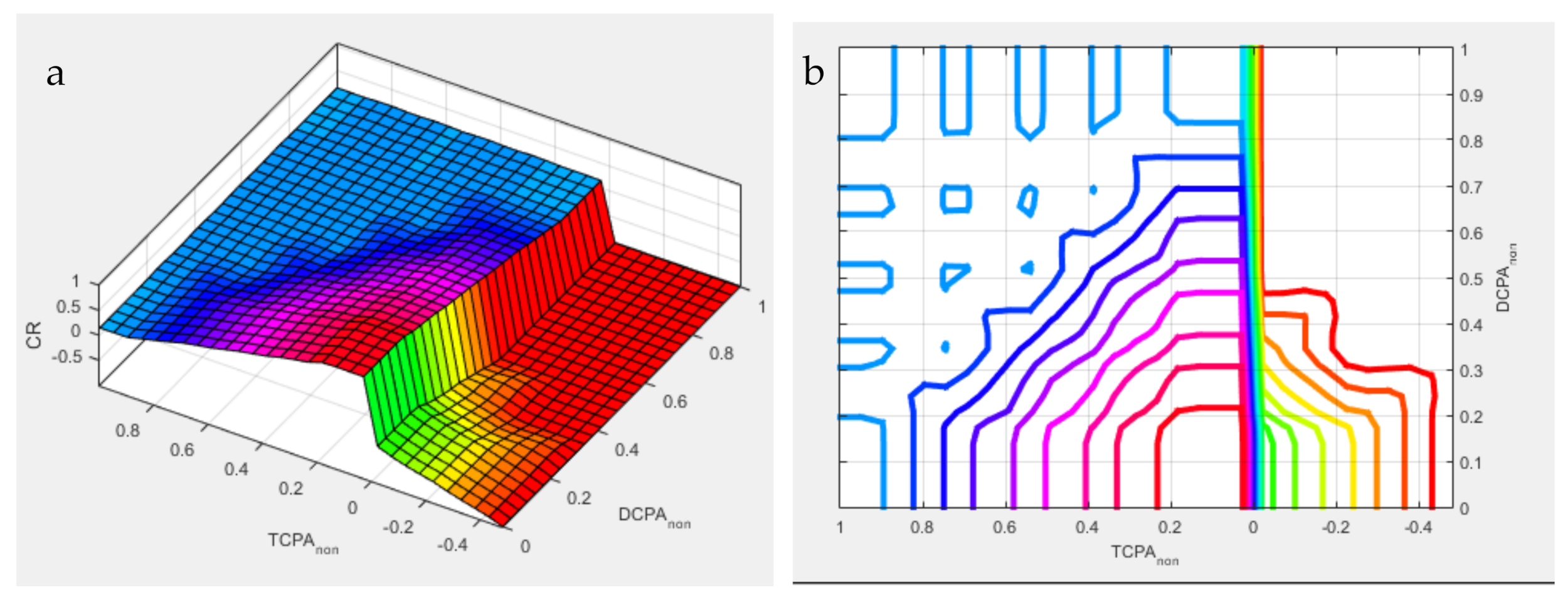
4.2.2. Fuzzy Rule Base

A series of linguistic statements or rules are defined in the FIS system to calculate the CR based on D C P A and T C P A . In order to reason the value of CR, the fuzzy rules are expressed in the form of IF-THEN to describe the relationships between the inputs and output. The rules are defined in the MATLAB Fuzzy Toolbox platform and shown in Table 2.
A 3D surface plot of the rules is shown on the left side of Figure 8, which indicates that CR is high when the D C P A and T C P A are small. Additionally, the right side of Figure 8 demonstrates the contour map for rules.

4.2.3. Decision Making Units

There are two widely known inference methods in the FIS. These are Mamdani’s fuzzy inference method and Takagi-Sugeno’s fuzzy inference method. The first two parts of the Mamdani and Sugeno type FIS, i.e., fuzzifying the inputs and applying the fuzzy rules, are exactly the same. The main difference between these two FISs is that Sugeno output membership functions are either linear or constant. On the other hand, in Mamdani FIS, the output of each rule can be a fuzzy logic set. Thus, the Mamdani type is intuitive and well suited to human input. Therefore, Mamdani type is adopted in this research as this study involves human experience sharing for collision risk calculation.

4.2.4. Defuzzification Interface

Defuzzification is needed for Mamdani type FIS. This is the step to convert the fuzzy output to a crisp output. MATLAB Fuzzy logic toolbox supports five built-in methods for the defuzzification process. These are Centroid, Bisector, Middle of Maximum (MOM), Smallest of Maximum (SOM), and Largest of Maximum (LOM). This study chooses centroid defuzzification method that returns the centre of gravity of the fuzzy set along x-axis. The centroid is computed using the following formula
X C e n t r o i d = i μ x i x i i μ x i
where μ x i is the membership value for point x i in the universe of discourse.

5. Module for Conflicts Resolution and Execution

In recent years, many techniques have been proposed for solving collision avoidance problems. These techniques have implemented many rules when deciding the evasion actions to avoid a collision. However, the development of a completely COLREGs rules compliant system is still blank. Some researchers used some popular rules, such as Rule 6, 8, 13–19, in their algorithm. However, these rules address the obligations of ships in two ship encounters; thus, choosing the most suitable rule is difficult for multiple ship encounters. In addition, the COLREGs rules are written for the OOWs in human language [36], which does not have any quantifying information for execution. Additionally, the ship is asked to keep at a safe speed or distance, while the values of the safe speed and distance are not addressed in the rules. Therefore, compliance with COLREGs rules strongly depends on experts’ knowledge and good seamanship [37]. This research shows the effort of interpreting the COLREGs rules in various encountering situations through a Fuzzy logic-based decision-making platform.

5.1. Selection of Inputs for Fuzzy Based Decision Making System

Considering appropriate and impactful input parameters for a FIS while taking evasion actions for collision avoidance is very crucial. Perara et al. [38] considered four inputs, namely, collision distance, collision region, relative speed ratios, and relative collision angle to define the corresponding membership functions. The decision was made based on the defined fuzzy rules without considering the collision risk (CR) separately. On the contrary, in this study, CR is considered as one of the prime inputs for decision making, which is available from the conflict detection module where the TCPA, DCPA, ship size and relative velocity effects are already taken into account. In addition, to implement the COLREGs rules, encountering and relative angles are considered (which defines the encountering types) together with CR for the decision-making process.
Figure 9 illustrates the encountering and relative angle in a two-ship encounter, where D12 is the distance between ship 1 and ship 2, U1 and U2 are the velocities of ship 1 and ship 2, ψ 1 and ψ 2 are the headings of ship 1 and ship 2, θ 12 is the angle that the line joining ship 1 and ship 2 makes from the north of ship 1, θ 21 is angle that the line joining ship 1 and ship 2 makes from the north of ship 2, ψ r l v , 12 is the relative angle of ship 2 measured from ship 1 bow, ψ r l v , 21 is the relative angle of ship 1 measured from ship 2 bow, ψ e n c , 12 is the encountering angle of ship 2 measured from ship 1, and ψ e n c , 21 is the encountering angle of ship 1 measures from ship 2.
The following set of equations is used to calculate the encountering and relative angle of ship 2 measured from ship 1.
θ 12 = a t a n 2 x 2 x 1 , y 2 y 1 Ψ r l v , 12 = θ 12 Ψ 1 d e t 12 = U 2 sin Ψ 2 * U 1 cos   Ψ 1 U 1 sin   Ψ 1 *   U 2 cos   Ψ 2 p r o d 12 = U 2   sin   Ψ 2 *   U 1   sin   Ψ 1 + U 2   cos   Ψ 2 * U 1 cos   Ψ 1 Ψ e n c , 12 = π + a t a n 2 d e t 12 , p r o d 12    
Here, θ 12 and Ψ r l v , 12 need to be positive to calculate the encountering and relative angle accurately. If θ 12 and Ψ r l v , 12 become negative, 2π is added to the parameters to make these positive again. Similar set of equations is used to calculate the corresponding angles of any ship measured from others.

5.2. Calculation of Encountering Type

Encountering type can be identified by using the encountering and relative angle of each ship measured from others. In this study, the surrounding of each ship is divided into 7 zones based on the relative angles, and for each zone, the encountering types are defined based on the encountering angles. Figure 10 shows the 7 different encountering types identified in this research. These encountering types are then marked based on the relative and encountering angle, as shown in Figure 11. This figure is then used to define the COLREGs Fuzzy compliant rules, and the actions are taken based on experts’ knowledge.

5.3. Fuzzy Inference System (FIS) for Decision Making

In order to map the crisp inputs to fuzzy inputs, membership functions are designed for relative angle, encountering angle, and collision risk. Considering Figure 11, seven and ten linguistic variables are defined and mapped for relative and encountering angle, respectively. On the other hand, five variables are considered for CR to map the risk value. MATLAB Fuzzy Toolbox is used to create the membership functions as shown in Figure 12.
The decisions are made either by changing the course or changing speed or changing both simultaneously. Seven and five linguistic variables are considered and mapped to define the membership functions for the course and percentage of speed change, respectively, and shown in Figure 13. These membership functions are used for defuzzification, i.e., to convert the fuzzy outputs to crisp outputs.
Fuzzy rules are defined according to the COLREGs rules. These relative and encountering angles in a ship encounter enable the fuzzy system to distinguish the give-way and stand-on ships, and then, actions are taken based on the CR values. The actions are reasoned as large values so that it is distinguishable by other ships. Moreover, if the actions taken by the give-way ships are not enough to reduce risk, the stand on ships are also reasoned to take adequate actions to avoid a collision. In this study, CR > 0.9 is defined as this very-very high (VVH) risky situation, and once it reaches a critical point, the stand-on ships are allowed to take action together with the give-away ships. It is mentioned that although the membership functions for heading and speed change contain both positive and negative values, at this stage, port side turning and increase of speed are avoided while defining the fuzzy rules. Table 3 shows the Fuzzy rules considered in the FIS as a decision-making platform.

5.4. Decision Making for Multiple Ship Encounters

This study considers many-to-many situations where each ship is allowed to take action depending on others’ actions. It is based on the assumption that the ships can exchange their state information via a communication or coordination structure. In a multiple ship encounter, the proposed FIS calculates the possible avoiding action for each ship to avoid others. Since the actions are different from avoiding different ships in an encounter, a ship always has more than one option to avoid the collision. In such a situation, this research proposes to compare the available options for each time step and considers the largest course change and the smallest speed change option as an overall action to avoid its surrounded ships. To understand this approach, let us consider a three-ship encountering situation, where the FIS calculates for Ship 1 to take 150 to avoid ship 2 and 450 to avoid ship 3. In this situation, if ship 1 takes 150 to avoid ship 1, it might collide with ship 2. However, if it takes 450 to avoid ship 2 as a maximum course changing approach, it already covers the requirement to avoid ship 1. On the other hand, as reductions in speed decrease a ship’s manoeuvrability, this study prefers a minimum speed reduction approach for multiple ship encounters to allow the ship to consider maximum course change without sacrificing its manoeuvrability. Figure 14 demonstrates a similar three-ship encountering situation, where each ship has two options to avoid the other two ships. Therefore, based on maximum-course and minimum-speed change, the decisions are taken for each ship to avoid others.
This unique maximum-course and minimum-speed-change approach for decision making approach has been found to be effective and tested for complicated multiple ship encounters. The results are included in Section 6.

5.5. Implementing FIS Decisions to the Ship Sytem

As a conflict resolution model, in this study, the FIS is designed to choose whether to alter course or speed or both simultaneously based on the dynamic CR, encountering and relative angle of each ship measured from others. To consider the speed change, the speed response model as mentioned in Section 3.2 is used.
On the other hand, to take an appropriate rudder angle for any given course alteration, a conventional Proportional-Derivative (PD) feedback controller is used as shown in Equation (15).
δ * = K P ψ e r r o r + K D r
where δ * is the command rudder, ψ e r r o r is the heading error, i.e., the difference between the actual and command heading, r is the yaw rate, K P is the proportional gain, and K D is the differential gain.
The FIS is designed to take maximum 45 ° course change at highest risk, and a ship is capable of taking maximum 35 ° rudder to alter its course. Based on these two facts, the value of K P is tuned and selected. On the other hand, K D is tuned for each ship based on its response rate and minimizes overshoot and settling time while taking the rudder. Figure 15 shows a typical layout of a PD controller used in this study.
In this study, as developing the PD controller is not the main concern, the trial-and-error process is adopted to tune the values. These pre-selected K P and K D values are then used in Equation (15) to get the rudder command for any given course changing manoeuvring.

6. Results and Discussion

The integrity of the developed modules for the proposed collision avoidance system is tested for ships in different encountering situations. Initially, two ship encountering situations are examined. Following that, the system is tested for a maximum of five ship encounters. The proposed system is also investigated for different ships with different manoeuvring characteristics, ship size, and speed. Finally, Imuzu-proposed 22-cases [25] are taken into account to analyse the complex situations, and collision avoidance for each case is successfully demonstrated.

6.1. Integrity Check for All Modules

A sample two-ship encounter simulation is considered to check the integrity of all modules, i.e., how the modules all work together within the proposed collision avoidance system. In this study, for two ship encounters, the scale factors (SFs) for D C P A and T C P A are considered as 20 and 180, respectively. These SFs can alter the degree of risk considered by the system for a given condition, thus controlling the timing to initiate the evasion actions in the conflict resolution module. In addition, these SFs can also help the OOW to decide the minimum safety distance that he would like to consider while passing other ships. To get these SFs optimally could be a future scope of this research. However, for simplicity, at this stage, the factors are tuned manually to ensure all ships with different sizes could avoid each other with some reasonable safety margin, which is higher for big ships, and vice versa.
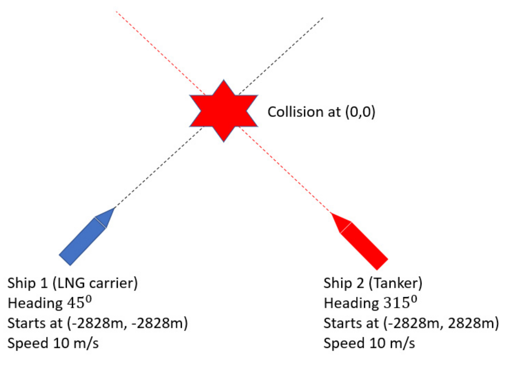
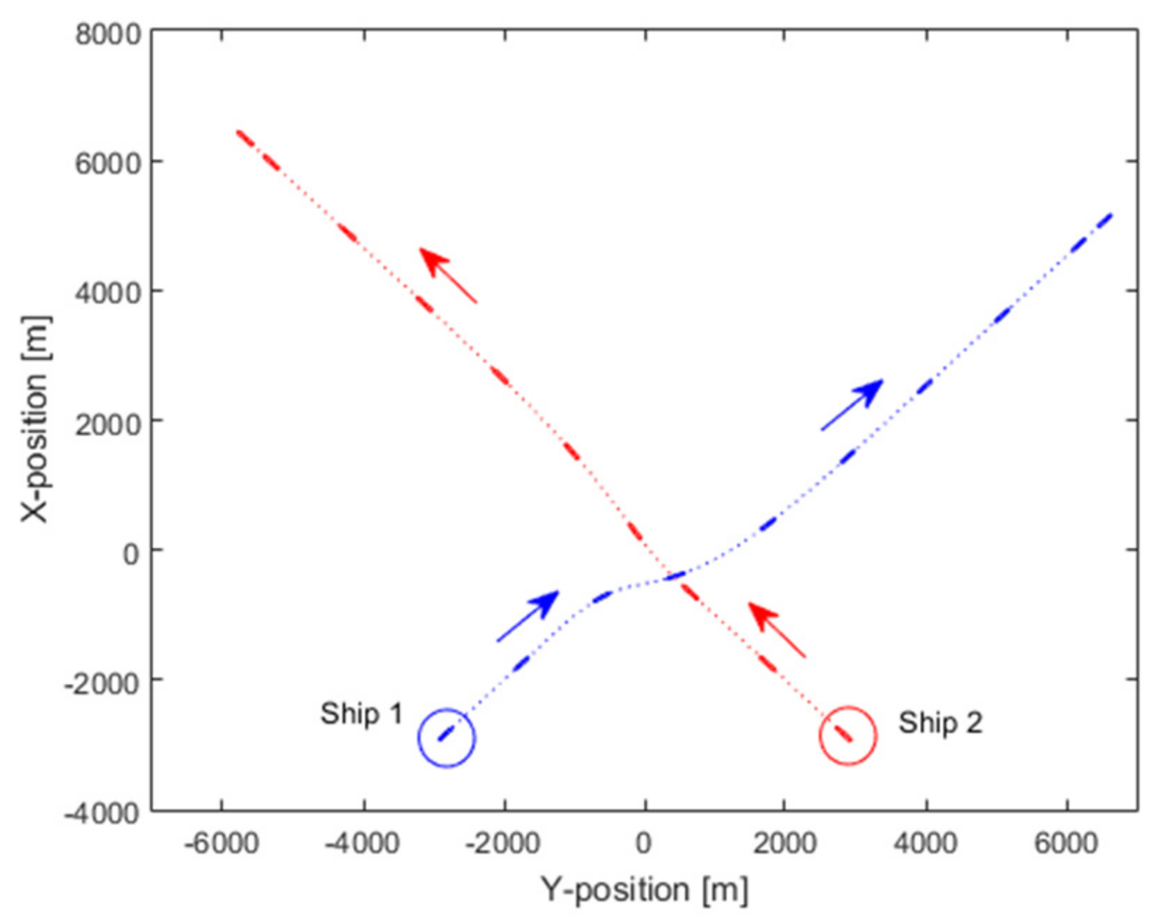
The system starts with a realization of the ships’ initial states, which are given as user inputs. Two ships, 270.11 m LNG carrier (noted as Ship 1) and 304.65 m Tanker (noted as Ship 2), are selected for a collision course as shown in Figure 16. The initial headings and positions for these two ships are chosen to ensure a collision at (0, 0) point in the simulation domain if the ships are not taking any avoiding action. The simulation is then run for the aforementioned two ship encounter, and a successful demonstration of the avoiding action is illustrated in Figure 17, where the ships are plotted at a 300 s timestamp.
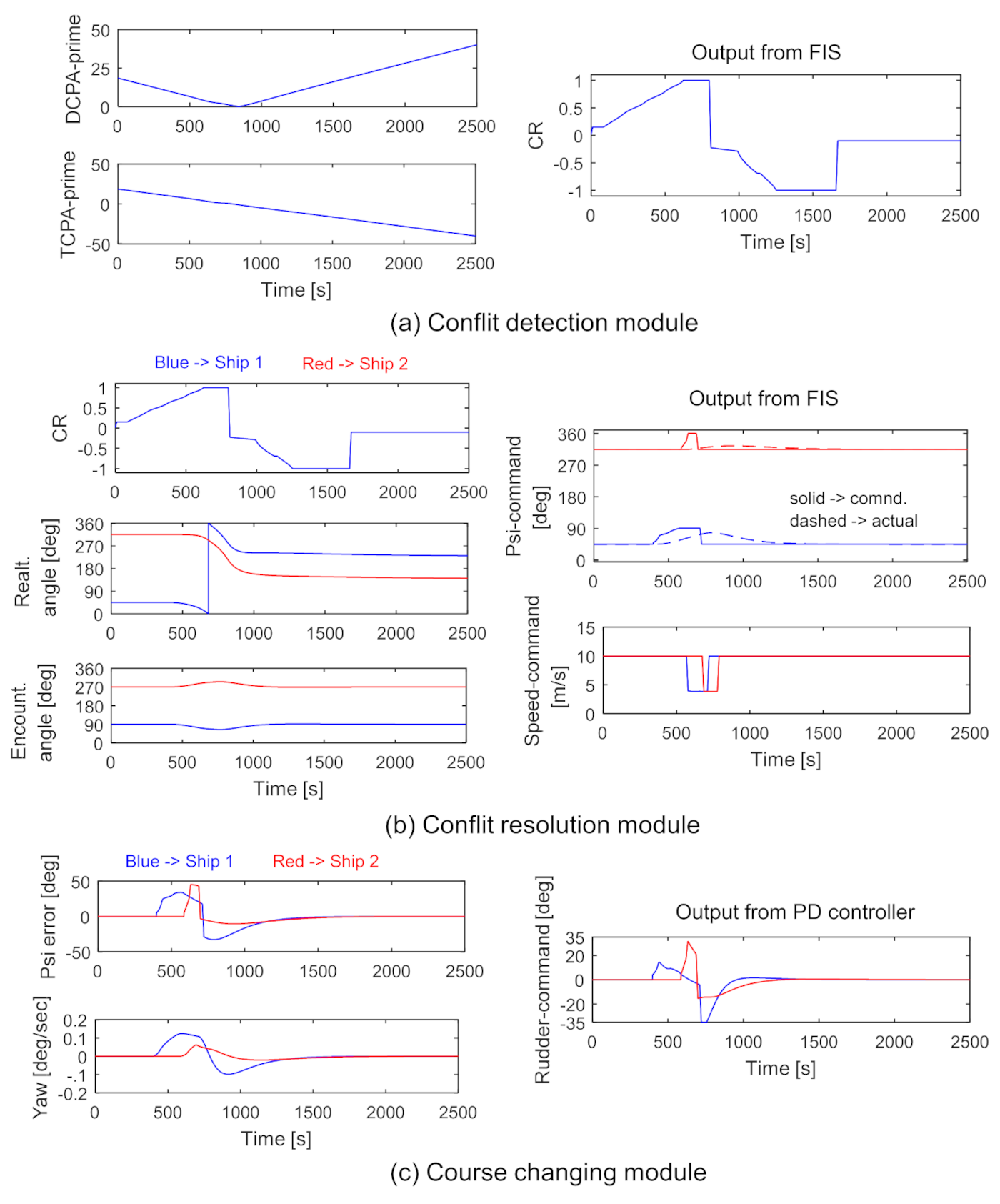
Figure 18 presents a detail of various inputs and outputs of different modules to know how the module works within the system. Here, D C P A and T C P A are calculated within the conflict detention module based on the user-defined initial conditions. These values are then scaled according to the scale factors, which is 20 for D C P A and 180 for T C P A for two-ship encounters. These scaled values are mapped to the D C P A and T C P A fuzzy membership function within the FIS, and the CR is calculated accordingly based on the defined rules. Figure 17 shows that the initial risk (CR) is 0.01 as the ships are quite far from each other. This CR and the calculated relative and encountering angle of each ship are then fed to the conflict resolution module for decision making process. Here, while taking the decision, CR is the same for both ships. However, the relative and encountering angle of ship 2 measured from ship 1 are 45 ° and 90 ° , whereas the same for ship 1 measured from ship 2 are 315 ° and 275 ° . By this way, the FIS could detect the give-way and stand-on ship and take the decision according to the COLREGs rules. In this case, ship 1 is a give way ship, whereas ship 2 is a stand on. Initially, when the CR is very low, no action is taken by the system for ship 1. However, when the CR gradually increases to 0.65, at 399 s, the module starts to order heading-change to starboard side. It starts with an angle calculated by FIS, which is updated up to 90 ° (initial + 45 ° ) later as the CR reaches 0.89. It is mentioned that even though the system commands a particular heading for different ships, the actual heading for the same command would be different for different ships. It is usual that a big ship responds slower than a small ship due to its large mass, i.e., greater inertia force. It also depends on ships’ manoeuvring characteristic. The command heading and the actual heading are plotted together in Figure 18 to understand the differences. In the case of ship 1, although the course changing command is set to 90 ° , the actual course change is 76.8 ° and there is a time lag to attain that course. Now, after the 90 ° course command for ship 1, as the CR kept increasing, the module considers it as an extremely high-risk situation and initiates the speed reduction command at 570 s when the CR is 0.90. As the CR kept increasing even after these actions, the system finally commands the stand on ship (Ship 2) to alter its curse to 360 ° (initial+ 45 ° ) and decreases its speed at a later stage. In this avoiding process, the actual course change for ship 2 was only 324 ° due to its large inertia force. Finally, both ships avoid each other at 814 s with a safety margin of 498 m.
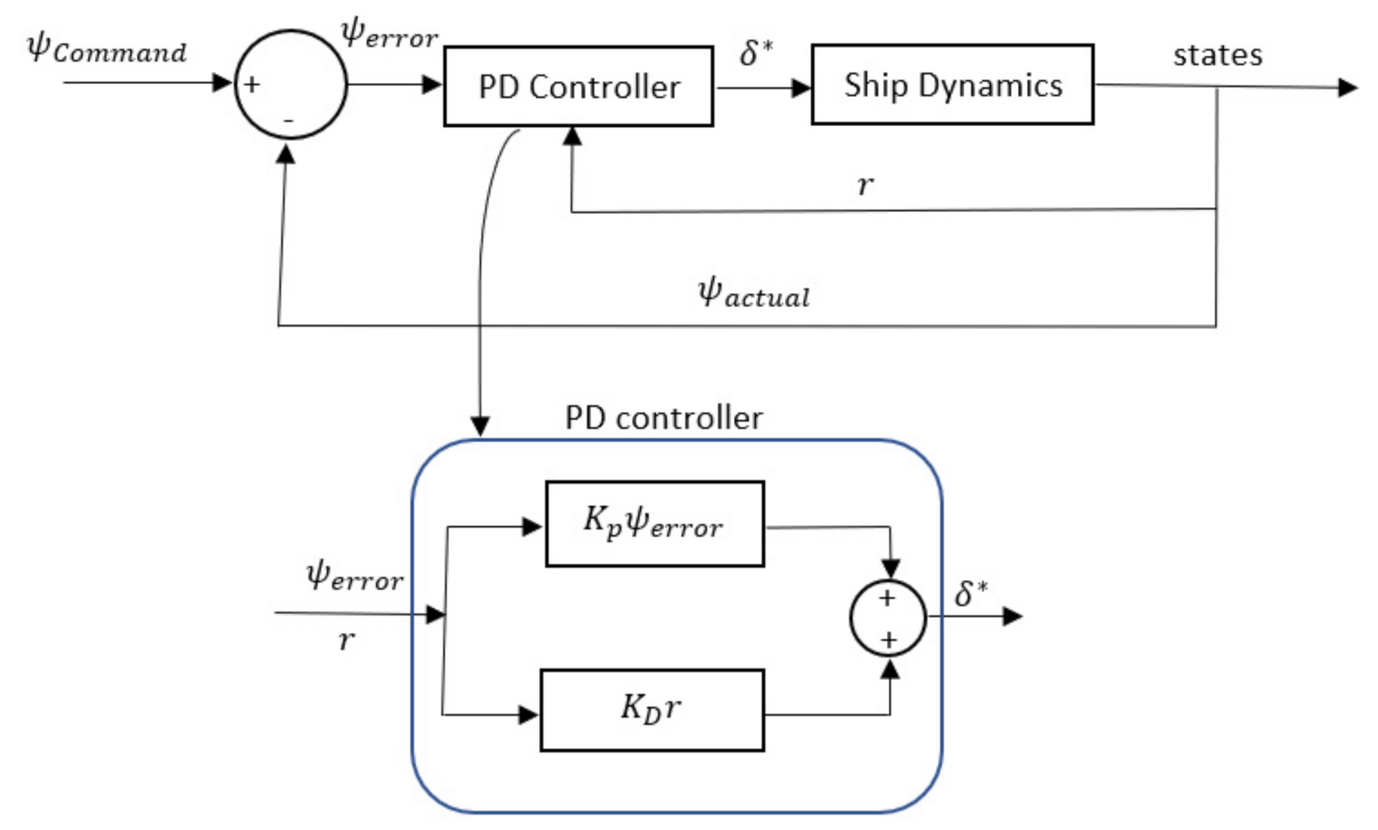
During the course alteration, as mentioned in Section 5.5., PD controller is used. The heading error and the yaw rate of each ship are fed into the controller, and the rudder command angle is calculated to put it as an input for the motion prediction module. A simple demonstration of this module is also shown at the lower part of Figure 18, where ± 35 ° rudder is considered as a max-min limit for the controller to take.

6.2. Verifying the System for Different Ship Types and Speeds

Two ship encountering situations are considered at the initial stage of this study to judge the feasibility of the proposed collision avoiding system. The verification is done on how the system copes with different types of ships and their corresponding speeds. Most of the published articles on collision avoidance systems concluded their work based on their preferred ship types. They barely judge their systems for different ship types and speeds. Therefore, this study would like to take the opportunity to check how the system reacts for different ship types and speeds.

6.2.1. The Proposed System for Different Ship Types

There are 20 different ships considered in this study, as shown in Table 1. This ranges from 43.26 m (Harbour tug) to 409.59 m (Tanker). Three different cases are investigated for different ship types, while the initial speeds, headings, and positions are kept the same. Table 4 lists up the details of the ships considered in these three case studies.
Although the ships are started from the same initial states in the three cases, the CRs are expected to be calculated differently by the conflict resolution module due to different ship sizes. On the other hand, as these ships have different response rates, the conflict resolution module should also adjust the evasive actions taken by the ships depending on their dynamic response.
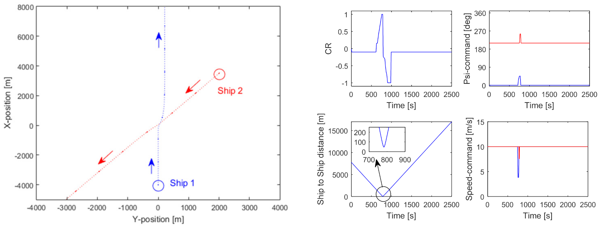
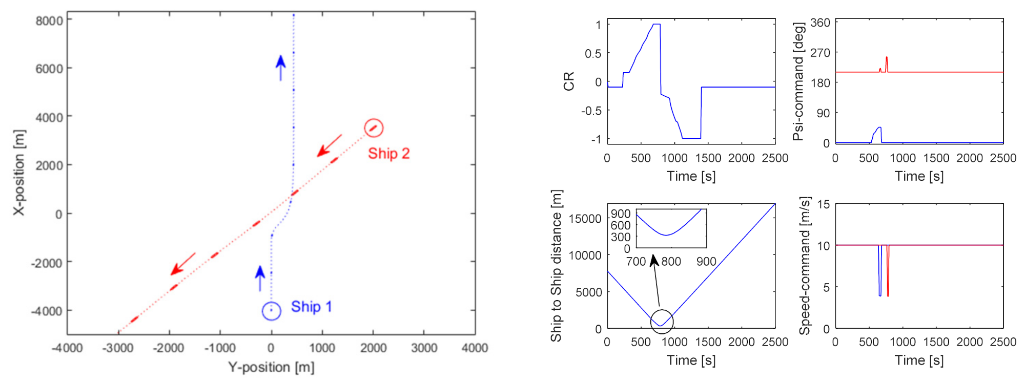
Figure 19, Figure 20 and Figure 21 illustrates these three cases mentioned in Table 4. For the given initial conditions, the conflict detection module considers no risk in case 1 and case 2, as the CR is less than 0, whereas, in case 3, the module considers the ships are at low risk with CR = 0.18. Later, with the time-lapse, the CR starts to increase for all three cases. However, in case 1, the module initiates the evasive action at 713 s, when the CR reaches approx. 0.65, whereas in case 2, it is at 532 s. This is because the CR reaches its medium-range value earlier in case 2 as it involves larger ships. On the other hand, case 3 involves two large ships, and the module initiated the course changing at 348 s, which is the quickest if compared with the other two cases. It demonstrates that the module has the ability to tune the risk factor, thus the timing to initiate the avoiding actions depending on the ship size. In addition, the duration while persistently holding the command for heading or speed change is not the same for the three cases. In case 3, it is much longer than case 2 and case 1. This is because a larger ship requires more time for a given course or speed change due to its larger inertia. It is also noted that the minimum ship-to-ship distance while the ships crossing each other are 48 m, 324 m, 505 m for cases 1, 2, and 3, respectively.

6.2.2. The Proposed System for Different Ship Speed

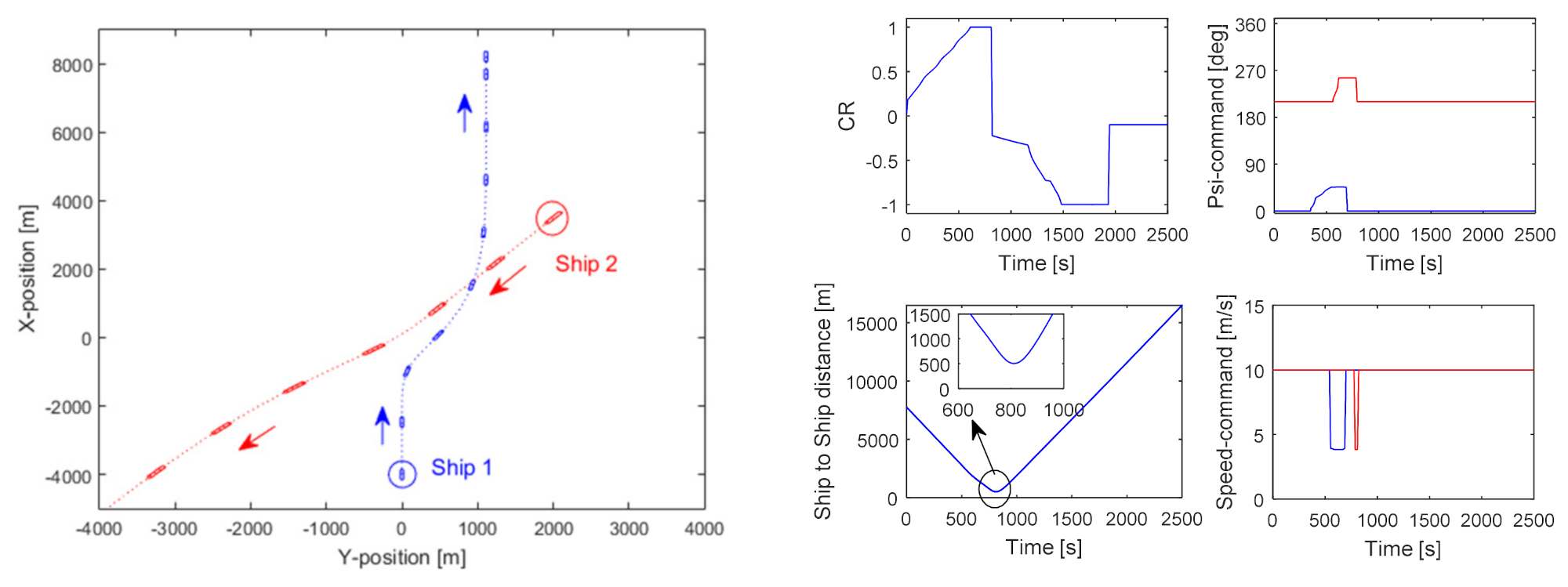
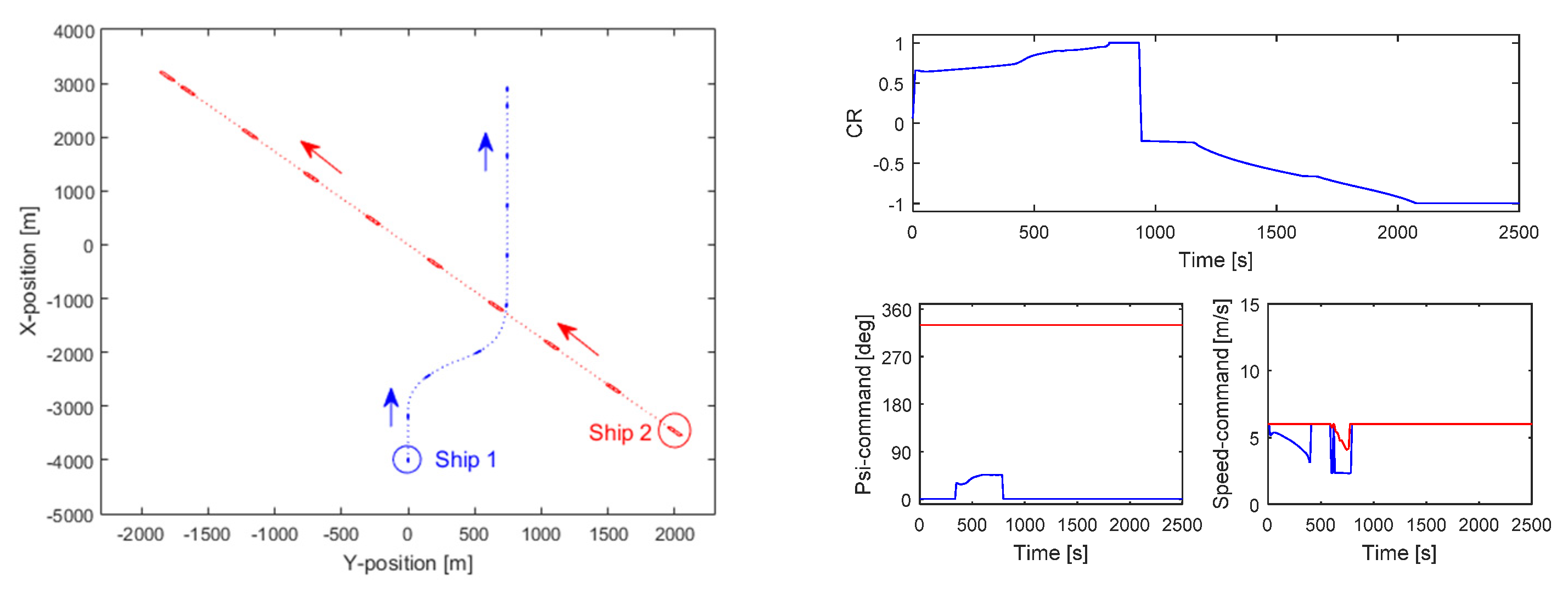
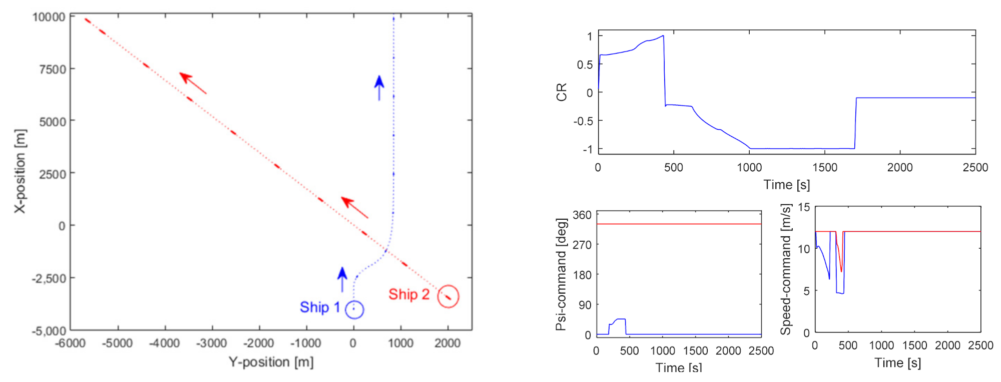
The system is tested for different ship speeds while keeping the ship length and the other initial conditions the same, and the ship responds differently at different speeds, demonstrating that the system can cope with that dynamic behaviour by adjusting the timing and duration of the ship evasive actions. Table 5 lists up the details of the ships considered in the following case studies.
Two crossing cases are investigated for the same ship and initial conditions but with different speeds. Figure 22 and Figure 23 illustrate the two cases mentioned in Table 5.
CRs for the above two cases are similar in nature. However, the graph is stretched in case 1 as the ships run slowly. In both cases, ship 2 (stand-on ship) maintains its course with a slight reduction in speed at the later stage when the CR attains its maximum peak. In addition, the duration while considering the course change for ship 1 is shorter in case 2 because the ships responded quickly due to having higher speed. It is also evident that the trajectories for both cases are almost identical. This means that the system has the ability to take adequate actions to guide a ship in a collision-free path, even if the speed varies.

6.3. Maximum-Course and Minimum-Speed Change Approach for Multiple-Ship Encounters

Very few researchers have attempted to verify their proposed collision avoidance system for multiple-ship encounters. A literature review revealed that existing multiple ships encounters collision avoidance models either ignore the COLREGs rules or used a pre-planned or optimization path without taking ship manoeuvrability into account. Therefore, those actions are not realistic. On the contrary, this study considers ship manoeuvring indices, i.e., K and T for 20 different ships in the Nomoto’s model to predict the ship motion more realistically; it also develops a Fuzzy based COLREGs rules compliant collision avoidance system. Feasibility studies of this system are then carried out for multiple ship encounters.
This research first measures the CR logically in the conflict detection module to deal with the multiple-ship encounters. It is believed that the OOW feels more threat when their ship encounters multiple ships than in a one-to-one ship encounter. Therefore, the scale factors considered in the FIS while measuring the CR are tuned to a higher value to pose a higher risk. In this study, the SF for D C P A is considered as 30 for three-ship encounters and 35 for four and five ship encounters. On the other hand, SF for T C P A is kept as before, which is 180.
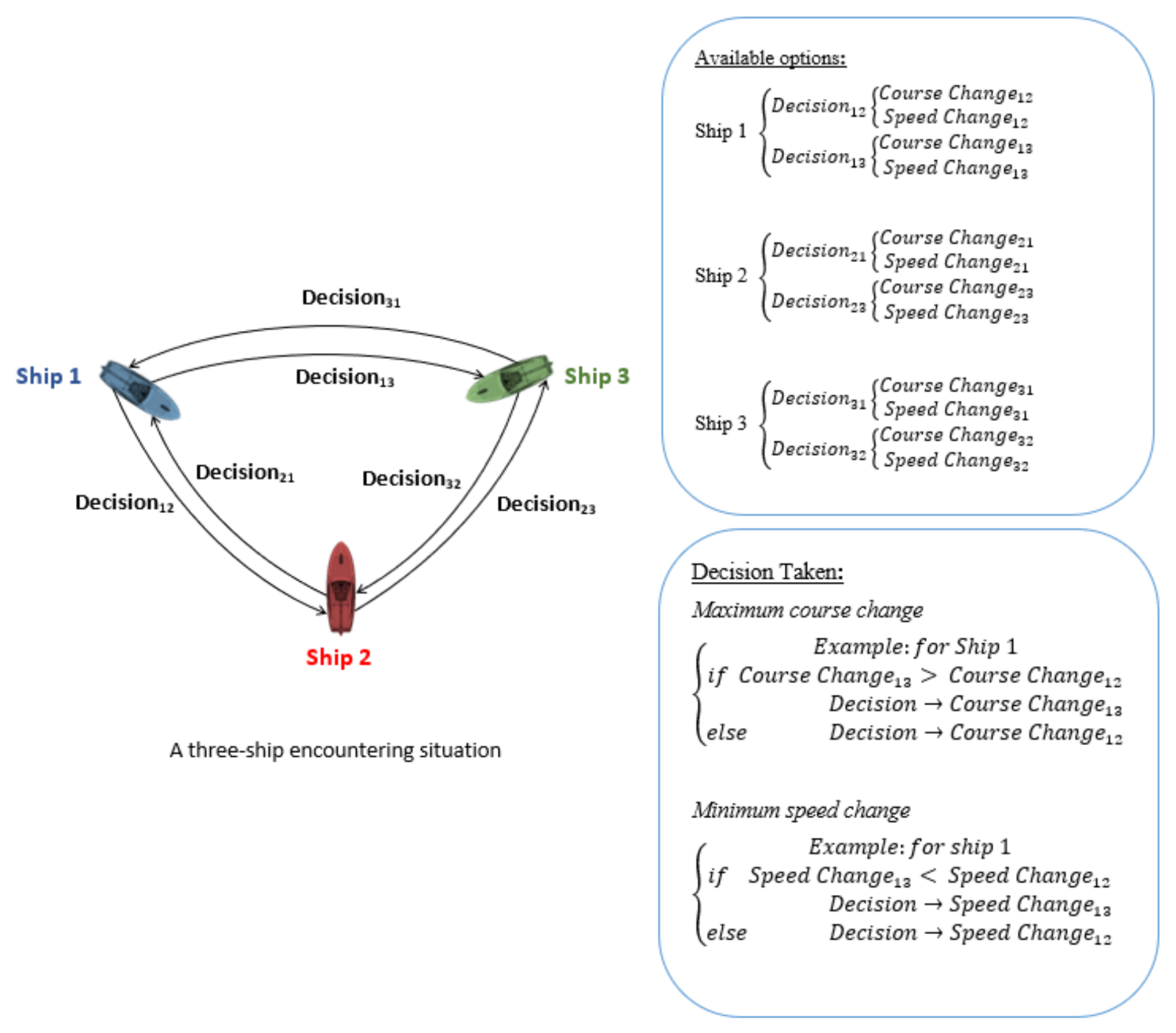
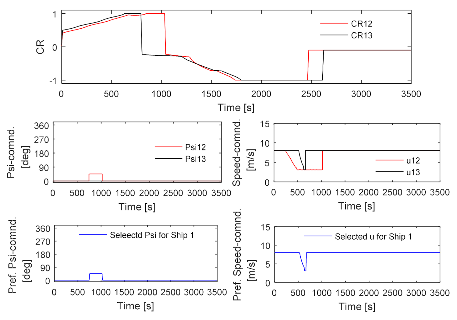
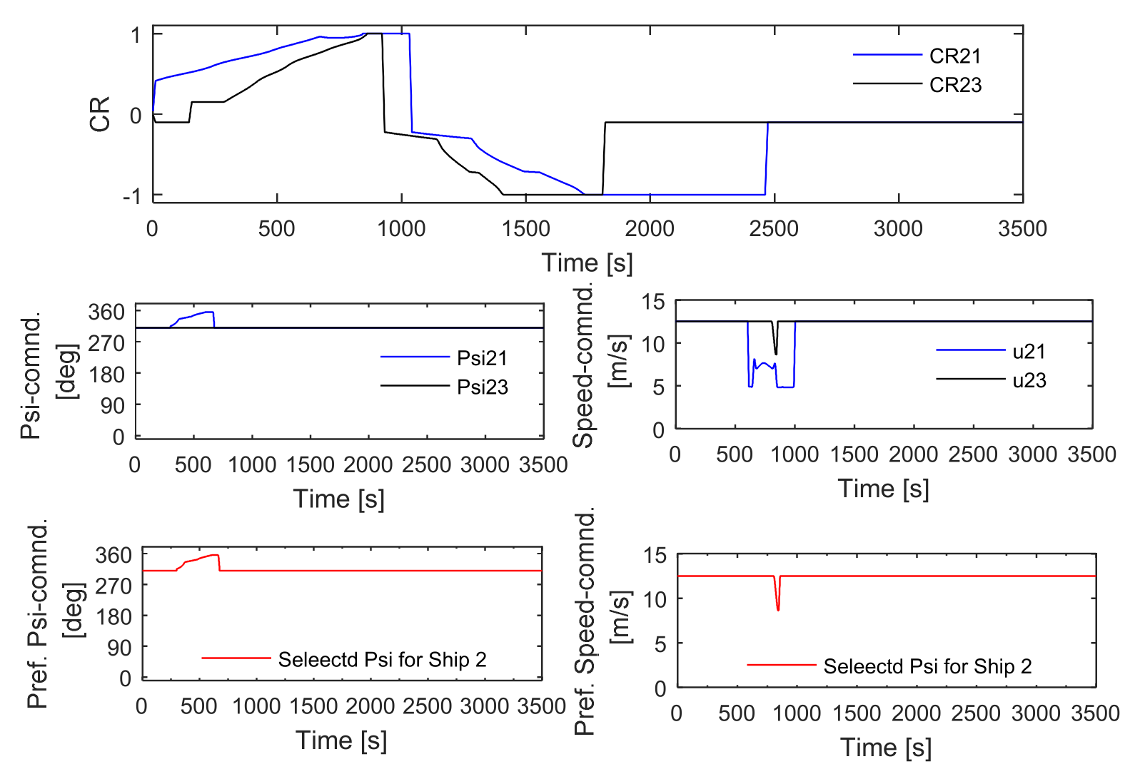
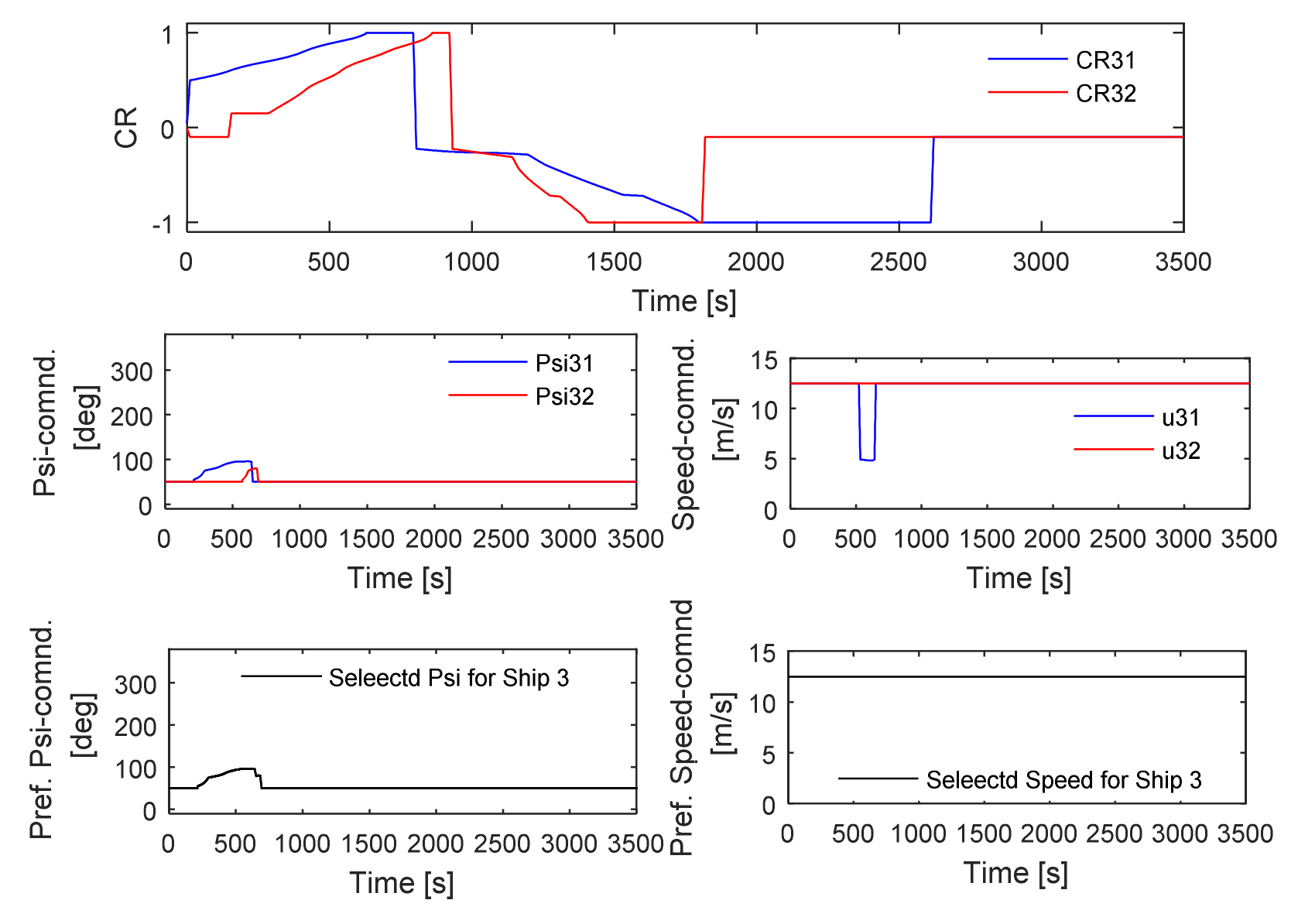
The conflict resolution module is also designed to calculate the evasion actions necessary to avoid each ship. This means that each ship will have two options to choose from to avoid the other two ships in three ship encounters. Similarly, for four and five ship encounters, each ship will have three and four options, respectively. To opt for the most suitable option to avoid all the ships in an encounter, this research proposes to use a simple but effective maximum-course and minimum-speed change approach. In this approach, the system compares all available options calculated by the resolution module instantly and chooses the maximum-course and minimum-speed change command for execution. This adopted approach is then tested for complicated multiple-ship-encountering scenarios.

Simulation for Multiple Ship Encounters

At first, the proposed maximum-course and minimum-speed change strategies are tested for three ships, where ship 1 is encountering ship 2 and ship 3 from its port and starboard side, respectively, presenting two crossing situations. The initial positions, headings and speeds of the ships are selected for a collision course that would take place at (0, 0) if no actions are taken. Table 6 lists up the details of the three ships considered in the tested encounter.
The simulation result is shown in Figure 24, which demonstrates that the three ships avoid each other successfully. Each ship is marked at 500 s time interval to understand the time frame of ships’ avoidance action.
To understand the decision-making process for this multiple ship encounter, Figure 25, Figure 26 and Figure 27 are illustrated. Figure 25 describes the CR calculated for ship 2 and ship 3 measured from ship 1, which are noted as CR12 and CR13. For ship 1, two options are available for course changing, named Psi12 and Psi13 to avoid ship 2 and ship 3, respectively. The same goes for speed change, where the options are u12 and u13. According to the strategy, the course changing options are compared at each time, and the maximum value is selected. For example, because Psi 13 is zero, Psi 12 is chosen for ship 1. On the other hand, u12 and u13 are compared for minimum speed change, and thus u13 is preferred.
Figure 26 describes the details for ship 2 while taking evasive action. Here the options are highlighted by denoting the parameters as 21 and 23, which means the actions to be taken by ship 2 to avoid ship 1 and ship 3, respectively. Here, ship 2 chooses Psi21 and u12 as its avoiding action. For ship 3, the system chooses Psi31 and u31 as its avoiding action, the details of which can be found in Figure 27.
To increase the complexity, four and five-ship encounters are also tested. Table 7 shows the details of the extra two ships added into the three-ship encounters to judge the system’s effectiveness for four and five ship encounters.
Figure 28 and Figure 29 demonstrate the simulation results of these two cases, respectively. For ease of comparison, the initial states and the ships are considered as the same. The trajectories of the ships are demonstrated at 500s timestamp as well. Despite the fact that in both figures the ships avoid each other successfully, the actions taken by the ships to avoid each other must be analysed properly. For ship 1, the course changing pattern is much the same in both figures. However, Ship 2 initiates its starboard turn at an earlier stage to avoid Ship 5, as shown in Figure 29. Regarding ship 3, a slight variation in course changing command does exist, but it does not affect its course changing pattern much. For ship 4, the actions for course changing command are identical, whereas it runs at a reduced speed for quite a long time in five ship encountering situations. On the other hand, ship 5 takes a large starboard turn to avoid all ships in its course.
A number of similar cases are analysed in this study and found the ships are avoiding each other successfully. In order to consider a higher level of complexity, this study also attempts to solve Imazu-proposed 22 encountering cases, and the results are included in the following subsection.

6.4. The Proposed System to Solve Imazu Problems

Imazu problem [
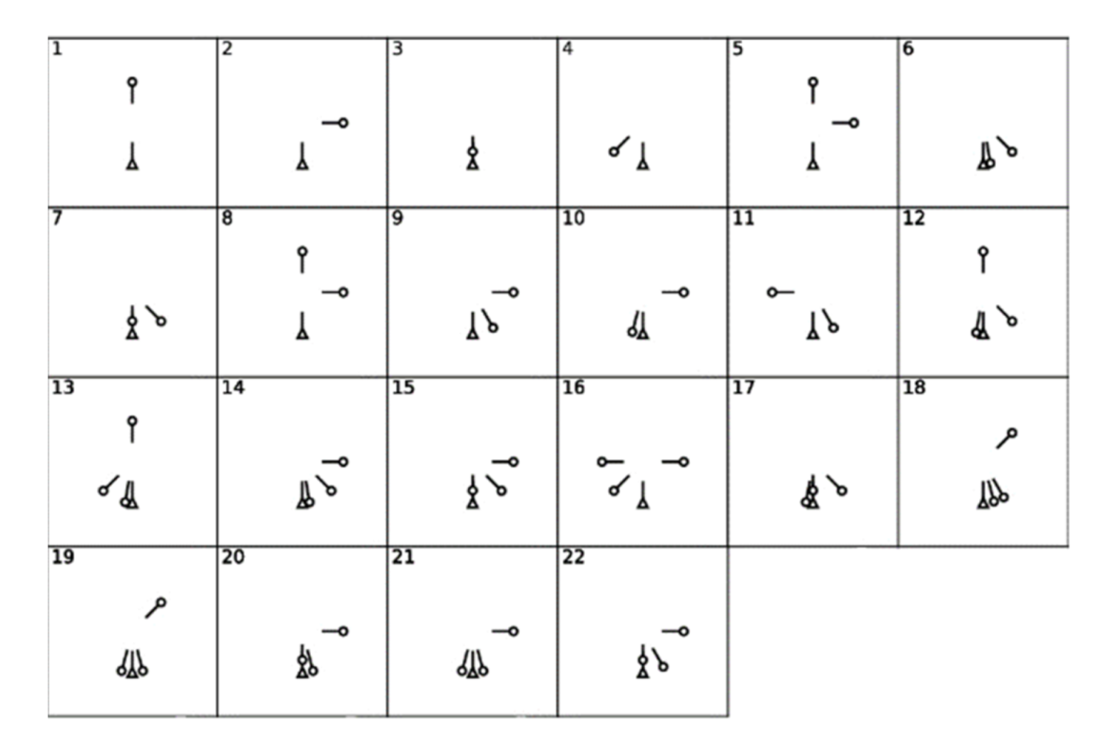
25] is chosen as a benchmark in this study. This problem consists of basic ship encounters of one on one and other difficult situations of multiple ship encounters. Figure 30 shows the 22 problems defined by Imazu, where numbers on the top left corner in each box indicate the case number. The short bar from the triangle and circle indicates the velocity vector of the ships. These 22 cases are tested with the proposed system and the maximum-course and minimum-speed change approach. The results are shown in
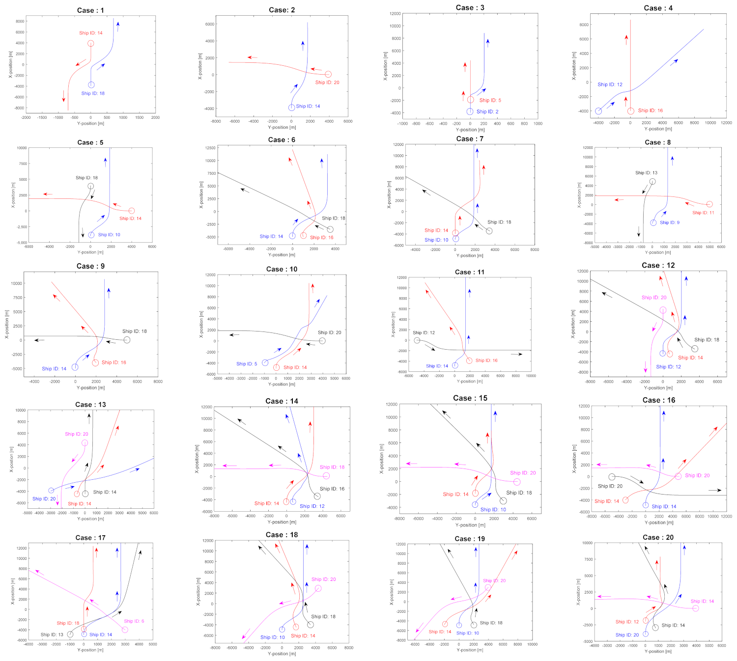
 Figure 31.
The ship types are randomly selected from Table 1 and mentioned in the form of Ship IDs in Figure 31. The initial positions, speed, and headings are selected based on the encountering situations mentioned in Figure 30. Additionally, all the ships are set in courses that are going to collide at the (0, 0) point in the simulation domain if no actions are taken. The results of all simulations show a successful demonstration of this proposed system as the ships avoid each other. The evasive actions taken by the ships are COLREGs compliant and also take the ship dynamics into account. 
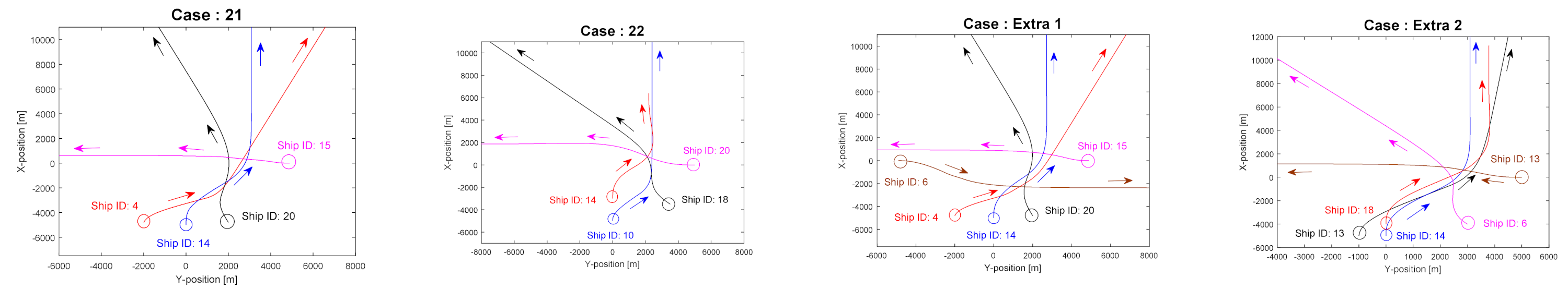
Figure 31 also demonstrates two extra cases with five ship encounters. Case extra 1 is considered by adding an extra ship (ship ID: 6) with a heading of 90 ° to the pre-existing case 21. This does not cause any drastic changes in the course changing pattern of other ships as the added ship takes adequate starboard rudder to avoid other ships. On the other hand, case extra 2 is considered by adding an extra ship (Ship ID: 13) with a heading of 270 ° to the pre-existing case 17. This added ship causes a drastic change in the course changing pattern of the other two ships, named Ship ID: 13 (red line) and Ship ID: 6 (pink line).
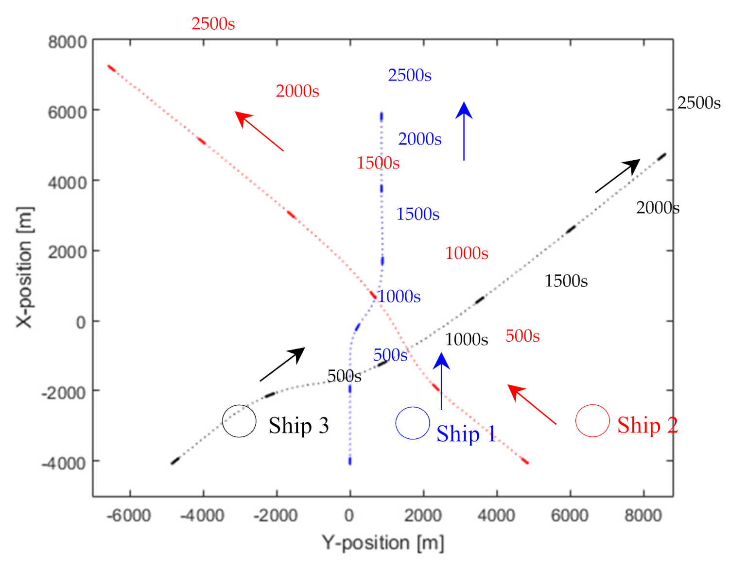
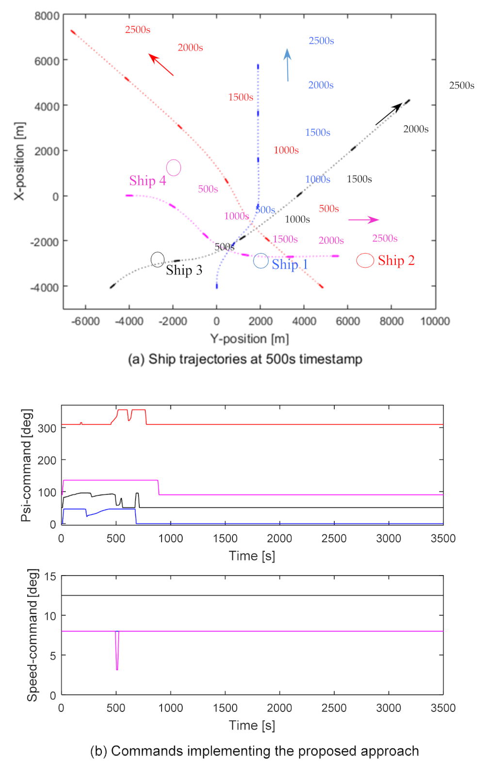
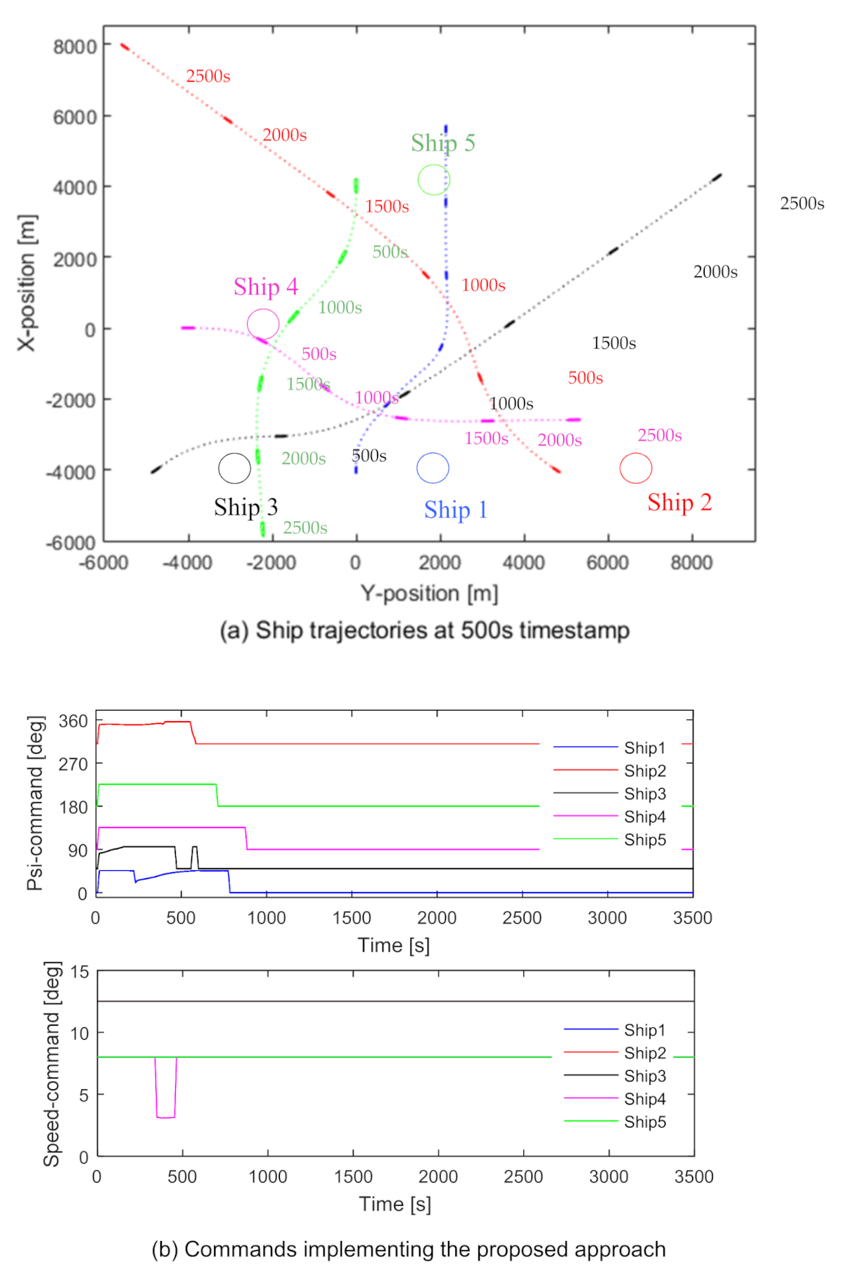
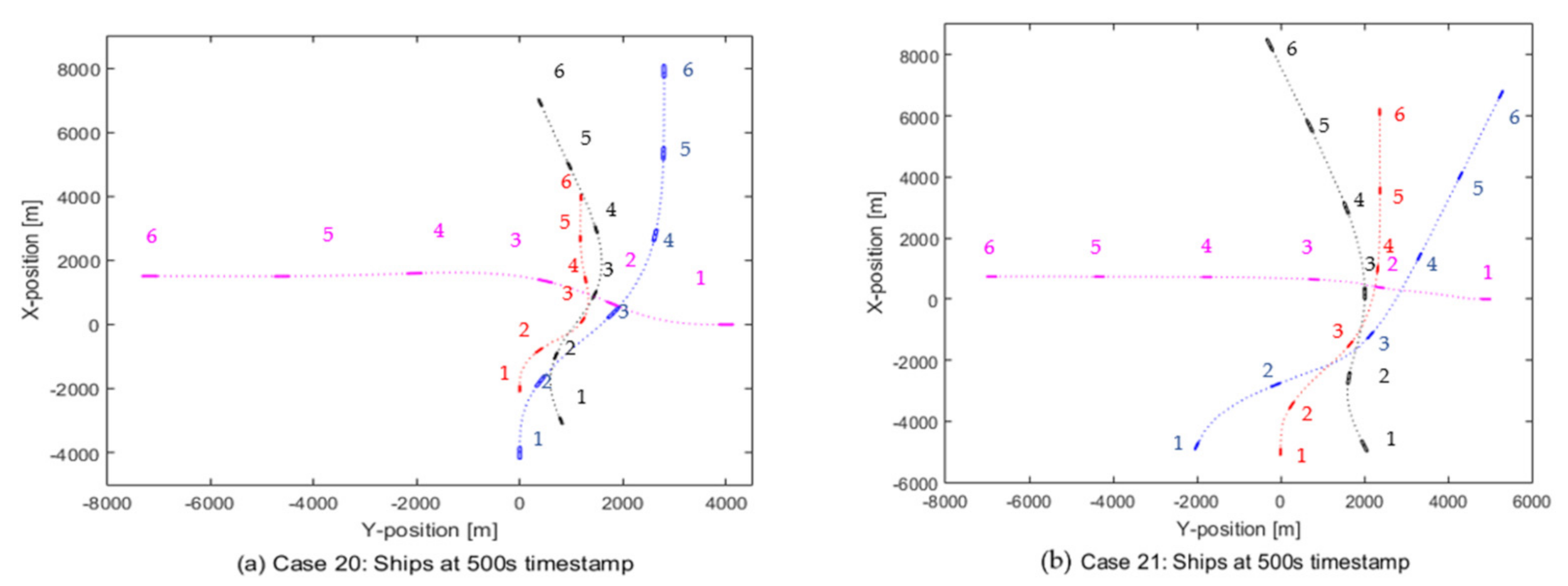
To demonstrate the timestamp of the ships’ evasive actions, two samples from Figure 31, case 20 and case 21, are chosen and shown in Figure 32. The integers in Figure 32 define the ship positions at 500 s interval, giving a clear understanding of how the system manages to guide all the ships to pass each other by maintaining a proper safety distance.
Finally, all these results show that the system is tolerant enough to consider more ships in any encountering situation proposed by Imazu. This study has analysed up to five ships in an encounter, which could be increased in future studies.

7. Conclusions and Future Studies

This study proposes a Fuzzy logic based novel collision avoidance system which not only takes care of the COLREGs rules while taking the evasive actions but also considers the ship dynamic. In this regard, the key input parameters are carefully selected, and the corresponding fuzzy membership functions are appropriately designed. COLREGs and the expert knowledge are unitized while defining the fuzzy rules to make the system COLREGs complaint. Later, the effectiveness of the proposed system is demonstrated for a simple one-to-one to complicated multiple ships encounters. Furthermore, a unique but straightforward effective maximum-course and minimum-speed change approach is also introduced for this system while dealing with the decision-making processes for multiple-ship encounters.
To summarize:
  • This research utilizes Nomoto’s equation in the motion prediction module to consider the ship dynamic and to predict the ship motion more realistically. Twenty different ships’ manoeuvring indices, i.e., K and T, are considered to distinguish the ship motion from each other.
  • Closest point of approach (CPA) is considered in the conflict detection module, but, unlike others, the DCPA and TCPA are non-dimensionalised by using the largest ship size and relative velocities in an encounter. This allows the system to consider ship size and speed effect and tune the risk value accordingly. Fuzzy membership functions are then designed for these two inputs, and Fuzzy rules are selected. To manipulate the risk for a higher number of ship encounters, scale factors (SF) are used to normalise the membership functions. These SFs are selected manually to ensure a safe crossing distance for up to five ship encounters at this stage of research.
  • The calculated risk (CR) from the conflict detection module and the encountering and relative angle of each ship measured from others are then used to construct a Fuzzy based conflict resolution module. Based on the types of encounters, the relative position measured from each ship is divided into seven parts. Then, for a different combination of encountering and relative angle, the COLREGs compliant rules are defined.
  • The conventional PD controller and speed response equation are chosen as a course and/or speed change module.
  • After carefully designing the modules, their integrity is tested for different ship encountering situations and found successful. The system is also verified for different ship types, sizes, and speeds.
  • A simple but effective maximum-course and minimum-speed change approach is introduced for multiple ship encounters while selecting the evasive action from multiple available options by the system.
  • Imazu problem is set as the benchmark in this study, and the proposed system has been found to give an effective and realistic solution for each of 22 cases maintaining the COLREGs rules.
  • The system is also tested for different complex encountering scenarios with up to five-ship encounters and found successful.
Despite the proposed system works effectively to avoid ship collisions in any complicated multiple ship encountering situation, further improvements can still be carried out, for example:
  • In the current study, the system assumes that all ships are aware of each other’s state and will take necessary steps to avoid each other. However, a ship might not be aware of other ship’s actions in a real situation, or it just avoids taking any action believing that other ships should take the lead. Those cases need to be investigated to check whether the system can guide others ships to avoid a non-commanding ship.
  • The system needs to be investigated for sensor noise tolerance before doing the test run in the near future.
  • Environmental disturbances such as current and wind effects have not been considered yet in the system. It would be interesting to see whether the proposed system could successfully guide the ships to avoid each other under such conditions.
  • The scale factors for the D C P A and T C P A are chosen manually at this stage, which can be automated and optimized for better results.
  • This study considers up to five-ship encounters. A greater number of ships could be considered in the near future to increase the complexity of the system.

Author Contributions

Conceptualization, Y.A.A., A.M. and M.A.H.; methodology, Y.A.A.; software, Y.A.A.; validation, Y.A.A.; formal analysis, Y.A.A. and M.Y.O.; investigation, Y.A.A., M.A.H.; resources, M.Y.O. and A.M.; data curation, M.Y.O.; writing—original draft preparation, Y.A.A.; writing—review and editing, M.A.H. and Y.A.A.; visualization, Y.A.A. and M.A.H.; supervision, Y.A.A.; project administration, M.A.H. and Y.A.A.; funding acquisition, Y.A.A. All authors have read and agreed to the published version of the manuscript.

Funding

A special thanks to Universiti Teknologi Malaysia (UTM) for the opportunity to carry out the research and the Ministry of Education (MOE) for financial support. This project was supported by Research University Grant-UTM ER [Vot Number: Q.J130000.3851.19J33] initiated by UTM.

Institutional Review Board Statement

Not Applicable.

Informed Consent Statement

Not Applicable.

Conflicts of Interest

The authors declare no conflict of interest. The funders had no role in the design of the study, in the collection, analyses, or interpretation of data, in the writing of the manuscript, or in the decision to publish the results.

References

  1. IMCA. Guidelines for The Design and Operation of Dynamically Positioned Vessels; Rev. 4.; IMCA M103; IMCA: London, UK, 2019. [Google Scholar]
  2. Chauvin, C.; Lardjane, S.; Morel, G.; Clostermann, J.P.; Langard, B. Human and organisational factors in maritime accidents: Analysis of collisions at sea using the HFACS. Accid. Anal. Prev. 2013, 59, 26–37. [Google Scholar] [CrossRef]
  3. Tam, C.; Bucknall, R.; Greig, A. Review of collision avoidance and path planning methods for ships in close range encounters. J. Navig. 2009, 62, 455–476. [Google Scholar] [CrossRef]
  4. IMO. Convention on the International Regulations for Preventing Collisions at Sea (COLREGs). 1972. Available online: http://www.imo.org/conventions/ (accessed on 20 July 2021).
  5. Fossen, T.I. Models for ships, offshore structures and underwater vehicles. In Handbook of Marine Craft Hydrodynamics and Motion Control; John Wiley Sons Ltd: Chichester, UK, 2011. [Google Scholar]
  6. Abdelaal, M.; Franzle, M.; Hahn, A. Nonlinear Model Predictive Control for trajectory tracking and collision avoidance of underactuated vessels with disturbances. Ocean Eng. 2018, 160, 168–180. [Google Scholar] [CrossRef]
  7. Eriksen, B.H.; Breivik, M.; Pettersen, K.Y.; Wiig, M.S. A modified dynamic window algorithm for horizontal collision avoidance for AUVs. In Proceedings of the 2016 IEEE Conference on Control Applications (CCA), Buenos Aires, Argentina, 19–22 September 2016; pp. 19–22. [Google Scholar]
  8. Li, S.J.; Liu, J.L.; Negenborn, R.R. Distributed coordination for collision avoidance of multiple ships considering ship maneuverability. Ocean Eng. 2019, 181, 212–226. [Google Scholar] [CrossRef]
  9. Mishra, P.; Panigrah, S.K.; Das, S. Ships Steering Autopilot Design by Nomoto Model. Int. J. Mech. Eng. Robot. 2015, 3, 37–41. [Google Scholar]
  10. Lee, H.J.; Rhee, K.P. Development of collision avoidance system by using expert system and search algorithm. Int. Shipbuild. Prog. 2001, 48, 197–212. [Google Scholar]
  11. Chin, H.C.; Debnath, A.K. Modeling perceived collision risk in port water navigation. Saf. Sci. 2009, 47, 1410–1416. [Google Scholar] [CrossRef] [Green Version]
  12. Yingjun, H.; Anmin, Z.; Wuliu, T.; Jinfen, Z.; Zebei, H. Multi-Ship Collision Avoidance Decision-Making Based on Collision Risk Index. J. Mar. Sci. Eng. 2020, 8, 640. [Google Scholar] [CrossRef]
  13. Simsir, U.; Amasyalı, M.F.; Bal, M.; Çelebi, U.B.; Ertugrul, S. Decision support system for collision avoidance of vessels. Appl. Soft Comput. 2014, 25, 369–378. [Google Scholar] [CrossRef]
  14. Li, L.; Wu, D.; Huang, Y.; Yuan, Z.M. A path planning strategy unified with a COLREGS collision avoidance function based on deep reinforcement learning and artificial potential field. Appl. Ocean Res. 2021, 113, 102759. [Google Scholar] [CrossRef]
  15. Szlapczynski, R.; Szlapczynska, J. Review of ship safety domains: Models and applications. Ocean Eng. 2017, 145, 277–289. [Google Scholar] [CrossRef]
  16. Naeem, W.; Irwin, G.W.; Yang, A.L. COLREGs-based collision avoidance strategies for unmanned surface vehicles. Mechatronics 2012, 22, 669–678. [Google Scholar] [CrossRef]
  17. Tam, C.; Bucknall, R. Cooperative path planning algorithm for marine surface vessels. Ocean Eng. 2013, 57, 25–33. [Google Scholar] [CrossRef]
  18. Fang, M.-C.; Tsai, K.-Y.; Fang, C.-C. A simplified simulation model of ship navigation for safety and collision avoidance in heavy traffic areas. J. Navig. 2017, 71, 837–860. [Google Scholar] [CrossRef]
  19. Praczyk, T. Neural Anti-collision system for Autonomous Surface Vehicle. Neurocomputing 2015, 149, 559–572. [Google Scholar] [CrossRef]
  20. Perera, L.P.; Carvalho, J.P.; Soares, C.G. Intelligent ocean navigation and fuzzy bayesian decision/action formulation. IEEE J. Ocean. Eng. 2012, 37, 204–219. [Google Scholar] [CrossRef]
  21. Ge, S.S.; Cui, Y.J. Dynamic motion planning for mobile robots using potential field method. Auton. Robot. 2002, 13, 207–222. [Google Scholar] [CrossRef]
  22. Lyu, H.; Yin, Y. COLREGS-constrained real-time path planning for autonomous ships using modified artificial potential fields. J. Navig. 2018, 72, 588–608. [Google Scholar] [CrossRef]
  23. Benjamin, M.R.; Leonard, J.J.; Curcio, J.A.; Newman, P.M. A method for protocol-based collision avoidance between autonomous marine surface craft. J. Field Rob. 2006, 23, 333–346. [Google Scholar] [CrossRef] [Green Version]
  24. Szlapczynski, R. A unified measure of collision risk derived from the concept of a ship domain. J. Navig. 2006, 59, 477–490. [Google Scholar] [CrossRef]
  25. Imazu, H. Research on Collision Avoidance Manoeuvre. Ph.D. Thesis, The University of Tokyo, Tokyo, Japan, 1987. (In Japanese). [Google Scholar]
  26. Zaccone, R. COLREG-Compliant Optimal Path Planning for Real-Time Guidance and Control of Autonomous Ships. J. Mar. Sci. Eng. 2021, 9, 405. [Google Scholar] [CrossRef]
  27. Zaccone, R.; Martelli, M.; Figari, M. A COLREG-Compliant Ship Collision Avoidance Algorithm. In Proceedings of the IEEE European Control Conference-ECC2019, Naples, Italy, 25–28 June 2019; pp. 2530–2535. [Google Scholar]
  28. Smierzchalski, R.; Michalewicz, Z. Modeling of ship trajectory in collision situations by an evolutionary algorithm. IEEE Trans Evol. Comput. 2000, 4, 227–241. [Google Scholar] [CrossRef] [Green Version]
  29. Li, X.R.; Jilkov, V.P. Survey of maneuvering target tracking. Part I. Dynamic models. IEEE Trans. Aerosp. Electron. Syst. 2003, 39, 1333–1364. [Google Scholar] [CrossRef]
  30. Liu, C.; Negenborn, R.R.; Chu, X.; Zheng, H. Predictive path following based on adaptive line-of-sight for underactuated autonomous surface vessels. J. Mar. Sci. Technol. 2017, 23, 483–494. [Google Scholar] [CrossRef]
  31. Aisjah, A.S. An Analysis Nomoto Gain and Norbin Parameter on Ship Turning Maneuver. IPTEK J. Technol. Sci. 2010, 21. [Google Scholar] [CrossRef] [Green Version]
  32. Golikov, V.A.; Golikov, V.A.; Volyanskaya, Y.; Mazur, O.; Onishchenko, O. A simple technique for identifying vessel model parameters. IOP Conf. Ser. Earth Environ. Sci. 2018, 172, 012010. [Google Scholar] [CrossRef]
  33. Radanovic, M.; Piera Eroles, M.A.; Koca, T.; Ramos Gonzalez, J.J. Surrounding traffic complexity analysis for efficient and stable conflict resolution. Transport. Res. Part C Emerg. Technol. 2018, 95, 105–124. [Google Scholar] [CrossRef]
  34. Wu, B.; Yip, T.L.; Xie, L.; Wang, Y. A fuzzy-MADM based approach for site selection of offshore wind farm in busy waterways in China. Ocean Eng. 2018, 168, 121–132. [Google Scholar] [CrossRef]
  35. Wu, B.; Yip, T.L.; Yan, X.; Guedes Soares, C. Fuzzy logic based approach for ship bridge collision alert system. Ocean Eng. 2019, 187, 106152. [Google Scholar] [CrossRef]
  36. Woerner, K.; Benjamin, M.R.; Novitzky, M.; Leonard, J.J. Quantifying protocol evaluation for autonomous collision avoidance. Auton. Robot. 2018, 43, 967–991. [Google Scholar] [CrossRef] [Green Version]
  37. He, Y.X.; Jin, Y.; Huang, L.W.; Xiong, Y.; Chen, P.F.; Mou, J.M. Quantitative analysis of COLREG rules and seamanship for autonomous collision avoidance at open sea. Ocean Eng. 2017, 140, 281–291. [Google Scholar] [CrossRef]
  38. Perera, L.P.; Carvalho, J.P.; Guedes Soares, C. Fuzzy logic based decision making system for collision avoidance of ocean navigation under critical collision conditions. J. Mar. Sci. Technol. 2011, 16, 84–99. [Google Scholar] [CrossRef]
Figure 1. Information flow among the modules for the proposed collision avoidance system.
Jmse 09 00790 g001
Figure 2. Different encountering situations: Own Ship—(a) overtaking, (b) head-on; Own Ship ‘Give way’—(c) parallel-crossing, (df) crossing other orientations; Own Ship ‘Stand on’—(g) parallel-crossing, (hj) crossing other orientations.
Jmse 09 00790 g002
Figure 3. Coordinate system used in perdition model.
Jmse 09 00790 g003
Figure 4. Defining DCPA and TCPA for a two-ship encounter.
Jmse 09 00790 g004
Figure 5. Fuzzy inference system for CR calculation.
Jmse 09 00790 g005
Figure 6. Normalised membership functions for D C P A and T C P A .
Jmse 09 00790 g006
Figure 7. Membership function for CR.
Jmse 09 00790 g007
Figure 8. Illustration of fuzzy rules for CR calculation: (a) 3D plot, (b) 2-D contour plot.
Jmse 09 00790 g008
Figure 9. Defining encountering and relative angle.
Jmse 09 00790 g009
Figure 10. Categorized encountering situations.
Jmse 09 00790 g010
Figure 11. Mapping of encountering situations for different relative and encountering angles.
Jmse 09 00790 g011
Figure 12. Membership functions for relative angle, encountering angle, and collision risk.
Jmse 09 00790 g012
Figure 13. Membership functions for heading and speed change.
Jmse 09 00790 g013
Figure 14. Decision making strategy for multiple ship encounters.
Jmse 09 00790 g014
Figure 15. PD controller for course changing.
Jmse 09 00790 g015
Figure 16. Two ships in a collision route.
Jmse 09 00790 g016
Figure 17. Collison avoidance using the proposed algorithm for the case in Figure 16.
Jmse 09 00790 g017
Figure 18. Outcomes of the three modules for a given two-ship encountering situation.
Jmse 09 00790 g018
Figure 19. Case 1: Two small ships in an encounter.
Jmse 09 00790 g019
Figure 20. Case 2: One small and one medium ships in an encounter.
Jmse 09 00790 g020
Figure 21. Case 3: Two large ships in an encounter.
Jmse 09 00790 g021
Figure 22. Case 1: Parallel crossing with slow speed.
Jmse 09 00790 g022
Figure 23. Case 2: Parallel crossing with relatively higher speed.
Jmse 09 00790 g023
Figure 24. Collision avoidance with a three-ship encounter.
Jmse 09 00790 g024
Figure 25. Maximum-course and minimum-speed change selection for Ship 1.
Jmse 09 00790 g025
Figure 26. Maximum-course and minimum-speed change selection for Ship 2.
Jmse 09 00790 g026
Figure 27. Maximum-course and minimum-speed change selection for Ship 3.
Jmse 09 00790 g027
Figure 28. Four-ship encounter with maximum-course and minimum-speed change approach: (a) Trajectories of all ships. (b) Implementation of proposed approach.
Jmse 09 00790 g028
Figure 29. Five-ship encounter with maximum-course and minimum-speed change approach: (a) Trajectories of all ships. (b) Implementation of proposed approach.
Jmse 09 00790 g029
Figure 30. Imazu problem.
Jmse 09 00790 g030
Figure 31. Collision avoidance algorithm to solve Imazu problem.
Jmse 09 00790 g031aJmse 09 00790 g031b
Figure 32. Two sample cases from Imazu problem (ships at 500 timestamps interval): (a) Case 20, (b) Case 21.
Jmse 09 00790 g032
Table 1. The Constant Time System Approaches and Gain Control for Selected Ship Types.
IDType of ShipL (m)U (m/s)T (s) K T ´ K ´
1Harbour Tug43.265.1542.210.193925.031.63
2US River Tow Boat43.35.1564.230.193927.641.63
3Offshore Supply58.286.6963.110.094257.240.82
4Tuna Seiner72.038.2339.940.2044.561.79
5Container High speed78.1814.6733.360.1486.260.79
6Car Ferry93.5610.2946.60.2195.131.99
7Cargo Liners141.7810.8190.820.0846.921.10
8Lumber Low Speed152.047.72155.730.04297.910.84
9General Cargo Low Speed152.097.72127.220.1366.462.68
10Mariner161.97.72107.890.1845.143.86
11RO/RO193.5911.32116.510.2856.814.87
12Container Med. Speed209.411.32132.610.0657.171.20
13OBO (Panamax)237.657.72277.450.0659.012.00
14Tanker (Panamax)239.748.24295.140.02110.140.61
15Barge Carrier244.039.78178.10.1687.144.19
16LNG (125,000 m3)270.1110.29217.870.07998.302.10
17OBO (150,000 dwt)270.397.72301.190.07998.602.80
18Tanker 100,000–350,000 dwt304.658.24289.820.02397.840.88
19OBO (300,000 dwt)310.47.72345.070.01798.580.72
20Tanker 350,000 dwt409.598.24418.60.01848.420.91
Table 2. Fuzzy rules for CR calculation.
CR TCPA
SANMENDANDAPDMPMEPSMPSAP
DCPADASANMENDANDAPDMPMEPSMPSAP
DMSANSANMENDMPMEPSMPSAPSAP
MESANSANSANMEPSMPSAPSAPSAP
SMSANSANSANSMPSAPSAPSAPSAP
SASANSANSANSAPSAPSAPSAPSAP
Table 3. Fuzzy rules for heading and/or speed change.
Relative AngleEncountering AngleCollision Risk
LMHVHVHHLMHVHVHH
Heading ChangeSpeed Change
IaZeroPSPMPLPLZeroZeroZeroZeroNL
bZeroPSPMPLPLZeroZeroZeroZeroNL
cZeroPSPMPLPLZeroZeroZeroZeroNL
dZeroPSPMPLPLZeroZeroZeroZeroNL
eZeroPSPMPLPLZeroZeroZeroZeroNL
fZeroPSPMPLPLZeroZeroZeroZeroZero
gZeroZeroZeroZeroPLZeroZeroZeroZeroZero
hZeroZeroZeroZeroPLZeroZeroZeroZeroZero
iZeroZeroZeroZeroPLZeroZeroZeroZeroZero
jZeroPSPMPLPLZeroZeroZeroZeroNL
IIbZeroPSPMPLPLZeroZeroZeroZeroNL
cZeroPSPMPLPLZeroZeroZeroZeroNL
dZeroPSPMPLPLZeroZeroZeroZeroNL
eZeroPSPMPLPLZeroZeroZeroZeroNL
IIIaZeroZeroZeroZeroZeroZeroNSNLNLNL
bZeroZeroZeroZeroZeroZeroNSNLNLNL
cZeroZeroZeroZeroZeroZeroNSNL NLNL
dZeroZeroZeroZeroZeroZeroNSNL NLNL
eZeroZeroZeroZeroZeroZeroNSNL NLNL
IVa~jZeroZeroZeroZeroZeroZeroZeroZeroZeroZero
VfZeroZeroZeroZeroZeroZeroZeroZeroZeroNL
gZeroZeroZeroZeroZeroZeroZeroZeroZeroNL
hZeroZeroZeroZeroZeroZeroZeroZeroZeroNL
iZeroZeroZeroZeroZeroZeroZeroZeroZeroNL
jZeroZeroZeroZeroZeroZeroZeroZeroZeroNL
VIfZeroPSPMPLPLZeroZeroZeroZeroNL
gZeroPSPMPLPLZeroZeroZeroZeroNL
hZeroPSPMPLPLZeroZeroZeroZeroNL
iZeroZeroZeroZeroPLZeroZeroZeroZeroZero
VIIaZeroPSPMPLPLZeroZeroZeroZeroNL
bZeroPSPMPLPLZeroZeroZeroZeroNL
cZeroPSPMPLPLZeroZeroZeroZeroNL
dZeroPSPMPLPLZeroZeroZeroZeroNL
eZeroPSPMPLPLZeroZeroZeroZeroNL
fZeroPSPMPLPLZeroZeroZeroZeroZero
gZeroZeroZeroZeroPLZeroZeroZeroZeroZero
hZeroZeroZeroZeroPLZeroZeroZeroZeroZero
iZeroZeroZeroZeroPLZeroZeroZeroZeroZero
jZeroPSPMPLPLZeroZeroZeroZeroNL
Table 4. Case Studies for Two-ship Encounters with Different Ship-Size-Combination.
CaseShip Type of ShipL (m)U (m/s)HeadingPosition
1Ship 1Offshore Supply58.2810 0 ° (−4000, 0)
Ship 2Tuna Seiner72.0310 210 ° (3500, 2000)
2Ship 1Container High speed78.1810 0 ° (−4000, 0)
Ship 2Tanker (Panamax)239.7410 210 ° (3500, 2000)
3Ship 1Tanker 100,000–350,000 dwt304.6510 0 ° (−4000, 0)
Ship 2Tanker 350,000 dwt409.5910 210 ° (3500, 2000)
Table 5. Case Studies for Two-ship Encounters with Different Ship Speed.
CaseShipType of ShipL (m)U (m/s)HeadingPosition
1Ship 1Container High speed78.186 0 ° (−4000, 0)
Ship 2RO/RO193.596 330 ° (−3464, 2000)
2Ship 1Container High speed78.1812 0 ° (−4000, 0)
Ship 2RO/RO193.5912 330 ° (−3464, 2000)
Table 6. Scenario for a Three-ship Encounter.
ShipType of ShipL (m)U (m/s)HeadingPosition
Ship 1Container Med. Speed209.48 0 ° (−4000, 0)
Ship 2Tanker (Panamax)239.7412.5 310 ° (−4000, 4767)
Ship 3LNG (125,000 m3)270.1112.5 50 ° (−4000, −4767)
Table 7. Added ship information for four and five ship encounters.
ShipType of ShipL (m)U (m/s)HeadingPosition
Ship 4Tanker 304.658 90 ° (0, −4000)
Ship 5Tanker 350,000 dwt409.598 180 ° (4000, 0)
Publisher’s Note: MDPI stays neutral with regard to jurisdictional claims in published maps and institutional affiliations.

