A Systematic Review of the Multi-Resolution Modeling (MRM) for Integration of Live, Virtual, and Constructive Systems


1
Department of Industrial Engineering and Management Systems, University of Central Florida, Orlando, FL 32816, USA
2
Faculty of Industrial Engineering and Management Systems, University of Central Florida, Orlando, FL 32816, USA
*
Author to whom correspondence should be addressed.
Information 2020, 11(10), 480; https://0-doi-org.brum.beds.ac.uk/10.3390/info11100480
Submission received: 17 August 2020
/
Revised: 27 September 2020
/
Accepted: 8 October 2020
/
Published: 14 October 2020
(This article belongs to the Special Issue Distributed Simulation 2020)
Abstract
:Multi-Resolution Modeling (MRM) is a modeling technology that creates a model that expresses the same phenomenon at more than two different resolutions. Since the advent of distributed simulation systems, the MRM study began in the military field, where the modeling and simulation (M&S) was most actively developed and was recognized as an essential area in the integrated system of live, virtual and constructive (LVC) simulations. Models of the various resolutions had already been built based on the characteristics and training purposes of each weapon system, and the interoperability of these models was a primary task in the M&S community. In this study, we report the results from a systematic review of the MRM to address two questions: (1) What research has been done towards the MRM for integrating LVC system? (2) What are the research and technology challenges for the MRM implementation in the future? In total, 22 papers have been identified and studied in this review by following the Preferred Reporting Items for Systematic Reviews and Meta-Analyses (PRISMA) guidelines. The structures of the significant 20 MRM implementation experiments in those papers are analyzed based on the relationship between the MRM and integrating the LVC system being implemented in the military. We explored the various issues related to the MRM. Then, we discussed the direction in which the MRM should move forward, comparing civilian modeling techniques with those being used in the military.
1. Introduction
At the end of the twentieth century, when modeling and simulation implementations were increasing, research on distributed simulation systems linking two or more simulations began in earnest. These studies were conducted in the military, which seeks to build a huge synthetic battlefield for practical and effective training. The most representative effort was the integration of LVC systems. They have also developed standard simulation architectures to link these simulations. However, since most of the simulation models used at that time were of fixed level resolution, problems were identified due to the different resolutions. The efforts to connect these models have evolved into Multi-Resolution Modeling (MRM). Resolution can be defined as “the degree of detail and precision used in the resolution of real-world aspects in a model or simulation” [1].
There are two main reasons why MRM is important in the military field. Firstly, models of different resolutions have already been developed by the needs of each military system. If there was a complete system that supported all these levels of resolution, not only would there be no problem associated with integration, but there would be no need to study MRM. Over the past few decades, however, numerous simulation models that are suitable for each weapon system have been developed, so utilizing them is economically better than creating a new platform the encompasses all systems [2]. Secondly, a successful LVC framework requires addressing issues associated with interoperability and composability. The interoperability handles the software and implementation details of interoperation, including data exchange. The composability, on the other hand, resolves the alignment of problems at the modeling level [2,3]. Although MRM is related to the composability in terms of addressing issues at the modeling level, it is also associated with the interoperability in terms of control of resolution.
In this article, we provide a systematic review of the MRM for the integration of LVC systems. Our goal is to provide information about the process by which the MRM has been developed and to reflect on the current modeling technique trends to identify future research directions. The purpose of this review is to analyze the results of the MRM implementations regarding the integration of LVC simulations and to identify issues that need to be further addressed. This study gives answers to two questions:
- What research has been done towards the MRM for integrating LVC systems?
- What are the research and technology challenges for the MRM implementation in the future?
This paper provides a systematic review of the MRM approaches with a new perspective. The relationship between the LVC system and MRM being implemented in the military is analyzed. This paper also discussed the direction in which the MRM should move forward.
2. Related Work
2.1. Multi-Resolution Modeling
Multi-Resolution Modeling (MRM) is defined as “building a single model, a family of models, or both to describe the same phenomena at different levels of resolution” [4]. MRM is the most challenging area of research in M&S and one of the critical technologies in the development of the distributed interactive simulation of complex systems [2,3,5,6].
The MRM first appeared in the 1990s with the emergence of the High-Level Architecture (HLA), when distributed simulation was developing [6,7]. In terms of replacing the actual system, high-resolution models that specifically describe the fundamental phenomenon are desirable, however, building high-resolution models with their insatiable demand for data is expensive, time-consuming, and often unavailable or unreliable [4]. On the other hand, the MRM is a hierarchical model that contains different levels of abstraction; it allows for a given level of abstraction to concentrate on the key information required by stakeholders, and to relegate irrelevant data to other levels of abstraction. In the study of the behavior of a watershed model with several abstraction levels and time granularity levels, the efficiency of a modeling scheme involving both abstraction hierarchies and time granularity has been verified, even though a lower abstraction model appears more competitive than others [8]. This means that it is efficient to express the model in various resolutions. Moreover, with the development of computer technology and the continued expansion of the simulation scale, simulation models with a fixed resolution can no longer achieve the simulated fidelity and complex needs of advanced military simulations [9]. The MRM enables designers to identify the conceptual and analytical model and entity breakdowns. The importance of MRM is based on the need for different levels of resolution in the model to understand the problem, while developing an advanced simulation infrastructure [10].
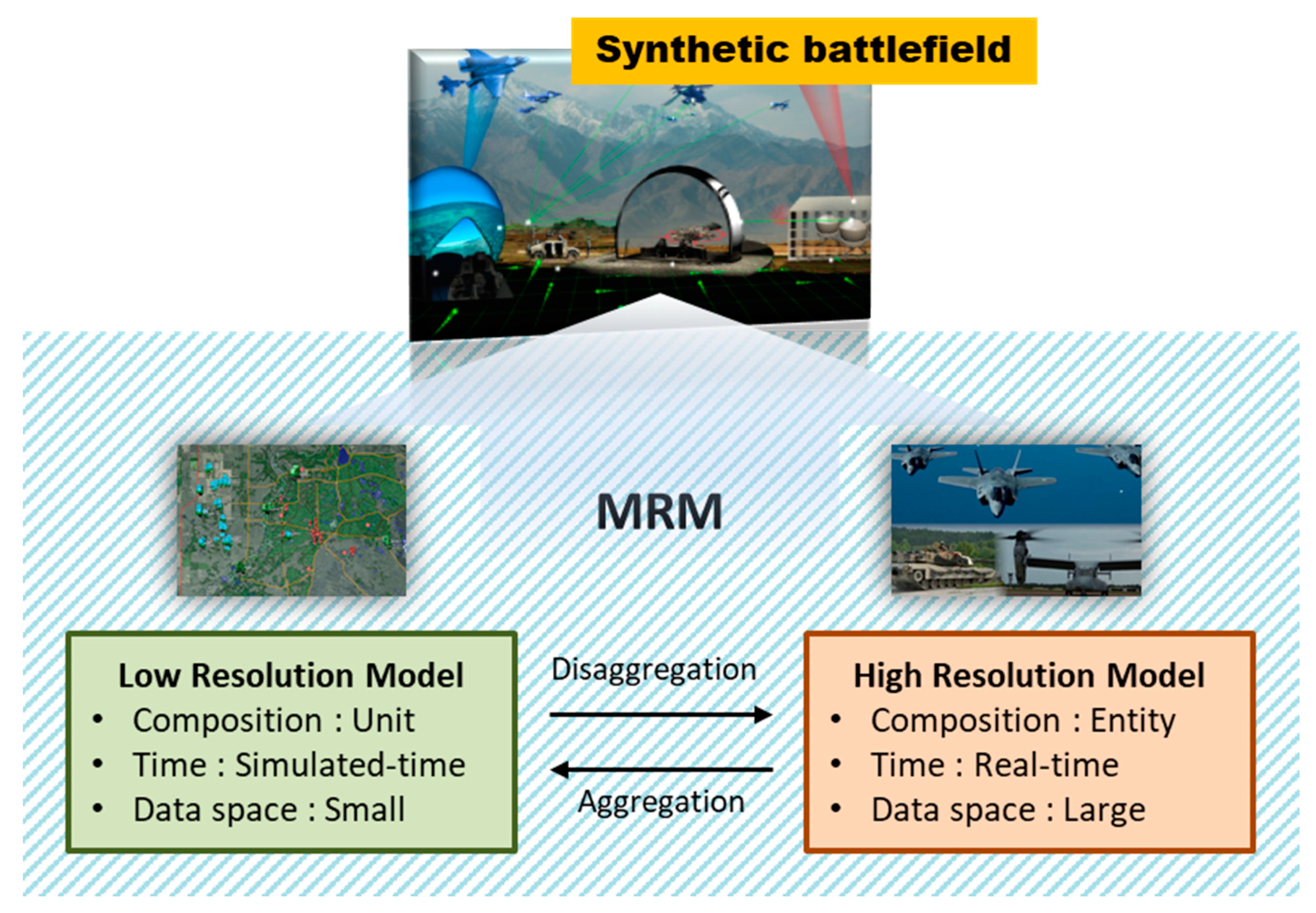
The MRM has been developing in various fields, which include the multi-resolution model on pedestrian evacuation under emergency situations [11], the distributed modeling and simulation framework for the improvement of sustainability in smart supply chains and manufacturing factories [12], the multi-resolution train operation model to improve the train control system simulation platform [13], and so on. This study, though, focuses on the military area that has developed this concept, as depicted in Figure 1. Composition and resolution changes related to the objects at different levels of resolution in MRM involve decomposing process. A low-resolution model (LRM) can be divided into multiple high-resolution models (HRM), and many HRMs can combine to form one LRM. The former is “disaggregation,” and the latter is “aggregation”. The aggregated object is called a “unit”, and the disaggregated objects are called “entities”.
2.2. Live, Virtual and Constructive (LVC) Systems
Military simulations are divided into live, virtual and constructive simulations according to three criteria—people, systems and the operation. A simulation in which real people operate the real system is called live simulation (e.g., a pilot flying a fighter). If real people use simulated systems in a simulated operation, it is called virtual simulation (e.g., a pilot flying a flight simulator). If no real person or system is involved in a simulated operation, it is a constructive simulation (e.g., computer-generated forces (CGF)) [17,18,19,20,21].
In the early days, LVC was the term used for each simulation, as explained above, but as the 21st century entered, its meaning began to change. The current LVC refers to the integration of live, virtual, and constructive simulations within a commonly simulated battlespace. This is because each model and simulation were designed and utilized for training and analysis purposes, meeting the needs of users. It was identified that a single model alone has limitations, such as the constraints of the training environment, high cost, gap from reality, and accuracy of analysis [22].
In the late 1980s, when the LVC taxonomy was formed, the situation in which simulated people use real systems was not considered. Since then, the US Department of Defense (DoD) has pointed out that there is a problem with the LVC classification system because it does not include a category for simulated people operating real systems. In Ref. [20], the same issue was mentioned, namely, that it has still not been officially named even though technology has progressed to the point where unmanned vehicles or systems are entirely operated. This system can be classified as ‘unmanned’, which is a terminology that the military is commonly using. However, the term LVC is used in this study. These concepts and terms are summarized in Table 1.
The LVC system provides a comprehensive and realistic simulation exercise environment, which also helps in reducing workload and network traffic by exploiting proper models of different levels of resolution together [23]. For example, the practical training of various entities within an artificially constructed synthetic battlefield involves live systems that perform actual maneuvers, virtual systems that simulate friendly forces or enemies, and constructive simulation that makes the battlefield seem plausible with realistic scenarios [24]. Therefore, MRM is one of the essential parts in operating the LVC system without any problems.
2.3. High-Level Architecture (HLA)
With the emergence of the concept of “co-simulation”, or “distributed simulation”, that interlocks two or more simulations, a few federation architectures, including simulation networking (SIMNET), distributed interactive simulation (DIS), high-level architecture (HLA) and test and training enabling architecture (TENA), have been developed. These architectures have been developed to link the simulations, and the HLA has been perceived as the best fit for implementing MRM.
The HLA has provided a common architecture supporting the reuse and interoperation of simulations since it was mandated as the standard for all M&S activities within the US DoD in 1996. The HLA was developed on the premise that one simulation cannot meet the needs of a variety of users and that it is impossible to predict how simulations will change in the future [20,25,26]. This means that even as new simulations are developed, they must be configured to be easily combined with legacy simulations. These assumptions made HLA itself a well-defined modular component of function and interface. Furthermore, HLA is based on the idea of decoupling simulation functions from the infrastructure required for communication between simulations. Overall, the HLA is defined by three components. The first is the HLA framework and rules, which ensure the proper interaction of federates in a federation. The second component is the HLA object model template (OMT). This describes the object model that defines the information generated or required by the simulation application and provides specifications for adjusting the definitions between simulations to create a standard data model for interoperability. The third component is the run-time infrastructure (RTI), which is the service specification that allows simulations to connect, exchange data, and coordinate activities during distributed runtime [26,27]. These three components formally define the HLA, but the HLA federation consists of three functional parts.
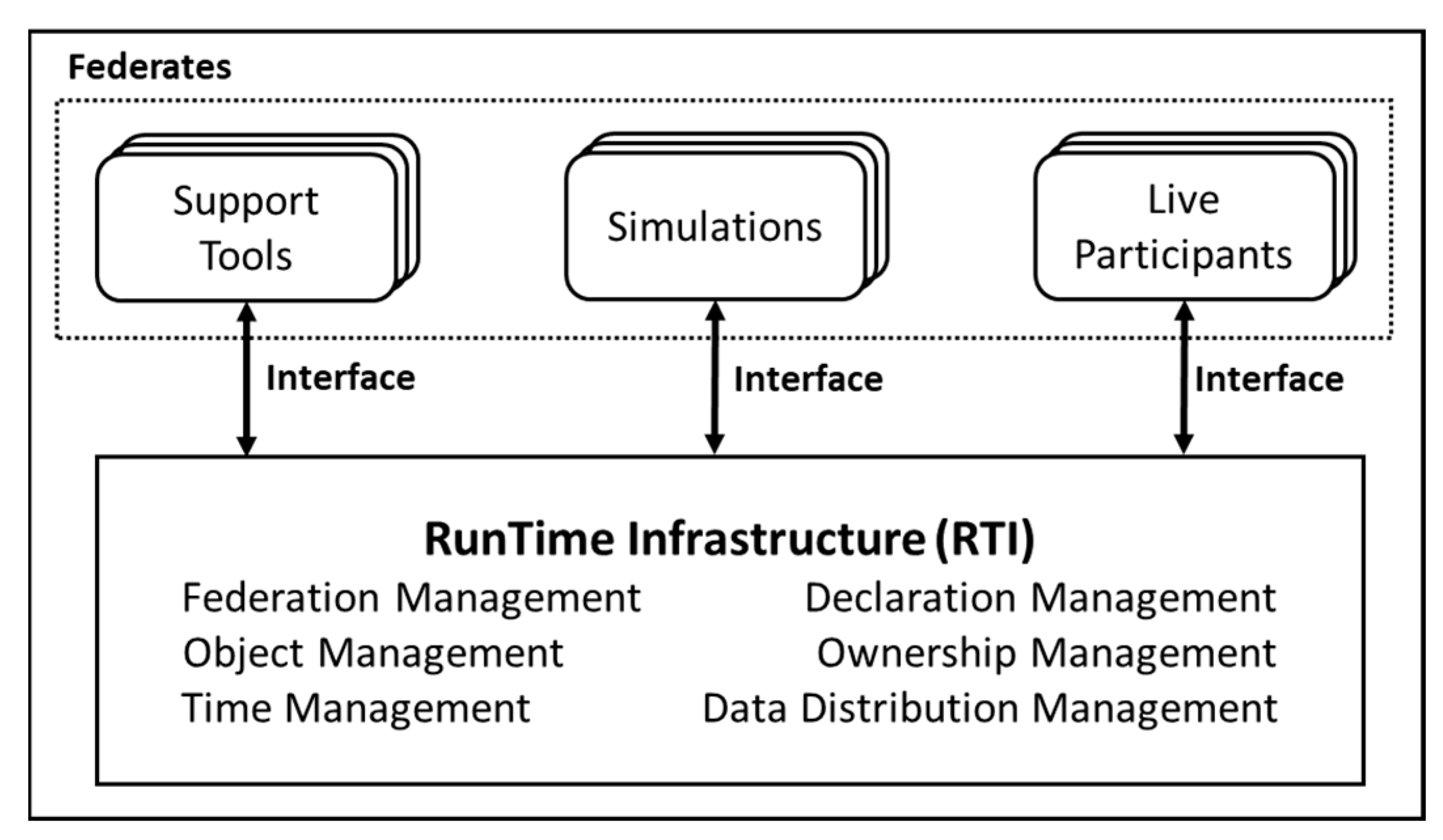
Figure 2 shows how the HLA federation is split into key functional parts. The first part is the federates, which can be a computer simulation, a simulator, a supporting utility, or even an interface for a live player or instrumented range. The HLA does not impose restrictions on what is expressed in the federation or how it is expressed. Still, it must integrate the functions specified in all federates so that objects in the simulation can interact with other simulated objects through data exchanges supported by services in the RTI. The second one is RTI. The RTI is a distributed operating system for the federation. The RTI provides a set of services that support simulation when performing these federation-to-federation interactions and federation management functions. The last part is the runtime interface. The HLA runtime interface specifications provide a standard way for federates to interact with the RTI, call RTI services to support runtime interactions between federates, and respond to requests from the RTI. This interface is independent of the implementation and independent of the specific object model and data exchange requirements of all federations [26].
Unlike other architectures, HLA is not intended for a specific type of model, such as constructive models for ALSP [28] or virtual models for SIMNET and DIS [29], or a specific class of applications, such as test and training range applications for TENA [30]. Instead, the HLA is designed to provide a universal distributed simulation architecture for all types of models and applications, including training, acquisition, analysis, experiment, engineering, testing and evaluation. The HLA supports all LVC models and has unique capabilities for real-time and logical-time execution [31].
3. Systematic Review Method
To examine the MRM implementation studies related to the LVC system and to determine research directions for future endeavors, we conducted a systematic literature review of published papers following the guidelines set out by the Preferred Reporting Items for Systematic Reviews and Meta-Analyses (PRISMA) [32].
3.1. Study Selection
We performed an unbounded search for articles. Our study selection was based on the premise that the MRM research used actual defense simulation models, not theoretical or conceptual models. This is because the purpose of this review is to analyze the role of the MRM in establishing actual LVC systems. The literature had to provide a practical experience wherein two different resolution models are connected to meet the MRM conditions. In other words, not only should the high-resolution model (HRM) and the low-resolution model (LRM) be distinguished from each other, but also how these models are interlocked and what protocol was used to communicate between these models should be specified.
The following databases were used to search the papers reviewed for this study:
- Ei Compendex (Engineering village);
- IEEE Xplore;
- ABI/INFORM (ProQuest);
- Google Scholar.
The search keywords were selected to find all studies about MRM using defense models. A duplicate search was conducted to capture as many papers as possible. The keywords included all related terms mentioned in chapter 2.1, except for “selectable resolution modeling”, because only one study used the term “selectable resolution modeling”, and this study was about MRM [4]. In the screening phase, unrelated or duplicated papers were excluded. To search the publications corresponding with our intention, we used four strings for each database, with the following:
- “multi resolution modeling”
- “multi resolution combat”
- “cross resolution modeling”
- “variable resolution modeling”
The keywords were applied to the title and full text.
3.2. Review Process
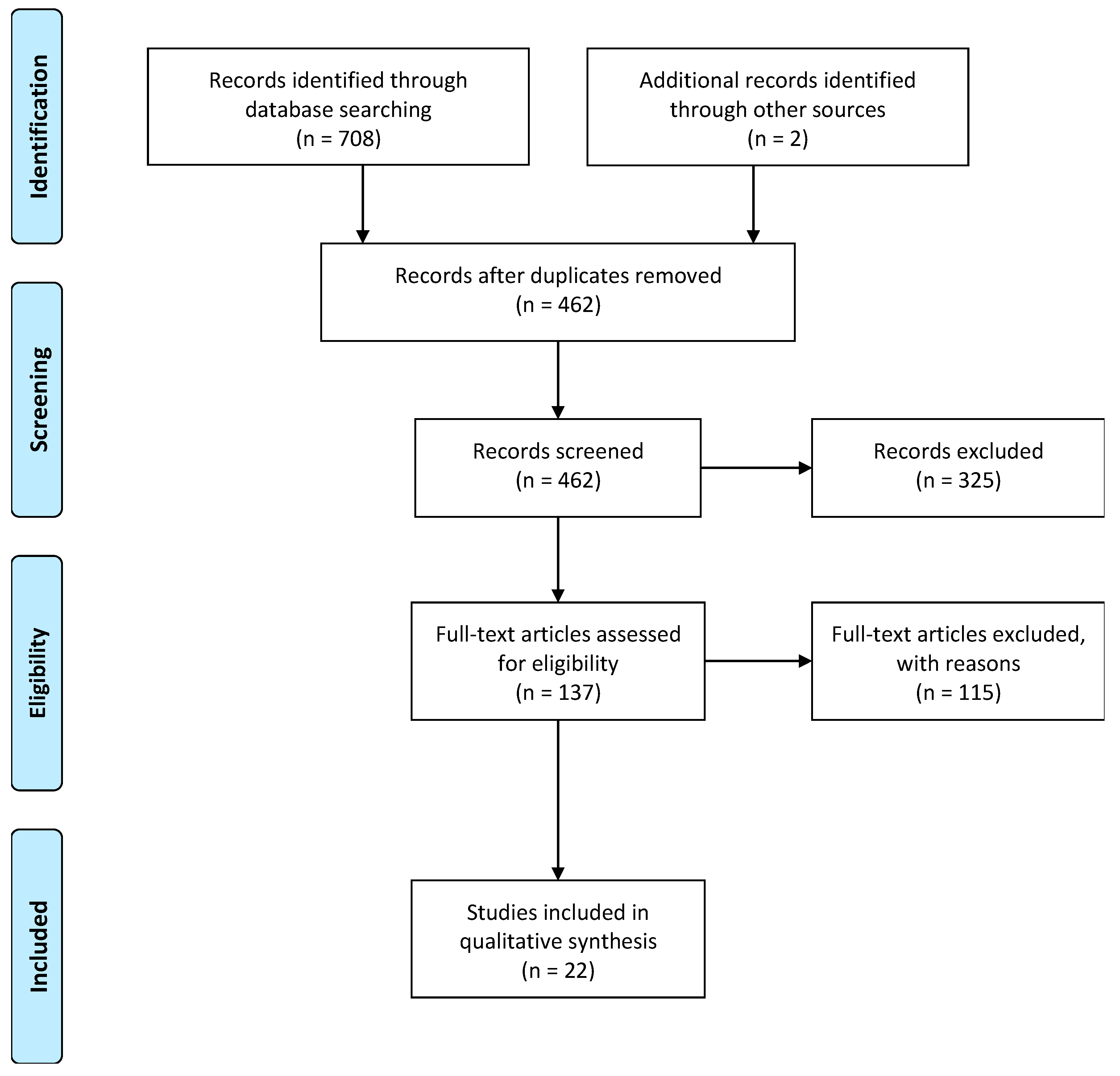
The initial search showed 708 articles. There were two additional articles which were written in Korean. The reason for including these two studies is that they are entirely consistent with our intention. After the screening and eligibility appraisal, 137 articles were identified as the defense MRM research. Except for the studies that utilized conceptual and theoretical models, 22 studies that are directly related to the MRM implementation for integrating LVC systems were included in this review. A flow diagram summarizing this process is shown in Figure 3.
4. Results
4.1. Major MRM Implementations
The first study for the MRM implementation was published in 1992, and the study that used the term “MRM” for the first time was published in 1993. Including these papers, a total of 20 different MRM implementation studies have been identified. The details of these significant MRM implementation studies are shown in Table 2. Each experiment used the LRM and HRM separately for their project, and the suitable simulation architecture used for interoperability was described in each article.
In the beginning, the systems developed, such as Eagle and SIMNET, were mainly used for experimentation. The Eagle is the LRM developed by the US Army, and SIMNET is the first distributed simulation interoperability standard and the first fully functional protocol developed by the US DoD [52]. However, since 2010, the development of computer technology has led to the use of commercial off-the-shelf (COTS) combat software, such as VR-Forces, MASA and SIMbox. VR-Forces and MASA are constructive simulations, while SIMbox is a virtual simulation for training.
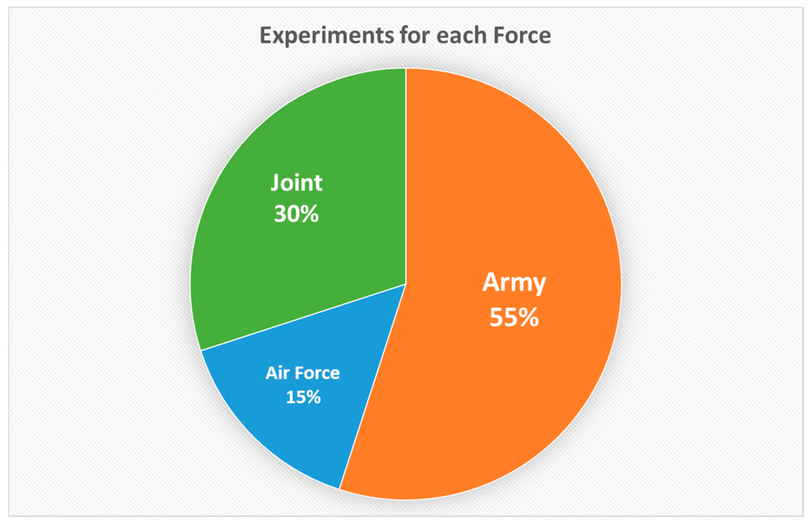
Figure 4 shows the distribution of the experiments for each force. The experiments done by the Army were the majority, followed by the Joint and the Air Force. There was no study of the Navy alone. An analysis of these results will be discussed later.
4.2. Interoperation Structures of Major MRM Experiments
The selected 22 studies were scrutinized in this review. These studies built various structures to conduct experiments for the MRM and LVC systems. Except for two studies that are basic research for the other studies, a total of 20 experiments were included. In these experiments, the actual simulation platforms were used and interconnected to explore issues related to LVC integration and resolution difference. The specific structures and distinctions of each experiment are summarized in this chapter, and the issues commonly found are discussed in the next chapter.
Ref. [33,34] conducted the first simulation integration, which was the integrated Eagle/BDS-D project. The Eagle system was a company- and battalion-level simulation developed by the US Army Training and Analysis Command (TRAC). The goal of the Eagle/BDS-D project was the integration of the Eagle and SIMNET simulations. The Institute for Simulation and Training (IST) has created a Computer Generated Forces (CGF) Testbed that generates and controls individual entities in the SIMNET world. The Los Alamos National Lab (LANL) developed the Simulation Integration Unit (SIU). The SIU takes information about individual entities from the SIMNET Protocol Data Units (PDUs), which is processed and integrated by the SIU before transmission to the Eagle. Figure 5 illustrates how those systems are interconnected.
Ref. [35] created the Eagle II prototype that is a distributed combat model composed of the Eagle, the SIMNET/Semi Automated Forces (SAF), the SIU, and a visualization program (NPSNET) as described in Figure 6. Since the Eagle Ⅱ prototype could not use real the SIMNET simulator hardware, a method for providing three-dimensional visualizations in high-resolution areas that are typically available in these simulators was required. They used the term “MRM” for the first time, emphasizing its importance. This study is meaningful in that it used the SAF, not the CGF.
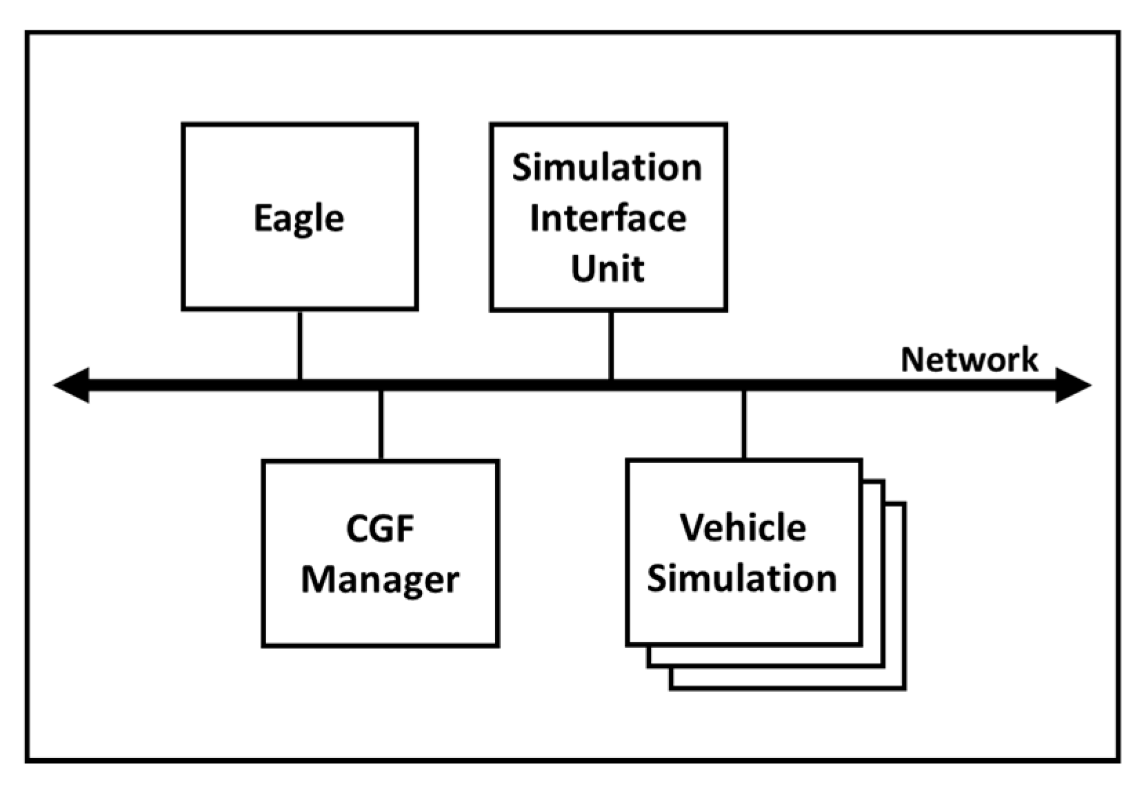
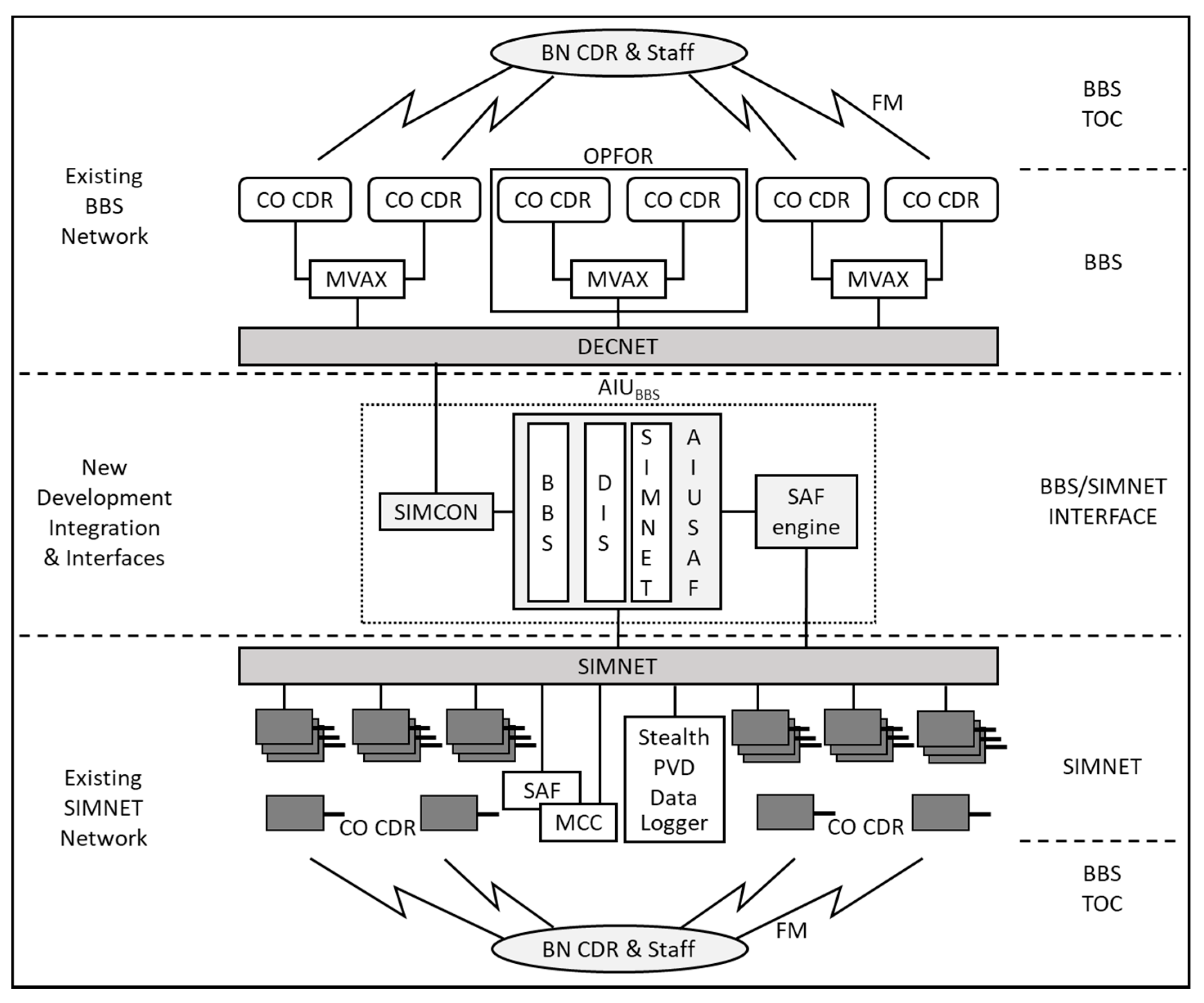
Ref. [36] conducted the Brigade/Battalion Battle Simulation (BBS)/DIS project to explore the issues surrounding the integration of constructive and virtual simulators. As shown in Figure 7, the BBS was chosen as a constructive system. Since a DIS compatible simulation was not available at the time, the SIMNET-compatible Semi-Automated Forces (SAF) was selected for a virtual system. The BBS Advanced Interface Unit (AIU) was built to support communication with the BBS and the SIMNET/SAF system. The BBS AIU consists of three main components: the AIU, the SAF engine, and the Simulation Control (SIMCON). The AIU delivers interfaces between the time-stepped and real-time simulations. The SAF engine performs the modeling of disaggregated entities. On the other hand, SIMCON is a software that offers an interface into the BBS common area. The experiment related to aggregation and disaggregation was not included in this study.
Ref. [37] implemented the interconnection of the Virtual SOF Inter-Simulator Network (SOFNET) aircraft simulator and the Joint Conflict Model (JCM) theater-level constructive simulation. The interoperability is accomplished using the DIS PDU. Figure 8 shows the structure connecting the two systems that exist in different locations. They used the Network Interface Unit (NIU) to regulate the data intercommunicated. Terrain correlation issues due to the differences in the resolution were identified, and they attempted to solve the problems by creating a terrain-following algorithm. This interface helped with mission reviews and mission rehearsal training.
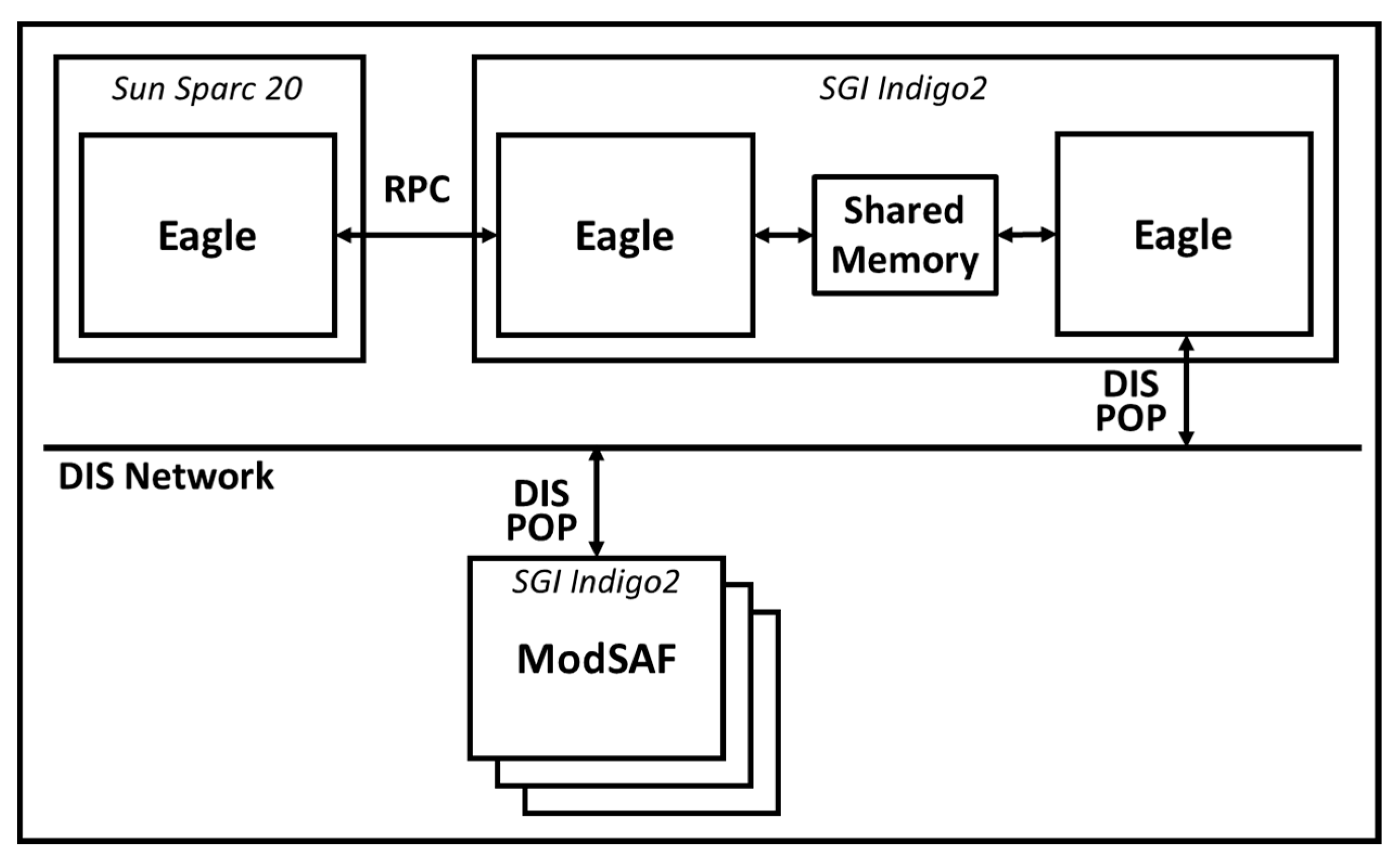
Refs. [38,39] implemented a dynamic aggregation and disaggregation process in the Joint Precision Strike Demonstration (JPSD) program. The purpose of this program was to conduct technical research that could contribute to the defense arena. The Corps Level Computer Generated Forces (CLCGF) system was created by integrating the Eagle constructive simulation with the Modular Semi-Automated Forces (ModSAF) entity-level simulation. The SIU manages the resolution changes. The ability of the CLCGF to make dynamic resolution changes efficiently is enabled by three key design decisions: to tightly couple the SIU to ModSAF (Figure 9), to represent all of Eagle’s units in ModSAF as aggregates, and to require that Eagle units be simulated at the company (or battery) level. They addressed the issue that dynamic aggregation and disaggregation is one of the keys to supporting large-scale DIS exercises.
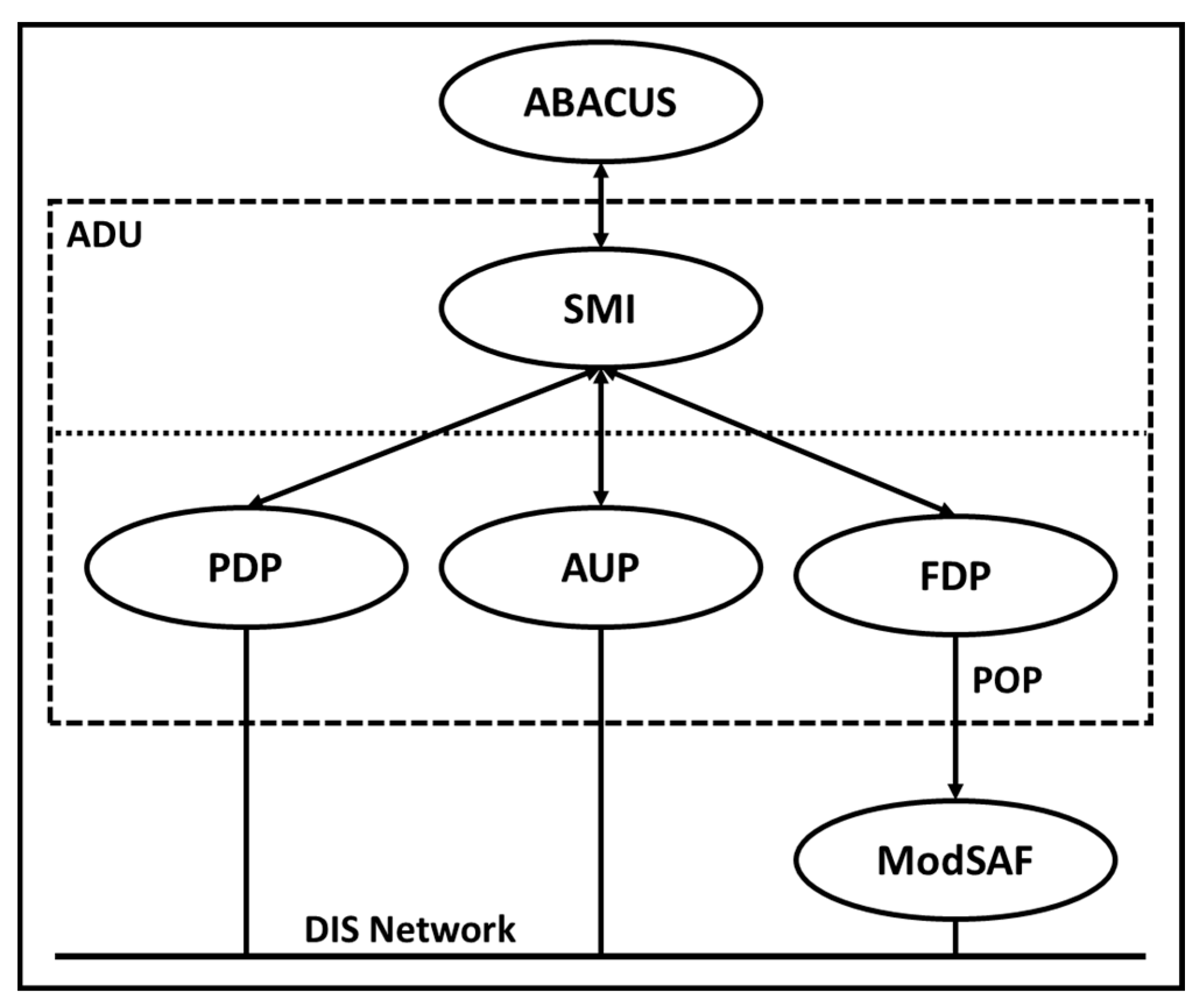
Ref. [40] conducted the aggregation and disaggregation research by developing a linkage between the UK Army’s Advanced Battlefield Computer Simulation (ABACUS) and the ModSAF. They investigated the benefits and problems of this connection, and techniques for achieving interoperability between different levels of the resolution systems. A software module known as the Aggregation Disaggregation Unit (ADU) was used to translate the data for the appropriate simulation. As shown in Figure 10, the ADU consists of four logical elements: the simulation management interface (SMI), the pseudo-disaggregation process (PDP), the aggregate update process (AUP), and the full disaggregation process (FDP). The SMI analyzes the ABACUS messages to gain information on simulated units and requests updated messages at an appropriate time before ABACUS starts its time step update. The PDP and AUP were coded as one for efficiency. The PDP retains a list of entities that are being simulated and sends this information to shared memory for access by the FDP and AUP. The FDP initializes all required ModSAF libraries and creates a local copy of the first database created by the ModSAF.
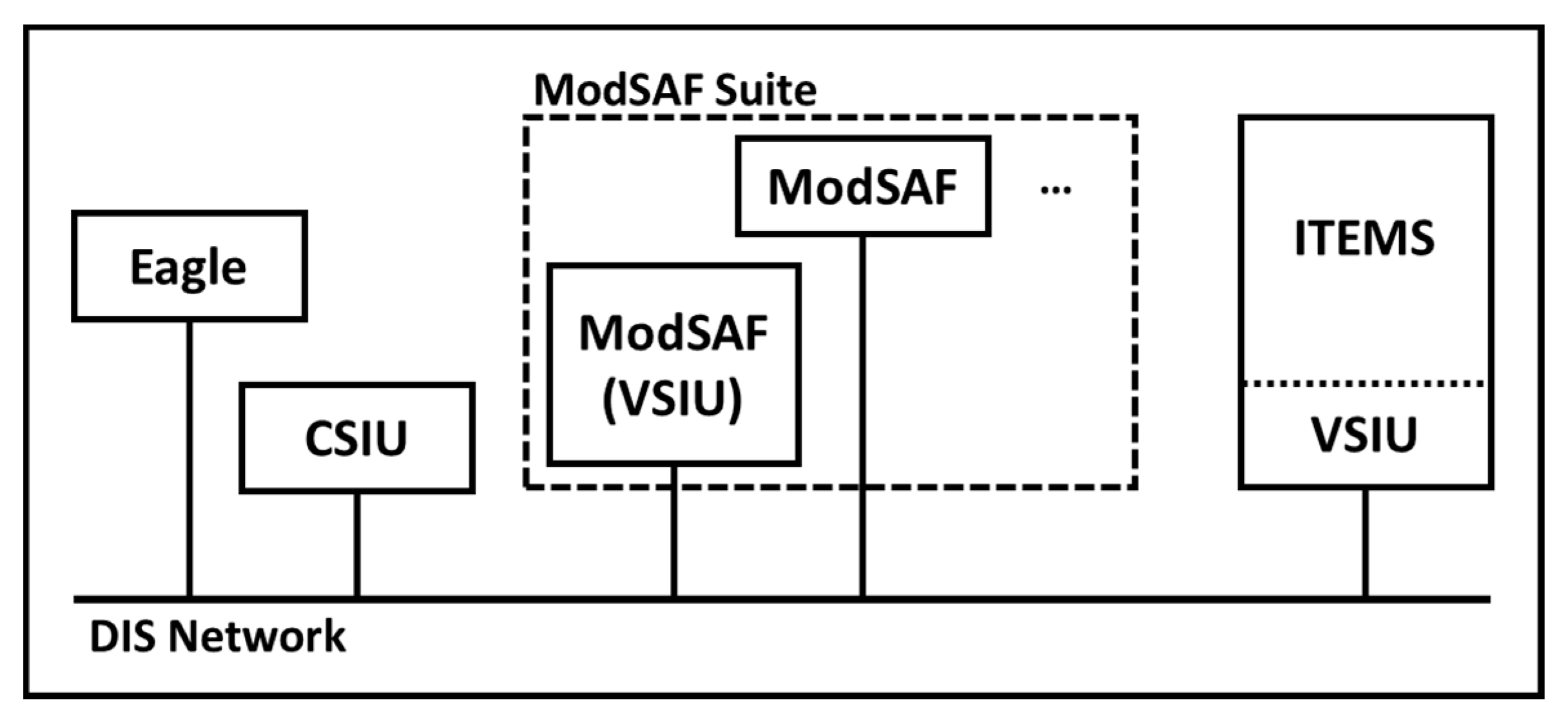
Ref. [41] presented an architecture for connecting multiple aggregate-level wargame simulations to multiple virtual components. They linked the Eagle aggregate simulation with the ModSAF and ITEMS using a DIS network, as shown in Figure 11. ITEMS is a UNIX process that can run on Silicon Graphics workstations. The Eagle Constructive Simulation Interface Unit (CSIU) provides the functionality of the Aggregate Simulation Interface (ASI). The SIU communicated with Eagle via UNIX RPCs, but the CSIU can be configured to use TCP/IP or UDP network packets. The Virtual Simulation Interface Unit (VSIU) provides the functionality of the Virtual Simulation Interface (VSI) for the ModSAF and ITEMS, and communicates with ModSAF using the persistent object (PO) protocol. This attempt is viewed as a new and powerful tool for conducting analytical research, but also a way to bring legacy simulations into the virtual world.
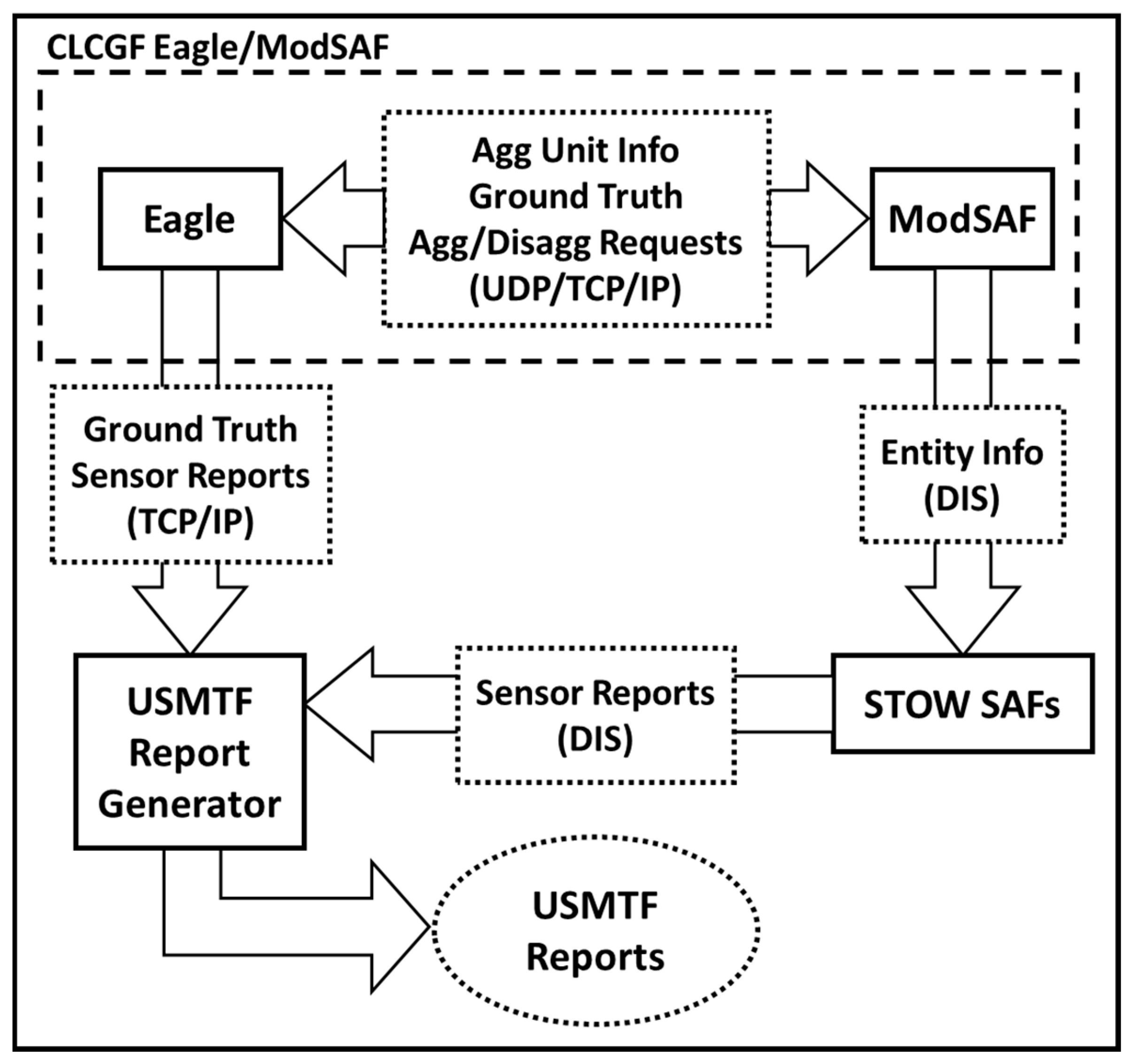
Ref. [42] performed the DARPA’s Dynamic Multi-user Information Fusion (DMIF) project related to the analysis of sensor data collected in large-scale combat. To achieve the goal of this project, the STOW SAF sensor models are integrated with Eagle and ModSAF, as shown in Figure 12. The STOW SAF is made up of the ArmySAF, AirSAF and MarineSAF. The pseudo-disaggregation was implemented within the Eagle/ModSAF linkage system that was developed initially for the CLCGF project. Through the experiments, they found that the ModSAF suite had an optimum capacity of between 2500 and 3500 pseudo-entities. They also suggested the following further pseudo-disaggregation ideas: enhancing pseudo-disaggregation realism and increasing system capacity.
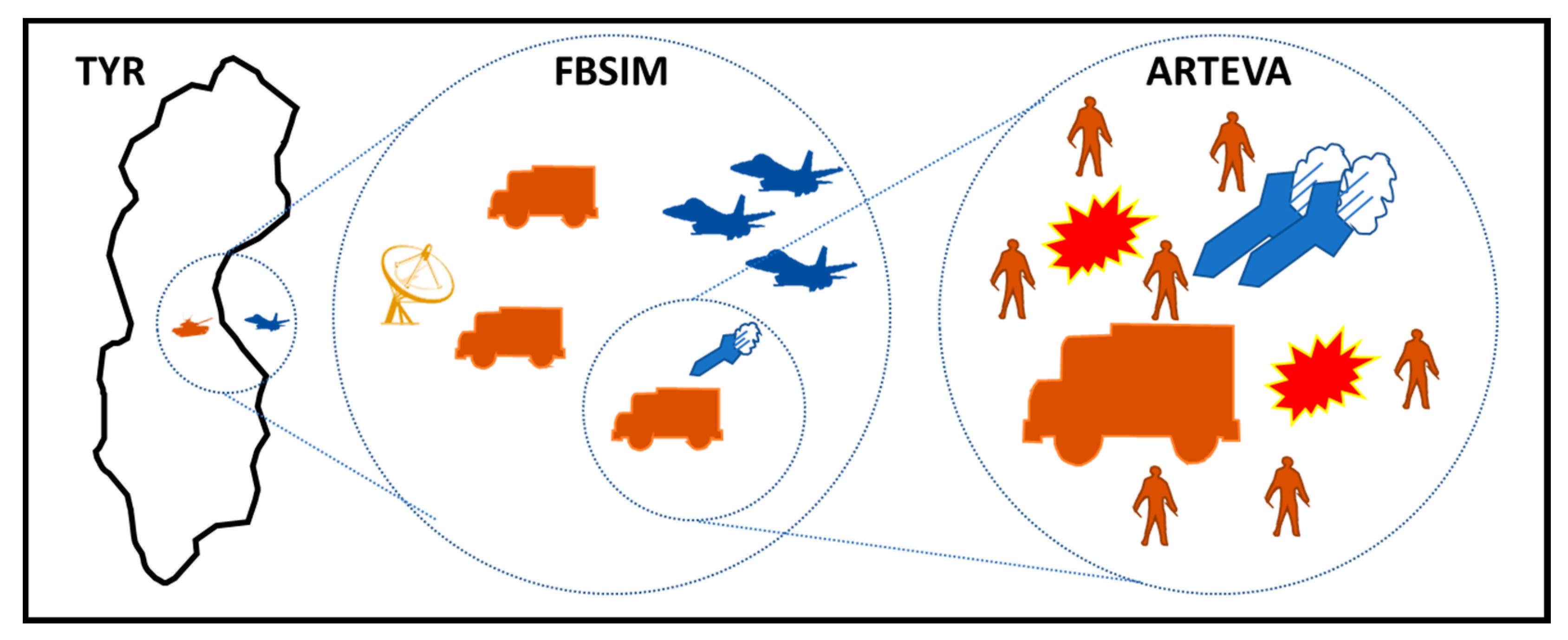
Ref. [43] describes the Swedish Defense Research Establishment project that is working on the problem of applying the HLA concept to interoperating simulation models on different levels of resolution. Three legacy models were used to build a federation: ARTEVA, FBSIM and TYR. The ARTEVA is a stochastic model for technical-level battle. The FBSIM is a unit-level simulation that models a higher aggregation level unit than the ARTEVA. TYR is a simulation engine to support the command and decision-making training of senior officers and staff. The aggregation and disaggregation strategies are illustrated in Figure 13. They pointed out the data inconsistency and fidelity problems that occur when using models on different resolutions.
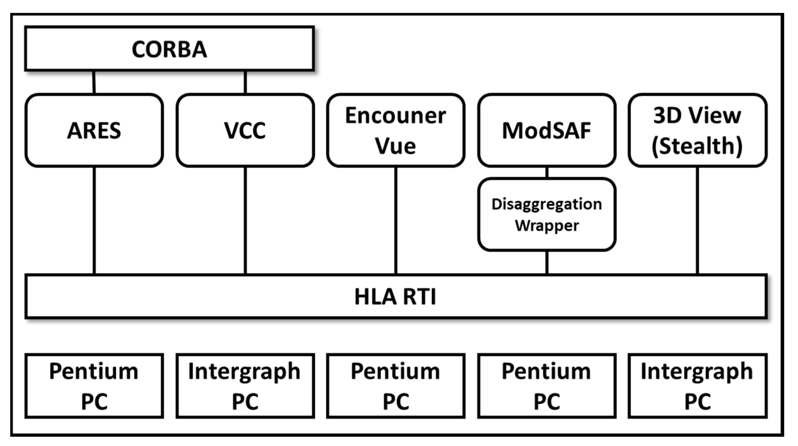
Ref. [44] implemented a study to build the battlespace federation using HLA and the federation is described in Figure 14. The aggregate-level simulation, Advanced Regional Exploratory System (ARES), was used as a campaign-level model to interoperate with the ModSAF. The Virtual Command Center (VCC) provides a point-and-click interface to interact with the unit as well as showing the commander’s view of the combat. Some issues related to the aggregation and disaggregation were reported. The author pointed out that the unit model needs to maintain more information about its entity status for data consistency.
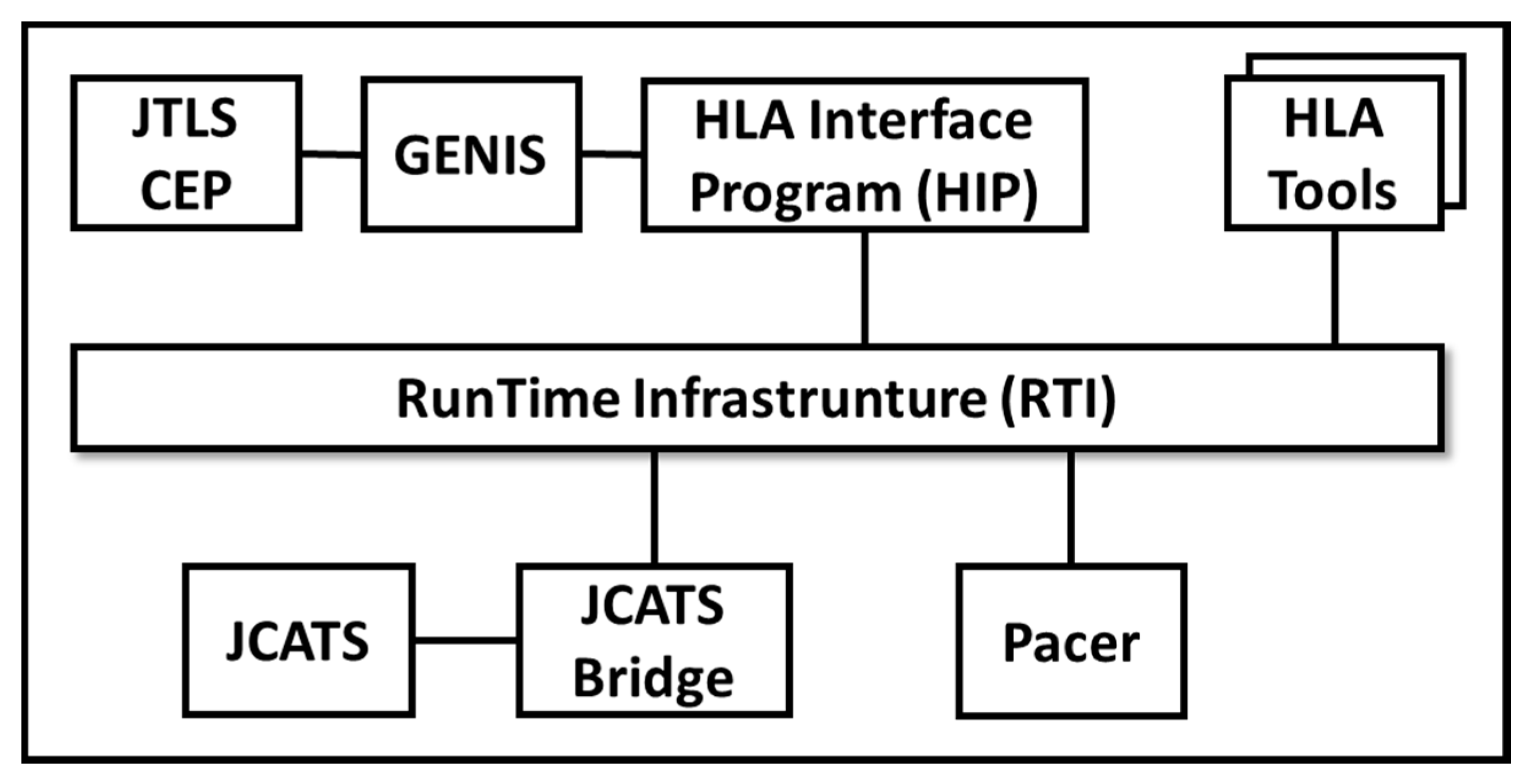
Ref. [45] built a federation to link the Joint Theater Level Simulation (JTLS) with the Joint Conflict and Tactical Simulation (JCATS) using the HLA. The JTLS is a unit-level simulation used for supporting the analysis of operational plans. The JCATS is an entity-level simulation developed for training. JTLS-JCATS federation architecture is described in Figure 15. They used a shared object ownership method to avoid repeated changes to the number of units passed from JTLS to JCATS. They also emphasized the importance of using early FEDEP work.
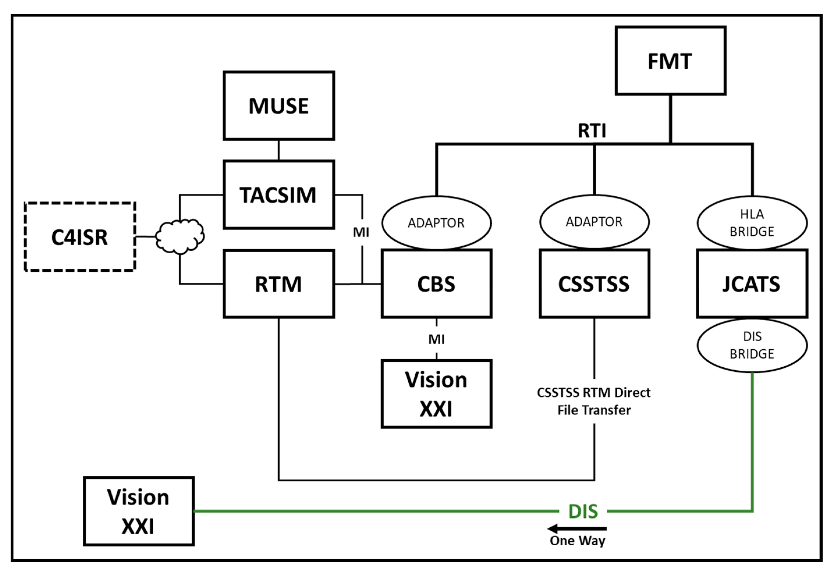
Ref. [46] presented the Army Constructive Training Federation–Multi-Resolution Modeling (ACTF-MRM) architecture. The Program Executive Office (PEO) creates the ACTF-MRM for simulation, training and instrumentation (STRI). As shown in Figure 16, the federation consists of the Corps Battles Simulation (CBS), the Combat Service Support Training Simulation System (CSSTSS), and the JCATS. These were connected using four interfaces: HLA, DIS, CBS Master Interface (MI), and point-to-point. Both TACSIM and the runtime manager (RTM) receive data for the aggregate units through the MI. They create an algorithm referred to as FLUD, which is a mechanism that converts CBS aggregates into representations of platforms and squads. This ACTF-MRM can solve the issues concerning the inconsistent representation of individual vehicles and squads in the Command, Control, Communication, Computers, Intelligence, Surveillance, and Reconnaissance (C4ISR) systems.
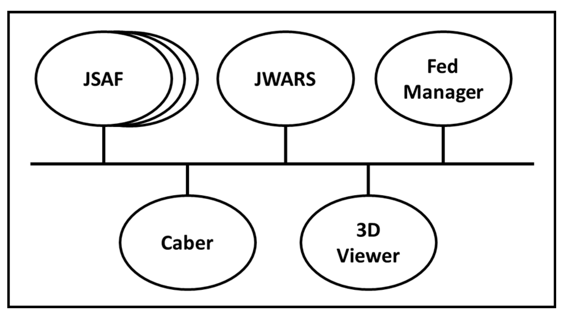
Ref. [47] performed an experiment that develops an HLA federation using the Joint Warfare System (JWARS) and the Joint Semi-Automated Forces (JSAF), as depicted in Figure 17. The JWARS was used as the campaign-level low-resolution simulation, and the JSAF was utilized as the mission-level high-resolution simulation. The operating states were divided into three: fully aggregated (FA), disaggregated (DA) and pause state. The pause state is used for ensuring simulations stay synchronized at a reasonable level. The adaptability of the JWARS and JSAF models to handle other federation object models (FOMs) can gradually enhance the federation by adding a variety of systems.
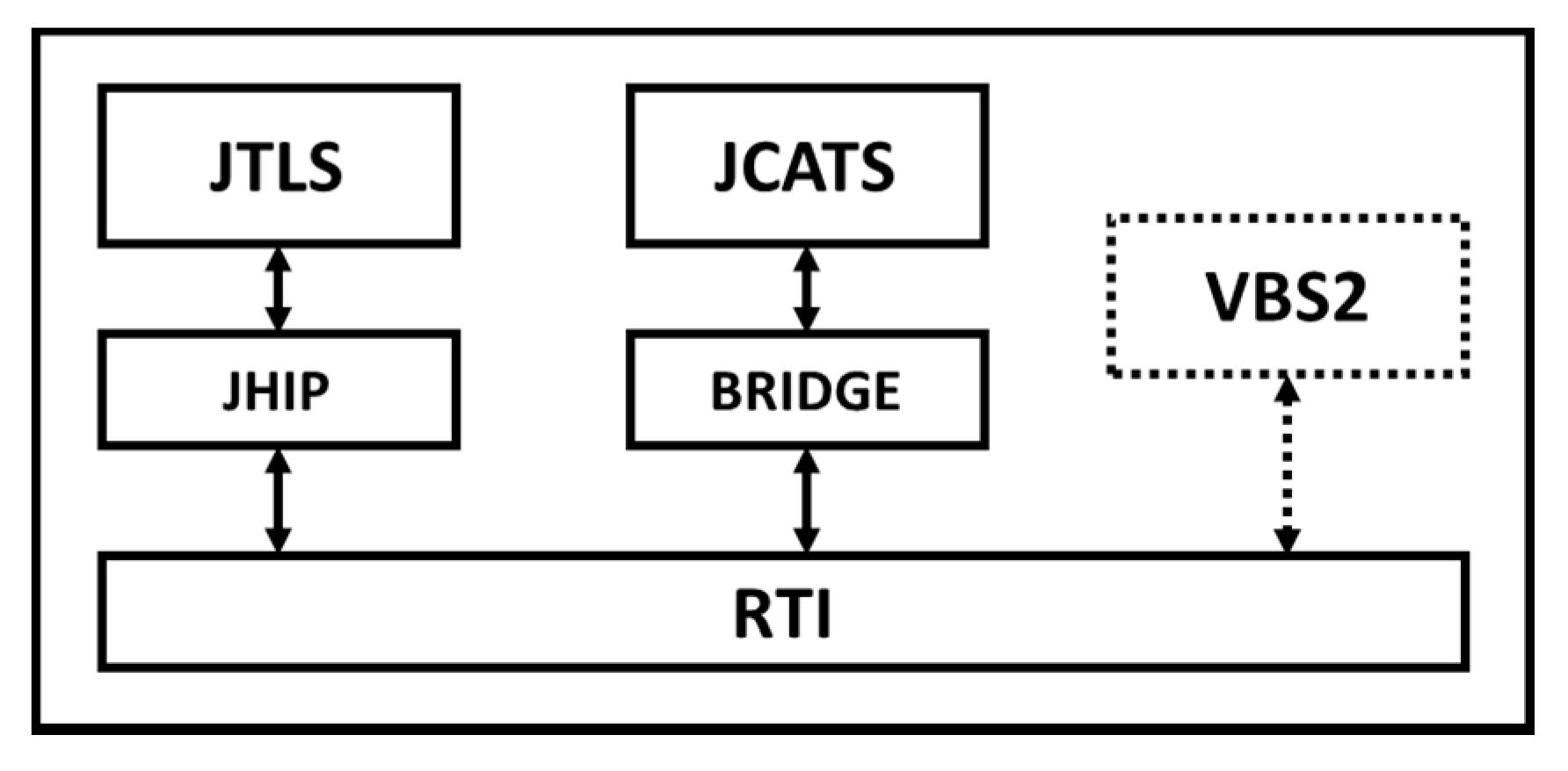
Ref. [48] performed the NATO training federation (NTF) project that developed an HLA federation using the JTLS and JCATS, as shown in Figure 18. The NTF was successfully used in a major NATO exercise for the first time in 2008. The Virtual Battle Simulation (VBS2) provides intelligence, such as aerial photography and video streams of unmanned aerial vehicles (UAVs), to help the training audience gain better insight into decision making.
Ref. [49] implemented a dynamic MRM using an HLA protocol. They used the COTS simulations to build a federation. The MASA Sword, a simulation platform for military training from the platoon- to battalion-level, was used as the aggregated simulation, and VR-Forces, a CGF platform for entity and unit model simulation, was utilized as the entity-level simulation. Figure 19 shows the aggregate unit and disaggregated entities at the same time. Both are COTS simulations. This study found that the latest simulated COTS products built using existing interoperability standards can communicate efficiently and realistically.
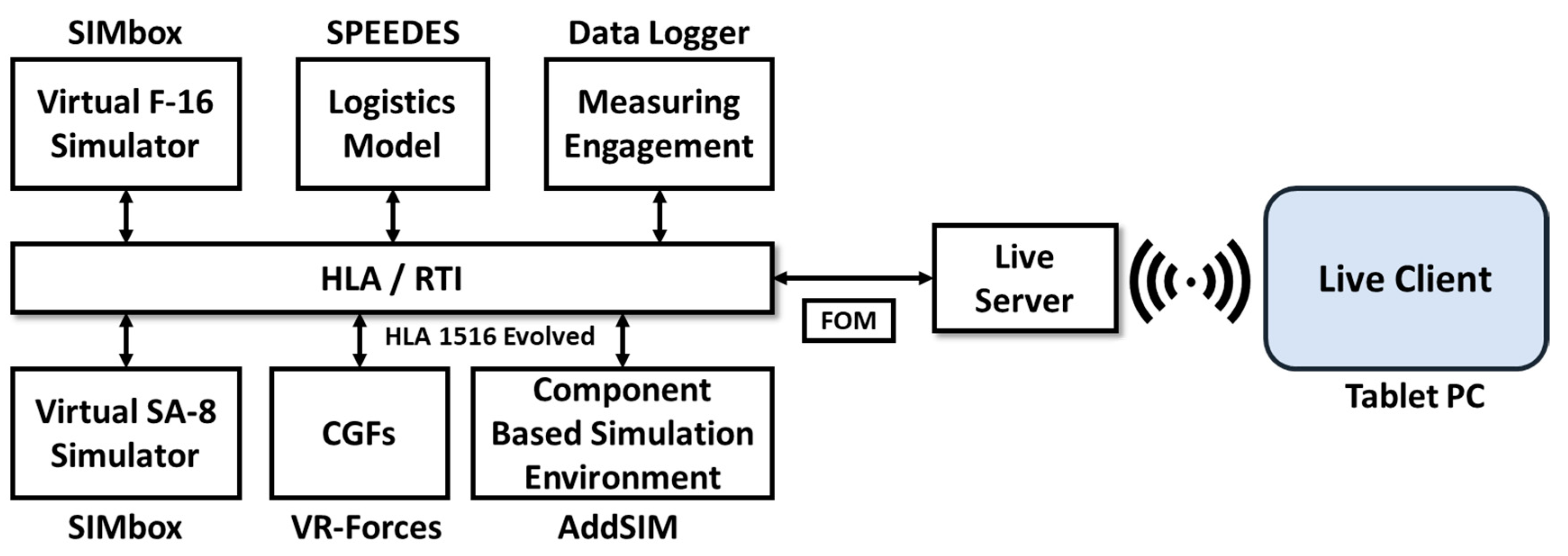
Ref. [50] presented an experimental LVC simulation framework. The SIMbox from SIMIGON was employed as a virtual flight and an anti-air missile simulator. VR-Forces was used as a constructive simulation. The SIMbox is a high-resolution simulator for the training of F-16 pilots. The AddSIM, which is a component-based simulation developed by the Agency of Defense Development in South Korea, participated in the simulation framework as a federate, as illustrated in Figure 20. Furthermore, they utilized a tablet PC as the live component for the experimental LVC simulation framework. This work helps one understand the design concepts of the LVC simulation system.
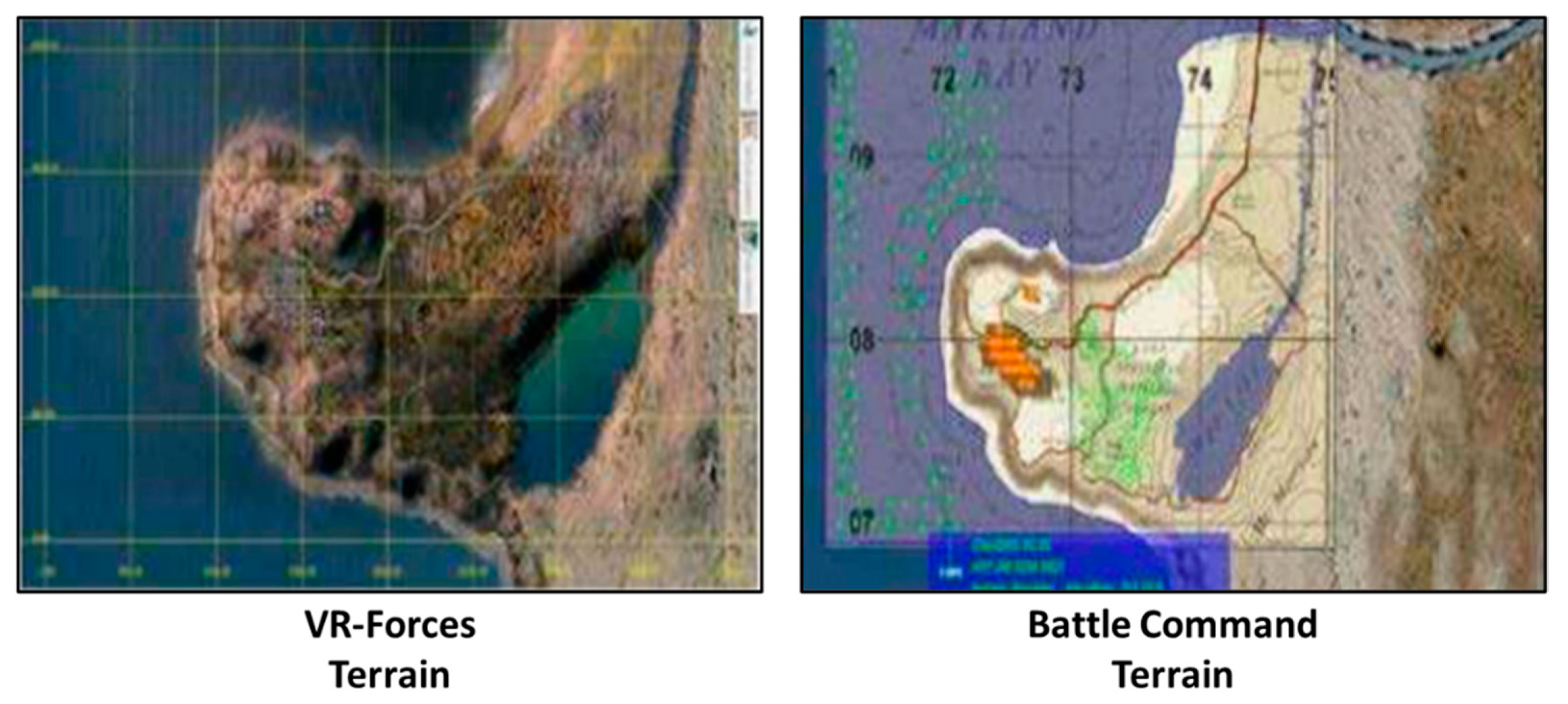
Ref. [10] conducted the MRM experiment using COTS simulations. The Battle Command was used for executing a unit-level simulation, and VR-Forces was utilized as an entity-level simulation. Primarily, they emphasized the importance of geographic data consistency when building the MRM federation. All geospatial data and map feature data are coordinated through the terrain generation tool to ensure that geographic information for entities is always suitable during the simulation, as shown in Figure 21.
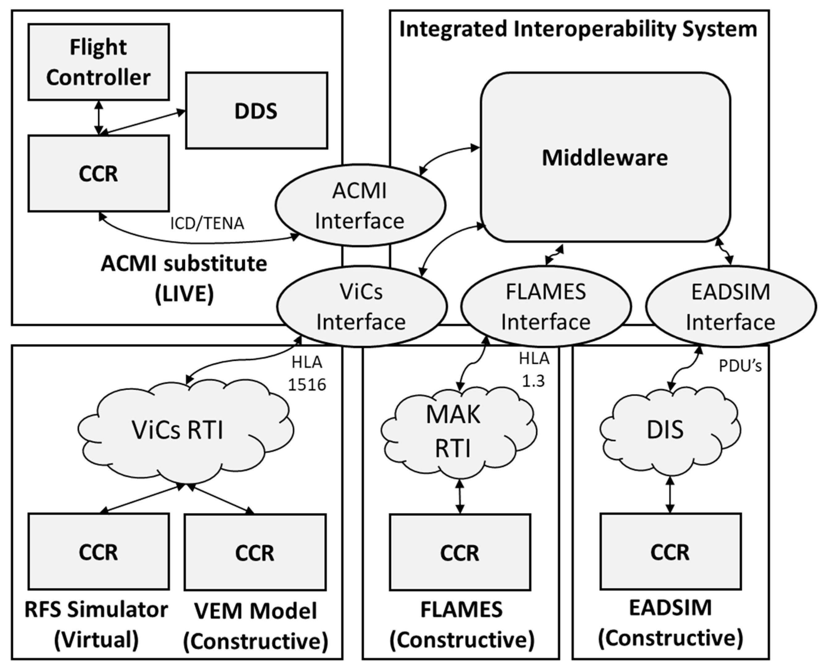
Ref. [22] developed the integrated system for LVC and conducted Verification and Validation (V&V) study of the aircraft weapon system. They linked the Flexible Analysis, Modeling and Exercise System (FLAMES), the Extended Air Defense Simulation (EADSIM), the Reconfigurable Flight Simulator (RFS) and the Aircraft Combat Maneuvering Instrumentation (ACMI), as described in Figure 22. The FLAMES and EADSIM are constructive simulations, the FRS is a virtual simulator, and the ACMI is the live training system. They utilized an unmanned model aircraft as the ACMI substitute. Three different scenarios and V&V test were conducted. The “MRM” was not mentioned in this study because differences in the resolution were not compared. This study is meaningful in that the LVC integration is successfully implemented.
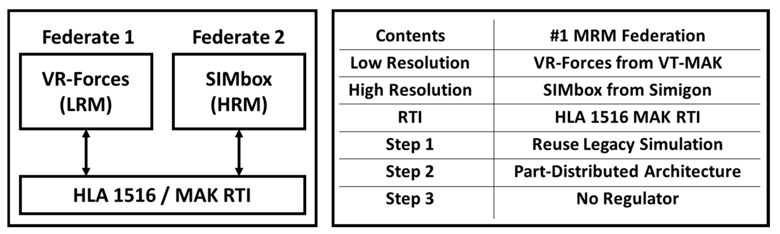
Ref. [3] built an MRM federation using the VR-Forces and SIMbox using an HLA architecture. VR-Forces was used as the LRM, and the SIMbox was used as the HRM. The federation configuration is shown in Figure 23. Two experiments were performed to analyze the phenomenon associated with the resolution difference. The engagement scenario was developed to investigate the interaction between objects created in each system. They found that the database gap could limit the representation of entities, and that all federation systems should have a common understanding to communicate with each other.
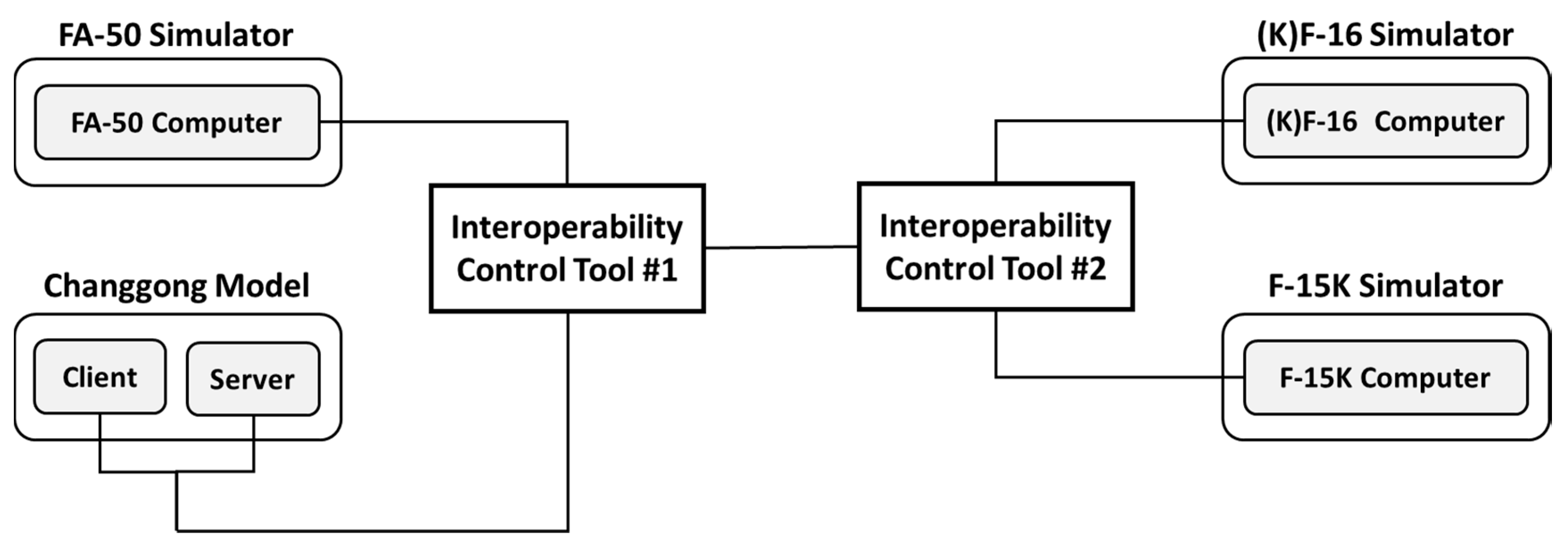
Ref. [51] performed the Virtual-Constructive (VC) system interlock test using the Air Force fighter simulators and War Game model. The F-15K, KF-16 and FA-50 simulators were connected to a unit-level Changgong model, as depicted in Figure 24. This study is valuable in that the platforms currently being used were connected to communicate with each other, and the feasibility of the Air Force LVC training system was confirmed through this. The term “MRM” was not mentioned in this research, but some limitations that have been identified, such as object visualization issues, are strongly related to the MRM issues. Furthermore, to make a larger battlefield, resolution conversion is necessary, and the need for the MRM must be emphasized accordingly.
5. Discussion
This review includes almost all experiments that have built MRM for LVC systems with actual military platforms. Research using the defense model and simulation is very limited due to the nature of the military field. In addition, connecting and interacting with different platforms with different resolution levels is a very complex and challenging task. Although not many studies have been published, it has been confirmed that the MRM is a very crucial technique for integrating LVC systems because each component of the LVC systems has a different resolution.
Expressing the battlefield with diverse resolutions means that it can provide arrange of combat information. It gives not only the specific data needed for detailed missions by using the HRM, but also gives overall battlefield information for the campaign level by using the LRM. Maximizing the advantages of such diverse resolutions is the primary purpose of the MRM.
In accordance with the research direction, some of the items and certain issues analyzed through this review are discussed in this chapter.
5.1. V-C Interoperation
Most of the experiments include only the virtual and constructive system, not the live system. In the military field, the live system means the actual weapon system, that includes a tank, ship, and fighter, and architectures such as TENA, have been developed to link the live systems. There was only one article that used the actual live system, which was the experiment wherein the data link system called ACMI was utilized to link the live system with the virtual and constructive systems by installing the model aircraft, not the real fighter [22].
The MRM was more focused on the VC interoperation. While interlocking the live system is very limited, the VC linkage can make applications more practical, such as training and simulation. For example, if the virtual simulators that are far away are networked and various scenarios are conceived and operated with the constructive system, not only can they perform practical training, but they can also rehearse for tasks that are difficult to do for safety reasons. In this linkage, MRM is essential to address issues arising from differences in resolution between the systems. MRM resolves the data differences in each object that originate in resolution differences and can lead to errors, such as the failure of objects in other systems linked to each platform, to demonstrate them adequately [3].
5.2. Different Resolution Standard
The resolution standard of engagement level may vary depending on the characteristics of each force. As shown in Table 3, the size of the battlefield and the number of aggregation levels depend on what the central combat entity of each force is. In the case of the Army, there can be many levels of aggregation, such as platoon, company, battalion, brigade, division, and so on, because the combat entity is based on a soldier. On the other hand, in the other forces there can be only a few levels of aggregation, such as a fleet or squadron, because the combat entities in the Navy and Air Force are based on ships and aircraft.
Aggregation level is also related to the size of the battlefield. The larger the size of the battlefield, the more the Army needs to implement an aggregation, as compared to the Navy or Air Force. Because of the relatively large number of troops, it is necessary to convert to the LRM to promptly understand the battlefield situation, which is why the MRM is essential. Experiments on actual resolution conversion were conducted only on the Army, and there was no study conducting resolution changes on the Navy and Air Force.
5.3. MRM Implementation Issues
Various theoretical and practical tasks related to the development and use of the MRM have been identified through this review. A lot of studies have been conducted since then, but specific issues consistently arise in the MRM implementation. These technical challenges must be addressed for LVC integration because they can interact with each other and cause bigger problems. Several representative problems are discussed here, such as disaggregation overload, time synchronization, correlation, and data inconsistency.
5.3.1. Disaggregation Overload
Disaggregation means the conversion from low resolution to high resolution in the MRM implementation. In MRM, disaggregation is mainly performed by triggers such as time, location, or commander. In some circumstances, the number of disaggregated entities can be too large for some parts of the system, such as the computational or storage capacity, or the bandwidth of the network [53,54]. This phenomenon is mainly due to the chain reaction of disaggregation. If a close encounter with an entity results in disaggregation, this event may spread to the other units in the adjacent area [55]. This disaggregation overload can have a huge impact on the entire system, so it needs to build a system with sufficient capacity to fit the desired scenario.
5.3.2. Time Synchronization
Almost all high-resolution (entity-level) models execute in real-time to enable interoperation with weapon simulators. On the other hand, low-resolution (unit-level) models generally run as fast as possible because the size of the simulated time step has nothing to do with the time required to compute the events of that time step [56]. Therefore, in MRM, the passage of time in the two models must be reconciled. If not, events resulting from the interaction of the two models would proceed at different rates in each platform. As a result of this, serious realism breakdowns can potentially occur. For example, if a tank model that appears to have already been destroyed in one simulation might still be displayed as alive in the other simulation, this tank is capable of carrying out an attack against an enemy vehicle even though it is in a state of being destroyed and unable to attack. This can cause errors, leading to a decline in the reliability of the simulation. Therefore, specific definitions for time synchronization must be performed through the interface module.
5.3.3. Results Correlation
Typically, the simulation results of a structured scenario are independent of the resolution level [56]. However, there is the possibility that errors in the correlation of the results occur due to various factors. For example, discrepancies can occur due to differences in terrain representations or the motion of models, which can have a significant impact on scenario results.
This issue is fundamental in invalidity questions regarding the correlation between low and high resolution [15,16,57]. Some studies have also highlighted the importance of this issue, which uses the terms consistency of prediction, or only consistency [15,16,58,59].
The simulation results should be consistent no matter what models of resolution are used, so the result correlation must be verified to secure the validation of the MRM federation.
5.3.4. Data Inconsistency
The data inconsistency is the difference in data between the HRM and LRM, which is a vital issue in the MRM. Almost all MRM studies regard this problem as the most important one [3,4,5,9,10,15,60,61,62].
This issue is caused by differences in the amount of information when aggregation or disaggregation is performed. In particular, it happens when aggregation or disaggregation is performed again after disaggregation or aggregation. The information in each entity that is simulated only with high resolution may differ from that of the entities that are aggregated into a unit and then disaggregated back.
The interface module can be used to keep a consistency of data when aggregation or disaggregation occurs. Integrating information from entities to a unit is more accessible than decomposing the data of a unit into each entity. Furthermore, the MRE method of maintaining all information pertaining to the entity can solve this problem [63]. Still, it is not a practical solution because building a model that keeps all information about the entity is very difficult in military M&S.
5.4. The Comparison of Civilian and Military
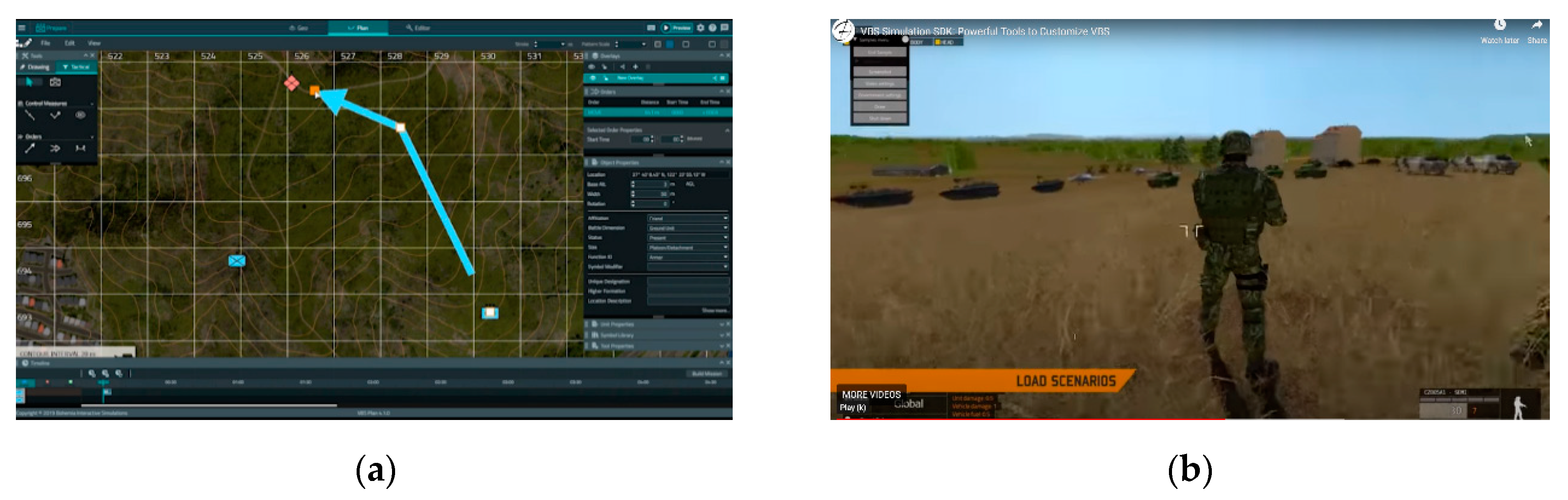
When the MRM study was first started, there were a lot of problems that occurred due to a lack of technical skills, such as memory, graphics, CPU, and so on. Implementing the model with multiple resolutions was very difficult in complex military simulation, and most of the research about MRM was conceptual and theoretical. Now, though, most of them are entirely operable because of the advances in computer technology. The simulation software that has been developed in civilian companies recently has the ability to represent the objects at different levels of resolutions. For instance, in the VBS4 that was launched in 2020 by Bohemia Interactive Simulations (BISim), the resolution levels of the object models are an interchangeable option, and the user can choose the desired resolution at any time, as depicted in Figure 25.
Despite this trend, the reason why research on MRM is necessary pertains to the legacy simulations in use for integrating the LVC system in the military, as discussed earlier. It is more economical to utilize various models already developed by the military than to create new models that support multi-resolution functions. In addition, the often-emphasized security issue in military operations could be another reason. Few papers using actual military simulations have been published recently, but what we have learned through this review is that the LVC integration is still in progress, and there are still several issues to be solved. Therefore, the MRM is consistently recognized as a crucial technology in the military field.
6. Conclusions and Future Work
This paper presented the results from a systematic review of the MRM studies for integrating the LVC system. The 20 major MRM implementation studies were analyzed, based on interoperability architecture, to give the answers to the two questions addressed in the introduction.
Firstly, as we mentioned in the Discussion, integrating the LVC systems is still in its infancy. Therefore, the MRM research into this has also been primarily focusing on the VC connection. In some ways, the concept of MRM is straightforward, which is the representing of an object at various levels of resolution. The issue, though, is what architecture will be used and how it will be expressed, as well as what type of combat model and weapon system will be simulated. In this respect, the studies using actual simulation platforms that have been reviewed in this paper (not theoretical or conceptual studies) have very important implications.
Secondly, we have discussed not only what research and technology challenges are involved in MRM implementation, but also how important these challenges are to the LVC systems. However, since commercial platforms that support the transition of model resolution have been developing in the civilian domain, the answer to the second question might be controversial. As a matter of fact, it may be more visually effective to utilize these commercial platforms in limited situations, such as the demonstration of the MRM in VC interoperation. However, considering the situation in which the HRM data of numerous live assets, such as soldiers, are expressed as the company in LRM on the commander’s screen, it is unquestionable that the MRM implementation issues mentioned in the discussion must be resolved.
In a nutshell, the scientific contribution of this paper is that it presents future directions through the review of the past and present of MRM in the military field, which entails answers to the two questions initially proposed. The key point is that it interprets the need for MRM, especially in the military filed, from the perspective of the challenge of LVC integration.
In addition to this, as the reliance on MRM integrating LVC systems grows, there is a possibility that concerns about the reliability of the MRM will grow. This means that the additional verification and validation (V&V) process must be performed on the resolution difference, even though each model interoperated in MRM has been verified. The research on the V&V process should be carried out continuously, to ensure that the MRM is trusted, which will lead to successful LVC systems.
Author Contributions
Conceptualization, K.L.; methodology, K.L.; validation, K.L., G.L. and L.R.; investigation, K.L.; resources, K.L.; data curation, K.L.; writing—original draft preparation, K.L.; writing—review and editing, L.R.; visualization, K.L.; supervision, G.L. and L.R. All authors have read and agreed to the published version of the manuscript.
Funding
This research received no external funding.
Conflicts of Interest
The authors declare no conflict of interest.
References
- Hong, S.Y.; Kim, T.G. A resolution converter for multi-resolution modeling/simulation on HLA/RTI. In Systems Modeling and Simulation; Springer: Tokyo, Japan, 2007; pp. 289–293. [Google Scholar]
- Davis, P.K.; Tolk, A. Observations on New Developments in Composability and Multi-Resolution Modeling. In Proceedings of the IEEE Winter Simulation Conference, Washington, DC, USA, 9–12 December 2007; pp. 859–870. [Google Scholar]
- Kim, J.; Lee, K.; Marin, M.; Lee, G.; Rabelo, L. Development of the Multi-Resolution Modeling Environment through Aircraft Scenarios. In Proceedings of the SAE Aerospace Systems and Technologies Conference, London, UK, 6–8 November 2018. [Google Scholar]
- Davis, P.K.; Bigelow, J.H. Experiments in Multiresolution Modeling (MRM); Rand Corporation: Santa Monica, CA, USA, 1998. [Google Scholar]
- Hong, S.Y.; Kim, T.G. Specification of multi-resolution modeling space for multi-resolution system simulation. Simulation 2013, 89, 28–40. [Google Scholar] [CrossRef]
- Liu, B.; Huang, K. The Concept and Some Design Issues about Multi-Resolution Modeling in HLA; ICSC: Shanghai, China, 2002. [Google Scholar]
- Liu, B.; Huang, K. Multi-resolution modeling: Present status and trends. J. Syst. Simul. 2004, 16, 1150–1154. [Google Scholar]
- Santucci, J.F.; Capocchi, L.; Zeigler, B.P. System entity structure extension to integrate abstraction hierarchies and time granularity into DEVS modeling and simulation. Simulation 2016, 92, 747–769. [Google Scholar] [CrossRef]
- Jie, F.; Li, F.; Lu, Z.; Geng, B. Study of CGF Task Simulation System Based on HLA. In Proceedings of the International Computer Science Conference, Shanghai, China, 27–30 October 2012; pp. 361–369. [Google Scholar]
- Rabelo, L.; Kim, K.; Park, T.W.; Pastrana, J.; Marin, M.; Lee, G.; Nagadi, K.; Ibrahim, B.; Gutierrez, E. Multi resolution modeling. In Proceedings of the IEEE Winter Simulation Conference, Huntington Beach, CA, USA, 6–9 December 2015; pp. 2523–2534. [Google Scholar]
- Yang, B.; Ren, B.; Wu, Y. The research of multi-resolution modeling and simulation of the emergency evacuation. Proc. Eng. 2012, 29, 3110–3116. [Google Scholar] [CrossRef] [Green Version]
- Gorecki, S.; Possik, J.; Zacharewicz, G.; Ducq, Y.; Perry, N. A multicomponent distributed framework for smart production system modeling and simulation. Sustainability 2020, 12, 6969. [Google Scholar] [CrossRef]
- Li, H.; Li, K.; Yuan, L.; Liu, Y. Research on Multi-Resolution Modeling of Intercity Railway Train Control System. In Proceedings of the International Conference on Intelligent Rail Transportation (ICIRT), Marina Bay Sands, Singapore, 12–14 December 2018; pp. 1–5. [Google Scholar]
- Davis, P.K. An Introduction to Variable-Resolution Modeling and Cross-Resolution Model Connection; Rand Corporation: Santa Monica, CA, USA, 1993. [Google Scholar]
- Reynolds, P.F.; Natrajan, A.; Srinivasan, S. Consistency maintenance in multiresolution simulation. ACM Trans. Model. Comput. Simul. (TOMACS) 1997, 7, 368–392. [Google Scholar] [CrossRef]
- Davis, P.K. An introduction to variable-resolution modeling. Naval Res. Logist. (NRL) 1995, 42, 151–181. [Google Scholar] [CrossRef]
- Page, E.H.; Smith, R. Introduction to military training simulation: A guide for discrete event simulationists. In Proceedings of the IEEE Winter Simulation Conference, Washington, DC, USA, 13–16 December 1998; pp. 53–60. [Google Scholar]
- Tolk, A. Engineering Principles of Combat Modeling and Distributed Simulation; Wiley Online Library: Hoboken, NJ, USA, 2012; p. 61. [Google Scholar]
- Park, T.W.; Kim, K.; Rabelo, L.; Lee, G. An Agile Roadmap for Live, Virtual and Constructive-integrating Training Architecture (LVC-ITA): A Case Study Using a Component Based Integrated Simulation Engine. Ph.D. Thesis, University of Central Florida, Orlando, FL, USA, 2015. [Google Scholar]
- Loper, M.L. Modeling and Simulation in the Systems Engineering Life Cycle: Core Concepts and Accompanying Lectures; Springer: Berlin/Heidelberg, Germany, 2015. [Google Scholar]
- MSCO. Modeling and Simulation (M&S) Glossary; Modeling and Simulation Coordination Office: Alexandria, VA, USA, 2011. [Google Scholar]
- Oh, J.; Jang, Y.C.; Kim, C.Y.; Jee, C.K.; Hong, Y.S. V&V of integrated interoperability system for LVC simulation on aircraft weapon system. J. Korea Inst. Mil. Sci. Technol. 2015, 18, 326–334. [Google Scholar]
- Tan, G.; Ng, W.N.; Moradi, F. Aggregation/Disaggregation in HLA Multi-Resolution Distributed Simulation. In Proceedings of the 5th IEEE International Workshop on Distributed Simulation and Real-Time Applications, Cincinnati, OH, USA, 13–15 August 2001; p. 76. [Google Scholar]
- Lee, G.; Kim, J.; Marin, M.; Lee, K.; Gutierrez, E.; Rabelo, L. Building Multiple Resolution Modeling Systems Using the High-Level Architecture. SAE Int. J. Adv. Curr. Pract. Mobil. 2019, 2, 838–842. [Google Scholar] [CrossRef]
- Steinman, J.S.; Hardy, D.R. Evolution of the Standard Simulation Architecture; Ram Labs Inc.: San Diego, CA, USA, 2004. [Google Scholar]
- Dahmann, J.S.; Fujimoto, R.M.; Weatherly, R.M. The Department of Defense High Level Architecture. In Proceedings of the IEEE 29th Conference on Winter Simulation, Atlanta, GA, USA, 7–10 December 1997; pp. 142–149. [Google Scholar]
- IEEE. IEEE Standard for Modeling and Simulation (M&S) High Level Architecture (HLA)-Framework and Rules; IEEE Std 1516-2010 (Revision of IEEE Std 1516–2000); IEEE: Piscataway, NJ, USA, 2010; pp. 1–38. [Google Scholar] [CrossRef]
- Wilson, A.L.; Weatherly, R.M. The aggregate level simulation protocol: An evolving system. In Proceedings of the 26th Conference of Winter Simulation, Orlando, FL, USA, 11–14 December 1994; pp. 781–787. [Google Scholar]
- Hofer, R.C.; Loper, M.L. DIS today [Distributed interactive simulation]. Proc. IEEE 1995, 83, 1124–1137. [Google Scholar] [CrossRef]
- Powell, E.T.; Noseworthy, J.R.; Tolk, A. The test and training enabling architecture (TENA). In Engineering Principles of Combat Modeling and Distributed Simulation; Wiley Online Library: Hoboken, NJ, USA, 2012; p. 449. [Google Scholar]
- Kuhl, F.; Weatherly, R.; Dahmann, J. Creating Computer Simulation Systems: An Introduction to the High Level Architecture; Prentice Hall PTR: Upper Saddle River, NJ, USA, 1999. [Google Scholar]
- Moher, D.; Liberati, A.; Tetzlaff, J.; Altman, D.G.; Group, P. Preferred reporting items for systematic reviews and meta-analyses: The PRISMA statement. PLoS Med. 2009, 6, e1000097. [Google Scholar] [CrossRef] [PubMed] [Green Version]
- Karr, C.; Franceschini, R.; Perumalla, K.; Petty, M. Integrating battlefield simulations of different granularity. In Proceedings of the Southeastern Simulation Conference, Pensacola, FL, USA, 22–23 October 1992; pp. 48–55. [Google Scholar]
- Karr, C.R.; Franceschini, R.W.; Perumalla, K.R.S.; Petty, M.D. Integrating Aggregate and Vehicle Level Simulations. In Proceedings of the Third Conference on Computer Generated Forces and Behavioral Representation, Institute for Simulation and Training, Orlando, FL, USA, 17–19 March 1993; pp. 231–240. [Google Scholar]
- Powell, D.R.; Hutchinson, J.L. Eagle II: A Prototype for Multi-Resolution Combat Modeling; Los Alamos National Lab.: Los Alamos, NM, USA, 1993. [Google Scholar]
- Hardy, D.; Healy, M. Constructive and virtual interoperation: A technical challenge. Simul. Ser. 1994, 26, 37. [Google Scholar]
- Babcock, D.; Molnar, J.; Selix, G.; Conrad, G.; Castle, M.; Dunbar, J.; Gendreau, S.; Irvin, T.; Uzelac, M.; Matone, J. Constructive to Virtual Simulation Interconnection for the Sofnet-JCM Interface Project. In Proceedings of the 16th Interservice/Industry Training Systems and Education Conference; National Training and Simulation Association, Orlando, FL, USA, 28 November–1 December 1994. [Google Scholar]
- Calder, R.B.; Peacock, J.C.; Panagos, J.; Johnson, T.E. Integration of Constructive, Virtual, Live, and Engineering Simulations in the JPSD CLCGF. In Proceedings of the 5th Conference on Computer Generated Forces & Behavioral Representation; Institute for Simulation Training, Orlando, FL, USA, 9–11 May 1995. [Google Scholar]
- Calder, R.B.; Peacock, J.C.; Wise, B.P., Jr.; Stanzione, T.; Chamberlain, F.; Panagos, J. Implementation of a Dynamic Aggregation/Deaggregation Process in the JPSD CLCGF. In Proceedings of the 5th Conference on Computer Generated Forces & Behavioral Representation; Institute for Simulation Training, Orlando, FL, USA, 9–11 May 1995. [Google Scholar]
- Weeden, N.; Smith, M. Aggregation Disaggregation research-A UK Approach Update. In Proceedings of the 15th DIS Workshop, Orlando, FL, USA, 16–20 September 1996; pp. 305–314. [Google Scholar]
- Schricker, S.A.; Franceschini, R.W.; Stober, D.R.; Nida, J.D. An Architecture for Linking Aggregate and Virtual Simulations. In Proceedings of the Sixth Conference on Computer Generated Forces & Behavioral Representation, Institute for Simulation Training, Orlando, FL, USA, 23–25 July 1996; pp. 427–434. [Google Scholar]
- Schricker, S.A.; Franceschini, R.W.; Adkins, M.K. Using Pseudo-Disaggregation to Populate a Large Battlefield for Sensor Systems. In Proceedings of the 7th Conference on Computer Generated Forces & Behavioral Representation, Orlando, FL, USA, 12–14 May 1998; pp. 475–484. [Google Scholar]
- Seiger, T.; Holm, G.; Bergsten, U. Aggregation/Disaggregation Modeling in HLA-Based Multi Resolution Simulations. In Proceedings of the Fall Simulation Interoperability Workshop (SISO), Orlando, FL, USA, 17–22 September 2000; pp. 17–22. [Google Scholar]
- Beeker, E.R. Battlespace Federation: An HLA Experiment in Disaggregation. In Proceedings of the Spring Simulation Interoperability Workshop (SISO), Orlando, FL, USA, 26–31 March 2000; pp. 21–31. [Google Scholar]
- Bowers, A.; Prochnow, D.L. Multi-resolution modeling in the JTLS-JCATS Federation. In Proceedings of the Fall Simulation Interoperability Workshop (SISO), Orlando, FL, USA, 14–19 September 2003. [Google Scholar]
- Zabek, A.; Henry, H.; Prochnow, D.; Wright, M. The Army Constructive Training Federation–Multi-Resolution Modeling: The Next Generation of Land Component Commander Training at the Unit of Employment Echelon of Command. In Proceedings of the Fall Simulation Interoperability Workshop, (SISO), Orlando, FL, USA, 19–24 September 2004; pp. 19–24. [Google Scholar]
- Macannuco, D.; Snow, C.; Painter, R.D.; Jones, J.W. Multi-Level Resolution Engagement Modeling through a JWARS-JSAF HLA Federation. In Proceedings of the Spring Simulation Interoperability Workshop, (SISO), San Diego, CA, USA, 3–8 April 2005; pp. 607–640. [Google Scholar]
- Cayirci, E. Multi-Resolution Federations in Support of Operational and Higher Level Combined/Joint Computer Assisted Exercises. In Proceedings of the IEEE Winter Simulation Conference, Austin, TX, USA, 13–16 December 2009; pp. 1787–1797. [Google Scholar]
- Raue, E.; Gallois, V. A Dynamic Multi-Resolution Model Based on HLA Interconnection of Commercial-Off-The-Shelf (COTS) Simulation Tools. In Proceedings of the NATO Modeling and Simulation Group (NMSG) Symposium, Bern, Switzerland, 13–14 October 2011. [Google Scholar]
- Kim, K.; Park, T.; Pastrana, J.; Marin, M.; Cortes, E.A.; Rabelo, L.C.; Lee, G. Modeling of Complex Scenarios Using LVC Simulation. In Proceedings of the IEEE Winter Simulation Conference, Savannah, GA, USA, 7–10 December 2014; pp. 2931–2941. [Google Scholar]
- Kim, Y.H.; Song, Y.S.; Kim, C.O. A Study on the interoperability of ROK Air Force virtual and constructive simulation. J. Korea Soc. Simul. 2019, 28, 169–177. [Google Scholar]
- Goldiez, B.F. History of networked simulations. In The Distributed Interactive Simulation Systems for Simulation and Training in the Aerospace Environment: A Critical Review, Proceedings of the Symposium on OE/Aerospace Sensing And Dual Use Photonics, Orlando, FL, USA, 17–21 April 1995; International Society for Optics and Photonics: Bellingham, WA, USA, 1995; p. 1028005. [Google Scholar]
- Williams, T.M.; Sale, N.; Smith, M.; Shakoor, A.S. Automated Variable Representation. In Proceedings of the Simulation Interoperability Workshop (SISO), Orlando, FL, USA, 14–18 September 1998. [Google Scholar]
- Trinker, A. General Architecture for Interfacing Virtual and Constructive Simulations in DIS Environment. Internal Document; Institute for Simulation and Training: Orlando, FL, USA, 1994. [Google Scholar]
- Petty, M.; Franceschini, R. Disaggregation overload and spreading disaggregation in constructive+ virtual linkages. In Proceedings of the 5th Conference on Computer Generated Forces & Behavioral Representation; Institute for Simulation Training, Orlando, FL, USA, 9–11 May 1995; pp. 103–114. [Google Scholar]
- Petty, M.D.; Franceschini, R.W.; Panagos, J. Multi-resolution combat modeling. In Engineering Principles of Combat Modeling and Distributed Simulation; Wiley Online Library: Hoboken, NJ, USA, 2012; pp. 607–640. [Google Scholar]
- Franceschini, R.W. Correlation Error in Multiple Resolution Entity Simulations. Ph.D. Thesis, University of Central Florida, Orlando, FL, USA, 1999. [Google Scholar]
- Powell, D.R. Control of Entity Interactions in a Hierarchical Variable Resolution Simulation; Los Alamos National Lab.: Los Alamos, NM, USA, 1997. [Google Scholar]
- Franceschini, R.W.; Wu, A.; Mukherjee, A. Computational Strategies for Disaggregation. In Proceedings of the 9th Conference on Computer Generated Forces & Behavioral Representation, Institute for Simulation Training, Orlando, FL, USA, 16–18 May 2000. [Google Scholar]
- Adelantado, M.; Siron, P. Multiresolution Modeling and Simulation of An Air-Ground Combat Application. In Proceedings of the Spring Simulation Interoperability Workshop (SISO), Orlando, FL, USA, 25–30 March 2001. [Google Scholar]
- Bigelow, J.H.; Davis, P.K. Implications for Model Validation of Multiresolution, Multiperspective Modeling (mrmpm) and Exploratory Analysis; Rand Corporation: Santa Monica, CA, USA, 2003. [Google Scholar]
- Yilmaz, L.; Lim, A.; Bowen, S.; Ören, T. Requirements and Design Principles for Multisimulation with Multiresolution, Multistage Multimodels. In Proceedings of the IEEE Winter Simulation Conference, Washington, DC, USA, 9–12 December 2007; pp. 823–832. [Google Scholar]
- Natrajan, A.; Reynolds, P.F., Jr.; Srinivasan, S. MRE: A flexible approach to multi-resolution modeling. ACM SIGSIM Simul. Dig. 1997, 27, 156–163. [Google Scholar] [CrossRef]
- The Bohemia Interactive Simulations. The VBS4. Available online: http://www.bisimulations.com/products/vbs4 (accessed on 27 September 2020).
Figure 1.
Concept of Multi-Resolution Modeling.

Figure 2.
Functional view of an HLA federation.

Figure 3.
PRISMA flow diagram.

Figure 4.
Comparing the experiments for each force.


Figure 6.
Eagle II architecture block diagram (adapted from [35]).
Figure 6.
Eagle II architecture block diagram (adapted from [35]).

Figure 7.
The architecture for the BBS/SIMNET integration in Europe (adapted from [36]).
Figure 7.
The architecture for the BBS/SIMNET integration in Europe (adapted from [36]).

Figure 8.
System architecture of SOFNET and JCM (Adapted from [37]).
Figure 8.
System architecture of SOFNET and JCM (Adapted from [37]).


Figure 10.
ADU structure (adapted from [40]).
Figure 10.
ADU structure (adapted from [40]).

Figure 11.
Eagle/ITEMS network configuration and implementation (adapted from [41]).
Figure 11.
Eagle/ITEMS network configuration and implementation (adapted from [41]).

Figure 12.
DMIF test/evaluation conceptual architecture (adapted from [42]).
Figure 12.
DMIF test/evaluation conceptual architecture (adapted from [42]).

Figure 13.
The federation of the TYR, FBSIM, and ARTEVA (adapted from [43]).
Figure 13.
The federation of the TYR, FBSIM, and ARTEVA (adapted from [43]).

Figure 14.
Battlespace federation of the ARES and ModSAF (adapted from [44]).
Figure 14.
Battlespace federation of the ARES and ModSAF (adapted from [44]).

Figure 15.
JTLS-JCATS federation (adapted from [45]).
Figure 15.
JTLS-JCATS federation (adapted from [45]).

Figure 16.
ACTF-MRM architecture (adapted from [46]).
Figure 16.
ACTF-MRM architecture (adapted from [46]).

Figure 17.
Federation diagram (adapted from [47]).
Figure 17.
Federation diagram (adapted from [47]).

Figure 18.
NATO training federation (Adapted from [48]).
Figure 18.
NATO training federation (Adapted from [48]).

Figure 19.
Disaggregation and aggregation implementation.

Figure 20.
Interoperability through HLA (adapted from [50]).
Figure 20.
Interoperability through HLA (adapted from [50]).

Figure 21.
Terrain coherency of COTS simulation tools (adapted from [10]).
Figure 21.
Terrain coherency of COTS simulation tools (adapted from [10]).

Figure 22.
Interconnection view of the LVC system (adapted from [22]).
Figure 22.
Interconnection view of the LVC system (adapted from [22]).

Figure 23.
MRM federation configuration.

Figure 24.
Overall hardware structure (adapted from [51]).
Figure 24.
Overall hardware structure (adapted from [51]).

Figure 25.
(a)The LRM screenshots of VBS4, (b) The HRM screenshots of VBS4 [64].
Figure 25.
(a)The LRM screenshots of VBS4, (b) The HRM screenshots of VBS4 [64].


Table 1.
Categorizing simulations based on the interaction of people and systems.
| People | Systems | Operation | Simulation |
|---|---|---|---|
| Real | Real | Real | Live |
| Real | Simulated | Simulated | Virtual |
| Simulated | Simulated | Simulated | Constructive |
| Simulated | Real | Simulated | Unmanned |
Table 2.
Major MRM Implementations.
| SYSTEM (Force) | LRM | HRM | Protocol | Module | System | Reference |
|---|---|---|---|---|---|---|
| Eagle/BDS-D (Army) | Eagle | IST CGF Testbed | SIMNET | SIU | CC | [33,34] |
| Eagle II (Army) | Eagle | SIMNET/SAF | DIS | SIU | VC | [35] |
| BBS/SIMNET (Army) | BBS | SIMNET SAF | DIS | AIU | VC | [36] |
| SOFNET-JCM (Air Force) | JCM | SOFNET | DIS | NIU | VC | [37] |
| CLCGF (Army) | Eagle | ModSAF | DIS | SIU | CC | [38,39] |
| ABACUS/ModSAF (Army) | ABACUS | ModSAF | DIS | ADU | CC | [40] |
| Eagle/ITEMS (Army) | Eagle | ModSAF ITEMS | DIS | CSIU VSIU | CC | [41] |
| Eagle/ModSAF (Army) | Eagle | ModSAF STOW | DIS | SIU | CC | [42] |
| Swedish Air Defense (Joint) | TYR FBSIM | ARTEVA | HLA | RTI | CC | [43] |
| Battlespace Federation (Army) | ARES | ModSAF | HLA | RTI | CC | [44] |
| JTLS-JCATS (Joint) | JTLS | JCATS | HLA | RTI | VC | [45] |
| ACTF-MRM (Army) | CBS | JCATS | HLA DIS | RTI, CBS MI | VC | [46] |
| JWARS-JSAF (Air Force) | JWARS | JSAF | HLA | RTI | VC | [47] |
| NATO Training Federation (Joint) | JTLS | JCATS | HLA | RTI | VC | [48] |
| COTS simulations (Army) | MASA Sword | VR-Forces | HLA | RTI | CC | [49] |
| LVC simulation interoperability (Joint) | VR-Forces | SIMbox | HLA | RTI | VC | [50] |
| COTS simulations (Army) | Battle Command | VR-Forces | HLA | RTI | CC | [10] |
| Integrated system for LVC (Joint) | FLAMES EADSIM | ACMI RFS | HLA DIS TENA | RTI | LVC | [22] |
| COTS simulations (Joint) | VR-Forces | SIMbox | HLA | RTI | VC | [3] |
| V-C Federation (Air Force) | Changgong | F-15K, KF-16, FA-50 Simulator | HLA DIS | RTI | VC | [51] |
Note. The System column indicates what type of simulations were interoperated based on LVC integration.
Table 3.
The differences in characteristics of each force.
| Army | Navy | Air Force | |
|---|---|---|---|
| Size of the battlefield (based on the entity) | Small | Medium | Large |
| Combat entity | Soldier | Ship | Aircraft |
| Number of aggregation levels | Many | Few | Few |
Note. Aggregation refers to the resolution transition, such as from a platoon to a company. The opposite is disaggregation.
Publisher’s Note: MDPI stays neutral with regard to jurisdictional claims in published maps and institutional affiliations. |
© 2020 by the authors. Licensee MDPI, Basel, Switzerland. This article is an open access article distributed under the terms and conditions of the Creative Commons Attribution (CC BY) license (http://creativecommons.org/licenses/by/4.0/).
Share and Cite
MDPI and ACS Style
Lee, K.; Lee, G.; Rabelo, L. A Systematic Review of the Multi-Resolution Modeling (MRM) for Integration of Live, Virtual, and Constructive Systems. Information 2020, 11, 480. https://0-doi-org.brum.beds.ac.uk/10.3390/info11100480
AMA Style
Lee K, Lee G, Rabelo L. A Systematic Review of the Multi-Resolution Modeling (MRM) for Integration of Live, Virtual, and Constructive Systems. Information. 2020; 11(10):480. https://0-doi-org.brum.beds.ac.uk/10.3390/info11100480
Chicago/Turabian StyleLee, Kyungeun, Gene Lee, and Luis Rabelo. 2020. "A Systematic Review of the Multi-Resolution Modeling (MRM) for Integration of Live, Virtual, and Constructive Systems" Information 11, no. 10: 480. https://0-doi-org.brum.beds.ac.uk/10.3390/info11100480
Note that from the first issue of 2016, this journal uses article numbers instead of page numbers. See further details here.