On the Performance of Battery-Assisted PS-SWIPT Enabled DF Relaying


Shaanxi Key Laboratory of Information Communication Network and Security, Xi’an University of Posts and Telecommunications, Xi’an 710121, China
*
Author to whom correspondence should be addressed.
Information 2020, 11(3), 165; https://0-doi-org.brum.beds.ac.uk/10.3390/info11030165
Submission received: 1 February 2020
/
Revised: 2 March 2020
/
Accepted: 10 March 2020
/
Published: 20 March 2020
(This article belongs to the Section Information and Communications Technology)
Abstract
:Compared with the conventional simultaneous wireless information and power transfer (SWIPT) based relaying with “harvest-then-forward” protocol, the battery-assisted SWIPT relaying is more practical and powerful due to the joint use of the harvested energy and supplementary battery. However, to the best of our knowledge, the performance of a battery-assisted power splitting (PS)-SWIPT decode-and-forward (DF) relay system has not been studied. In this paper, for a given amount of energy from the relay’s battery, we propose to maximize the outage and ergodic capacities by optimizing the static and dynamic PS ratios that rely on statistical and instantaneous channel state information (CSI), respectively, and derive their corresponding outage and ergodic capacities. Computer simulations validate our analytical results and demonstrate the advantages of the dynamic PS over the static PS in terms of the outage and ergodic capacities, as well as the energy efficiency.
1. Introduction
Wireless relaying is considered as a privileged means to enhance the spectral efficiency and extend the coverage of communication networks [1,2]. However, the development of relay networks is facing challenges, particularly the limited battery capacity of relay nodes. Recently, the energy harvesting (EH) technique has been incorporated into wireless relaying to prolong the operation time of the energy-constrained relay node [3]. While harvesting energy from solar, vibration or other physical phenomena is recognized as a practical solution, it may not provide an incessant and stable energy supply due to the randomness of nature resources [4]. Apart from the traditional EH approach, a new promising solution, i.e., simultaneous wireless information and power transfer (SWIPT), is proposed to harvest energy from an ambient radio-frequency (RF) signal via a power splitting (PS) or time switching (TS) scheme [5]. For the SWIPT based relay system, most existing works were based on the “harvest-then-forward” protocol, i.e., the transmit power of a relay only relies on the harvested energy, and various TS/PS schemes were proposed to improve the outage/ergodic capacity the performance (see [6,7,8,9,10,11,12,13] and reference therein).
However, due to the potentially severe fading of the wireless channel and the low efficiency of the energy harvester, the harvested energy at the relay may be insufficient to support its transmission. In order to address this issue, the authors of [14] proposed the “accumulated-then-forward” scheme for a decode-and-forward (DF) relay system, in which a rechargeable battery is deployed at the relay to assist the information transmission. In [15], the authors considered energy accumulation at the relay’s battery and proposed a hybrid protocol. Recently, the authors in [16,17,18,19] proposed a battery-assisted SWIPT relay system, where the relay not only can use up the harvested energy, but also may draw energy from its battery. Compared with the “accumulated-then-forward” scheme, the battery-assisted SWIPT relaying is easier to implement since it does not require energy accumulation.
In [17], the authors compared the outage performance between the PS scheme and the TS scheme for a battery-assisted SWIPT amplify-and-forward (AF) relay system. Recently, this work was extended to battery-assisted TS-SWIPT DF relays [18,19]. While the recent works have shown that the joint usage of the harvested energy along with the battery energy can greatly enhance the outage performance, there are still open challenges that need to be tackled. Firstly, the PS scheme for battery-assisted SWIPT DF relay systems has not been investigated yet and there is a lack of fundamental understanding of their performance, e.g., the outage and ergodic capacities. Secondly, we note that the existing works [17,18,19] focused on the static PS/TS scheme, where the PS/TS ratio is determined by the statistical channel state information (CSI). While it has been shown that the system performance can be further enhanced by using a dynamic PS ratio that can be adjusted based on the instantaneous CSI instead of the static one [8,11], the performance gain in battery-assisted SWIPT relay systems is not known yet. This motivates us to study the performance of dynamic PS scheme in battery-assisted SWIPT DF relay systems and compare its performance with that of a static PS scheme.
In this work, we study the performance of a battery-assisted SWIPT DF relaying, where both the static and dynamic PS ratios are considered. Our main contributions are summarized as follows.
- The static PS scheme for the battery-assisted SWIPT DF relaying is studied. In particular, for a given static PS ratio, we derive the expressions of the outage and ergodic capacities based on the statistical CSI. Using the derived results, we can determine the optimal static PS ratios that maximize the outage and ergodic capacities, respectively.
- We develop a dynamic PS scheme for the battery-assisted SWIPT DF relaying. We first derive the optimal dynamic PS ratio to maximize the outage and ergodic capacities simultaneously at each transmission slot. Using the optimal dynamic PS ratio, the expressions for the maximum outage and ergodic capacities are obtained.
- Simulation results are provided to verify our analytical results, and to compare the static and dynamic PS schemes from the following perspectives. One is to study the performance gaps (in terms of the outage and ergodic capacities) between the static and the dynamic PS schemes for a given amount of assisted energy from the relay’s battery, and the other is to see how much battery energy consumption the dynamic PS scheme could save while maintaining the same performance as the static PS scheme. In addition, we compare the achievable energy efficiency between the static and dynamic PS schemes and show how the assisted energy affects on the energy efficiency.
2. System Model
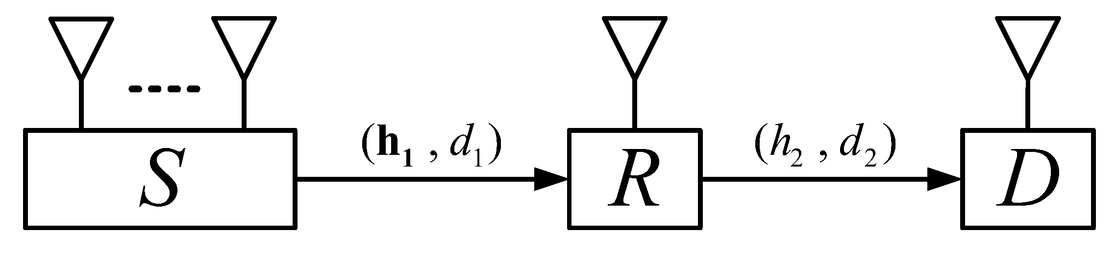
As illustrated in Figure 1, we consider a dual-hop relay system, where a source S with antennas transmits its information to a single antenna destination D via a single-antenna battery-assisted SWIPT DF relay. There is no direct link between the source and the destination. In our considered system, the relay not only runs out of the harvested energy, but also may extract the energy from its battery. Let us focus on the worst case scenario where Rayleigh fading is used to model small-scale fading over each channel [8,10,11,12,16,17,18,19], and we assume that the small-scale fading follows a complex Gaussian distribution with zero mean and unit variance. Hence, the k-th element of the channel fading vector is distributed as , where is the distance of channel; is the path loss exponent; denotes the complex Gaussian distribution. Likewise, the fading coefficient of channel follows , where is the distance of channel.
The relay follows the PS scheme in which each transmission slot is divided into two equal sub-slots. At the first sub-slot, the source S uses maximum ratio transmission (MRT) to transmit unit-energy signal to the relay R. The received signal at R from S is written as
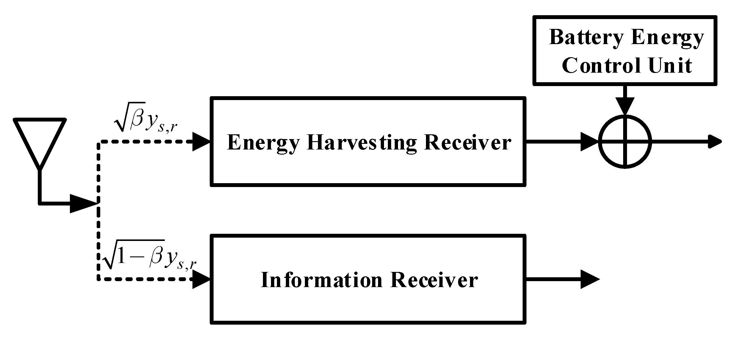
where is the transmit power of the source S, denotes the beamformer weights with conjugation operation and —norm operation , and denotes the additive white Gaussian noise with power . Meanwhile, the relay R divides the received signal into two parts through a PS ratio : for energy harvesting and for information processing. Thus the harvested energy is written as , where denotes the energy conversion efficiency and the normalized T (i.e., ) is the duration time of each transmission slot. The signal-to-noise ratio (SNR) at the relay R, , is expressed as
where denotes the input SNR.
At the second sub-slot, if the signal is successfully decoded, it will be forwarded to the destination D by the relay R. The relay extracts energy from the battery in each transmission slot to boost its transit power, as shown in Figure 2. Accordingly, the transit power at the relay is , and the SNR to decode at the destination D, , is calculated as
3. Static Power Splitting Scheme
3.1. Outage Capacity
The link is in outage when the first hop fails, or when the first hop is successful, but the second hop fails. Thus the outage probability can be written as
where denotes the SNR threshold and Y is the target rate. We define and . Then the PDF of X and Y are , and , respectively, where and . According to the above definitions, the outage probability is given as
Since the closed-form expression for (5) can not be obtained directly, the high SNR approximation derivation is as follows.
Using the Taylor series expansion for , and ignoring higher order terms of , the outage probability at high SNR regions can be written as
Based on the above definitions, can be calculated, using Equation (3.351.1) [20], as
where is the incomplete gamma function.
The second term of , , can be written as
where and . Adopting binomial expansion for , can be rewritten as
Using Equations (3.351.2) and (3.352.2) [20], can be calculated as
where with is the exponential integral function.
Similarly, using variable substitution and binomial expansion for , the third term of , , can be expressed as
Using Equations (3.351.2), (3.352.2) and (3.351.4) [20], can be calculated as
Substituting Systems (8), (11) and (13) into (7), the approximate expression for can be written as (16), as shown at the top of the next page. Accordingly, the outage capacity is calculated as
3.2. Ergodic Capacity
The ergodic capacity is expressed as
where and are the ergodic capacities corresponding to the case and , respectively [10].
and can be derived as Systems (17)–(19) and Systems (20)–(22), respectively. From , we can obtain that the range of random variable Y is . Accordingly, the ergodic capacity corresponding to is presented as (17). After solving the internal integral with respect to the variable y, (18) can be obtained. Since the integral is unbounded and there is no closed-form for (18), we use the variable substitution tan and adopt the Gaussian–Chebyshev quadrature (in this paper, we adopt the Gaussian–Chebyshev quadrature instead of other approximation methods because it can provide sufficient level of accuracy with very few terms; thanks to this advantage, the Gaussian–Chebyshev quadrature has been widely used in the state-of-the-art works [11,12,21]) to approximate Systems (18) as (19), where , , and . N is complexity and accuracy tradeoff parameter. Similarly, the ergodic capacity corresponding to is expressed as (20). Adopting the Gaussian–Chebyshev quadrature, (21) can be obtained. Similar to (19), (21) can be approximated as (22) by using the Gaussian–Chebyshev quadrature, where , , , , , , and . Based on (15), (19) and (22), we can obtain the ergodic capacity as given in (23) at the top of the next page.
Remark 1.
The derived expressions Equations (14) and (23) can serve the following purposes. Firstly, the derived results can be used to obtain accurate outage and ergodic capacities instead of the computer simulations. Secondly, since the optimal static PS ratio is determined by the statistic channel gains instead of instantaneous channel gains, it is practical to obtain the optimal static ratio offline by using the derived expressions and such an approach has been widely adopted in many works [10,11,12]. Lastly, we can obtain some insights such as how affects the optimal PS ratio in terms of energy efficiency, and how to select the assisted energy to realize a higher energy efficiency.
4. Dynamic Power Splitting Scheme
Since maximizing the instantaneous capacity is able to maximize the outage and ergodic capacities simultaneously [8], the optimal dynamic PS ratio at each transmission slot can be obtained by solving the following problem,
The capacity optimization problem is equivalent to the following problem: .
Lemma 1.
The optimal dynamic PS ratio is
Proof.
It is clear that and are the monotone decreasing and increasing functions with respect to , respectively. When , curves and have no intersection, and the optimal SNR is equal to when . When , the optimal SNR is achievable when equals . In this case, . Substituting into (2), the corresponding optimal SNR can be given as . □
Remark 2.
As exhibited in (25), when is satisfied, all the received power at the relay is used for information decoding and the transit power at the relay only comes from the assisted battery. In this case, the relay system degenerates into a traditional relay system without SWIPT. When holds, the better the () channel condition is, the larger the proportion of the received power at the relay forwarded to the energy harvesting (information decoding) circuit is. Moreover, we note that our proposed dynamic PS can be reduced to the one in [8] when and , that is to say, our study is more generally than [8]. Therefore, by adjusting system parameters, the performance analysis of the proposed scheme is also applicable to that of [8].
4.1. Outage Capacity for the Optimal Dynamic PS
The outage probability for the dynamic PS is given as Pr. Thus, the outage probability corresponding to the optimal dynamic PS can be written as
For notational simplicity, denote the first and the second terms of (26) as and , respectively. Then we process (26) from whether the relay draws the energy from its battery or not.
4.1.1.
This case means that the energy extracted from the battery equals 0, inferring . Accordingly, can be given as
where is the incomplete gamma function. at high SNR regions can be given by
where denotes modified Bessel function of the second kind. Using Equation (6.453) [20], (29) can be obtained.
4.1.2.
In this case, the corresponding can be calculated as
The first term can be calculated, using Equation (3.351.1) [20], as
where . The second term can be calculated as
where and . When , we obtain the following inequality, given by
Combining (33) and , the range of y is . Thus, can be recalculated, using Equation (3.382.5) [20], as
Using the Gaussian–Chebyshev quadrature, the can be the approximated as
where , , , .
Based on the above discussions, the minimum outage probability can be expressed as
Accordingly, the outage capacity for a given assisted energy corresponding to the optimal dynamic PS is calculated as
4.2. Ergodic Capacity for the Optimal Dynamic PS
According to (15), the ergodic capacity for a fixed assisted energy corresponding to the optimal dynamic PS is
where and are the ergodic capacities when and , respectively.
and can be derived as (39)–(41) and (42)–(44), respectively. According to , we can get that the range of random variable X is . Then the ergodic capacity corresponding to is presented as (39). Adopting the Gaussian–Chebyshev quadrature, (40) can be obtained. Similar to (21), (40) can be approximated as (41), where , , , , and . Similarly, the ergodic capacity corresponding to is expressed as (42). By changing the variable, we can obtain (43). Similar to (40), (43) can be approximated as (44) by using the Gaussian–Chebyshev quadrature again, where , , , , , and . Based on (38), (41) and (44), we can obtain the ergodic capacity as shown in (45).
5. Simulation Results
In this section, we present simulation results to verify the above analysis. The simulation parameters are set as follows [18]: , , , , and .
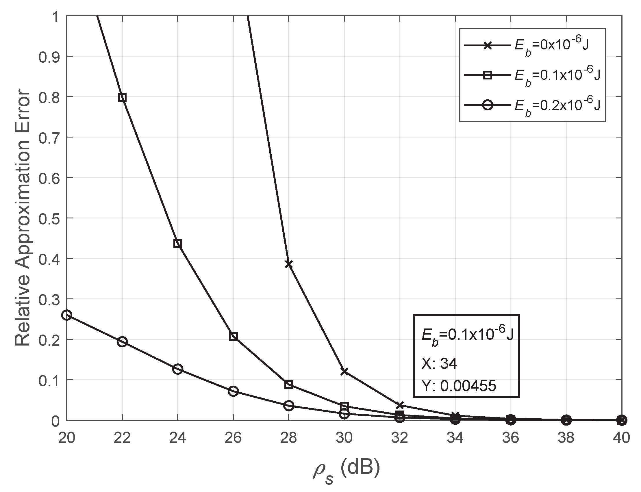
Figure 3 plots the relative approximate error versus with different setting of to illustrate the accuracy of the Taylor series expansion approach. Specifically, according to [22], the relative approximate error can be computed as
where the analytical result is obtained from (14) and the simulation result is achieved by Monte-Carlo simulations. As presented in this figure, the relative approximate error approaches zero with the increase of . For example, when J and dB, the relative approximation error is 0.00455, which provides enough accuracy for the outage capacity. Thus, our derived expressions based on the Taylor series approximation can evaluate the outage performance of the considered network effectively.
Figure 4 shows the relative approximate error versus N with different setting of to verify the accuracy of the Gaussian–Chebyshev approach. Similarly, the analytical result is obtained from (23) and the simulation result is achieved by Monte-Carlos simulations. As shown in this figure, when , the approximate results are sufficiently accurate. Thus, our derived expressions based on the Gaussian–Chebyshev approach can also evaluate the outage/ergodic performance of the investigated network efficiently.
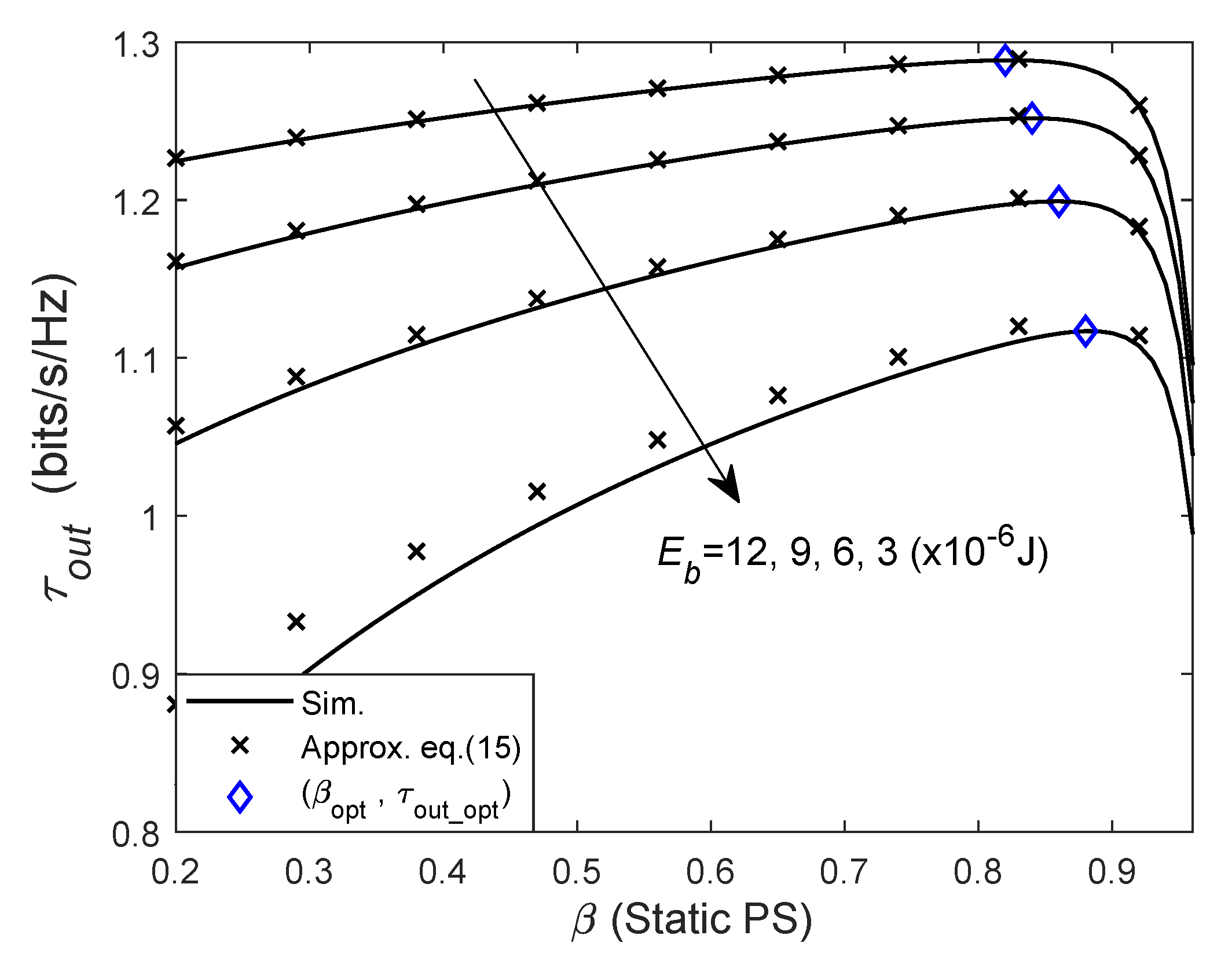
Figure 5 plots the outage capacity against the static PS ratio with the given energy . The approximated results match closely to simulations, which validates the accuracy of derivations in (5). Obviously, the outage capacity is a concave function with respect to , and the optimal static PS ratio can be obtain by one-dimensional search methods. On one hand, we can see that the outage capacity for the fixed increases with the increase of due to the improvement of the transit power at the relay. On the other hand, we can also see that the optimal static PS ratio to maximize the outage capacity decreases as increases due to lower dependence on EH.
Figure 6 shows the variations of the ergodic capacity for the fixed energy with the static PS ratio . From this figure, we can see that the derived approximation results under the expression in (23) match with the simulation results. It is also shown that the ergodic capacity is a concave function of . Likewise, the optimal static PS ratio that maximizes the ergodic capacity can be determined by search techniques. It can be observed that the ergodic capacity for the fixed increases as increases. Moreover, it can also be observed that an increase in causes the optimal static PS ratio to decrease.
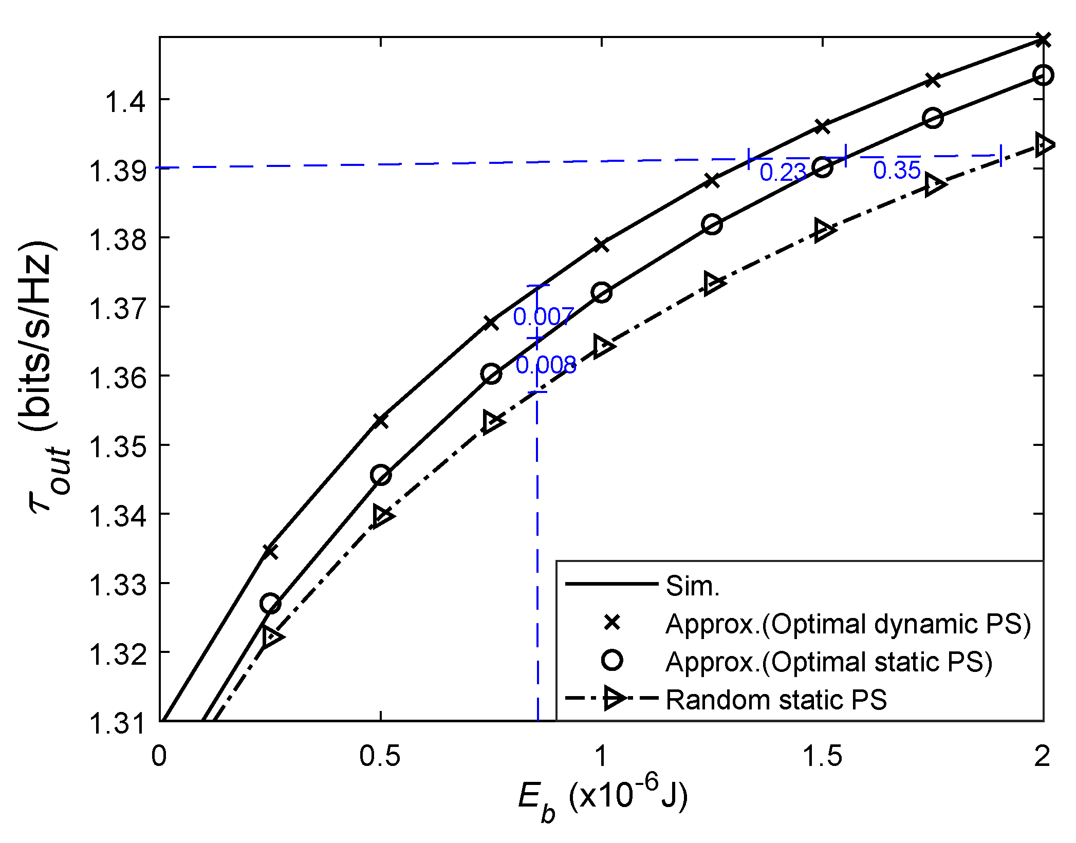
Figure 7 depicts the outage capacity against the assisted energy for three PS schemes. For the random PS scheme, the PS ratio is randomly given from the interval [0,1]. The approximate results match with the simulations results well, which demonstrates the correctness of our derivations. One can see that for a given , the dynamic PS can achieve the highest outage capacity and the performance of random static PS is the worst. This is because the dynamic PS maximizes the overall SNR at each transmission slot by using instantaneous CSI, while the optimal static PS only uses the statistic CSI and no CSI is required for the random scheme. This observation also shows the importance of selecting the appropriated static PS ratio. In addition, it can also be seen that for the same outage capacity, the dynamic PS can consume much less the assisted energy from the battery compared with the optimal static one. The reason is as follows. It can be seen from (25) that the adjustment of the optimal dynamic PS ratio is based on not only the instantaneous CSI but also the assisted energy . This allows to be fully utilized at each time slot.
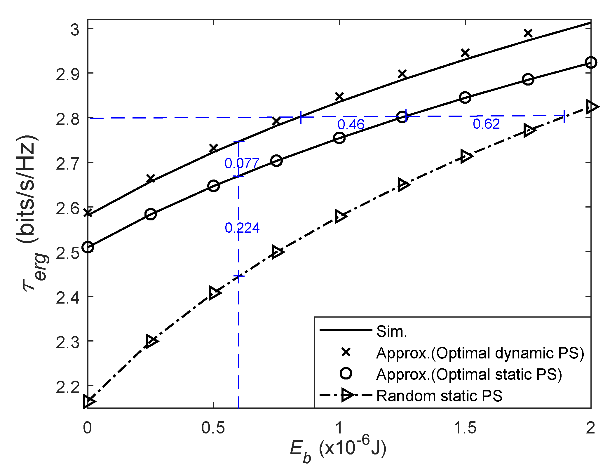
In Figure 8, the ergodic capacity against the assisted energy is investigated. The approximate results match the simulation results well, which verifies the accuracy of the derived ergodic capacity in Section 3.2 or Section 4.2. It can be observed that a higher ergodic capacity can be obtained under the dynamic PS by comparing with results achieved under the random or optimal static PS. The reason is that the dynamic PS ratio is adjusted based on the instantaneous CSI to maximize the overall SNR. Moreover, the random static PS achieves the lowest capacity among three schemes, which also suggests the importance of choosing an appropriated static PS ratio. Besides, it can also be seen that compared with the optimal static PS, a smaller assisted energy consumption is realized by the dynamic PS under the same ergodic capacity.
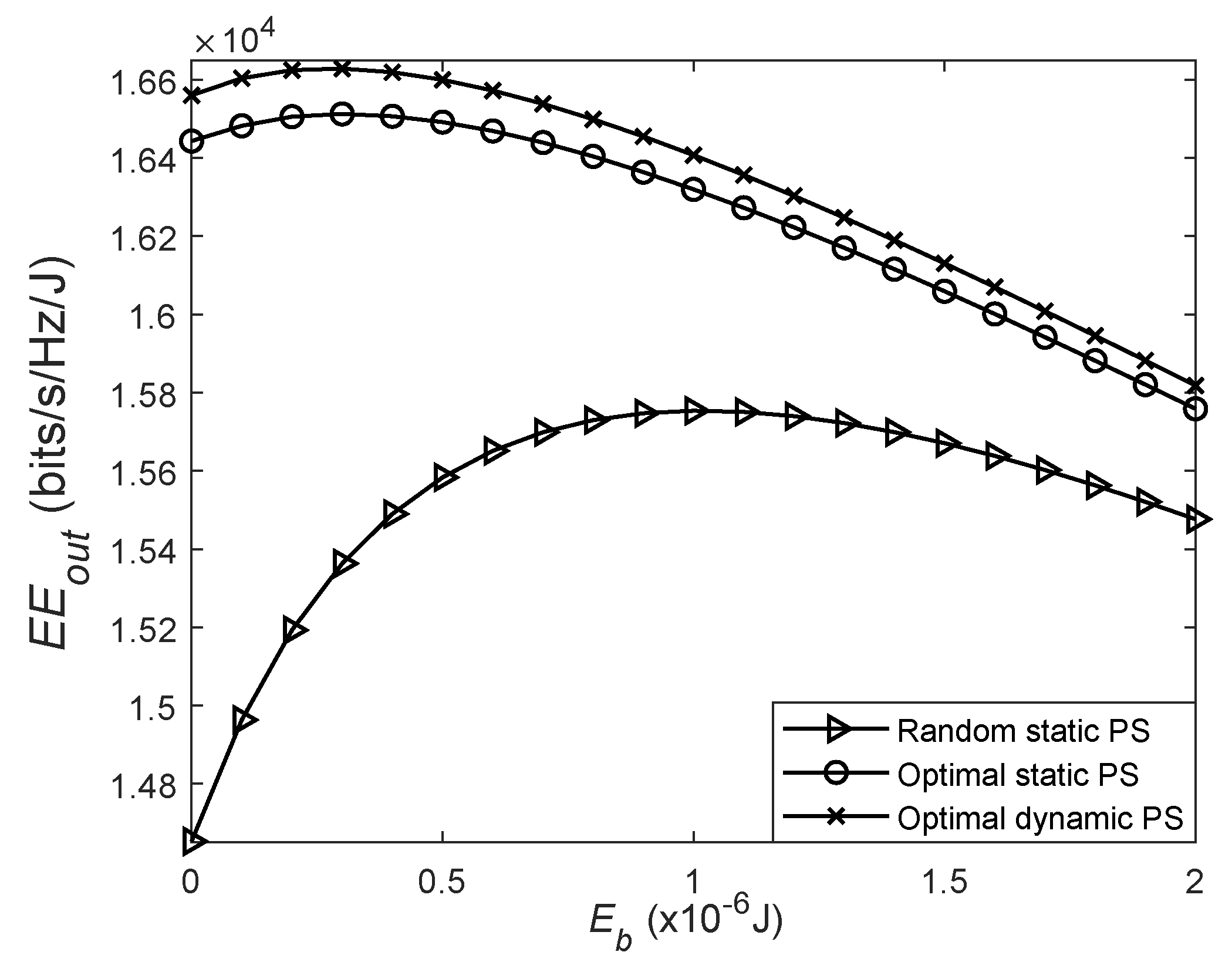
Figure 9 illustrates the energy efficiency versus the assisted energy for three PS schemes. The is defined as , where and denote energy consumptions at the source and the relay, respectively. As can be observed from the figure, the for three PS schemes reaches a peak one after another. After the peak, the is getting lower. This indicates that although increasing increases the outage capacity, the decreases when exceeds a threshold. It can also be observed that the of the dynamic PS is higher than those under the random and optimal static PS. This is due to the fact that the dynamic PS achieves a higher outage capacity compared to the random or optimal static PS under the given total energy consumption.
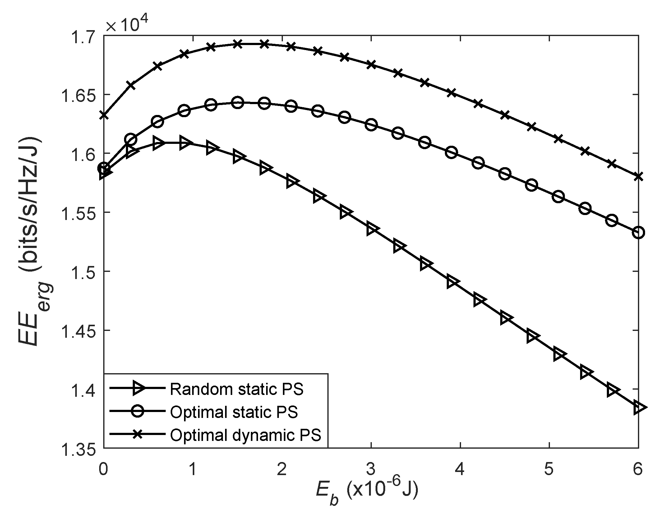
Figure 10 represents the variations of the energy efficiency with the assisted energy , where the is expressed as . We can see that the for three schemes firstly increases and then decreases. This suggests that the selection of appropriate is essential to balance spectral efficiency and energy efficiency. We can also see that the dynamic PS achieves the highest among these three schemes. This is because the dynamic PS achieves a higher ergodic capacity compared to the random or optimal static PS under the given total energy consumption.
6. Conclusions
In this paper, by adopting a static/dynamic PS scheme at the battery-assisted SWIPT DF relay, the expressions for the outage and ergodic capacities were derived. We also compared the performance between the static and dynamic PS schemes. Some findings are summarized as follows. Firstly, the optimal static PS ratio to maximize the outage or ergodic capacity decreases as the assisted energy increases. Secondly, for a given , the dynamic PS can achieve higher outage and ergodic capacities than the random or optimal static PS. Thirdly, compared with the optimal static PS, the dynamic PS consumes much less battery energy while achieving the same outage or ergodic capacity. Fourthly, we provide some insights on the selection of the assisted energy for the static and dynamic PS schemes in terms of energy efficiency.
Finally, we point out two possible future works. Firstly, it is interesting to consider the assumption that the harvested energy at the relay can be used to assist relaying transmission and recharge the battery. In this scenario, we can analyze the outage/ergodic performance in terms of statistical and instantaneous CSI, respectively. Secondly, the system model considered in this paper can be extended to the battery-assisted SWIPT enabled two-way relay system. Note that the system outage probability for the two-way relay system jointly takes the outage evens of both terminals into account, resulting in a high correlation between two links. Hence, quantifying the system outage performance for the two-way relay system is much more challenging than that for the dual-hop relay system.
Author Contributions
Formal analysis, Z.L. and Y.Y.; Funding acquisition, G.L.; Investigation, L.S.; Methodology, Y.Y.; Supervision, G.L.; Writing original draft, Z.L.; Writing review and editing, G.L., L.S. and Y.Y. All authors have read and agreed to the published version of the manuscript.
Funding
This research was funded by the Postgraduate Innovation Fund of Xi’an University of Posts and Telecommunications grant number CXJJLZ2019026.
Conflicts of Interest
The authors declare no conflict of interest.
References
- Li, C.; Yang, H.J.; Sun, F.; Cioffi, J.M.; Yang, L. Multiuser overhearing for cooperative two-way multiantenna relays. IEEE Trans. Veh. Technol. 2016, 65, 3796–3802. [Google Scholar] [CrossRef]
- Li, C.; Zhang, S.; Liu, P.; Sun, F.; Cioffi, J.M.; Yang, L. Overhearing protocol design exploiting intercell interference in cooperative green networks. IEEE Trans. Veh. Technol. 2016, 65, 441–446. [Google Scholar] [CrossRef]
- Liu, K.; Lin, P. Toward self-sustainable cooperative relays: state of the art and the future. IEEE Commun. Mag. 2015, 53, 56–62. [Google Scholar] [CrossRef]
- Jiao, W.; Liu, G.; Wu, H. Queue performance of energy harvesting cognitive radio sensor networks with cooperative spectrum sharing. IEEE Access 2018, 6, 73548–73560. [Google Scholar] [CrossRef]
- Nasir, A.A.; Zhou, X.; Durrani, S.; Kennedy, R.A. Relaying protocols for wireless energy harvesting and information processing. IEEE Trans. Wirel. Commun. 2013, 12, 3622–3636. [Google Scholar] [CrossRef] [Green Version]
- Ghosh, S.; Tamaghna, A.; Maity, S. On outage minimization in rf energy harvesting relay assisted bidirectional communication. Wirel. Netw. 2019, 25, 1. [Google Scholar] [CrossRef]
- Song, K.; Ji, B.; Li, C.; Luxi, Y. Outage analysis for simultaneous wireless information and power transfer in dual-hop relaying networks. Wirel. Netw. 2017, 25, 11. [Google Scholar] [CrossRef]
- Ashraf, M.; Jang, J.W.; Han, J.K.; Lee, K.G. Capacity maximizing adaptive power splitting protocol for cooperative energy harvesting communication systems. IEEE Commun. Lett. 2018, 22, 902–905. [Google Scholar] [CrossRef]
- Sheng, X.; Lu, G.; Shi, L.; Ye, Y. Performance Analysis of Hybrid Protocol Based AF EH Relaying over Asymmetric Fading Channels. Information 2019, 10, 50. [Google Scholar] [CrossRef] [Green Version]
- Gu, Y.; Assa, S. RF-based energy harvesting in decode-and-forward relaying systems: Ergodic and outage capacities. IEEE Trans. Wirel. Commun. 2015, 14, 6425–6434. [Google Scholar] [CrossRef]
- Ye, Y.; Li, Y.; Zhou, F.; Al-Dhahir, N.; Zhang, H. Power splitting-based SWIPT with dual-hop DF relaying in the presence of a direct link. IEEE Syst. J. 2019, 13, 1316–1319. [Google Scholar] [CrossRef]
- Ye, Y.; Shi, L.; Chu, X.; Zhang, H.; Lu, G. On the outage performance of SWIPT-based three-step two-way DF relay networks. IEEE Trans. Veh. Technol. 2019, 68, 3016–3021. [Google Scholar] [CrossRef] [Green Version]
- Do, T.P.; Jeong, Y.; Kim, Y.H. Rate Optimization of Two-Way Relaying with Wireless Information and Power Transfer. Information 2017, 8, 141. [Google Scholar] [CrossRef] [Green Version]
- Li, Z.; Chen, H.H.; Gu, Y.; Li, Y.; Vucetic, B. Accumulate then forward: An opportunistic relaying protocol for wireless-powered cooperative communications. In Proceedings of the 24th European Signal Processing Conference (EUSIPCO), Budapest, Hungary, 29 August–2 September 2016; pp. 813–817. [Google Scholar]
- Pilanawithana, B.; Atapattu, S.; Evans, J. Energy allocation and energy harvesting in wireless relay networks with hybrid protocol. In Proceedings of the 2017 IEEE Global Communications Conference GLOBECOM, Singapore, 4–8 December 2017; pp. 1–6. [Google Scholar]
- Modem, S.; Prakriya, S. Optimization of two-way relaying networks with battery-assisted EH relays. IEEE Trans. Commun. 2018, 66, 4414–4430. [Google Scholar] [CrossRef]
- Modem, S.; Prakriya, S. Performance of EH protocols in two-hop networks with a battery-assisted EH relay. IEEE Trans. Veh. Technol. 2018, 67, 10022–10026. [Google Scholar] [CrossRef]
- Modem, S.; Prakriya, S. Optimization of links with a battery-assisted time-switching wireless energy harvesting relay. IEEE Syst. J. 2018, 12, 3044–3051. [Google Scholar] [CrossRef]
- Agrawal, K.; Prakriya, S. Optimization of time splitting based SWIPT in battery-assisted full duplex relays. In Proceedings of the IEEE 89th Vehicular Technology Conference (VTC2019-Spring), Kuala Lumpur, Malaysia, 28 April–1 May 2019; pp. 1–5. [Google Scholar]
- Gradshteyb, I.S.; Ryzhik, I.M. Table of Integrals, Series, and Products, 7th ed.; Academic: New York, NY, USA, 2007. [Google Scholar]
- Liu, Y.; Ding, Z.; Elkashlan, M.; Poor, H.V. Cooperative non-orthogonal multiple access with simultaneous wireless information and power transfer. IEEE J. Sel. Areas Comm. 2016, 34, 938–953. [Google Scholar] [CrossRef] [Green Version]
- Zhang, C.; Ge, J.; Li, J.; Rui, Y.; Guizani, M. A unified approach for calculating the outage performance of two-way af relaying over fading channels. IEEE Trans. Veh. Technol. 2015, 64, 1218–1229. [Google Scholar] [CrossRef]
Figure 1.
System model of dual-hop relay system.

Figure 2.
Diagram of the PS scheme at battery-assisted simultaneous wireless information and power transfer (SWIPT) enabled relay.
Figure 2.
Diagram of the PS scheme at battery-assisted simultaneous wireless information and power transfer (SWIPT) enabled relay.

Figure 3.
Relative approximate error vs. .

Figure 4.
Relative approximate error vs. N.

Figure 5.
The outage capacity vs. , where dB and bits/s/Hz.

Figure 6.
The ergodic capacity vs. , where dB.

Figure 7.
The outage capacity vs. , where dB and bits/s/Hz.

Figure 8.
The ergodic capacity vs. , where dB.

Figure 9.
Energy efficiency for vs. , where dB and bits/s/Hz.

Figure 10.
Energy efficiency for vs. , where dB.

© 2020 by the authors. Licensee MDPI, Basel, Switzerland. This article is an open access article distributed under the terms and conditions of the Creative Commons Attribution (CC BY) license (http://creativecommons.org/licenses/by/4.0/).
Share and Cite
MDPI and ACS Style
Liu, Z.; Lu, G.; Ye, Y.; Shi, L. On the Performance of Battery-Assisted PS-SWIPT Enabled DF Relaying. Information 2020, 11, 165. https://0-doi-org.brum.beds.ac.uk/10.3390/info11030165
AMA Style
Liu Z, Lu G, Ye Y, Shi L. On the Performance of Battery-Assisted PS-SWIPT Enabled DF Relaying. Information. 2020; 11(3):165. https://0-doi-org.brum.beds.ac.uk/10.3390/info11030165
Chicago/Turabian StyleLiu, Zhipeng, Guangyue Lu, Yinghui Ye, and Liqin Shi. 2020. "On the Performance of Battery-Assisted PS-SWIPT Enabled DF Relaying" Information 11, no. 3: 165. https://0-doi-org.brum.beds.ac.uk/10.3390/info11030165
Note that from the first issue of 2016, this journal uses article numbers instead of page numbers. See further details here.