A Hierarchical Decision-Making Method with a Fuzzy Ant Colony Algorithm for Mission Planning of Multiple UAVs


Department of Network Security and E-Commerce, School of Computer Science, Northwestern Polytechnical University, Xi’an 710072, China
*
Author to whom correspondence should be addressed.
Information 2020, 11(4), 226; https://0-doi-org.brum.beds.ac.uk/10.3390/info11040226
Submission received: 20 February 2020
/
Revised: 6 April 2020
/
Accepted: 15 April 2020
/
Published: 19 April 2020
Abstract
:Unmanned aerial vehicles (UAVs) received an unprecedented surge of people’s interest worldwide in recent years. This paper investigates the specific problem of cooperative mission planning for multiple UAVs on the battlefield from a hierarchical decision-making perspective. From the view of the actual mission planning issue, the two key problems to be solved in UAV collaborative mission planning are mission allocation and route planning. In this paper, both of these problems are taken into account via a hierarchical decision-making model. Firstly, we use a target clustering algorithm to divide the original targets into target subgroups, where each target subgroup contains multiple targets. Secondly, a fuzzy ant colony algorithm is used to calculate the global path between target subgroups for a single-target group. Thirdly, a fuzzy ant colony algorithm is also used to calculate the local path between multiple targets for a single-target subgroup. After three levels of decision-making, the complete path for multiple UAVs can be obtained. In order to improve the efficiency of a collaborative task between different types of UAVs, a cooperative communication strategy is developed, which can reduce the number of UAVs performing tasks. Finally, experimental results demonstrate the effectiveness of the proposed cooperative mission planning and cooperative communication strategy for multiple UAVs.
1. Introduction
1.1. The Multi-Unmanned Aerial Vehicle (UAV) System
The unmanned aerial vehicle is a new type of combat platform with independent flight capability and independent execution capability, which received huge interest and unprecedented attention worldwide [1]. UAVs exhibit outstanding performance and potential applications, including reconnaissance [2], source seeking [3], target detection, and multiple target attack [4,5]. With the rapid development of UAV technology, more and more UAVs will be used in future battlefields. The UAVs receive increasingly large amounts of attention in accomplishing cooperative tasks since their flights can be controlled via a workstation on the ground. So far, a huge amount of research focused on the communication of UAV networks for the cooperative mission planning of UAVs [6]. However, only a few studies demonstrated how to deploy UAVs in specific battlefields for cooperative mission planning. Due to the limitation of current hardware and technical conditions, how to reasonably dispatch UAVs to perform cooperative tasks and choose the best reconnaissance route for a group or cluster of UAVs is of great significance to operations [7,8].
1.2. Collaborative Mission Planning for Multi-UAV
As one of the basic issues of multi-UAV cooperation, collaborative planning of tasks for UAV plays an important role. In a battlefield environment, multi-UAV cooperative mission planning is a very complicated NP problem (non-deterministic polynomial complete problem) because of various constraints [9]. This problem is difficult to solve using a specific algorithm, especially when the scale of the problem is large, and the cost of obtaining the optimal solution is very large, which restricts the application of the actual battlefield [10]. Therefore, a reasonable and effective cooperative strategy for mission planning is very important to improve the operational effectiveness of multi-UAV. Rule-based methods for path planning of multi-UAV cooperation are renowned methods. Reference [11] proposed an improved clustering algorithm to address the collaborative task allocation for multi-UAV systems. In this work, the author proposed an online path planning algorithm to achieve the path planning of multiple UAVs. However, the cooperative allocation of multiple UAVs is an NP problem. With the increase in the number of UAVs, the computational complexity will also increase. Conventional rule-based methods for path planning are often limited by expert experience. Reference [12] developed a time-optimal path planning method and a control strategy to tackle the dilemma of convoy protection for multiple UAVs. The proposed method solves the problem of convoy protection for multiple UAVs in static and dynamic environments. However, the proposed path planning method relies on accurate mathematical modeling methods. Moreover, the expert experience is very important for constructing an effective control model.
In recent years, the latest development of artificial intelligence technology made it possible to achieve more advanced decision-making for the multi-UAV systems. Reinforcement learning is a type of artificial intelligence algorithm that enables the agent to learn an action policy, and it allows a robot to get the maximum expected long-term rewards via a trial-and-error approach. Reinforcement learning was employed to achieve team collaboration for multiple UAVs in an uncertain environment [13]. However, reinforcement learning algorithms are limited to specific tasks, and it is a challenge for the learning experience to be transferred from one task to another. Ant colony optimization (ACO) [14], owing to its unique characteristics and wide applications in tackling tricky combinatorial optimization problems for multi-agent systems [15,16], may be a good solution for the mission planning of multi-UAV to utilize battlefield situations. In fact, ACO simulates the optimization of ant foraging behavior, and a pheromone-guided search mechanism of the ant colony is implemented [17]. However, with the increase in the number of iterations, the traditional pheromone updating method leads to the local drop-dead halt of the ant colony algorithm (AC algorithm). The fuzzy method [18] was used by many researchers and so many works were investigated, including robot soccer games [19], retinal vessel detection [20], and image segmentation [21]. Therefore, a fuzzy method is used to design a more effective pheromone update strategy for the ant colony algorithm. In this paper, fundamentally we use fuzzy logic to design the rule of updating quantities of an ant on the path, and then we use this fuzzy ant colony algorithm to plan the flight path of a UAV, to reach the optimized result.
Recently, an effective collaborative controller for multiple UAVs was a hot issue for applications such as extra-terrestrial exploration and flying missions during disasters [22]. The cooperative mission of multiple UAVs for space exploration is a very meaningful research activity. An effective cooperative mission strategy may be a solution for advanced tasks.
1.3. Research Motivation in this Work
The two key problems to be solved in the UAV collaborative mission planning system are mission allocation and route planning. Motivated by these problems, many scholars carried out studies on cooperative mission planning [22,23,24]. In 2017, many scholars started using the genetic algorithm (GA) to solve the problem of multi-UAV route planning, and related technology based on the coordination mechanism was proposed [25]. In 2016, scholars presented a hierarchical decision-making scheme to perform cooperative missions in an unknown task [26]. In recent years, on the basis of the studies, Reference [27] designed a statistical physical method for the cooperative reconnaissance mission of UAVs, based on the analysis of characteristics about reconnaissance missions. However, these studies showed that most of the research on cooperative mission planning of multiple UAVs focused on route planning, but seldom on mission allocation. Mission allocation refers to the assignment of tasks to UAVs, such as reconnaissance, strike, patrol, and so on. Cooperative mission planning for UAV can also be regarded as an intelligent decision-making problem [28].
Intelligent decision-making helps to solve complex decision-making problems by synthesizing descriptive knowledge about decision-making problems, procedural knowledge in the decision-making process, reasoning knowledge of solving problems, and logical reasoning [29]. How to plan the path of a UAV more effectively is a difficult problem at present. In this paper, for the first time, we combine mission allocation with path planning via a hierarchical decision-making model. Compared with the previous rule-based path planning methods, we propose a fuzzy ant colony algorithm to achieve the path planning of multiple UAVs, which can avoid the solution falling into the local drop-dead halt. An effective communication strategy can achieve the task scheduling of multiple UAVs in the condition of minimum loss.
1.4. Contributions in this Work
In this paper, our main contribution is to present a hierarchical decision-making model for cooperative mission planning of multiple UAVs for a cooperative reconnaissance mission by integrating mission allocation and path planning. Generally, hierarchical analysis of problems is more consistent with human thinking and cognitive behavior [30]. A three-level decision-making method is used to construct the cooperative mission planning model of multiple UAVs. The cooperative mission planning model of a UAV can provide effective decision-making support for reconnaissance of multiple UAVs, which is of great significance for the strategic and technological evolution of a multi-UAV system. The hierarchical decision-making model mainly includes three-layer planning. In the first-level planning, a clustering algorithm is used to cluster the target group, and it clusters the original multiple objects into a new target group, while the original target group is considered as the target subgroup. In the second-level planning, a fuzzy ant colony algorithm is used to plan the global path between target subgroups. In the third-level planning, a fuzzy ant colony algorithm is used again to conduct the local path planning within the target subgroup. In order to improve the communication efficiency between UAVs in the reconnaissance mission, a cooperative communication strategy is designed, which can minimize the number of UAVs needed for communication. Finally, the proposed method is used to solve a common collaborative task planning problem, and the shortest path planning method of the UAV cooperative mission is given, while the shortest distance and flight time are calculated.
1.5. Paper Structure
The remainder of the paper is organized as follows: Section 2 introduces the hierarchical decision-making model and a cooperative mission problem on the battlefield. We also analyze the existing conditions and give a mathematical model with an objective function for this cooperative mission problem. Section 3 presents a fuzzy ant colony algorithm for cooperative mission planning and a clustering method for target clustering. Finally, Section 4 provides the simulation results calculated by the proposed hierarchical decision-making model and introduces the cooperative communication strategy of UAV for communication. Conclusions are drawn in the last section.
2. Problem Statements
2.1. Cooperative Mission Planning for Multiple UAVs
In this paper, a cooperative mission planning problem of multi-UAVs in the battlefield environment is investigated. Previous works usually set multiple waypoints that are needed to be visited by vehicles in the task scene to investigate the cooperative mission method [11,27]. Similar to previous works, we also designed a task scenario with multiple targets. The research work of this paper was inspired by a practical issue. The specific scene configuration was set depending on the practical issue. The description of this problem is as follows: a UAV combat force was equipped with seven UAV bases numbered P01-P07, and each base was equipped with a certain number of FY series UAVs. The coordinates of each base, as well as the type and number of UAVs equipped, are shown in Table 1. The FY-1 UAV was mainly used for target detection, and FY-2 UAV mainly served the task of communication. The speed of FY-1 UAV was 200 km/h. The speed of FY-2 UAV was 300 km/h. The minimum turning radius of UAVs was 70 m.
The FY-1 UAV could be equipped with two sensors, S-1 and S-2. The S-1 sensor was an imaging sensor that used a wide-area search mode to imaging targets. The S-2 sensor was an optical sensor. In order to achieve a certain accuracy of target recognition, the distance between the sensor and the target should not exceed 7.5 km when the ground target is photographed, which can instantly complete the photographic task. Due to the limitations of various technical conditions, this series of UAVs could only be equipped with one of the S-1 and S-2 sensors at a time. Each target should be detected at least once by both UAVs. One UAV was equipped with an S-1 sensor and the other was equipped with an S-2 sensor. In order to ensure effective communication between the UAV and the ground control center, a special FY-2 UAV should be arranged to perform the communication task. The communication distance between the UAV for communication and the UAV for reconnaissance was limited to 50 km. Figure 1 shows the distribution map for the bases of the enemy and our side.
The UAV needs to return to its original base after completing its mission. According to the mission requirements, the reconnaissance target had 10 target groups, named A01–A10. Each target group contained a different number of ground targets. Each target group was equipped with a radar station. In order to complete the cooperative mission of the UAV, we needed to develop the best route and UAV scheduling strategy for the FY-1 UAV to complete the reconnaissance task of 10 target groups, which ensured the minimum total time within the effective detection distance of the radar of the defending side. At the same time, a scheduling method of the UAV was designed for communication to minimize the number of UAVs.
2.2. Hierarchical Decision-Making for Cooperative Mission Planning
In this paper, the cooperative mission planning of multi-UAVs on the battlefield was investigated. After constructing the battlefield model, a mission planning framework for multi-UAVs based on static scene information was developed, as shown in Figure 2. The perceived environmental information was used to construct the environmental model. Environmental understanding is the premise of the decision-making process. The result of decision-making allow the multi-UAVs to produce certain actions. Intelligent algorithms will improve the performance of the decision-making method or improve the efficiency of the decision-making process [31].
In this paper, a hierarchical decision-making model was used to achieve the cooperative task of multi-UAVs. Firstly, the target group was further clustered into three target groups using a clustering method.
In this paper, the original target group was recorded as the target subgroup, and the new target group was recorded as the target group. After clustering, each target was divided into K target groups, and the number of targets in each target group was recorded as . The path planning between each target subgroup can be regarded as a classical TSP (traveling salesman problem) problem [29]. Each target subgroup was simplified as a single particle. In this paper, a fuzzy ant colony algorithm (FACA) was used to tackle the TSP problem. Since the FACA algorithm has different parameters, to improve the efficiency of handling the TSP problem, we needed to empirically tune parameters to make the hyper-parameters more reasonable. After determining the global path of the target subgroup in a single target group, a fuzzy ant colony algorithm was again used to perform a local path planning for the target subgroup; finally, the tracking process of the FY-1 UAV carrying S-1 and S-2 sensors was optimized.
The procedure for the proposed hierarchical decision-making model is shown in Algorithm 1.
| Algorithm 1: Hierarchical decision-making model for the cooperative mission planning |
| Step 1: Each target is divided into several target groups using a clustering algorithm. |
| Step 2: For global path planning, a fuzzy ant colony algorithm is used to calculate the optimal path, which can ensure the minimum total time of each UAV. |
| Step 3: According to the reconnaissance routes of UAVs in each target subgroup, the base of the UAV nearest to each target group can be determined. |
| Step 4: A fuzzy ant colony algorithm is again used to calculate the local path planning within the target subgroup. |
After clustering, each target was divided into target groups, and the number of targets contained in each target group was recorded as . When the UAV had the shortest flight time in the target group, entered the first target with radar detection radius R, and left the target group with radar detection radius R, the detention time of each UAV in the enemy radar detection range was the shortest. The objective function can be expressed as follows:
In Equation (2), is the decision-making variable, which is expressed as follows:
where and indicates that UAV flies from target and target j. represents the time when the UAV flies from target to target . represents the flight speed of the UAV. and indicates that UAVs will not repeat a single target.
In summary, the model of detention time for UAV can be expressed as follows:
In this model, Equation (3) indicates that the UAV has the shortest flight time in the enemy radar detection radius. Equation (4) indicates the time loss when UAV flies from target i to target j, and Equation (5) indicates that every target can be detected. represents the number of target groups.
If the set of the starting points and ending points of the flight path in the target group is the variable denotes whether the UAV “a” starts or ends from the base “p” to the target group.
The objective function and the shortest flight time of UAV can be expressed as follows:
Equation (7) indicates whether the UAV a is flying from base p to target i. If , UAV flies from base p to target i. The time loss of UAV which flies from the base to the starting point or ending point of the target group is denoted by Equation (8). is the number of UAVs in base p. Equation (9) shows that the number of UAVs on the mission at each base does not exceed the number of UAVs owned by the base. is the maximum endurance of the UAV. Equation (10) indicates that the flight time of each UAV cannot exceed its longest flight time. The shortest flight time outside the radar detection range is . Equation (11) denotes the total flight time of the UAV.
3. Cooperative Path Planning Based on Fuzzy Ant Colony Algorithm
3.1. Target Clustering
To address the clustering problem of multi-targets, inspired by the hierarchical clustering method [32], this paper proposes a clustering method with the shortest distance, which can divide the targets into several target groups. In practice, we usually set a fixed number of iterations to get a certain number of classes, which are usually based on a specific situation. The proposed method is based on the shortest distance between classes. There are N targets, and represents the distance between the target and the j target. At the beginning of the clustering, each target is regarded as a class. is used to represent the initial class. The distance between a class and class is represented by . The rules are set as shown in Equation (12).
3.2. Fuzzy Ant Colony Algorithm (FACA)
If we can plan the local path and the global path using a hierarchical decision-making method, we can minimize the flight time of the UAV. The path planning of the UAV among target subgroups in a target group is a TSP problem, which is solved using a fuzzy ant colony algorithm. The ant colony algorithm imitates ants’ life behavior [33]. When ants are walking, they leave pheromones on the route. Pheromones are chemicals that decrease over time. When other ants smell the pheromone, they move in the direction of the presence of the pheromone. Similarly, other ants leave pheromones in their path. A larger amount of pheromone makes it more likely that a pathway will be selected. Surely, in each stage, the probability of choosing the shortest path is increased and, eventually, most of the ants move onto the shortest path. The ant colony algorithm guides ants to choose the best path by adjusting the amount of pheromone in each path. The traditional ant colony algorithm is easy to fall into a local drop-dead halt; thus, we introduce fuzzy logic to improve the ant colony algorithm in the pheromone update rules.
The procedure of the path planning method based on a fuzzy ant colony algorithm for multi-UAVs is described below.
We assume that is the intensity of the exohormone on the edge at moment according to a probability function that takes the distance of the target subgroups and the number of pheromones on the edge of the target subgroups as the variables. The number of ants is m. Each ant can start from its starting position and return to its starting position. Unless the round trip is completed, the ant is not allowed to move to the visited target subgroup, and the walking of ants is controlled by the tabu list. If represents the tabu list of the ant, represents element in the tabu list. After completing a round trip, ants release pheromones on every edge of their visit.
At the initial time, the information on each path is equal, and ( is constant). The ant determines the direction of movement according to the information of each route. indicates the probability that the ant moves from position to position at time. The rule for is as follows:
In Equation (13), represents the next target subgroup that allows ant to choose. Unlike the actual ant colony, the artificial ant colony system has a memory function. is used to record the target subgroup that ants are currently traversing, and tabuk is dynamically adjusted with evolution. indicates the visibility of edge , which generally takes and to represent the distance between the target subgroup and the target subgroup . denotes the relative importance of the trajectory, and denotes the relative importance of visibility. denotes the persistence of the trajectory, and denotes the attenuation of the trajectory.
Over time, the information left in the past gradually disappears. The parameter is used to indicate the degree of information disappearance. After times, the ant completes a cycle. The amount of information on each path should be adjusted according to Equation (14).
where denotes the amount of information left in the path by the ant in this cycle. represents the increment of information on path on this cycle. represents the path length of the ant traveling around.
In this paper, fuzzy logic is added to the ant colony algorithm. The traveling counter and the quality value of the solution obtained by each ant are used as the fuzzy input of the fuzzy controller. Firstly, the two quantities are fuzzified; then, the fuzzy control rules of information updating are determined. Finally, the output fuzzy quantities are de-fuzzified, and the updating quantities of each ant on the path are obtained. The fuzzy control rule is a key component of the fuzzy controller, which determines the performance of the fuzzy controller. Generally, the setting of fuzzy rules needs to consider the fuzzy input domain and the output domain. The setting of fuzzy rules usually depends on expert experience or domain knowledge; thus, it is an empirical rule. Therefore, to address the issue investigated, we develop a fuzzy rule according to the experience of experts to improve the performance of the ant colony algorithm.
Firstly, the input values are fuzzed. The setting of input and input fields is . We use Equation (15) to map the domain to the domain .
For input 1 and input 2 we convert the input to and using Equation (15).
This paper sets fuzzy control rules as shown in Table 2.
In this paper, the number of fuzzy parameters is set to five, and the fuzzy input and output spaces are divided into five fuzzy sets. S stands for “small”, M-stands for “smaller”, M represents “middle”, M + represents “higher”, and B represents “high”. The corresponding relationship between the fuzzy value and the actual value is shown in Table 3.
This paper sets the fuzzy rule to IF x is and y is , then z is . Therefore, for the fuzzy output , the final output is .
The procedure for the fuzzy ant colony algorithm is shown in Algorithm 2.
| Algorithm 2: Fuzzy ant colony algorithm |
| Step 1: ( is the number of iterations or searches), and are initialized separately, and ants are placed on target subgroups. |
| Step 2: The initial starting point of each ant is placed in the current solution set. For each ant, which is moved to the next target subgroup according to probability , the target subgroup is placed in the current solution set. |
| Step 3: Calculate the length of the path of each ant and record the best solution. |
| Step 4: The strength of the trajectory is updated according to the renewal equation. |
| Step 5: . |
| Step 6: If is less than the expected number of iterations and does not degenerate (that is, the same solution is found), go back to Step 2. |
| Step 7: Output the best solution at present. |
3.3. Path Planning Based on a Fuzzy Ant Colony Algorithm
Global path planning is conducted using a fuzzy ant colony algorithm. After the global path planning of the UAVs, local path planning is conducted, and the local path planning plans the flight path in the single target subgroup. Given multiple targets, a path is obtained that makes one UAV traverse all targets and return to the starting point, and each target is only detected once by the UAV. The fuzzy ant colony algorithm is applied to compute the shortest path within a target group. The path of the UAV in the target group is an undirected path with one entry and one exit. Therefore, the direction of entry needs to be chosen according to the location of the last target group, thereby further shortening the length of the flight path.
The strategy for determining entry and exit is shown in Algorithm 3.
| Algorithm 3: The strategy for determining entry and exit in the target group |
| Step 1: The flight routes of each target group are planned separately, and the entries are determined. |
| Step 2: The distance of centroid is calculated between two adjacent target groups in the route obtained by the local path planning. |
| Step 3: The first target in each target group is the entry of the target group. |
| Step 4: The exit of each target group is consistent with the entry of the target group. |
After the calculation, the flight routes of the UAV in each target group can be obtained, and then the starting point and the ending point of each route can be found. Then, according to the distance from the starting point and the ending point of each route to each base, the mission of the UAV can be allocated, and the optimal scheduling strategy can be worked out.
3.4. Path Optimization of the UAV with S-1 Sensor
Figure 3 shows the optimal detection route of a target subgroup for the UAV with an S-1 sensor. The rules of the trajectory of UAVs with S-1 sensors are set as follows:
- The starting point and ending point of UAV are both bases.
- The S-1 sensor is installed on the right side of the UAV.
- The route between the two targets is , and the UAV leaves the target and flies to the next target .
- The starting point I of the route is the end point of the route , and the ending point is the tangent point of the circle with the target as the center.
In Figure 3, the black dotted line represents the shortest path within the target group obtained by local path planning, and the red line represents the path of the UAV arranged according to sensor constraints. After taking off from the base, the UAV will fly to the tangent point of the circle where the target a is located.
After the reconnaissance of the target a is completed, the UAV flies to target b and directly reaches the tangent point of the circle where target b is located; this is repeated until it returns to the base after the reconnaissance. The distribution of the target is scattered. When the route is shifted to the left, the mileage of the path is less than the shortest path, and when the route is shifted to the right, the mileage of the path is greater than the shortest path. In the real reconnaissance of UAV, the trajectory of the UAV can be smaller than the optimal trajectory unless the distribution of targets is close to the circle and the optimal trajectory is in the counterclockwise direction. Considering that the distribution of enemy targets on the battlefield has no obvious law, it can be considered that the optimal route obtained by the planning has the same probability of deviating left and right in the direction of flight. However, the mileage of UAV is likely to be greater than the shortest route that is obtained when flying directly over the target. Under the condition of satisfying the imaging conditions of sensors, the path planning approaches the optimal path planning method to the greatest extent.
3.5. Path Optimization of the UAV Equipped with S-2 Sensor
The S-2 sensor is different from the S-1 sensor. Figure 4 shows the optimal detection route of a target subgroup for the UAV with the S-2 sensor. The reconnaissance can be completed only if the distance between the UAV and the target does not exceed the maximum observation distance. Therefore, the shortest route obtained in the decision of the second layer can be further optimized.
The rules of UAV track with S2 sensors are set as follows:
- The starting point and the end point of UAV are both bases.
- The S-2 sensor can shoot any target in an instant.
- The route between the two target points is , and the UAV leaves the target and flies to the next target point .
The starting point of the route is the end point of the route , and the end point of the UAV track is the intersection of the UAV path and the circle formed by .
The black dotted line in Figure 4 is the shortest route in the target group obtained by the decision of the second layer, and the red line is the UAV track arranged according to the characteristics of the sensor. When the UAV takes off from the base and flies to the target, it directly reaches the intersection with the circle where the target a is located. After the target a is detected, it flies to the target b and directly reaches the intersection of the circle where the target b is located, and finally returns to the base. The first and second line segment in the red path is the UAV’s mileage to target a and target b, respectively, according to the shortest line in the decision of the second level, and the line segment c is the UAV’s mileage to target b after detecting target a. Since the takeoff route from the base is certain, according to the principle that the sum of the length of the two sides of the triangle is longer than the length of the third side, the red route is inevitably superior to the black route. Due to the characteristics of the S-2 sensor, in a route, if the next target point contains the current starting point, the UAV can directly detect the next target point, and the UAV skips the next target point and flies to the target point afterward.
4. Experiment and Analysis
4.1. Results of Target Clustering
The proposed target clustering method was used to get the target clustering results. The clustering results are shown in Figure 5 and Table 4. We can get three different target groups: A, B, and C. The red line represents the target group A. The green line represents the target group B. The yellow line represents the target group C.
In this paper, a clustering method was used to get three different target groups: A, B, and C. After clustering, the base of UAV flying to each target group was obtained using the nearest principle. The target group A was sent to UAV by base P01 for reconnaissance. The target group B was sent to UAV by base P01 for reconnaissance. The target C was sent to UAV by base P06 for reconnaissance. UAVs with S-1 sensors and UAVs with S-2 sensors were needed to detect each target according to conditions. In order to minimize the flight path of UAV, the flight path of UAV with the S-1 sensor was the same as that of UAV with the S-2 sensor.
4.2. Experiment for Path Planning of Multiple UAVs
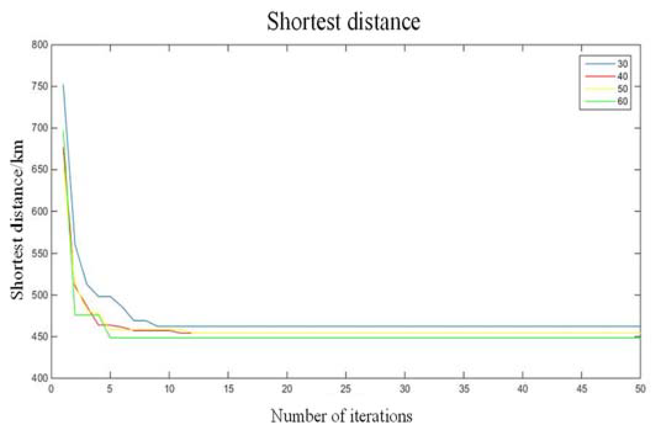
Because the hyper-parameters are critical for the ant colony algorithm, we must firstly choose the best parameter configuration. In the Matlab simulator, this paper conducted an experiment to adjust the parameters of the fuzzy ant colony algorithm in solving the specific problem, taking the TSP problem as an example. The number of an ant colony is an important factor that affects the convergence rate and performance of the ant colony algorithm. The shortest distance and average distance were compared when the number of ants was 30, 40, 50, and 60. The number of iterations was set to 50 times, and the number of targets was 50. For each parameter configuration, we randomly generated the targets to test this algorithm parameter using a considerable number of tests. In each test, four parameter configurations were compared. For one test, the experimental results are shown in Figure 6 when the number of ant colonies was 30. The comparison of the shortest path and the average path of a different number of ant colonies is shown in Figure 7 and Figure 8.
When the number of ant colonies was 30, the best shortest path could be obtained, but the average distance was relatively large when the number of ants was 30. Considering that the shortest path is more important in UAV path planning, the final parameters were as follows: number of populations = 30; number of iterations = 60. Then, we transferred the fuzzy ant colony algorithm with this configuration to a more complex task. In this task, there were 500 targets on the map.
In Figure 9, the experimental results show that the number of iterations was 14,979, and the total distance was 218.9269 if there were 500 targets. Using the fuzzy ant colony algorithm with this configuration, the total length of the path would eventually converge in a more complex task. The distribution matrix represents the result of path planning, which shows the distance between different targets. In the distribution matrix, different colors represent different distances between targets. Blue means closer, while red means farther. In this paper, the parameters were used in the fuzzy ant colony algorithm for path planning of the UAV, and the global path planning of the three target groups was obtained as shown in Figure 10. In Figure 10, flight paths for the three target groups of UAVs were computed using the fuzzy ant colony algorithm.
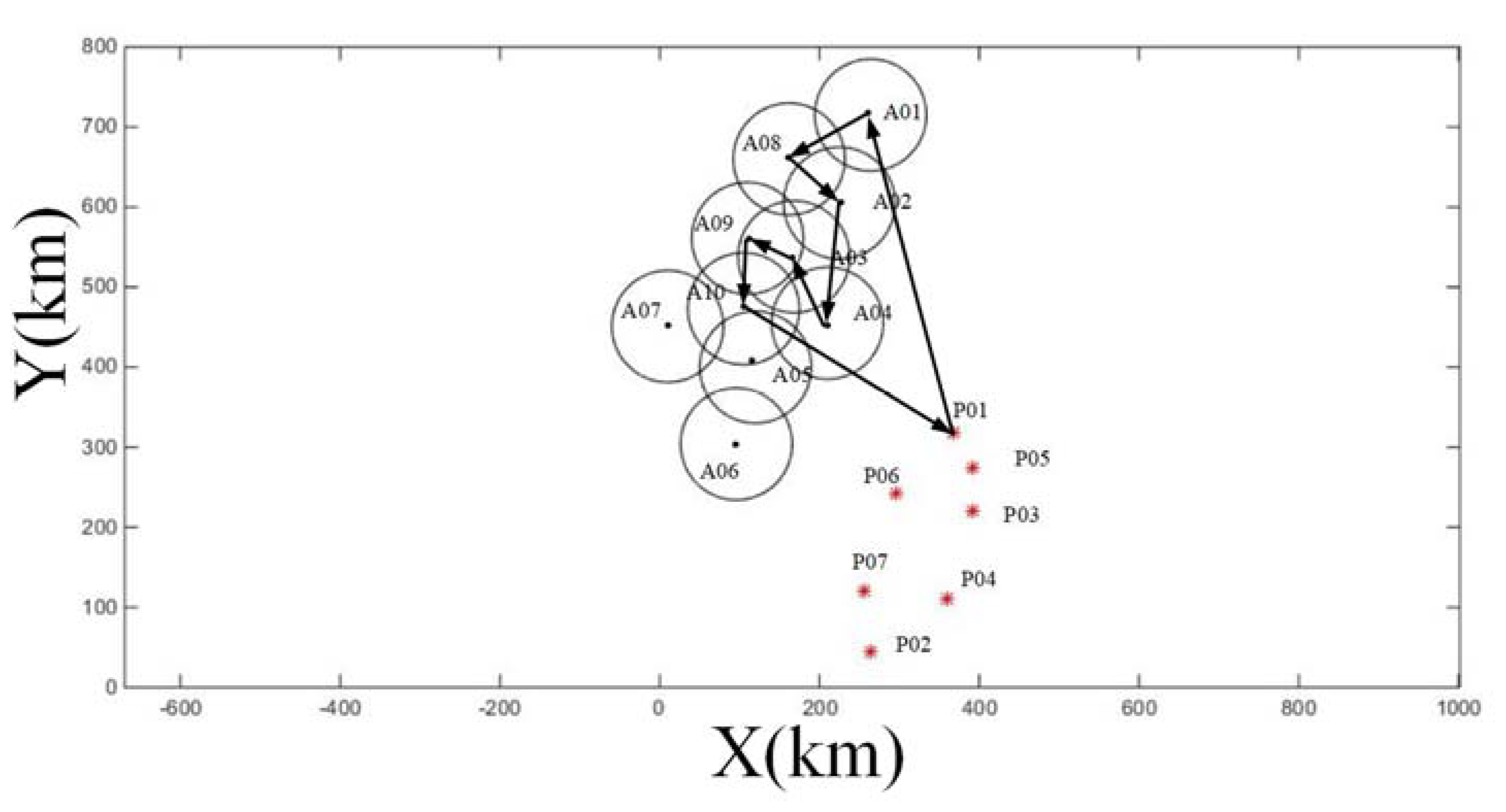
The results of local path planning for multi-UAVs are shown in Figure 11. This paper took the path planning of UAV in the C target group as an example. In Figure 11, the direction of the flight of UAV is indicated by arrows. Since the path of the UAV with the S-1 sensor was the same as that of the UAV with the S-2 sensor, the flight path of the UAV with the S-2 sensor could be obtained after the path of UAV with the S-1 sensor was obtained. Fuzzy logic was added to the ant colony algorithm to change the updating quantities of each ant on the path. The global and local flight paths planned by the proposed fuzzy ant colony algorithm could ensure the shortest flight path of the multi-UAVs.
In this paper, the path planning of the FY-1 UAV with the same sensor was conducted, and the path planning of the FY-1 UAV with different sensors was not needed. To save fuel, multi-UAVs which have different sensors and the same flight path take off from the same base. Base P01 arranged two UAVs to detect target group A and target group B. The two UAVs carried the S-1 sensor and the S-2 sensor for detection. Base P06 arranged a UAV with an S-1 sensor and a UAV with an S-2 sensor to detect target group C.
The shortest flight path of multi-UAVs was calculated using the proposed hierarchical decision-making model, and the results are shown in Table 5. The flight distance and flight time were the same because multi-UAVs equipped with different sensors had the same route.
It can be calculated from Table 5 that the flight distance of the 1-1 UAV was 2202.32 km, and the flight distance of the 1-2 UAV was 1830.1 km, while the flight distance of the 6-1 UAV was 1731.84 km. Therefore, in order to complete the entire flight mission, the total flight distance of the UAV was 5764.26 km, the detention time was 16.1795 h, and the flight time was 28.8213 h, for a total of 970.77 min.
4.3. Cooperative Communication Strategy of Multi-UAVs
While the FY-1 UAV is performing reconnaissance missions, the information obtained by the FY-1 UAV must be transmitted back to the ground workstation by the FY-2 UAV. The communication distance between the UAV for communication and the UAV performing the detecting mission was limited to 50 km, and the UAV for communication could keep up communication with the ground control center at any time under the normal working circumstance. Therefore, in order to complete the cooperative communication between the UAVs, it was only necessary to ensure that the distance between the FY-2 UAV and the UAV performing the detecting mission was within 50 km. The UAV for communication needed to follow the UAV performing tasks in real time. Therefore, the flight path of the UAV for communication was consistent with that of the UAV performing tasks. When the flight time exceeded the endurance time, the FY-2 UAV performing the communication task was scheduled to return, and the new FY-2 UAV took off. The endurance time was 8 h. The UAV continued to complete the communication task.
The conclusion from the previous section shows that two UAVs took off from the P01 base and one UAV took off from the P06 base, while the flight routes of the three UAVs were all different. Since the flight paths of the three UAVs were different, it was impossible to use one FY-2 UAV for detection. Then, we considered using two FY-2 UAVs for communication. The cooperative communication strategy was as follows: the FY-2 UAV taking off from the P06 base detected target group A and target group B. Firstly, the FY-2 UAV communicated with 1-1 UAV. After passing through the target group A, the 1-1 UAV returned, and the FY-2 UAV continued to communicate with the 1-2 UAV. Another FY-2 UAV communicated with the 6-1 UAV taking off from the P06 base. The flight path of the two FY-2 UAVs is shown in Figure 12 and Figure 13.
Table 6 shows the results of cooperative communication of UAVs for communication, which were numbered No1 and No2. It can be seen from the calculation results obtained in Table 6 that the flight time of the two UAVs was less than the maximum endurance time, which satisfied the conditions. Therefore, the proposed cooperative communication method is feasible. In summary, in order to complete the detection mission of the UAV, at least two UAVs for communication need to be arranged.
5. Conclusions
In this paper, we investigated the specific problem of cooperative mission planning for multiple UAVs on the battlefield, from a hierarchical decision-making perspective. The specific problem was modeled as a mathematical model for hierarchical decision-making, considering the existing resources and constraints. Moreover, we also considered two key issues of mission allocation and route planning in cooperative mission planning and developed a hierarchical decision-making model to address them. In order to plan the flight path for UAVs, we also proposed a fuzzy ant colony algorithm to design the rule of updating quantities of an ant on the path. The proposed method can be described as follows: firstly, the target group was clustered according to the distance by a clustering method. After clustering, the original multiple target groups were clustered into a large target group. Then, a fuzzy ant colony algorithm was used to perform global path planning between target subgroups. Finally, the fuzzy ant colony algorithm was again used for path planning within a single target subgroup. The simulation results were calculated using the proposed method. In order to make communication between UAVs more effective, a cooperative communication strategy was developed. The detection route of UAVs for communication could be planned, and the number of UAVs for communication needed was minimized via the cooperative communication strategy.
However, a few issues still need to be investigated. For instance, each target group may dynamically change the location and number of targets. Furthermore, UAVs may encounter obstacles during flight. Therefore, obstacle avoidance is very necessary for effective flight. Some of the research topics are mentioned below as the future scope for research in UAV mission planning with a fuzzy intelligent algorithm. In a specific battlefield environment, the existence of some obstacles is inevitable. An accurate obstacle avoidance algorithm is a prerequisite for effective flight, and the reinforcement learning algorithm may provide a good solution [34,35,36]. We will investigate cooperative mission planning in-flight scenarios with obstacles. In some complex scenarios, such as extra-terrestrial exploration, the location or number of targets may change. In dynamic scenarios, UAVs may detect new targets in a path planning process. An emergency measure using a machine learning method is needed when the UAV detects a new target. Therefore, cooperative mission planning for multiple UAVs in dynamic target scenarios will be studied in the future.
Author Contributions
Methodology, L.Z.; resources, L.Z.; software, L.Z. and X.S.; supervision, Y.Z.; writing—original draft, L.Z. All authors have read and agreed to the published version of the manuscript.
Funding
This work was supported by the Civil Aircraft Project under Grant No. XJ-2015-D-76, the major and key project of the Shaanxi Province key research and development plan under Grant No. 2016MSZD-G-8-1, and the ZFPR Foundation of China under Grant No. 31511070301.
Conflicts of Interest
The authors declare no conflicts of interest.
References
- Mozaffari, M.; Saad, W.; Bennis, M.; Debbah, M. Unmanned aerial vehicle with underlaid device-to-device communications: Performance and tradeoffs. IEEE Trans. Wirel. Commun. 2016, 15, 3949–3963. [Google Scholar] [CrossRef]
- Roldán, J.J.; Cerro, J.D.; Barrientos, A. Using Process Mining to Model Multi-UAV Missions through the Experience. IEEE Intell. Syst. 2017, 32, 40–47. [Google Scholar] [CrossRef]
- Han, J.; Chen, Y.Q. Multiple UAV Formations for Cooperative Source Seeking and Contour Mapping of a Radiative Signal Field. J. Intell. Robot. Syst. 2014, 74, 323–332. [Google Scholar] [CrossRef]
- Freitas, S.; Silva, H.; Almeida, J.; Silva, E. Hyperspectral imaging for real-time unmanned aerial vehicle maritime target detection. J. Intell. Robot. Syst. 2018, 90, 551–570. [Google Scholar] [CrossRef] [Green Version]
- Farmani, N.; Sun, L.; Pack, D.J. A scalable multitarget tracking system for cooperative unmanned aerial vehicles. IEEE Trans. Aerosp. Electron. Syst. 2017, 53, 1947–1961. [Google Scholar] [CrossRef]
- Chen, J.; Wu, Q.; Xu, Y.; Zhang, Y.; Yang, Y. Distributed Demand-aware Channel-slot Selection for Multi-UAV Networks: A Game-theoretic Learning Approach. IEEE Access 2018, 6, 14799–14811. [Google Scholar] [CrossRef]
- Liu, Y.; Luo, Z.; Liu, Z.; Shi, J.; Cheng, G. Cooperative Routing Problem for Ground Vehicle and Unmanned Aerial Vehicle: The Application on Intelligence, Surveillance, and Reconnaissance Missions. IEEE Access 2019, 7, 63504–63518. [Google Scholar] [CrossRef]
- Shi, H.; Li, X.; Hwang, K.-S.; Pan, W.; Xu, G. Decoupled Visual Servoing with FuzzyQ-Learning. IEEE Trans. Ind. Inform. 2018, 14, 241–252. [Google Scholar] [CrossRef]
- Sahingoz, O.K. Generation of Bezier Curve-Based Flyable Trajectories for Multi-UAV Systems with Parallel Genetic Algorithm. J. Intell. Robot. Syst. 2014, 74, 499–511. [Google Scholar] [CrossRef]
- Guan, X.; Zhang, X.; Wei, J.; Hwang, I.; Zhu, Y.; Cai, K. A strategic conflict avoidance approach based on cooperative coevolutionary with the dynamic grouping strategy. Int. J. Syst. Sci. 2016, 47, 1995–2008. [Google Scholar] [CrossRef]
- Fu, Z.; Mao, Y.; He, D.; Yu, J.; Xie, G. Secure multi-uav collaborative task allocation. IEEE Access 2019, 7, 35579–35587. [Google Scholar] [CrossRef]
- Oliveira, T.; Aguiar, A.P.; Encarnação, P. A convoy protection strategy using the moving path following method. In Proceedings of the 2016 International Conference on Unmanned Aircraft Systems (ICUAS), Arlington, VA, USA, 7–10 June 2016; pp. 521–530. [Google Scholar]
- Hung, S.M.; Givigi, S.N.; Noureldin, A. A Dyna-Q (Lambda) Approach to Flocking with Fixed-Wing UAVs in a Stochastic Environment. In Proceedings of the 2015 IEEE International Conference on Systems, Man, and Cybernetics (SMC), Kowloon, China, 9–12 October 2015. [Google Scholar]
- Liao, T.; Socha, K.; de Oca, M.A.M.; Stützle, T.; Dorigo, M. Ant Colony Optimization for Mixed-Variable Optimization Problems. IEEE Trans. Evol. Comput. 2014, 18, 503–518. [Google Scholar] [CrossRef]
- Yang, Q.; Chen, W.-N.; Yu, Z.; Gu, T.; Li, Y.; Zhang, H.; Zhang, J. Adaptive multimodal continuous ant colony optimization. IEEE Trans. Evol. Comput. 2016, 21, 191–205. [Google Scholar] [CrossRef] [Green Version]
- Shi, H.; Lin, Z.; Zhang, S.; Li, X.; Hwang, K.-S. An adaptive Decision-making Method with Fuzzy Bayesian Reinforcement Learning for Robot Soccer. Inf. Sci. 2018, 436–437, 268–281. [Google Scholar] [CrossRef]
- Shelokar, P.; Siarry, P.; Jayaraman, V.; Kulkarni, B. Particle swarm and ant colony algorithms hybridized for improved continuous optimization. Appl. Math. Comput. 2007, 188, 129–142. [Google Scholar] [CrossRef]
- Juang, C.-F.; Lu, C.-M.; Lo, C.; Wang, C.-Y. Ant Colony Optimization Algorithm for Fuzzy Controller Design and Its FPGA Implementation. IEEE Trans. Ind. Electron. 2008, 55, 1453–1462. [Google Scholar] [CrossRef]
- Olivas, F.; Valdez, F.; Castillo, O.; Gonzalez, C.I.; Martinez, G.; Melin, P. Ant colony optimization with dynamic parameter adaptation based on interval type-2 fuzzy logic systems. Appl. Soft Comput. 2017, 53, 74–87. [Google Scholar] [CrossRef]
- Varma, P.R.K.; Kumari, V.V.; Kumar, S.S. Feature selection using relative fuzzy entropy and ant colony optimization applied to real-time intrusion detection system. Procedia Comput. Sci. 2016, 85, 503–510. [Google Scholar] [CrossRef] [Green Version]
- Raghtate, G.S.; Salankar, S.S. Modified Fuzzy C Means with Optimized Ant Colony Algorithm for Image Segmentation. In Proceedings of the International Conference on Computational Intelligence & Communication Networks, New Tehri, India, 23–25 December 2016. [Google Scholar]
- Nigam, N.; Bieniawski, S.; Kroo, I.; Vian, J. Control of Multiple UAVs for Persistent Surveillance: Algorithm and Flight Test Results. IEEE Trans. Control Syst. Technol. 2012, 20, 1236–1251. [Google Scholar] [CrossRef]
- Dao-Jing, D.; Yun-Hong, M.A.; Jie, G. Cooperative Mission Planning of Multiple UAVs Based on Parallel GAPSO Algorithm. Electron. Opt. Control 2016, 11, 18–22. [Google Scholar]
- Wilhelm, J.; Rojas, J.; Eberhart, G.; Perhinschi, M. Heterogeneous aerial platform adaptive mission planning using genetic algorithms. Unmanned Syst. 2017, 5, 19–30. [Google Scholar] [CrossRef]
- Ramirez-Atencia, C.; Bello-Orgaz, G.; R-Moreno, M.D.; Camacho, D. Solving complex multi-UAV mission planning problems using multi-objective genetic algorithms. Soft Comput. 2017, 21, 4883–4900. [Google Scholar] [CrossRef]
- Yao, W.; Wan, N.; Qi, N. Hierarchical path generation for distributed mission planning of UAVs. In Proceedings of the 2016 IEEE 55th Conference on Decision and Control (CDC), Las Vegas, NV, USA, 12–14 December 2016; pp. 1681–1686. [Google Scholar]
- Shi, Z.; Huang, X.; Hua, Y.; Xu, D. Statistical physics method for multi-base multi-UAV cooperative reconnaissance mission planning. In Proceedings of the 2015 IEEE Advanced Information Technology, Electronic and Automation Control Conference (IAEAC), Chongqing, China, 19–20 December 2015; pp. 64–68. [Google Scholar]
- Capitan, J.; Merino, L.; Ollero, A. Cooperative decision-making under uncertainties for multi-target surveillance with multiples UAVs. J. Intell. Robot. Syst. 2016, 84, 371–386. [Google Scholar] [CrossRef]
- Yang, W.L. Optimization and improvement for multi-UAV cooperative reconnaissance mission planning problem. In Proceedings of the 11th International Computer Conference on Wavelet Actiev Media Technology and Information Processing (ICCWAMTIP), Chengdu, China, 19–21 December 2014. [Google Scholar]
- Ren, T.Z.; Zhou, R.; Hao, L.I. An Emotional Intelligence Based Autonomous Decision-Making Method for UAVs. Electron. Opt. Control 2017, 3, 11–15. [Google Scholar]
- Guo, Z.X.; Wong, W.K.; Min, L. A multivariate intelligent decision-making model for retail sales forecasting. Decis. Support Syst. 2013, 55, 247–255. [Google Scholar] [CrossRef]
- Pusadan, M.Y.; Buliali, J.L.; Ginardi, R.V.H. Anomaly detection of flight routes through optimal waypoint. J. Phys. Conf. Ser. 2017, 801, 12041. [Google Scholar] [CrossRef]
- Saidi-Mehrabad, M.; Dehnavi-Arani, S.; Evazabadian, F.; Mahmoodian, V.; Mahmoodiana, V. An Ant Colony Algorithm (ACA) for solving the new integrated model of job shop scheduling and conflict-free routing of AGVs. Comput. Ind. Eng. 2015, 86, 2–13. [Google Scholar] [CrossRef]
- Shi, H.; Xu, M. A Multiple Attribute Decision-Making Approach to Reinforcement Learning. IEEE Trans. Cogn. Dev. Syst. 2019. [Google Scholar] [CrossRef]
- Hu, C.; Xu, M. Adaptive Exploration Strategy with Multi-Attribute Decision-Making for Reinforcement Learning. IEEE Access 2020, 8, 32353–32364. [Google Scholar] [CrossRef]
- Shi, H.; Xu, M.; Hwang, K.-S. A Fuzzy Adaptive Approach to Decoupled Visual Servoing for a Wheeled Mobile Robot. IEEE Trans. Fuzzy Syst. 2019. [Google Scholar] [CrossRef]
Figure 1.
Distribution map for the bases of the enemy and our side.

Figure 2.
The framework for the mission planning of multi-UAVs.

Figure 3.
The optimal path of UAV carrying S-1 sensor.

Figure 4.
The optimal path of UAV carrying S-2 sensor.

Figure 5.
Clustering results of target groups.

Figure 6.
The result of path planning when the number of ant colonies is 30.

Figure 7.
Comparison of the shortest distance.

Figure 8.
Comparison of average distance.

Figure 9.
The results for the path planning between 500 targets.

Figure 10.
Results for the path planning and the average distance of multi-UAVs in each target group: (a) target group A; (b) target group B; (c) target group C.
Figure 10.
Results for the path planning and the average distance of multi-UAVs in each target group: (a) target group A; (b) target group B; (c) target group C.

Figure 11.
Local path planning for multi-UAVs in the C target group.

Figure 12.
The flight path of the FY-2 No1 UAV.

Figure 13.
The flight path of the FY-2 No2 UAV.


Table 1.
The configuration of unmanned aerial vehicles (UAVs) for each base.
| Name of Base | Coordinates (km, km) | The Number of FY-1 UAVs | The Number of FY-2 UAVs |
|---|---|---|---|
| P01 | (368, 319) | 2 | 1 |
| P02 | (264, 44) | 0 | 1 |
| P03 | (392, 220) | 2 | 1 |
| P04 | (360, 110) | 0 | 1 |
| P05 | (392, 275) | 2 | 1 |
| P06 | (296, 242) | 0 | 1 |
| P07 | (256, 121) | 2 | 1 |
Table 2.
Fuzzy control rules.
| S | M− | M | M+ | B | |
|---|---|---|---|---|---|
| S | B | B | B | M+ | M |
| M− | B | B | M+ | M | M− |
| M | B | M+ | M | M− | S |
| M+ | M+ | M | M− | S | S |
| B | M | M− | S | S | S |
Table 3.
The actual output of fuzzy parameters.
| Fuzzy Value | S | M− | M | M+ | B |
|---|---|---|---|---|---|
| Actual value K | K/5 | 2K/5 | 3K/5 | 4K/5 | K |
Table 4.
Clustering results of target groups.
| Target Group | Target Sub-Group |
|---|---|
| A | A01 |
| A08 | |
| A02 | |
| B | A09 |
| A03 | |
| A10 | |
| A04 | |
| C | A05 |
| A06 | |
| A07 |
Table 5.
Solution results of hierarchical decision-making mode.
| Type of UAV | Take-off Base | Types of Sensor | Flightpath | Mileage (km) | Flight Time (h) |
|---|---|---|---|---|---|
| 1-1 | P01 | S-1 | P01A01A08A02P01 | 1101.16 | 5.5058 |
| S-2 | P01A01A08A02P01 | 1101.16 | 5.5058 | ||
| 1-2 | S-1 | P01A04A03A09A10P01 | 915.05 | 4.57525 | |
| S-2 | P01A04A03A09A10P01 | 915.05 | 4.57525 | ||
| 6-1 | P06 | S-1 | P06A05A07A06P06 | 865.92 | 4.3296 |
| S-2 | P06A05A07A06P06 | 865.92 | 4.3296 |
Table 6.
The cooperative strategy of UAVs for communication.
| Take-off Base | The Number of UAVs | External Flight Mileage | Internal Flight Mileage | Flight Time |
|---|---|---|---|---|
| P01 | No1 | 1198.4055 | 342.2 | 7.7030 |
| P06 | No2 | 737.5 | 128.42 | 4.3196 |
© 2020 by the authors. Licensee MDPI, Basel, Switzerland. This article is an open access article distributed under the terms and conditions of the Creative Commons Attribution (CC BY) license (http://creativecommons.org/licenses/by/4.0/).
Share and Cite
MDPI and ACS Style
Zhang, L.; Zhu, Y.; Shi, X. A Hierarchical Decision-Making Method with a Fuzzy Ant Colony Algorithm for Mission Planning of Multiple UAVs. Information 2020, 11, 226. https://0-doi-org.brum.beds.ac.uk/10.3390/info11040226
AMA Style
Zhang L, Zhu Y, Shi X. A Hierarchical Decision-Making Method with a Fuzzy Ant Colony Algorithm for Mission Planning of Multiple UAVs. Information. 2020; 11(4):226. https://0-doi-org.brum.beds.ac.uk/10.3390/info11040226
Chicago/Turabian StyleZhang, Lin, Yian Zhu, and Xianchen Shi. 2020. "A Hierarchical Decision-Making Method with a Fuzzy Ant Colony Algorithm for Mission Planning of Multiple UAVs" Information 11, no. 4: 226. https://0-doi-org.brum.beds.ac.uk/10.3390/info11040226
Note that from the first issue of 2016, this journal uses article numbers instead of page numbers. See further details here.