Physical Device Compatibility Support for Implementation of IoT Services with Design Once, Provide Anywhere Concept


Abstract
:1. Introduction
2. Preliminary
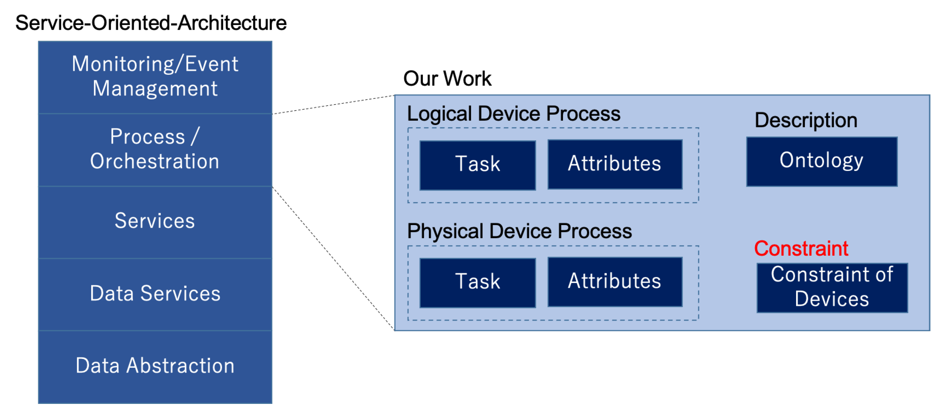
2.1. Service-Oriented-Architecture
2.2. Data Petri Net
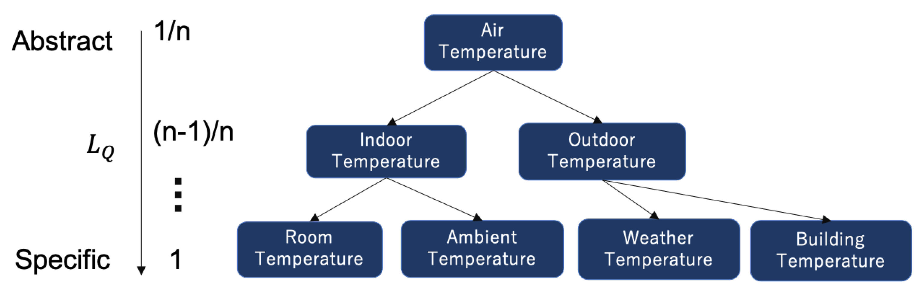
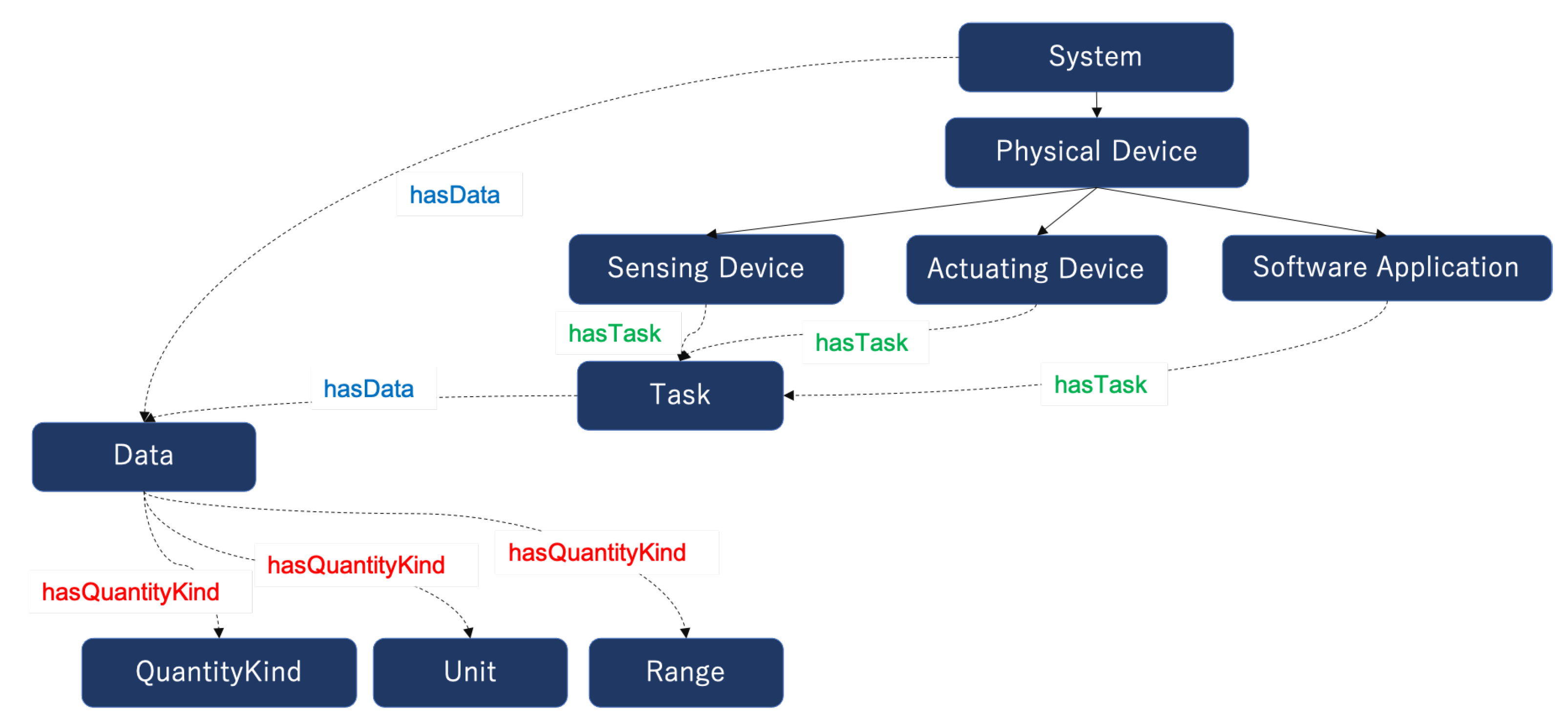
2.3. Ontology Tree
3. Related Work
4. Problem Statement
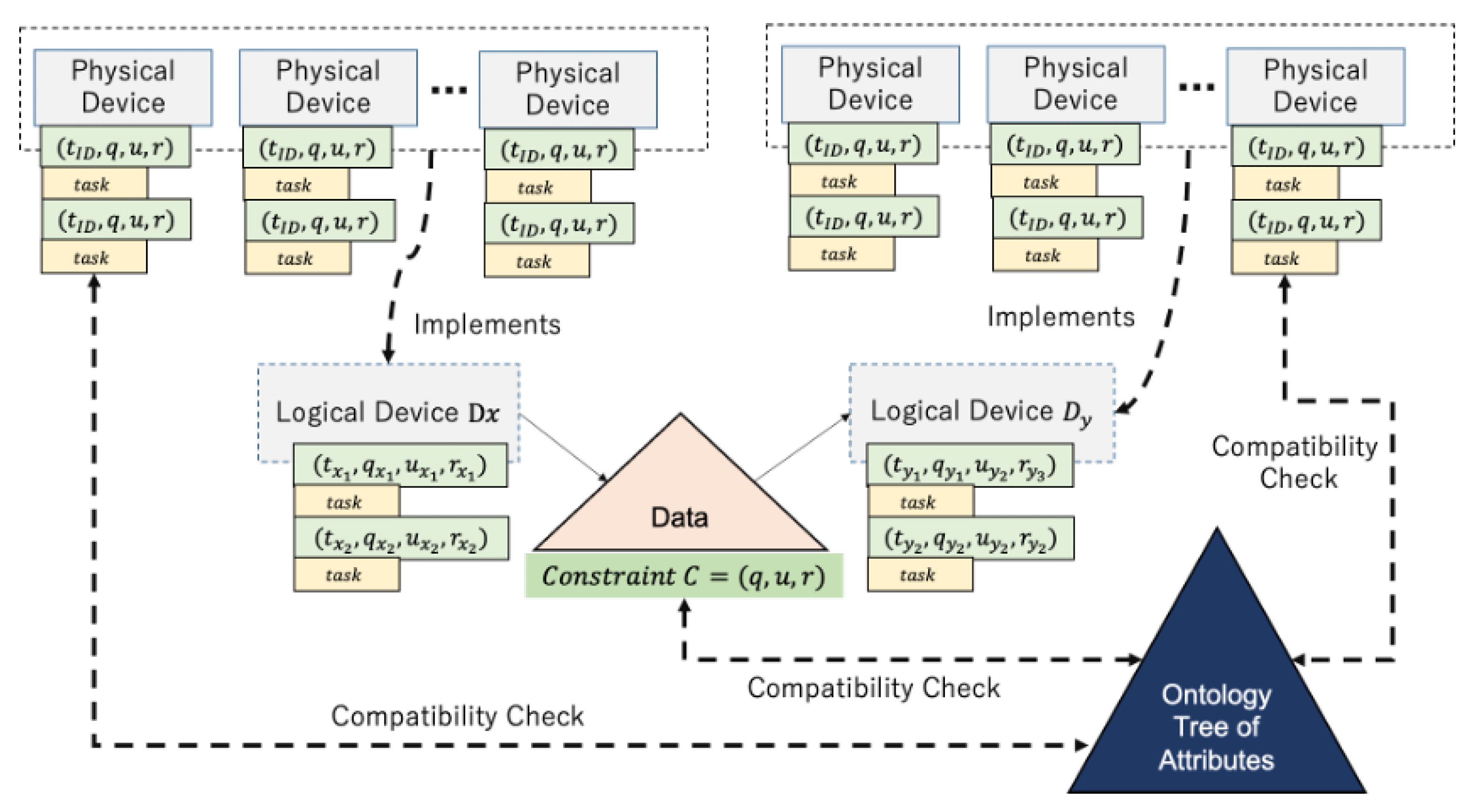
- (i)
- Physical device p satisfies the constraint C of a logical device d i.e., for all tasks of , the attributes satisfy the attribute conditions ; and
- (ii)
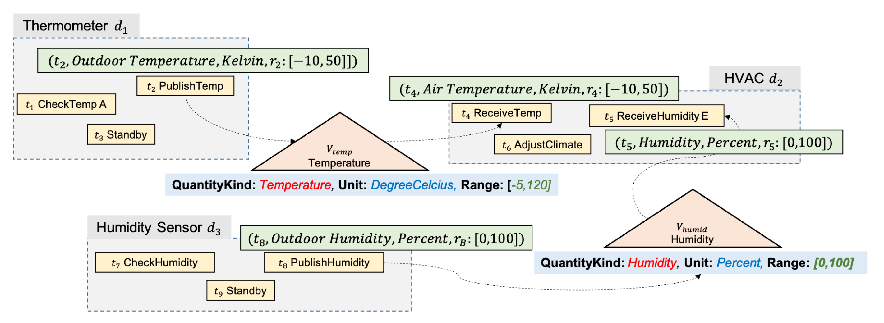
- For all relation of input/output between logical devices and data variables such that , where and are logical devices that output and input variables V, when and the set of capabilities , and satisfies the constraint
- Input: Service Design with logical devices , set of physical devices , set of device assignment of physical devices to logical devices such that
- Output: Is the set of physical devices P compatible for ?
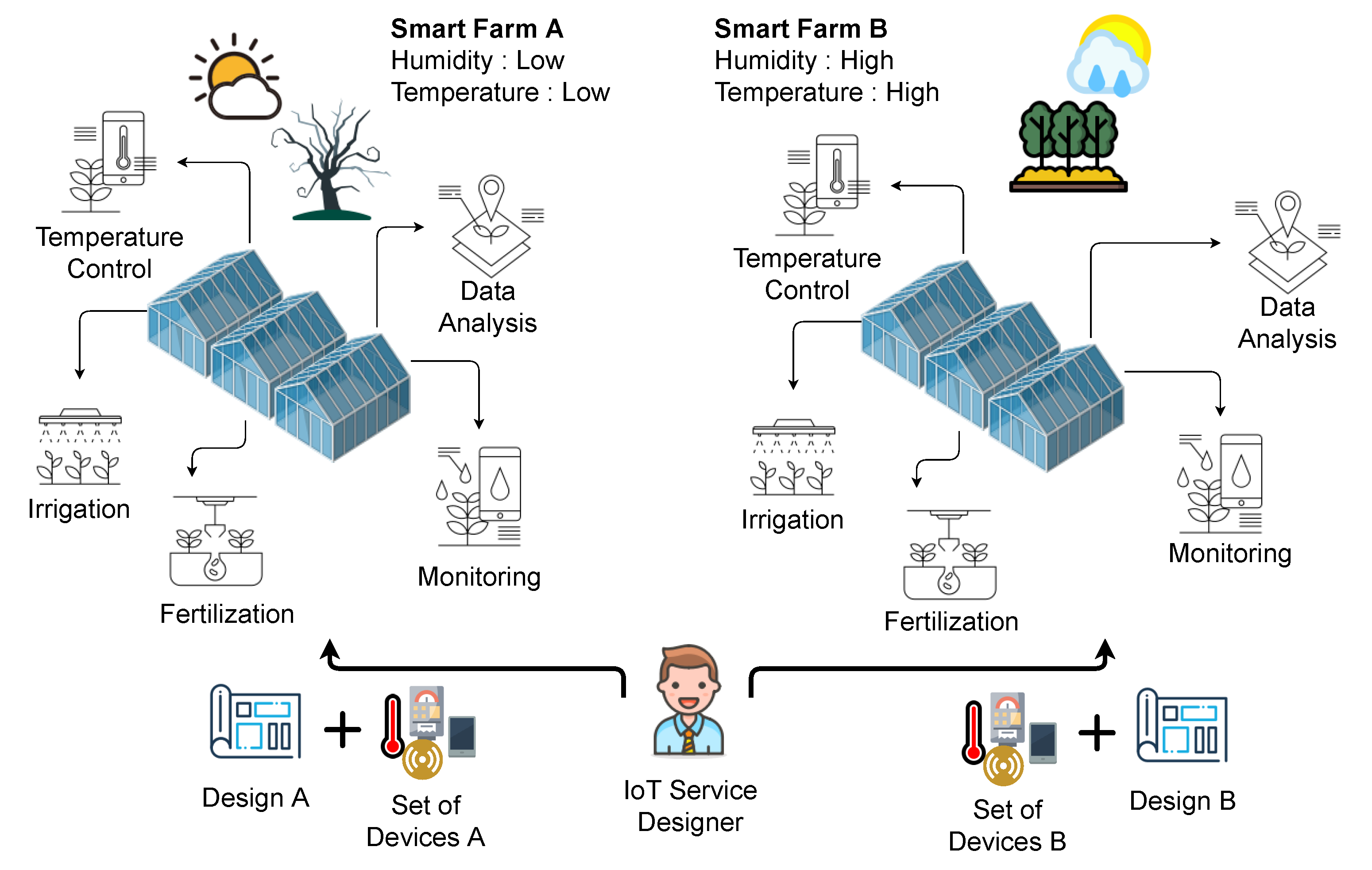
5. Concept and Approach for Design Once, Provide Anywhere
5.1. Concept Overview
5.2. Our Approach
- 1°
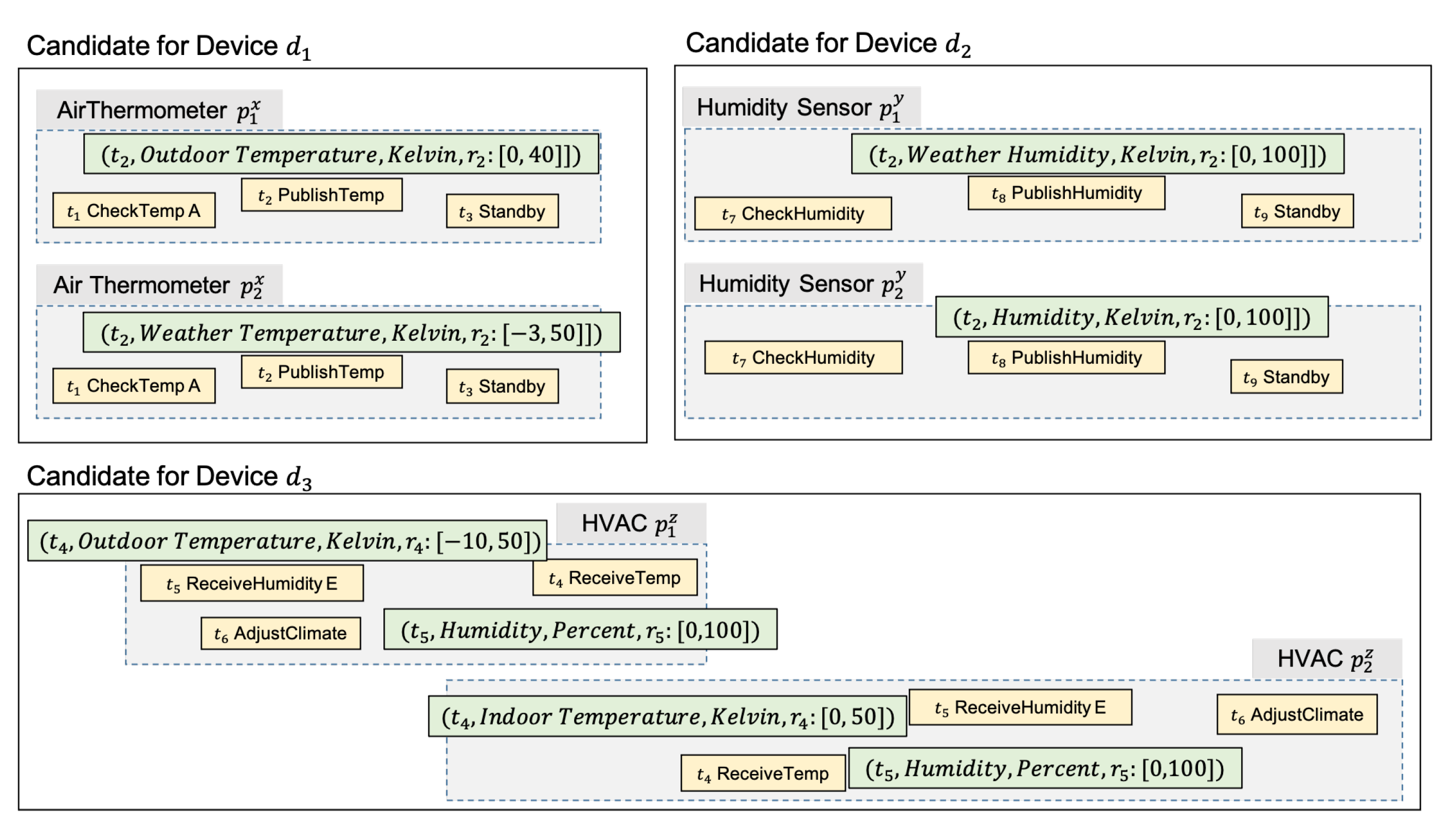
- Check the compatibility based on Definition 7 for all .
- 1-1
- Check if the constraint of a logical device i.e., for all tasks of , the attributes satisfy the attribute conditions . If no, then, output ’no’ and stop.
- 1-2
- Check for all relations of input/output between logical devices and data variables such that , where and are logical devices that output and input variables V, when and , the set of capabilities and satisfies the constraint . If no, then output ’no’ and stop.
- 2°
- Output ’yes’ and stop.
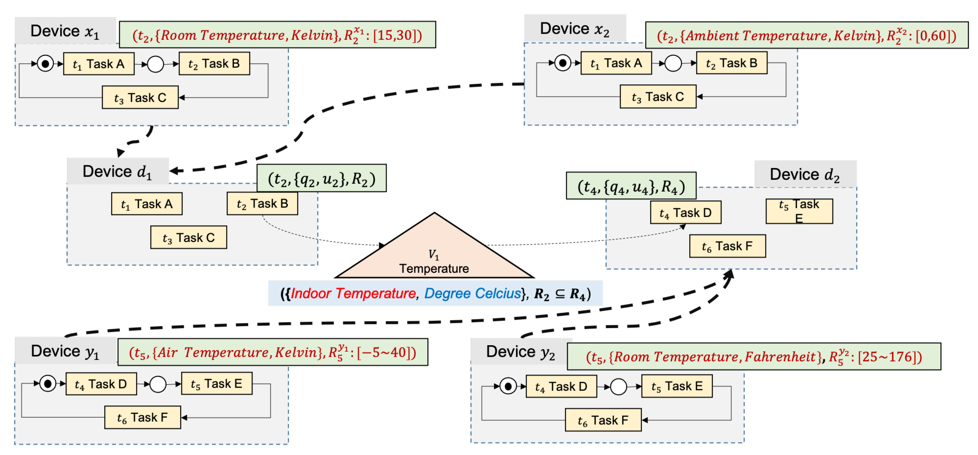
6. Application Example
7. Implementation of Elgar Platform for Design Once, Provide Anywhere
- Designer: The service designer role is to design the specification of the service. Specification includes a list of required logical devices and services, a description of the service design, and the service’s data and control flow model. The designer selects the logical device or service required for the service and designs the data control flow. Register the designed documents in the marketplace and make them available to manufacturers and users.
- Manufacturer: The device manufacturer produces Elgar Platform-compatible devices. The compatible devices must be able to communicate with the platform through the Elgar API. In order to manufacture a connectable logical device, an API connecting the logical device and the platform is used.
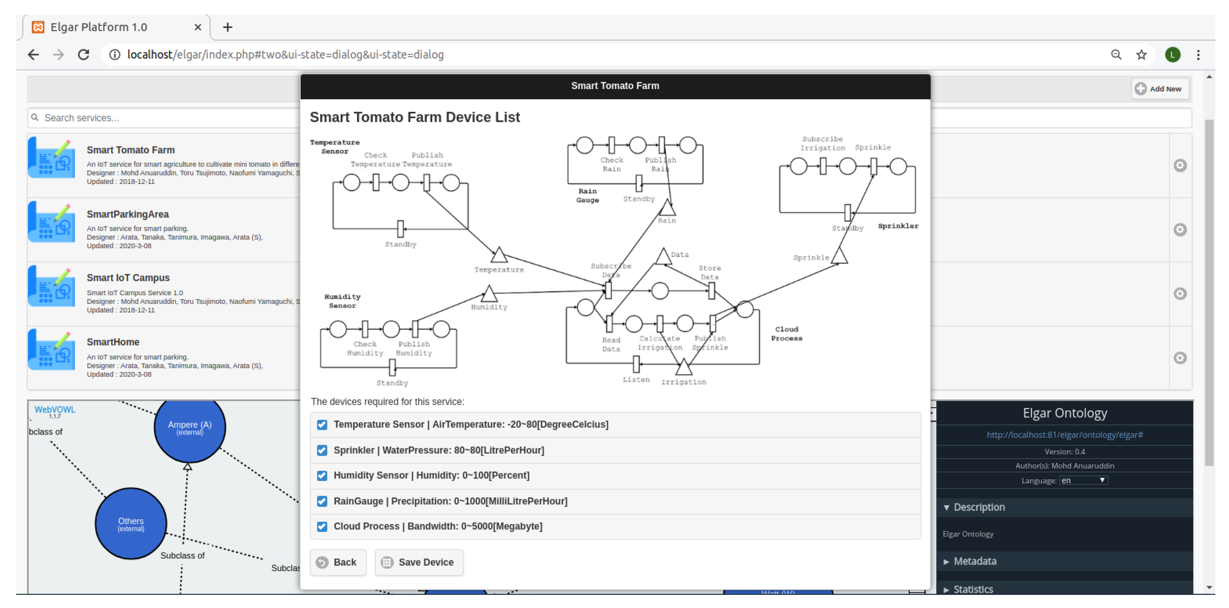
- End-User: The end-user can purchase both service design and devices required for the implementation of the IoT services from the marketplace. Using the Elgar Platform, they can implement the in-a-box solution for the required IoT service. When implementing the service, they download the necessary service design documents from the marketplace and connect the purchased logical device using the platform. The user can adapt the service by inputting environmental parameters.
7.1. Designer’s Tools

7.2. Manufacturer’s Tool
7.3. End-User’s Tool
8. Case Study and Discussion
- (i)
- Implementation of service in different environments and evaluating the quality of service.
- (ii)
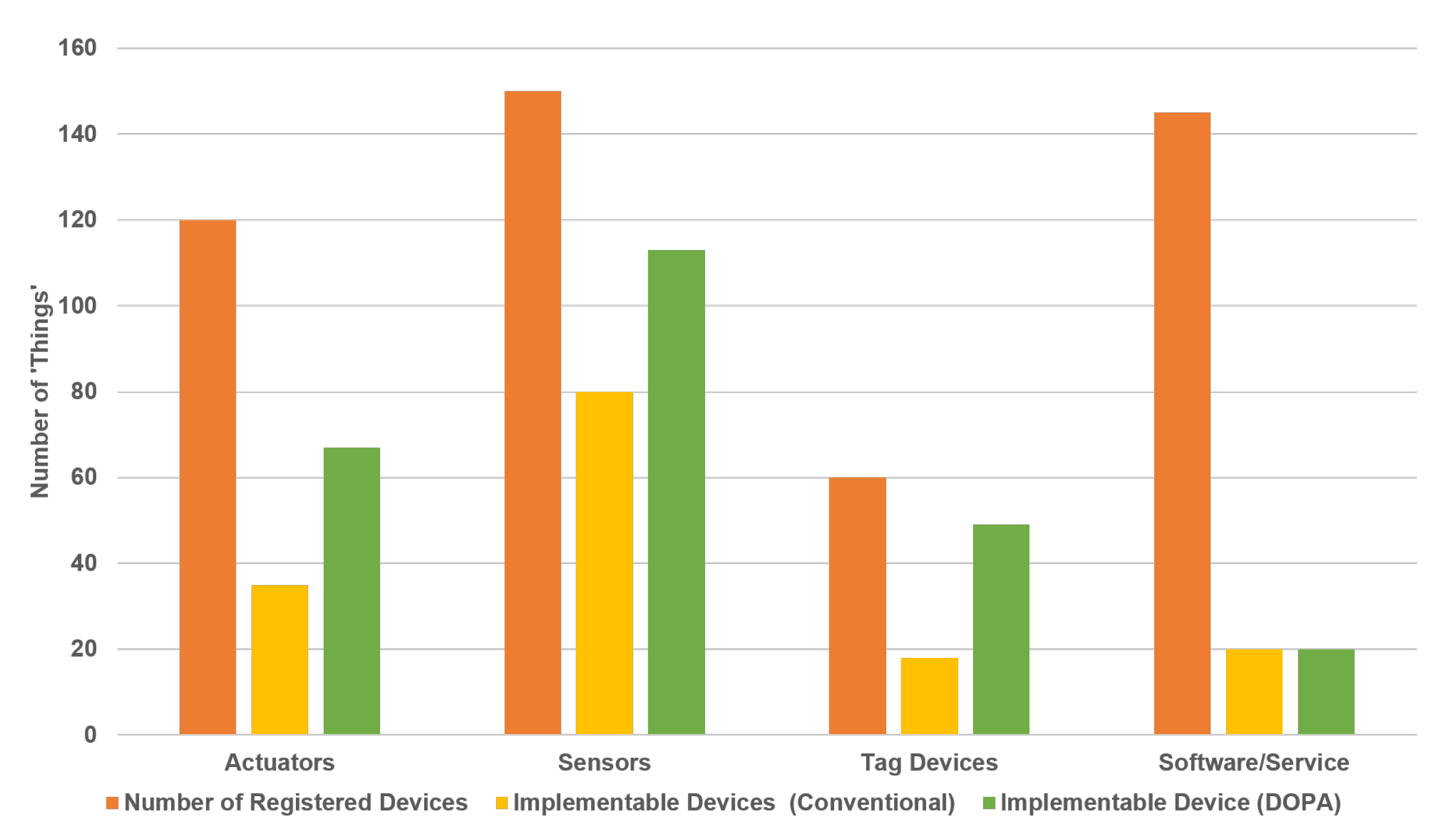
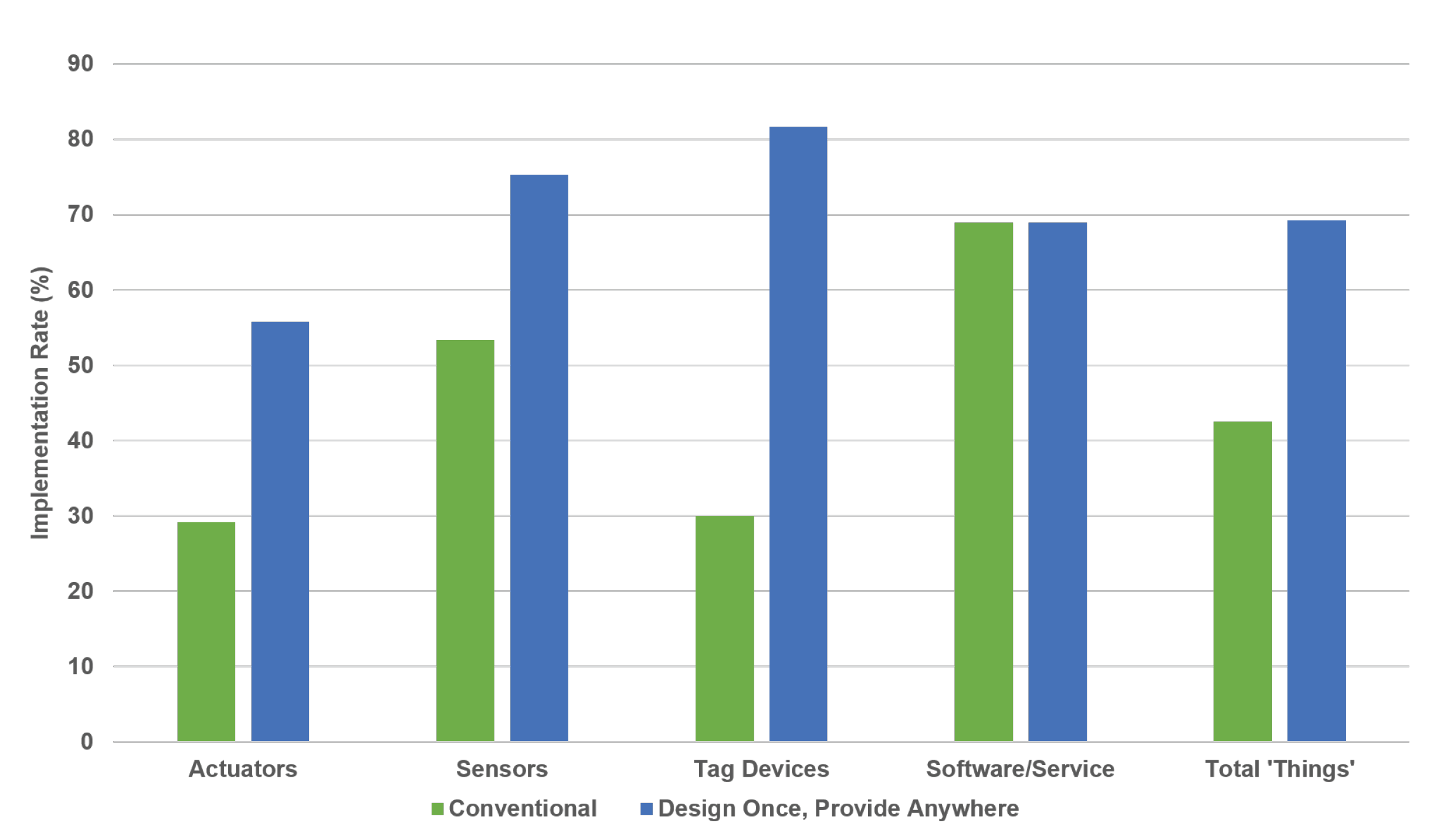
- Evaluating the rate of implementable ’things’ for a service design and comparing it to the conventional method.
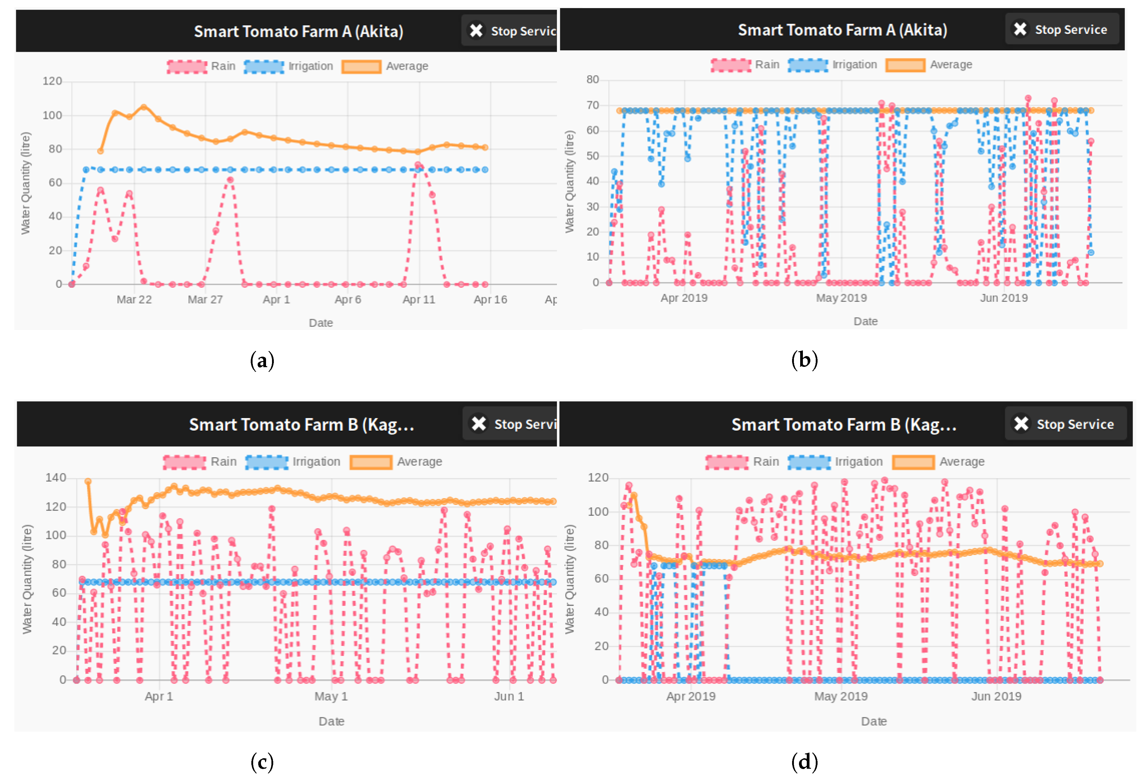
8.1. Implementation of IoT System with Environment Parameters
8.2. Evaluation of the Design Once, Provide Anywhere Concept
9. Conclusions
Author Contributions
Funding
Data Availability Statement
Acknowledgments
Conflicts of Interest
References
- Kagermann, H.; Lukas, W.; Wahlster, W. Germany: Industrie 4.0; 2017; Available online: https://ec.europa.eu/growth/tools-databases/dem/monitor/sites/default/files/DTM_Industrie%204.0.pdf (accessed on 30 November 2020).
- Matt, C.; Hess, T.; Benlian, A. Digital Transformation Strategies. Bus. Inf. Syst. Eng. 2015, 57, 339–343. [Google Scholar] [CrossRef]
- Ponnusamy, K.; Rajagopalan, N. Internet of Things: A Survey on IoT Protocol Standards. In Progress in Advanced Computing and Intelligent Engineering, Advances in Intelligent Systems and Computing; Springer: Berlin/Heidelberg, Germany, 2017; Volume 564. [Google Scholar]
- MQTT. Available online: http://mqtt.org/ (accessed on 30 November 2020).
- CoAP. Available online: https://coap.technology/ (accessed on 30 November 2020).
- Thingsworx. Available online: https://www.ptc.com/en/products/iiot (accessed on 30 November 2020).
- Thingspeak. Available online: https://thingspeak.com/ (accessed on 30 November 2020).
- NEC WISE. Available online: https://www.nec.com/en/global/solutions/iot/iotplatform/index.html (accessed on 30 November 2020).
- Bosch IoT Suite. Available online: https://www.bosch-iot-suite.com/ (accessed on 30 November 2020).
- Mindsphere. Available online: https://new.siemens.com/global/en/products/software/mindsphere.html (accessed on 30 November 2020).
- Niknejad, N.; Ismail, W.; Ghani, I.; Nazari, B.; Bahari, M.; Hussin, A.R.B.C. Understanding Service-Oriented Architecture (SOA): A systematic literature review and directions for further investigation. Inf. Syst. 2020, 91, 101491. [Google Scholar] [CrossRef]
- Kohar, R. IoT systems based on SOA services: Methodologies, Challenges and Future directions. In Proceedings of the 2020 Fourth International Conference on Computing Methodologies and Communication (ICCMC), Erode, India, 11–13 March 2020; pp. 556–560. [Google Scholar]
- Azzedin, F.; Eltoweissy, M.; Khwaja, S. Overview of service oriented architecture for resource management in p2p systems. In The Handbook of Research on P2P and Grid Systems for Service-Oriented Computing: Models, Methodologies and Applications; IGI Global: Hershey, PA, USA, 2010. [Google Scholar]
- Washizaki, H.; Ogata, S.; Hazeyama, A.; Okubo, T.; Fernandez, E.B.; Yoshioka, N. Landscape of Architecture and Design Patterns for IoT Systems. IEEE Internet Things J. 2020, 7, 10091–10101. [Google Scholar] [CrossRef]
- de Leoni, M.; van der Aalst, W.M.P. Data-aware process mining: Discovering decisions in processes using alignments. In Proceedings of the 28th Annual ACM Symposium on Applied Computing, SAC ’13, Coimbra, Portugal, 18–22 March 2013; pp. 1454–1461. [Google Scholar]
- Murata, T. Petri nets: Properties, analysis and applications. Proc. IEEE 1989, 77, 541–580. [Google Scholar] [CrossRef]
- IPSO Smart Object Guideline. 2017. Available online: https://omaspecworks.org/develop-with-oma-specworks/ipso-smart-objects/guidelines/ (accessed on 30 November 2020).
- OMA LightweightM2M (LwM2M) Object and Resource Registry. Available online: http://openmobilealliance.org/wp/OMNA/LwM2M/LwM2MRegistry.html (accessed on 30 November 2020).
- Compton, M.; Barnaghi, P.; Bermudez, L.; García-Castro, R.; Corcho, O.; Cox, S.; Graybeal, J.; Hauswirth, M.; Henson, C.; Herzog, A.; et al. The SSN ontology of the W3C semantic sensor network incubator group. J. Web Semant. 2012, 17, 25–32. [Google Scholar] [CrossRef]
- Bermudez-Edo, M.; Elsaleh, T.; Barnaghi, P. IoT-Lite: A lightweight semantic model for the internet of things and its use with dynamic semantics. Pers. Ubiquitous Comput. 2017, 21, 475–487. [Google Scholar] [CrossRef]
- Chong, I.; Ali, S. Technical Specification D3.3 Framework to Support Data Interoperability in IoT Environments; International Telecommunication Union (ITU): Geneva, Switzerland, 2019. [Google Scholar]
- Elsaleh, T.; Enshaeifar, S.; Rezvani, R.; Acton, S.T.; Janeiko, V.; Bermudez-Edo, M. IoT-Stream: A Lightweight Ontology for Internet of Things Data Streams and Its Use with Data Analytics and Event Detection Services. Sensors 2020, 20, 953. [Google Scholar] [CrossRef] [PubMed] [Green Version]
- Javaid, S.; Afzal, H.; Arif, F.; Iltaf, N.; Abbas, H.; Iqbal, W. CATSWoTS: Context Aware Trustworthy Social Web of Things System. Sensors 2019, 19, 3076. [Google Scholar] [CrossRef] [PubMed] [Green Version]
- Lin, K.-J.; Zhang, J.; Zhai, Y.; Xu, B. The design and implementation of service process reconfiguration with end-to-end QoS constraints in SOA. Serv. Oriented Comput. Appl. 2010, 4, 157–168. [Google Scholar] [CrossRef] [Green Version]
- Wang, P.; Ding, Z.; Jiang, C.; Zhou, M. Constraint-Aware Approach to Web Service Composition. IEEE Trans. Syst. Man Cybern. Syst. 2014, 44, 770–784. [Google Scholar] [CrossRef]
- Ahmadon, M.A.B.; Yamaguchi, S. On service orchestration of cyber physical system and its verification based on Petri net. In Proceedings of the 2016 IEEE 5th Global Conference on Consumer Electronics, Kyoto, Japan, 11–14 October 2016; pp. 1–4. [Google Scholar]
- Ahmadon, M.A.B.; Yamaguchi, S. Ontology-Supported Verification Method for Implementation of IoT Service Design with Petri Net. In Proceedings of the 2018 IEEE 8th International Conference on Consumer Electronics—Berlin (ICCE-Berlin), Berlin, Germany, 2–5 September 2018. [Google Scholar]
- World Wide Web Consortium. Available online: https://www.w3.org/ (accessed on 30 November 2020).
- OpenWeather API. Available online: https://openweathermap.org/ (accessed on 30 November 2020).


| Device | Physical Device | Physical Device | |||
|---|---|---|---|---|---|
| Room Temperature | Kelvin | Ambient Temperature | Kelvin | ||
| Logical Device | Indoor Temperature | Yes | - | Yes | - |
| Degree Celsius | - | Yes | - | Yes | |
| Device | Physical Device | Physical Device | |||
|---|---|---|---|---|---|
| Air Temperature | Kelvin | Room Temperature | Fahrenheit | ||
| Logical Device | Indoor Temperature | No | - | Yes | - |
| Degree Celsius | - | Yes | - | Yes | |
| Device | Physical Device | Physical Device | |||||
|---|---|---|---|---|---|---|---|
| Room Temperature | Kelvin | 15∼30 | Ambient Temperature | Kelvin | 0∼60 | ||
| Physical Device | Room Temperature | Yes | - | - | No | - | - |
| Fahrenheit | - | Yes | - | - | Yes | - | |
| 25∼176 (-5-40) | - | - | Yes | - | - | No | |
| Device Assignment | Device Compatibility | Device-to-Device Compatibility | Compatibility Rate | |||||
|---|---|---|---|---|---|---|---|---|
| Average | ||||||||
| 0.50 | 1.00 | 0.66 | 0.75 | 0.83 | 0.72 | |||
| 0.50 | 0.25 | 0.66 | 1.00 | 1.00 | 0.47 | |||
| 0.50 | 1.00 | 0.66 | 0.75 | 0.83 | 0.72 | |||
| 0.50 | 0.25 | 0.66 | 0.38 | 0.46 | 0.47 | |||
| 1.00 | 1.00 | 0.71 | 1.00 | 0.86 | 0.90 | |||
| 1.00 | 0.25 | 0.71 | 0.63 | 0.48 | 0.65 | |||
| 1.00 | 1.00 | 0.71 | 1.00 | 0.86 | 0.90 | |||
| 1.00 | 0.25 | 0.71 | 0.63 | 0.48 | 0.65 | |||
| Average Performance | 0.75 | 0.63 | 0.69 | 0.77 | 0.72 | 0.69 | ||
Publisher’s Note: MDPI stays neutral with regard to jurisdictional claims in published maps and institutional affiliations. |
© 2021 by the authors. Licensee MDPI, Basel, Switzerland. This article is an open access article distributed under the terms and conditions of the Creative Commons Attribution (CC BY) license (http://creativecommons.org/licenses/by/4.0/).
Share and Cite
Bin Ahmadon, M.A.; Yamaguchi, S.; Mahamad, A.K.; Saon, S. Physical Device Compatibility Support for Implementation of IoT Services with Design Once, Provide Anywhere Concept. Information 2021, 12, 30. https://0-doi-org.brum.beds.ac.uk/10.3390/info12010030
Bin Ahmadon MA, Yamaguchi S, Mahamad AK, Saon S. Physical Device Compatibility Support for Implementation of IoT Services with Design Once, Provide Anywhere Concept. Information. 2021; 12(1):30. https://0-doi-org.brum.beds.ac.uk/10.3390/info12010030
Chicago/Turabian StyleBin Ahmadon, Mohd Anuaruddin, Shingo Yamaguchi, Abd Kadir Mahamad, and Sharifah Saon. 2021. "Physical Device Compatibility Support for Implementation of IoT Services with Design Once, Provide Anywhere Concept" Information 12, no. 1: 30. https://0-doi-org.brum.beds.ac.uk/10.3390/info12010030