
Simulation and Experiment Analysis of 10 kV Flexible Grounding Device


School of Electrical Engineering, Southeast University, Nanjing 210096, China
*
Author to whom correspondence should be addressed.
Information 2021, 12(9), 384; https://0-doi-org.brum.beds.ac.uk/10.3390/info12090384
Submission received: 28 August 2021
/
Revised: 17 September 2021
/
Accepted: 17 September 2021
/
Published: 19 September 2021
Abstract
:The traditional 10 kV distribution network grounding system has some disadvantages, such as small grounding current and poor arc extinguishing effect, thus, hindering the detection of high-resistance grounding fault. Therefore, this paper studied the flexible grounding system consisting of small-resistance and active inverter in parallel. The control system comprises the compensation current calculation module, the fault detection module, and line protection strategy. During a single-phase grounding fault, the device is designed to inject a current of a given amplitude and phase into the neutral point to effectively suppress fault-point voltage and current and, meanwhile, quickly identifying the fault line or the busbar fault and then systematically protecting the distribution line. In addition, a large number of simulations have performed based on three grounding faults (metal, low-resistance, and high-resistance) and two modes (ungrounded and small-resistance grounding). The device can all be functional. Finally, a 400 V-level experimental prototype was built, and the experimental results are consistent with the simulation results, which can verify the effectiveness and feasibility of the flexible grounding device.
1. Introduction
As urban distribution network lines are gradually moving underground, research has emphasized on the electric faults due to use of longer cables and presence of larger capacitive currents. For the 10–66 kV distribution network system, the generally adopted neutral point grounding is the arc suppression coil, which is gradually eliminated. More power distribution networks are changed to small-resistance grounding system [1,2].
For the power system, from all types of faults, the probability of single-phase grounding faults is about 70% [3,4]. The traditional compensation method is not obvious for the compensation of resistive current and system active components. Thus, when a single-phase grounding fault occurs in the system, the arc extinguishing effect is not significant, and the harm to people and the power grid becomes more serious. For small-resistance grounding systems, when a high-resistance grounding fault occurs, the grounding current is very small, and it is not easy to identify the fault. If the fault is not removed quickly, it will endanger the operation of the system and cause unpredictable economic losses [5,6]. Therefore, for the 10 kV distribution network with small-resistance grounding, the question of how to quickly compensate for the fault current and fault voltage and how to effectively identify the single-phase grounding fault has become the current mainstream research.
In recent years, with the development of control technology in power electronics, scholars at home and abroad have proposed new arc-suppression technology based on a distribution network with small-resistance grounding. The authors of [7] proposed a three-phase cascaded H-bridge (CHB) converter with auxiliary sources and an arc-suppression method based on the improved finite control strategy. The weaknesses were the complexity of the structure and control strategy of the converter, and the balance of switching transitions should also be solved. The authors of [8] proposed a grounded-fault transfer device based on controllable voltage source in order to suppress the arc, but it cannot actually reduce the capacitive current. If the grounding current is large, the ground potential will rise, compromising safety. The authors of [9] used a shunt circuit breaker (SCB) to earth the faulty phase temporarily at the feeding. The major limitation was the occurrence of false fault detection under high-resistance grounding state and short circuit in non-defective lines due to resonant overvoltage interference.
Based on traditional small-resistance grounding in 10 kV distribution network, this paper studied a flexible grounding system consisting of small-resistance and an active inverter in parallel. For the control system, in the compensation current calculation module, during a single-phase grounding fault, this device is designed to inject a current of a given amplitude and phase into the neutral point, which can effectively suppress the voltage and current at the fault point. In the fault detection module, the fault line selection strategy based on wavelet packet decomposition is adopted in this paper. It can effectively perform partial analysis of non-stationary signals, decompose high-frequency signals, improve the accuracy of fault detection, quickly identify the fault line or the busbar fault, and then conduct line protection. In addition, a large number of simulations have been performed in order to compare the compensation effect of the device under different types of faults and neutral grounding modes. Whether the metal grounding, low-resistance grounding, or high-resistance grounding fault occurs, the structure of the small-resistance and the flexible grounding device in parallel can all fully compensate the fault current and quickly suppress arc. At the same time, it can also rapidly identify the faulty line and effectively protect the lines. Finally, an experimental prototype was built to verify the effectiveness and feasibility of the flexible grounding device adopted in this article.
2. Basic Principle of Flexible Grounding Device
The basic topology of 10 kV flexible grounding device is shown in Figure 1. Among them, EA, EB, and EC are the three-phase power voltages of the 10 kV distribution network; Rx (x = A, B, C) and Cx (x = A, B, C) are the equivalent resistance and equivalent capacitance of the 10kV distribution network, respectively; T is the step-up transformer of grounding transformer; R0 is the small resistance of neutral grounding; Ii is the compensation current injected by the flexible grounding device to the neutral point of 10 kV distribution network; L0 is the filter inductance; and C0 is the filter capacitance. Assuming that a single-phase ground fault occurs in phase C, Rf is the transition resistance of ground fault.
The flexible grounding device adopted in this paper is based on the active inverter, and it adopts the parallel structure of small resistance and step-up grounding transformer. The flexible grounding device consists of an active inverter, impedance grounding system (small resistance), and three-phase uncontrollable rectifier. When the distribution network works normally, the flexible grounding device is out of use. When a grounding fault occurs, the voltage at the fault point exceeds the safety threshold, and a fault arc forms at the fault point. The flexible grounding device is put into use after the switch is closed. In order to suppress the fault point voltage and to make it lower than the safety threshold, this paper adopts a flexible grounding device in order to inject zero-sequence current with controllable amplitude and phase into the neutral point of 10 kV distribution network in order to suppress the fault point current and realize voltage arc extinguishing. The flexible grounding device samples the signal data of the zero-sequence voltage and current on the line, processes and analyzes the data, and then transmits the driving signal to the power electronic device. The power electronic device can be switched into use, which can achieve the functions of fault voltage and current compensation, arc extinguishment, fault diagnosis, fault feeder identification, and fault suppression.
3. Control System of Flexible Grounding Device
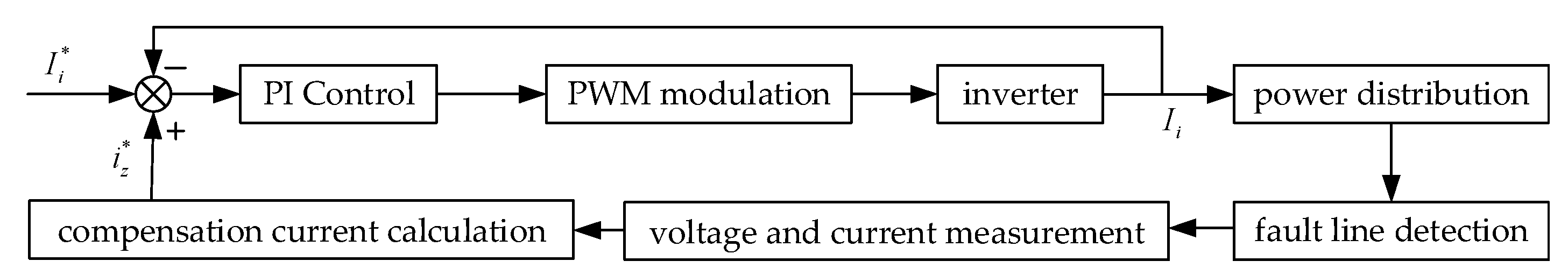
In this paper, as shown in Figure 2, the control system of the flexible grounding device includes the following: current PI controller module, PWM modulation module, fault line detection module, voltage and current measurement module, and compensation current calculation module [10,11,12].
3.1. Current PI Controller Module
The voltage and current at the fault point on the line are measured by the detection module, and the compensation current i*z is calculated. After comparing the inverter output current Ii as the feedback with the compensation current and reference current I*i, the difference is processed through the current PI controller in order to generate the inverter carrier modulation signal. After PWM modulation, the inverter outputs an ideal current Ii with a given amplitude and phase [13,14,15] and then it is injected into the neutral point of 10 kV distribution network in order to suppress the fault current and voltage to zero.
3.2. Fault Line Detection Module
When the high-resistance ground faults occur, the zero-sequence current is very small, and the change of current amplitude is not obvious, which may cause errors in fault detection [16,17,18,19,20]. Therefore, in the fault detection module, the wavelet packet decomposition is used to extract the fault characteristic signal on the 10 kV distribution line. The wavelet packet transformation actually acts similarly to a filter. The essence of its method is to firstly decompose the original fault signal into several frequency bands with the same bandwidth connecting with each other. Subsequently, the coefficients of fundamental and harmonic components are obtained in the corresponding scale space. The fundamental and harmonic signals are reconstructed to obtain the fault line signal fault detection function [16,17,18,19,20].
The fault signal f(t) is decomposed by the wavelet packet, as shown in Figure 3, which is the schematic diagram of 4-layer wavelet packet [21,22]. The decomposition algorithm is as follows:
where dj2n is No. 2n coefficient of wavelet packet on layer j. h and g are the coefficients of the wavelet decomposition of low and high pass filters, respectively.
The reconstruction algorithm of wavelet packet is as follows.
The energy Ej,k of each frequency band signal is as follows:
where djk is the kth coefficient of wavelet packet on layer j.
For the zero-sequence transient current on the 10 kV distribution network, the wavelet packet transform can effectively extract the transient characteristics of the current. During the wavelet packet transformation, the most important step is to select the appropriate wavelet base. Compared with other wavelet basis functions, the db wavelet function is more effective in extracting transient features [21,22]. After many simulations and comparisons of some wavelet functions, the db4 (4-layer wavelet packet decomposition) provided the closest waveform feature of the transient current; thus, db4 is selected as wavelet basis function in the paper. The sampling frequency is selected as 6400 Hz. Considering the boundary effect, in order to show the characteristic quantity more clearly, the waveforms of 1/4 cycle before and 3/4 cycle after the fault are extracted and transformed through the db4 4-layer wavelet packet. According to Shannon’s sampling theorem, the bandwidth of each section on the last layer is 6400/2/16 = 200 Hz. After many comparisons, this paper chooses to reconstruct the signal at (4,1), and the signal of 200–400 Hz can be accurately extracted via only one sampling period. The principle of this method is equivalent to low-pass filtering without time delay [21,22].
The specific flow of realizing the fault line detection algorithm is shown as follows. Firstly, when a single-phase grounding fault occurs, the fault zero-sequence current and fault zero-sequence voltage on 10 kV the distribution network line should be collected, and the data should be saved for at least two cycles [21,22]. In order to distinguish between ground fault and voltage imbalance, the zero-sequence voltage threshold Uset is set as 15% of the maximum phase voltage [21,22] in order to identify the ground fault from 0 to 2 kΩ. When the zero-sequence voltage exceeds the given value, the system fault is set as single-phase grounding fault. Secondly, the fault time can be determined by the wavelet singularity principle. When the zero-sequence voltage is extracted by wavelet decomposition, the modulus maximum point is determined, which corresponds to the fault time. Thirdly, the waveforms of 1/4 cycle before the fault and 3/4 cycle after the fault are extracted for analysis. The zero-sequence characteristics of k lines are extracted by db4 wavelet packet transformation, and the waveform is processed. Finally, the first-half wave method is used to identify the fault line. If the waveform direction of each line at the fault moment is consistent, the fault is considered to have occurred on the bus. If there is one line that possesses the opposite direction relative to the other lines, it is considered that the fault has occurred on this line.
3.3. Compensation Current Calculation Module
When a single-phase grounding fault occurs in phase C, Switch S is closed, and the flexible grounding device is put into use. At this time, in order to enforce the fault point voltage 0, that is, UC = 0, the neutral point voltage UN should be adjusted, that is, UN = −EC [15,23,24]. At this time, the current Ii injected into the neutral point by the flexible grounding device is as follows.
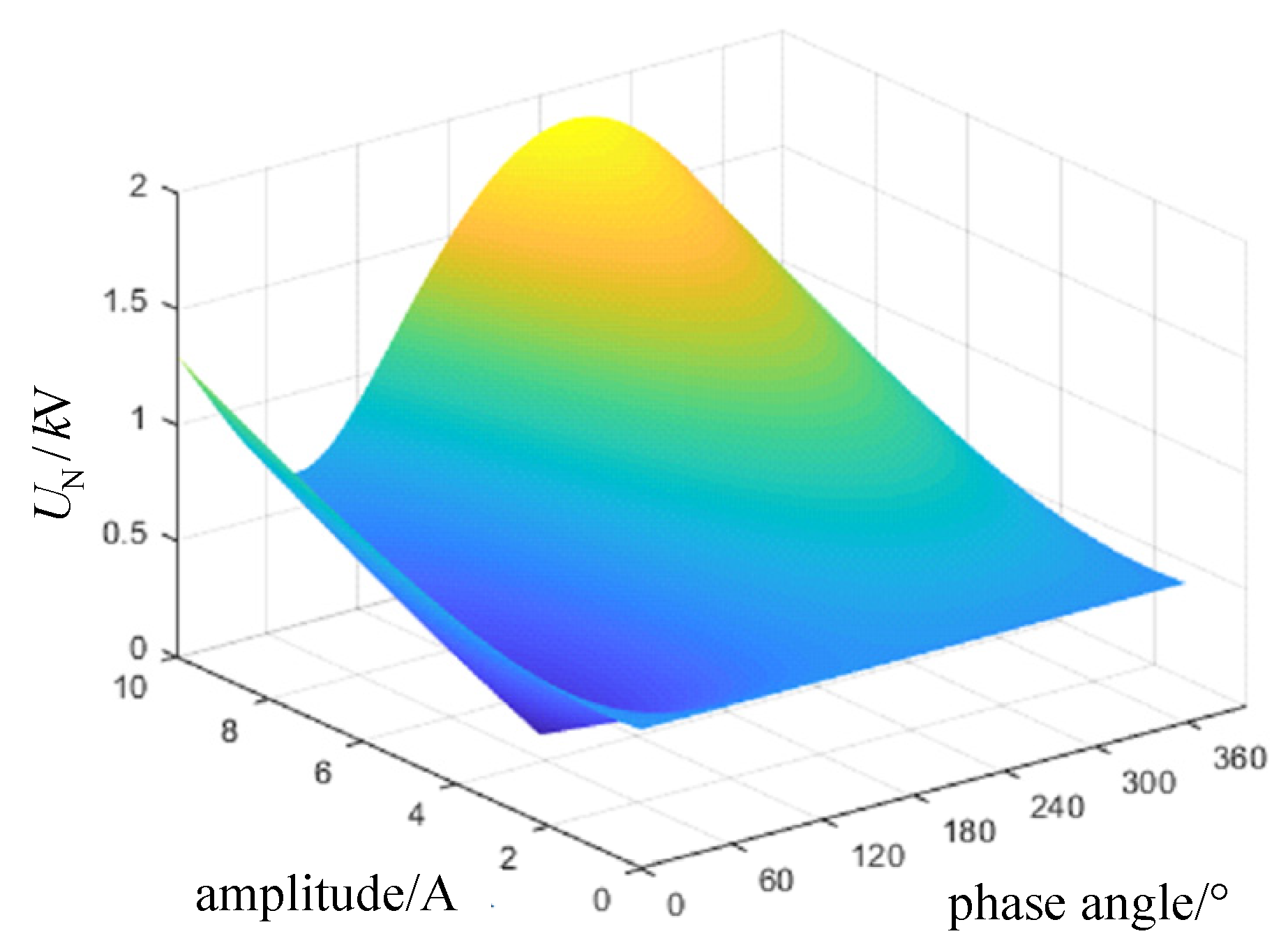
According to Formula (4), the current Ii is irrelevant to fault transition resistance Rf [25,26,27]. The injected current can fully compensate the active and reactive components of the fault current. Thus, it can effectively suppress the fault phase voltage to zero and realize arc extinguishment. Using the simulation parameters shown in Table 1 and bringing them into Equation (4), the relationship between neutral point voltage UN and neutral point injection current Ii can be obtained, as shown in Figure 4 and Figure 5.
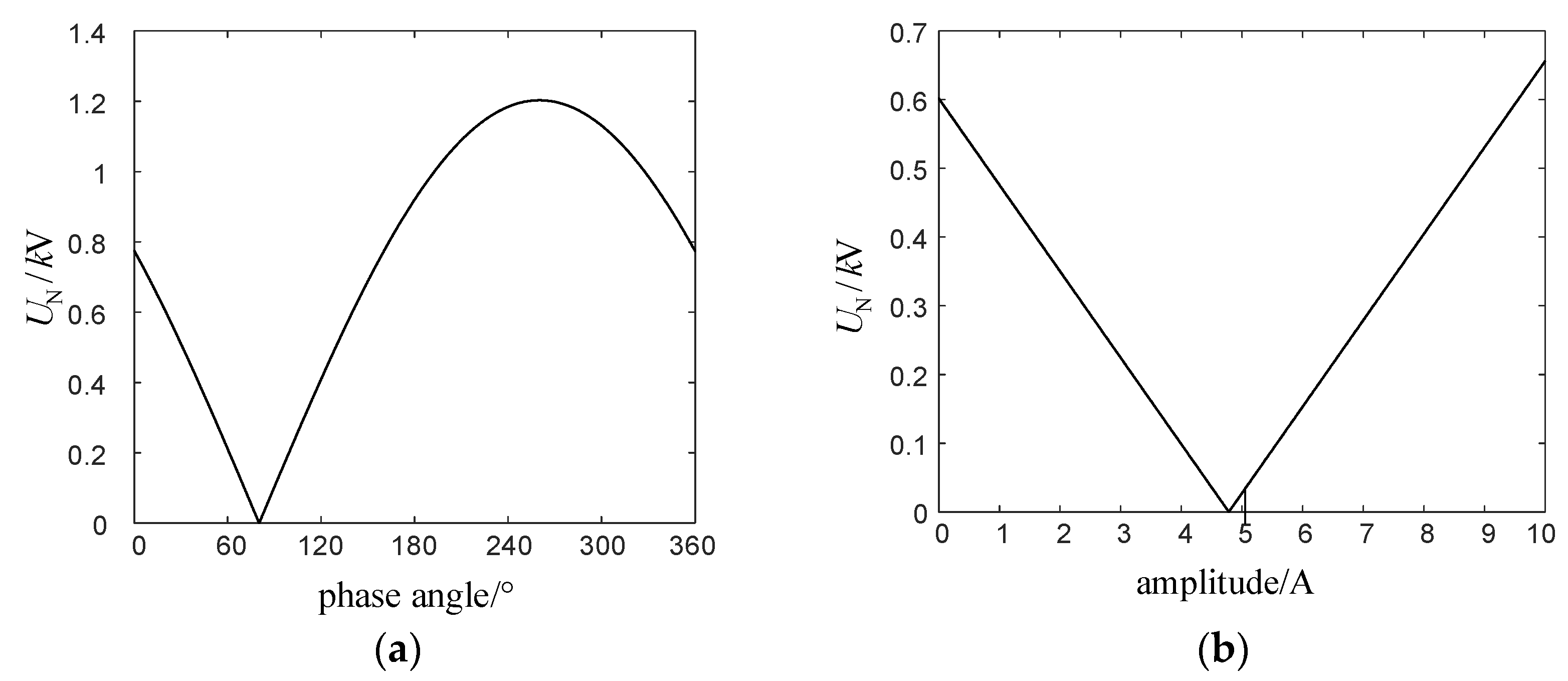
It can be observed from Figure 4 and Figure 5 that when the current Ii with amplitude of 4.78 A and phase of 80.2° is injected through the neutral point, the fault phase voltage UN is forced to be zero, and the fault point current is zero, which achieves the purpose of full compensation of fault residual current and realizes arc extinguishment at the fault point.
3.4. Line Protection Strategy
The flow of control strategy and line protection strategy of flexible grounding device is shown in Figure 6. After the fault detection process, if the faulty line k is identified, the switch is on, and the flexible grounding device is put into use. The compensation current i*z is calculated. After comparing the inverter output current Ii as the feedback with the compensation current and reference current I*i, the difference is processed through the current PI controller to generate the inverter carrier modulation signal. After PWM modulation, the inverter outputs an ideal current Ii with a given amplitude and phase. It can force the fault phase voltage to zero. After a time delay, if the zero-sequence voltage is reduced proportionally with the current Ii, this means that the arc is extinguished at the fault point [23,24]. Then, the switch is closed, and the flexible grounding device is out of use. Otherwise, it is considered that the fault is permanent, and the fault line should be isolated.
4. Simulation Results
4.1. Compensation Characteristics of Flexible Grounding Device
The simulation model of the 10 kV flexible grounding device as shown in Figure 1 was built by MATLAB software. In order to verify the effectiveness of the flexible grounding device used in this paper under three different fault types (metal grounding fault, low-resistance grounding fault, and high-resistance grounding fault) and two different grounding modes (ungrounded mode and small-resistance grounding mode), a large number of simulation analyses were carried out in this paper, and the compensation results were compared before and after the flexible grounding device was put into use. Due to the space limitation of the article, only the waveforms under metal grounding (grounding fault transition resistance Rf = 0 Ω) and small-resistance grounding mode were taken as an example in Figure 7, and the rest waveforms are not shown in this paper. At 0.04 s, the single-phase grounding fault is set to occur on Phase-C, and at 0.1 s, the flexible grounding device is put into use. All the simulation parameters and results are presented in Table 2.
It can be observed from Figure 7 and Table 2 that the system adopts small-resistance grounding mode, and the single-phase metal grounding fault occurs in Phase-C. After the fault occurs, UC drops to 0, and UA and UB increase sharply. When the flexible grounding device is out of use, the peak value of neutral point voltage UN reaches 681.6V, and its offset rate reaches 11.83%. The maximum value of fault current is 19.5 A. After the flexible grounding device is put into use, a current Ii with amplitude of 4.78 A and phase of 80.2º is injected into the neutral point. The peak value of neutral point voltage UN remains under 5.2 V, and its offset rate reaches 0.086%. The suppression effect of neutral point voltage is remarkable, and the fault current remains only at 0.33 A, approaching zero, which destroys the mechanism of arc resignation and realizes arc extinguishment.
It can be observed from Table 2 that whether it is metal, low-resistance, or high-resistance grounding fault, when the flexible grounding device is put into use, it can effectively suppress the current at the fault point and force it to zero. It can also realize full compensation of residual current at the fault point and realize 100% arc extinguishment of transient fault. Compared with ungrounded mode and small-resistance grounding mode, the use of small-resistance grounding mode combined with flexible grounding device has better effects on suppressing residual current at fault point and higher reliability of arc extinguishment.
4.2. Fault Dectection of Flexible Grounding Device
In this paper, the simulation model of transformer substation with four lines on the 10 kV bus side was built, and the equivalent parameters of each line are different. Assuming that a single-phase grounding fault occurs on one line or on the busbar, the fault line can be identified by using the strategy based on wavelet packet transformation. The waveforms of zero-sequence current on each line before and after fault are shown in Figure 8 and Figure 9.
It can be observed from Figure 8 and Figure 9 that the change rates of the non-fault line waveforms are basically the same, but the zero-sequence capacitive current of the fault line is the opposite of the sum of the non-fault lines. The current of the fault line is the sum of the capacitive current, inductive current, and the current on the grounding resistance, but the inductive current and resistive current have little impact on the capacitive current. Thus, there is a significant difference in the change rate and amplitude of the fault line current during the transient process.
By using the above strategy, the fault line can be identified by different current directions at the fault moment. When the grounding fault happens on one line, the coefficient diagram of wavelet packet decomposition and reconstruction is shown in Figure 10. It can be observed that, at the fault moment, the waveform directions of fault line and non-fault line are opposite to one another. When the grounding fault happens on the bus, the coefficient diagram of wavelet packet decomposition and reconstruction is shown in Figure 11. Since the bus fault is equivalent to single-phase short-circuit grounding fault on all lines, the waveform directions of each line are the same. This method can identify whether the line fault or the busbar fault occurs and can also effectively detect the fault line k.
5. Experiments
In order to further verify the effectiveness of the strategy adopted in this paper, an experimental prototype with 400 V voltage level was built, and its control board uses DSP and FPGA dual controller. The experimental parameters are shown in Table 3. The experimental prototype is mainly composed of a distribution grid module, isolation transformer, controller module, inverter module, and rectifier module. The physical picture of the experimental prototype is shown in Figure 12.
The experimental waveforms are shown in Figure 13. From top to bottom, they are waveforms of inverter output voltage Ui, three-phase voltage UABC0 (between lines and the neutral point) of distribution network, fault phase current If, fault phase voltage Uf, and three-phase current IABC of distribution network.
It can be observed from Figure 13 that, after the fault occurs, the fault phase voltage Uf fluctuates only within 20 ms. Before the flexible grounding device is put into use, the fault current If is 15.66 A. After the flexible grounding device is put into use, the fault current If is 0.396 A, which means that the fault current is effectively suppressed. Furthermore, the fault phase voltage Uf is also suppressed, which is consistent with the waveform UC in Figure 7a The experimental results are consistent with the simulation results; thus, it can be verified that the flexible grounding device adopted in this paper can effectively suppress the voltage and current at the fault point in the case of a single-phase grounding fault occurring in distribution network, which represents the effectiveness and feasibility of the device.
6. Conclusions
The flexible grounding system consisting of small-resistance and active inverter in parallel is adopted in this paper. Its control system contains the compensation current calculation module and the fault detection module. During a single-phase grounding fault, this device is designed to inject a current of a given amplitude and phase into the neutral point, which can effectively suppress the voltage and current at the fault point. This device can also quickly identify the fault line or the busbar fault, and then effectively conduct line protection. In addition, a large number of simulations have been performed under different fault types and neutral grounding modes. Finally, a 400 V-level experimental prototype was built, and the experimental results are consistent with the simulation results, which can verify the effectiveness and feasibility of the flexible grounding device. Due to the fact that the school laboratory does not have the conditions for experimental verification of the content of fault detection and line protection, in the future, we will cooperate with a power grid company to conduct further experiments.
Author Contributions
Conceptualization, M.L., C.Z. and K.L.; methodology, M.L. and C.Z.; software, C.Z.; validation, K.L.; formal analysis, M.L., C.Z. and K.L.; writing—original draft preparation, M.L.; writing—review and editing, M.L., C.Z. and K.L.; supervision, K.L. All authors have read and agreed to the published version of the manuscript.
Funding
This research received no external funding.
Institutional Review Board Statement
Not applicable.
Informed Consent Statement
Not applicable.
Data Availability Statement
The data presented in this study are available upon request from the corresponding author.
Conflicts of Interest
The authors declare no conflict of interest.
References
- IEEE Draft Standard for Requirements, Terminology, and Test Procedure for Neutral Grounding Devices Amendment: Neutral Grounding Resistors Section (AM)-Amendment 1; IEEE PC57.32a/D11.2; Institute of Electrical & Electronics Engineers: Piscataway, NJ, USA, 2020; pp. 1–16.
- Zhou, Y. Research on Neutral Voltage Offset and Its Influencing Factors of 20kV Small Resistance Grounding System. In Proceedings of the 2020 IEEE International Conference on High Voltage Engineering and Application (ICHVE), Beijing, China, 6–10 September 2020; pp. 1–4. [Google Scholar]
- Barik, M.; Gargoom, A.; Mahmud, M.; Haque, M.; Al-Khalidi, H.; Oo, A.M.T. A Decentralized Fault Detection Technique for Detecting Single Phase to Ground Faults in Power Distribution Systems with Resonant Grounding. IEEE Trans. Power Deliv. 2018, 33, 2462–2473. [Google Scholar] [CrossRef]
- Zhang, Q.; Zhang, Y.; Song, W.; Fang, D. Transmission feeder fault location for single-phase-to-earth fault on non-direct-ground neutral system. IEEE Trans. Power 1998, 66, 2444–2453. [Google Scholar]
- Wang, P.; Chen, B.; Tian, C.; Sun, B.; Zhou, M.; Yuan, J. A novel Neutral Electromagnetic Hybrid Flexible Grounding Method in Distribution Networks. IEEE Trans. Power 2017, 32, 1350–1358. [Google Scholar]
- Bastian, M.; Carman, W.; Woodhouse, D. Real-Time Monitoring of Substation Ground Potential Rise and Grounding System Impedance Using Power System Faults. IEEE Trans. Ind. Appl. 2015, 51, 5298–5304. [Google Scholar] [CrossRef]
- Qiu, W.; Guo, M.; Yang, G.; Zheng, Z. Model-Predictive-Control-Based Flexible Arc-Suppression Method for Earth Fault in Distribution Networks. IEEE Access 2019, 7, 16051–16065. [Google Scholar] [CrossRef]
- Liu, H.; Wang, K.; Ran, J.; Yang, Q.; He, L. Improved Scheme for Single-Ground Fault Suppression Based on Grounded-Fault Transfer Device. In Proceedings of the 2020 IEEE International Conference on High Voltage Engineering and Application (ICHVE), Beijing, China, 6–10 September 2020; pp. 1–4. [Google Scholar]
- Nikander, A. Development and Testing of New Equipment for Faulty Phase Earthing by Applying RTDS. IEEE Trans. Power Deliv. 2017, 32, 1295–1302. [Google Scholar] [CrossRef]
- Zeng, H.; Yang, P.; Cheng, H.; Xin, J.; Lin, W. Research on Single-Phase to Ground Fault Simulation Base on a New Type Neutral Point Flexible Grounding Mode. IEEE Access 2019, 7, 82563–82570. [Google Scholar] [CrossRef]
- Luo, P.; Wen, Y.; Xie, Y. A New Arc Suppression Method for Single-Phase Ground Fault of Distribution Network. In Proceedings of the 2019 IEEE PES Asia-Pacific Power and Energy Engineering Conference (APPEEC), Macao, China, 1–4 December 2019; pp. 1–5. [Google Scholar]
- Jin, H.; Gao, Z.; Zhao, J. Line Parameter Estimation of Distribution Network after Grounding Fault. In Proceedings of the 2020 IEEE Power and Energy Conference at Illinois (PECI), Champaign, IL, USA, 27–28 February 2020; pp. 1–6. [Google Scholar]
- Gargoom, A.; Amanullah, M.; Cavanagh, M. A Method for Calculating the Asymmetry in the Shunt Parameters of Power Lines in Compensated Distribution Networks. IEEE Trans. Power Deliv. 2020, 35, 2168–2176. [Google Scholar] [CrossRef]
- Chen, Y.; Lu, S.; Zhou, X.; Liang, S. Two-Phase Current Injection Method for Single Line-to-Ground Fault Arc-Suppression with Revised STATCOM. IEEE Access 2020, 8, 188299–188308. [Google Scholar] [CrossRef]
- Fan, B.; Yao, G.; Yu, K.; Zeng, X.; Wang, W.; Zhuo, C.; Guerrero, J. Principle of Flexible Ground-Fault Arc Suppression Device Based on Zero-Sequence Voltage Regulation. IEEE Access 2021, 9, 2382–2389. [Google Scholar] [CrossRef]
- Van Fleet, P.J. “Wavelet Packets,” Discrete Wavelet Transformations: An. Elementary Approach with Applications; Wiley: Hoboken, NJ, USA, 2019; pp. 427–460. [Google Scholar]
- Zhang, W.; Zhang, B.; Hu, H.; Xu, J.; Zhou, L. Application of wavelet packet analysis in phase-to-ground fault detection of distribution networks. Automat. Electr. Power. Syst. 2009, 33, 60–64. [Google Scholar]
- Costa, F.B.; Prado, R. A wavelet-based transformer differential protection with differential current transformer saturation and cross-country fault detection. IEEE Trans. Power Deliv. 2018, 33, 789–799. [Google Scholar]
- Osipov, D.; Satpaev, D.; Kisselyov, B. Analysis of Single Phase-to-Ground Fault in Mixed Neutral Ground Systems Using Wavelet Transform. In Proceedings of the 2018 International Conference on Industrial Engineering, Applications and Manufacturing (ICIEAM), Moscow, Russia, 15–18 May 2018; pp. 1–5. [Google Scholar]
- Wang, Y.; Huo, B.; Wang, H.; He, X. A New Criterion for Earth Fault Line Selection based on Wavelet Packets in Small Current Neutral Grounding System. Proc. Chin. Soc. Electr. 2004, 24, 54–58. [Google Scholar]
- Zhang, C.; Liu, K.; Zhang, S.; Liu, B.; Zhao, J. Discrete Fréchet Distance Algorithm-Based Faulty Feeder Selection Method for Flexible Grounding System in Distribution Networks. In Proceedings of the 2021 IEEE Texas Power and Energy Conference (TPEC), College Station, TX, USA, 2–5 February 2021; pp. 1–6. [Google Scholar]
- Li, B.; Zhao, J.; Liu, K.; Zhang, S.; Zhao, Y.; Jin, H. Line Selection Method of Flexible Grounding System Based on Grey T-type Correlation Degree. In Proceedings of the 2019 China Electrotechnical Society Academic Annual Conference, Dalian, China, 8–9 June 2019; pp. 26–28. [Google Scholar]
- Wang, W.; Yan, L.; Zeng, X.; Fan, B.; Guerrero, J. Principle and Design of a Single-Phase Inverter-Based Grounding System for Neutral-to-Ground Voltage Compensation in Distribution Networks. IEEE Trans. Ind. Electron. 2017, 64, 1204–1213. [Google Scholar] [CrossRef] [Green Version]
- Wang, W.; Zeng, X.; Yan, L.; Xu, X.; Guerrero, J. Principle and Control Design of Active Ground-Fault Arc Suppression Device for Full Compensation of Ground Current. IEEE Trans. Ind. Electron. 2017, 64, 4561–4570. [Google Scholar] [CrossRef] [Green Version]
- Wang, Y.; Guo, Y.; Zeng, X.; Chen, J.; Kong, Y.; Sun, S. Stator Single-Line-to-Ground Fault Protection for Bus-Connected Powerformers Based on S-Transform and Bagging Ensemble Learning. IEEE Access 2020, 8, 88322–88332. [Google Scholar] [CrossRef]
- Zeng, X.; Yu, K.; Wang, Y.; Xu, Y. A novel single phase grounding fault protection scheme without threshold setting for neutral ineffectively earthed power systems. CSEE J. Power Energy Syst. 2016, 2, 73–81. [Google Scholar] [CrossRef]
- Wang, Y.; Zeng, X.; Dong, Z.; Xu, Y.; Yuan, J.; Huang, Y. Stator Single-Phase-to-Ground Fault Protection for Bus-connected Powerformers Based on Hierarchical Clustering Algorithm. IEEE Trans. Energy Conv. 2013, 28, 991–998. [Google Scholar] [CrossRef]
Figure 1.
Topology of flexible grounding device.

Figure 2.
Control system of flexible grounding device.

Figure 3.
Schematic diagram of 4-layer wavelet packet decomposition.

Figure 4.
Relationship between neutral voltage UN and neutral injection current Ii.

Figure 5.
Relationship between the UN and the amplitude of Ii: (a) phase angle of Ii is 80.2°; (b) the amplitude of Ii is 4.78 A.
Figure 5.
Relationship between the UN and the amplitude of Ii: (a) phase angle of Ii is 80.2°; (b) the amplitude of Ii is 4.78 A.

Figure 6.
Flow chart of control strategy and fault detection algorithm.

Figure 7.
Simulation waveforms: (a) three-phase voltage UA, UB, and UC of 10 kV distribution network; (b) neutral point voltage UN; (c) fault current If.
Figure 7.
Simulation waveforms: (a) three-phase voltage UA, UB, and UC of 10 kV distribution network; (b) neutral point voltage UN; (c) fault current If.

Figure 8.
Waveform of zero-sequence current on each line (when the fault occurs on one line).

Figure 9.
Waveform of zero-sequence current on each line (when the fault occurs on the bus).

Figure 10.
Waveform of wavelet packet coefficient (when the fault occurs on one line).

Figure 11.
Waveform of wavelet packet coefficient (when the fault occurs on the bus).

Figure 12.
Flexible grounding device prototype.

Figure 13.
Experiment waveforms: (a) experiment waveforms under transient state; (b) experiment waveforms under steady state.
Figure 13.
Experiment waveforms: (a) experiment waveforms under transient state; (b) experiment waveforms under steady state.


Table 1.
Parameter settings.
| Parameters | Data |
|---|---|
| Neutral grounding resistance R0/Ω | 10 |
| Fault transition resistance Rf/Ω | 100 |
| Phase-A equivalent resistance to ground RA/kΩ | 7.5 |
| Phase-B equivalent resistance to ground RB/kΩ | 6.5 |
| Phase-C equivalent resistance to ground RC/kΩ | 5 |
| Phase-A equivalent capacitance to ground CA/μF | 0.8 |
| Phase-B equivalent capacitance to ground CB/μF | 0.82 |
| Phase-C equivalent capacitance to ground CC/μF | 0.91 |
Table 2.
Comparison of the fault current before and after flexible grounding.
| Fault Types | Grounding Fault Transition Resistance Rf/Ω | Grounding Modes | Fault Current If/A | |
|---|---|---|---|---|
| Device before Use | Device after Use | |||
| metal grounding | 0 | ungrounded | 85.68 | 0.86 |
| small-resistance grounding | 19.58 | 0.33 | ||
| low- resistance grounding | 100 | ungrounded | 77.83 | 0.34 |
| small-resistance grounding | 2.84 | 0.23 | ||
| high- resistance grounding | 1000 | ungrounded | 8.475 | 0.27 |
| small-resistance grounding | 1.42 | 0.11 | ||
Table 3.
Experimental Parameters.
| Parameters | Data |
|---|---|
| filter inductance L0/mH | 1 |
| filter capacitor C0/μF | 100 |
| neutral grounding resistance R0/Ω | 10 |
| fault transition resistance Rf/Ω | 100 |
| ratio of isolation transformer T | 1:1 |
| equivalent resistance of line /μF | 0.82 |
| equivalent capacitance of line /μF | 20 |
Publisher’s Note: MDPI stays neutral with regard to jurisdictional claims in published maps and institutional affiliations. |
© 2021 by the authors. Licensee MDPI, Basel, Switzerland. This article is an open access article distributed under the terms and conditions of the Creative Commons Attribution (CC BY) license (https://creativecommons.org/licenses/by/4.0/).
Share and Cite
MDPI and ACS Style
Liu, M.; Zhang, C.; Liu, K. Simulation and Experiment Analysis of 10 kV Flexible Grounding Device. Information 2021, 12, 384. https://0-doi-org.brum.beds.ac.uk/10.3390/info12090384
AMA Style
Liu M, Zhang C, Liu K. Simulation and Experiment Analysis of 10 kV Flexible Grounding Device. Information. 2021; 12(9):384. https://0-doi-org.brum.beds.ac.uk/10.3390/info12090384
Chicago/Turabian StyleLiu, Mengxuan, Chi Zhang, and Kangli Liu. 2021. "Simulation and Experiment Analysis of 10 kV Flexible Grounding Device" Information 12, no. 9: 384. https://0-doi-org.brum.beds.ac.uk/10.3390/info12090384
Note that from the first issue of 2016, this journal uses article numbers instead of page numbers. See further details here.