The Hydraulic Cavitation Affected by Nanoparticles in Nanofluids


1
Institute of Process Equipment, College of Energy Engineering, Zhejiang University, Hangzhou 310027, China
2
Department of Energy Sciences, Lund University, P.O. Box 118, SE-22100 Lund, Sweden
3
State Key Laboratory of Fluid Power and Mechatronic Systems, Zhejiang University, Hangzhou 310027, China
*
Author to whom correspondence should be addressed.
Computation 2018, 6(3), 44; https://0-doi-org.brum.beds.ac.uk/10.3390/computation6030044
Submission received: 4 July 2018
/
Revised: 1 August 2018
/
Accepted: 2 August 2018
/
Published: 6 August 2018
(This article belongs to the Special Issue Computational Heat, Mass and Momentum Transfer)
Abstract
:When liquids flow through a throttling element, the velocity increases and the pressure decreases. At this point, if the pressure is below the saturated vapor pressure of this liquid, the liquid will vaporize into small bubbles, causing hydraulic cavitation. In fact, a vaporization nucleus is another crucial condition for vaporizing, and particles contained in the liquid can also work as the vaporization nuclear. As a novel heat transfer medium, nanofluids have attracted the attention of many scholars. The nanoparticles contained in the nanofluids play a significant role in the vaporization of liquids. In this paper, the effects of the nanoparticles on hydraulic cavitation are investigated. Firstly, a geometric model of a perforated plate, the throttling element in this paper, is established. Then with different nanoparticle volume fractions and diameters, the nanofluids flowing through the perforated plate are numerically simulated based on a validated numerical method. The operation conditions, such as the ratio of inlet to outlet pressures and the temperature are the considered variables. Additionally, cavitation numbers under different operating conditions are achieved to investigate the effects of nanoparticles on hydraulic cavitation. Meanwhile, the contours are extracted to research the distribution of bubbles for further investigation. This study is of interest for researchers working on hydraulic cavitation or nanofluids.
1. Introduction
As throttling elements constrict the flowing area and introduce pressure drops, the fluid flow velocity increases and the pressure decreases. If the decreased pressure is below the saturated vapor pressure of the liquid, the liquid will vaporize to small bubbles, causing hydraulic cavitation. On the one hand, the cavitation may damage the hydraulic equipment. On the other hand, cavitation can be used in a variety of fields, such as sewage treatment and mass and heat transfer. Orifice plates and perforated plates are widely used to induce cavitation, and many scholars have contributed to this field.
Some researchers pay attention to the effects of orifice plate geometry parameters on hydraulic cavitation. Ebrahimi et al. [1] adopted an approach combining theoretical, numerical and experimental analyses to investigate the characteristics of high-pressure cavitating flow through a thick orifice plate, and obtained a critical ratio of downstream pressure to upstream pressure, below which cavitation will occur. Additionally, a correction for predicting the onset of cavitation was proposed. Rudolf et al. [2] conducted experiments to explore the dynamics of the cavitating flow downstream orifice plates, and differences between the single-hole and the multi-hole plates were observed. Zhang et al. [3] employed the particle image velocimetry to investigate the cavitation flow characteristics downstream different kinds of triangular multi-orifice plates, and pointed out the parameters affecting the flow characteristics. He et al. [4] investigated the hydrodynamic cavitation in a single-hole orifice plate by means of visualized experiment and numerical simulation. The effects of back pressure and cavitation number on the change of hydrodynamic cavitation were obtained.
Many scholars researched the utilization and prevention of cavitation in practice. Carpenter et al. [5] conducted experiments in detail to explore the effects of geometrical parameters on the production of oil in water emulsion, and carried out the optimized geometrical parameters. Hilares et al. [6] employed the response surface methodology to investigate the efficacy of hydrodynamic cavitation which was adopted for pretreatment of sugarcane bagasse, and they obtained the best conditions for the pretreatment. Bokhari et al. [7] applied the orifice plate to cleaner production of rubber seed oil methyl ester, and conducted a parametric optimization by response surface methodology. Karamah et al. [8] used a method of ozonation combined with hydrodynamic cavitation produced by an orifice plate to disinfect Escherichia coli bacteria, and found that the hybrid method can disinfect bacteria faster and better. Shaaban [9] optimized the orifice flowmeter for liquid hydrogen and obtained a novel orifice flowmeter of which the performance was improved significantly, and the cavitation was not detected for a high Reynolds number. Wang et al. [10] investigated the cavitating flow and cavitation-induced erosion by means of experiment, and applying three image post-processed approaches to analyze the test data. The cavitation characteristics were obtained.
Hydraulic cavitation induced by orifice plates is always compared by noises, and some scholars contribute to this field. Tao et al. [11] investigated the sound generation mechanisms of orifice plates. Qian et al. [12,13] analyzed the Mach number on multi-stage perforated plates inside a high pressure reducing valve, and put forward a method to reduce the aerodynamic noises.
The addition of nanoparticles will affect the physical properties of the base fluid, and Ghanbarpour et al. [14] investigated the thermal conductivity and viscosity of Al2O3-water nanofluid by means of experiment and theoretical study. The investigations were conducted with different nanoparticle concentration and temperature. The thermal conductivity and viscosity were found to increase with nanoparticle concentration and temperature, and some modifications of existing correlations were proposed. Ghanbarpour et al. [15] and Azmi et al. [16] investigated the nanofluid thermal properties and viscosity in the literature. In terms of nanofluids cavitation, many investigations have been carried out. Kabeel et al. [17] investigated the effects of the alumina nanoparticles concentration on the characteristics of a sharp-edge orifice flow, basing it on a model of a single-hole orifice plate, and the changes of some parameters representing the flow characteristics were obtained. Gu et al. [18] applied the acoustic method to experimentally investigate the effects of SiO2 nanoparticles on cavitation inception. The temperature and particle size were variables and the dimensionless free energy of the critical bubble was calculated in the experiments. Results showed that the SiO2 particles always promoted the cavitation inception. However, the increase of particle concentration further promoted the cavitation, while the particle size had little effect. Mahsa et al. [19,20] examined the effects of SiO2 nanoparticles on cavitation initiation in a centrifugal water pump. In the research, the nanoparticle concentration, size and fluid temperature were changed. It was found that SiO2 nanoparticles can postpone cavitation initiation and decrease the rate of cavitation growth. Additionally, with the increase of nanoparticle concentration, the bubble growth was reduced and with the increase of the nanoparticle size, the cavitation initiation was well postponed. Mehrdad et al. [21] settled a flow restrictive element to induce hydraulic cavitation, which was used to prevent nanoparticles agglomeration, in order to increase the stability and reusability of nanofluids.
In recent years, our research team has done some work on hydraulic cavitation inside globe valves and perforate plates [22]. In the previous investigation, the geometry parameters of valves, including bending radius, deviation distance, and arc curvature linked to import/export parts, were analyzed to study their effects on cavitation. To reduce the cavitation, an optimized combination of the geometry parameter and operating conditions was obtained. However, the present paper aims to analyze the effects of nanofluids on hydraulic cavitation. The hydraulic equipment used to induce the cavitation is a five-hole perforated plate. The alumina nanofluids are employed for the flow medium, of which the nanoparticle volume fraction and the particle diameter are considered as variables. Additionally, the investigation is carried out for different operating conditions (inlet pressures and temperatures) and the effects of nanoparticles under various operating conditions are also analyzed.
2. Materials and Methods
The alumina-water nanofluids used in the present paper are of different nanoparticle volume fractions and diameters. The saturated vapor pressure of alumina-water nanofluids changes with the nanoparticle volume fraction, the particle diameter and the temperature etc. Tso et al. [23] have conducted investigations on nanofluids saturated vapor pressure, and some results are listed in Table 1.
This investigation is aided by the Computational fluid dynamics (CFD) method, and the commercial software FLUENT is adopted. Because a flow channel of a pipe equipped with a five-hole perforated plate is symmetric, a symmetric model is developed, as shown in Figure 1a. The pipe diameter is 50 mm, the entrance section length is 250 mm, the export section length is 400 mm, the perforated plate thickness is 30 mm and the diameter of the holes is 4 mm. In addition, the arrangement of the five holes is depicted in Figure 1b.
The geometric model is discretized by the structured mesh. The elements located at the five holes and at the boundary layer have a smaller size to make the simulation more accurate. When the number of elements is 1,921,100 and 2,225,175, respectively, the relative difference of the cavitation number is only 0.91%, which indicates that 1,921,100 elements are sufficient for the accurate numerical simulations.
In this paper, a steady-state analysis is carried out. The Reynolds number is larger than 3000, so Realizable k-ε turbulence model is employed as the viscous model. The mixture model is adopted as the multi-phase model and the Schner-Sauer cavitation model is applied to simulate the cavitation. In order to reflect the effects of the nanoparticles on the physical properties of the nanofluids, syamlal-obrien model [24] was selected to model the kinetic part of the granular viscosity of the particles and lun-et-al model [25] was employed to compute the solids bulk viscosity. The liquid-vapor mass transfer is governed by the vapor transport equation:
where α is the vapor volume fraction, ρv is the vapor density, is the vapor phase velocity, Re and Rc are the mass transfer source terms connected to the growth and collapse of the vapor bubbles, respectively, and they are modeled based on the Rayleigh-Plesset equation describing the growth of a single vapor bubble in a liquid.
The generalized Rayleigh-Plesset equation, from which the bubble dynamics equation can be derived, is as follows:
Neglecting the second-order terms and the surface tension force, a simplified form is obtained:
where rb is the bubble radius, σ is the liquid surface tension coefficient, ρl is liquid density, vl is the liquid kinematic viscosity, Pb is the bubble surface pressure, and P is the local far-field pressure.
The Schnerr and Sauer model [26] derives the exact expressions for the net mass transfer from liquid to vapor. And the final form of this model is expressed as follows:
When ,
When ,
In terms of the boundary conditions, the inlet is set as a pressure inlet and the outlet is set as a pressure outlet. Additionally, no-slip wall boundary is applied for all walls, and the standard wall function is adopted. In order to verify the reliability of the numerical method mentioned above, a numerical simulation has been conducted, and the results are compared with a reported experiment, which was carried out by Kim et al. [27]. The comparison of experiment and numerical simulation is listed in Table 2. The maximum relative error is 9.2%, which indicates that the numerical method is reliable.
3. Results and Discussion
In this part, the contours of vapor volume fraction are extracted to investigate the distribution of vapor and the cavitation number, which is derived by Equation (6), and is used to assess whether cavitation would occur.
where is the cavitation number, is the pressure of fluid, pv is the saturated vapor pressure of fluid, is the nanofluid mixture density, and V is the flow rate of fluid. In fact, a smaller cavitation number means that the cavitation is more likely to occur.
As variables, the alumina nanoparticle volume fractions of alumina-water nanofluid are set as 0.01%, 0.1% and 0.5%, respectively, and the alumina particle diameters are set as 13 nm, 20 nm and 80 nm, respectively. Besides, the inlet pressures are set as 0.4 MPa, 0.6 MPa and 1.0 MPa, respectively, and the outlet pressure is set as 0.1 MPa, which is the atmospheric pressure. Additionally, the temperature ranges from 25 °C to 40 °C. The effects of alumina nanoparticle volume fraction and diameter for different operating conditions on cavitation are respectively discussed in the following sections.
3.1. The Effects of Nanoparticle Volume Fraction on Cavitation for Different Inlet Pressures
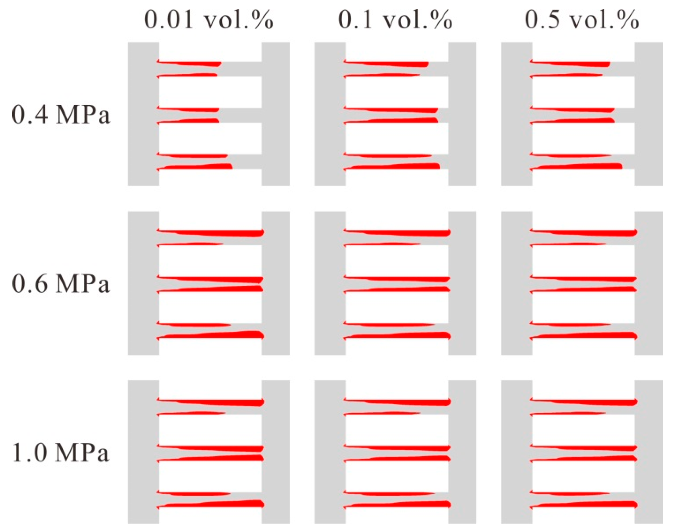
In this section, the effects of nanoparticle volume fraction on cavitation with different inlet pressures are analyzed. The nanoparticle volume fractions are set as 0.01%, 0.1% and 0.5%, respectively, and the inlet pressures are set as 0.4 MPa, 0.6MPa and 1.0 MPa, respectively. Besides, the outlet pressure is set as 0.1 MPa, the particle diameter is set as 20 nm and the temperature is set as 30 °C.
Figure 2 depicts the vapor volume fraction on the symmetric plane of the model for different nanoparticle volume fractions with different inlet pressures. In the figure, the red area represents where the vapor distributes. It is found that the vapor distributes near the wall of the holes. When the inlet pressure is 0.4 MPa, the vapor volume fraction is variable with the nanoparticle volume fraction; while when the inlet pressure is higher, for example 0.6 MPa and 1.0 MPa, the contours of vapor volume fraction are almost the same, which indicates that for a lower inlet pressure, the nanoparticle volume fraction affects the cavitation of the nanofluids, and that for a higher inlet pressure, the cavitation is dominated by the inlet pressure. According to Equation (6), the Cavitation number is inversely dependent on the flow rate. As flow rate increases, the cavitation number decreases, and cavitation becomes more serious. As in the present numerical simulation, the inlet pressure varies from 0.4 MPa to 1.0 MPa, while the outlet pressure is fixed at 0.1 MPa. As the inlet pressure increases, the pressure drop (between outlet and inlet) increases, and thus the flow rate increases. Therefore, the cavitation number decreases to generate cavitation. At relatively higher inlet pressures, the influence of inlet pressure on flow rate plays a significant role to cause cavitation, while the effect of nanoparticle volume fraction on cavitation is kind of hidden by this significant inlet pressure effect.
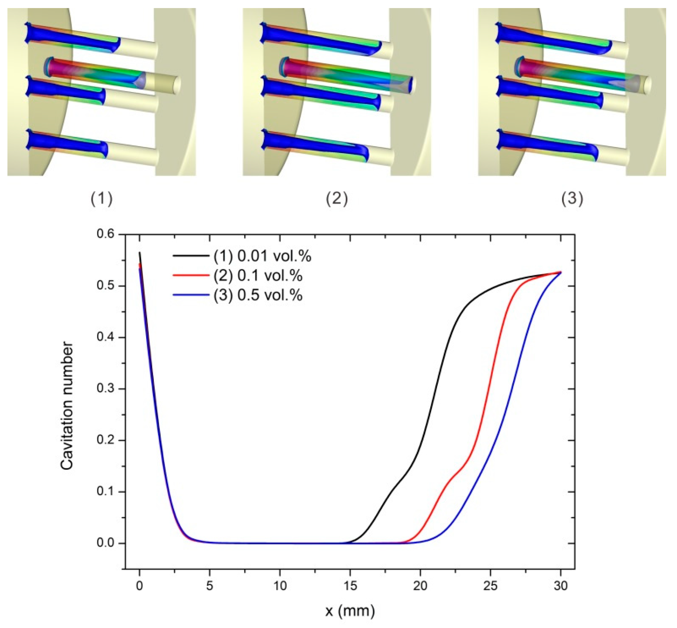
For a further investigation of the effects of nanoparticle volume fraction on the cavitation when the inlet pressure is 0.4 MPa, Figure 3 shows the cavitation number on the cross sections of the perforated plate for different nanoparticle volume fractions. The inlet of the hole is located at 0 mm, while the outlet is located at 30 mm. It is found that the cavitation number decreases abruptly when the nanofluids entering the holes, and the minimum value, which is near 0, is reached rapidly. In the former part of the hole, the cavitation number keeps very small, and it increases gradually at the latter part of the hole. It can be obtained that a larger nanoparticle volume fraction leads to a longer section where the cavitation number keeps small. That is to say, for a larger nanoparticle volume fraction, the cavitation will distribute broader. Thus, the cavitation level increases with the nanoparticle volume fraction when the inlet pressure is 0.4 MPa.
3.2. The Effects of Nanoparticle Volume Fraction on Cavitation for Different Temperatures
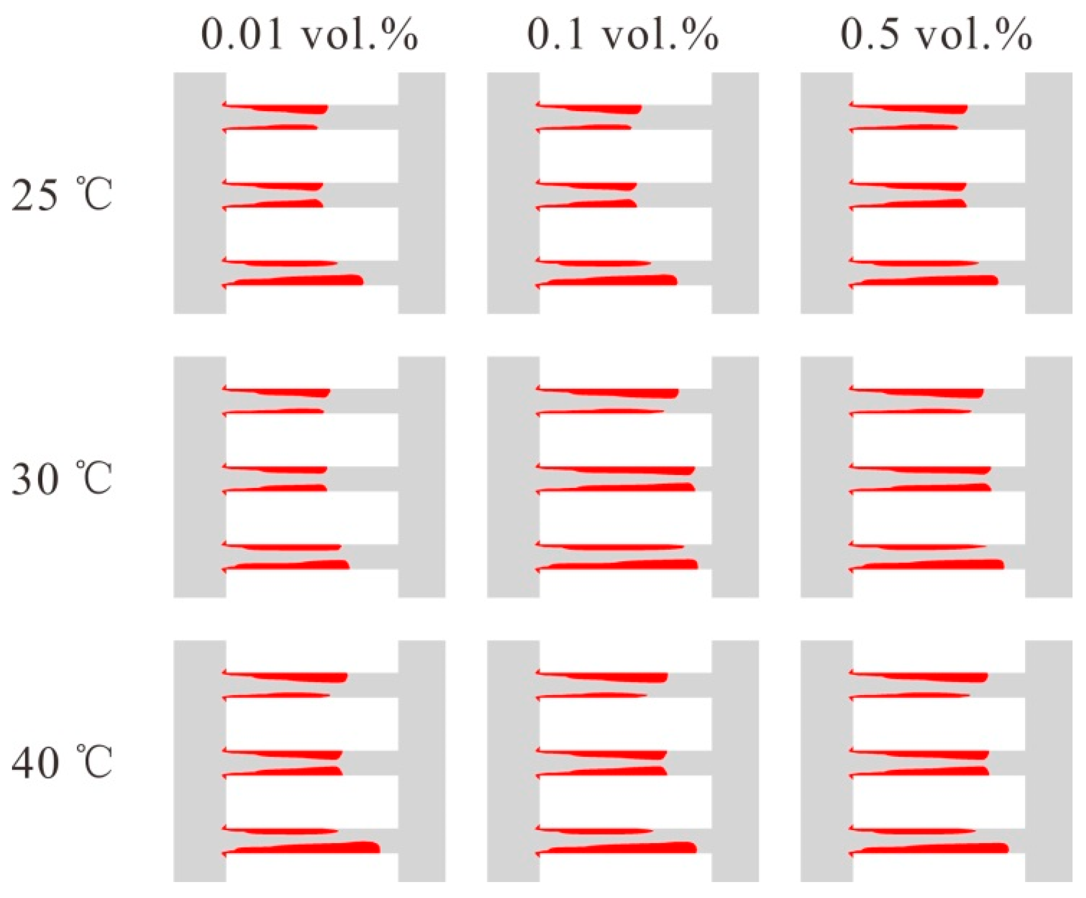
How the nanoparticle volume fraction influences the cavitation with different temperatures has been explored in this section. The nanoparticle volume fractions are set as 0.01%, 0.1% and 0.5%, respectively, and the temperatures are set as 25 °C, 30 °C and 40 °C, respectively. Additionally, the nanoparticle diameter is set as 20 nm, the inlet pressure is set as 0.4 MPa and the outlet pressure is set as 0.1 MPa.
The contours of the vapor volume fraction are shown in Figure 4. It can be obtained that in the range of the present investigation, for a fixed temperature, the vapor distribution changes with the nanoparticle volume fraction. Additionally, for different temperatures, variations of the vapor distribution with the nanoparticle volume fraction are different, which needs further investigation.
The cavitation number is analyzed for a further investigation. Figure 5a depicted the cavitation number on cross sections of the perforated plates for different nanoparticle volume fractions at different temperatures. These curves are grouped by temperature. It is found that at different temperatures, the section where the cavitation number keeps the minimum is the longest when the nanoparticle volume fraction is 0.5%, which indicates that the cavitation level is the highest. In terms of the other two nanoparticle volume fractions, the section where the cavitation number keeps the minimum is always longer when the nanoparticle volume fraction is 0.1%, and the difference is the largest at 30 °C, as shown in Figure 5b. That is to say, although a relatively higher nanoparticle volume fraction leads to a more serious cavitation, the enhancement effect changes with the temperature when the nanoparticle volume fraction is low.
3.3. The Effects of the Nanoparticle Diameter on Cavitation for Different Inlet Pressures
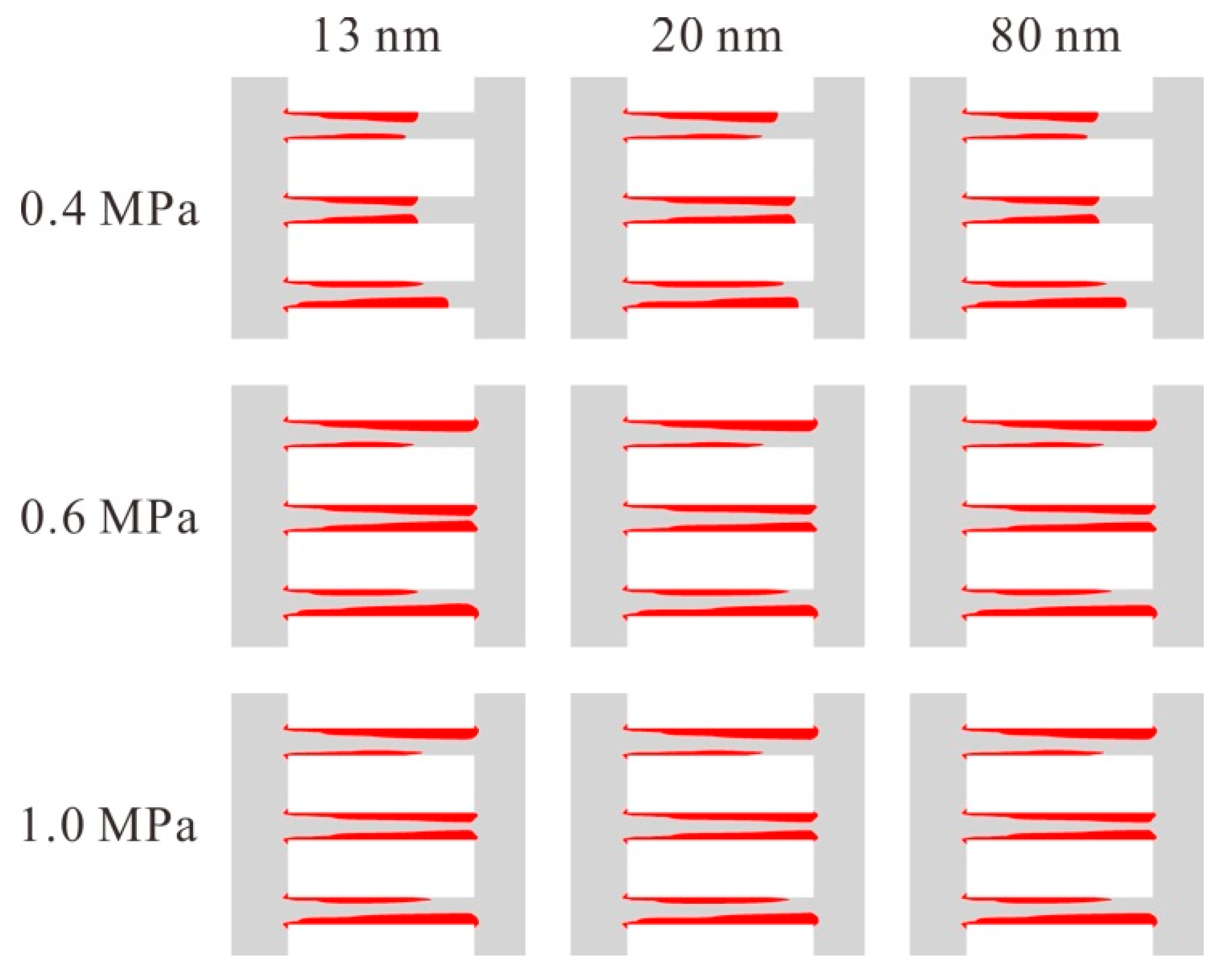
In this section, the effects of the nanoparticle diameter on cavitation with different inlet pressures are investigated. The nanoparticle diameters are set as 13 nm, 20 nm and 80 nm, respectively, and the inlet pressures are set as 0.4 MPa, 0.6 MPa and 1.0 MPa, respectively. Additionally, the nanoparticle volume fraction is set as 0.1%, the temperature is set as 30 °C, and the outlet pressure is set as 0.1 MPa.
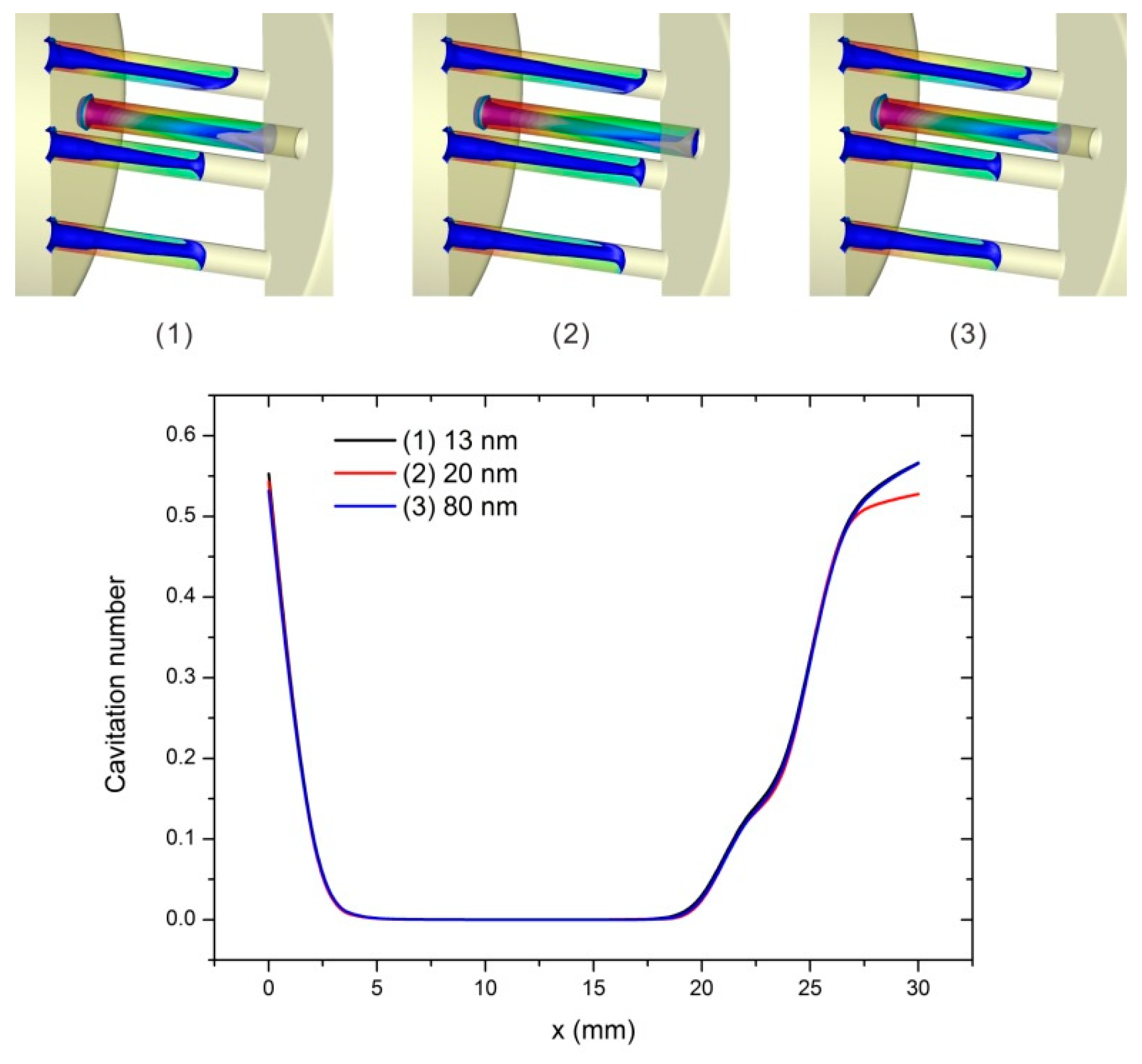
Figure 6 shows the vapor distribution on the symmetric plane of the model. It is found that when the inlet pressure is 0.4 MPa, the vapor volume fraction changes with the nanoparticle diameter. When the inlet pressures are 0.6 MPa and 1.0 MPa, the distribution of the vapor is almost the same. It indicates that for a low inlet pressure, the nanoparticle diameter impacts on the cavitation, while for a high inlet pressure, the cavitation is mainly dominated by the inlet pressure.
Fixing the inlet pressure as 0.4 MPa, Figure 7 depicts the cavitation number on cross sections of the perforated plate for different nanoparticle diameters. It is found that the three curves almost overlap. It can be obtained that for the fixed inlet pressure 0.4 MPa, the nanoparticle diameter influences the cavitation level insignificantly.
3.4. The Effects of Nanoparticle Diameter on Cavitation for Different Temperatures
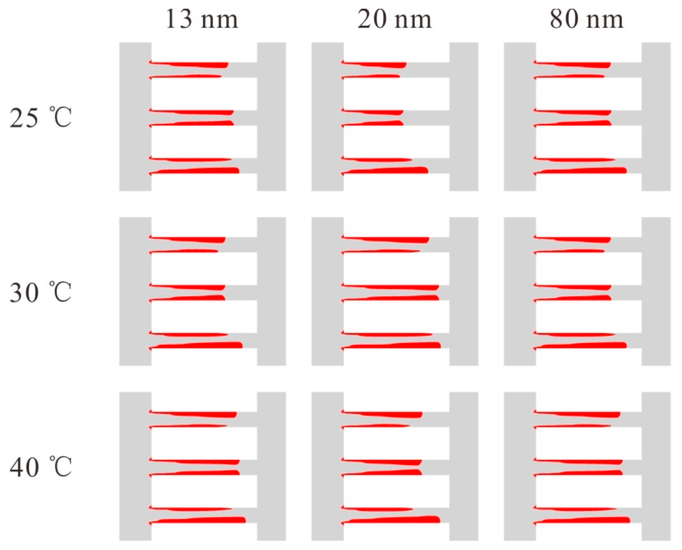
The effects of the nanoparticle diameter on the cavitation at different temperatures have been explored in this section. The nanoparticle diameters are set as 13 nm, 20 nm and 80 nm, respectively, and the temperatures are set as 25 °C, 30 °C and 40 °C, respectively. Additionally, the nanoparticle volume fraction is set as 0.1%, the inlet pressure is set as 0.4 MPa, and the outlet pressure is set as 0.1 MPa.
Figure 8 depicts the distribution of vapor for different nanoparticle diameters with different temperatures. According to Figure 8, it can be obtained that in the range of the present investigation, for a fixed temperature, the vapor distribution changes with the nanoparticle diameter. Additionally, for different temperatures, variations of the vapor distribution with the nanoparticle diameter are different, so a further exploration is needed.
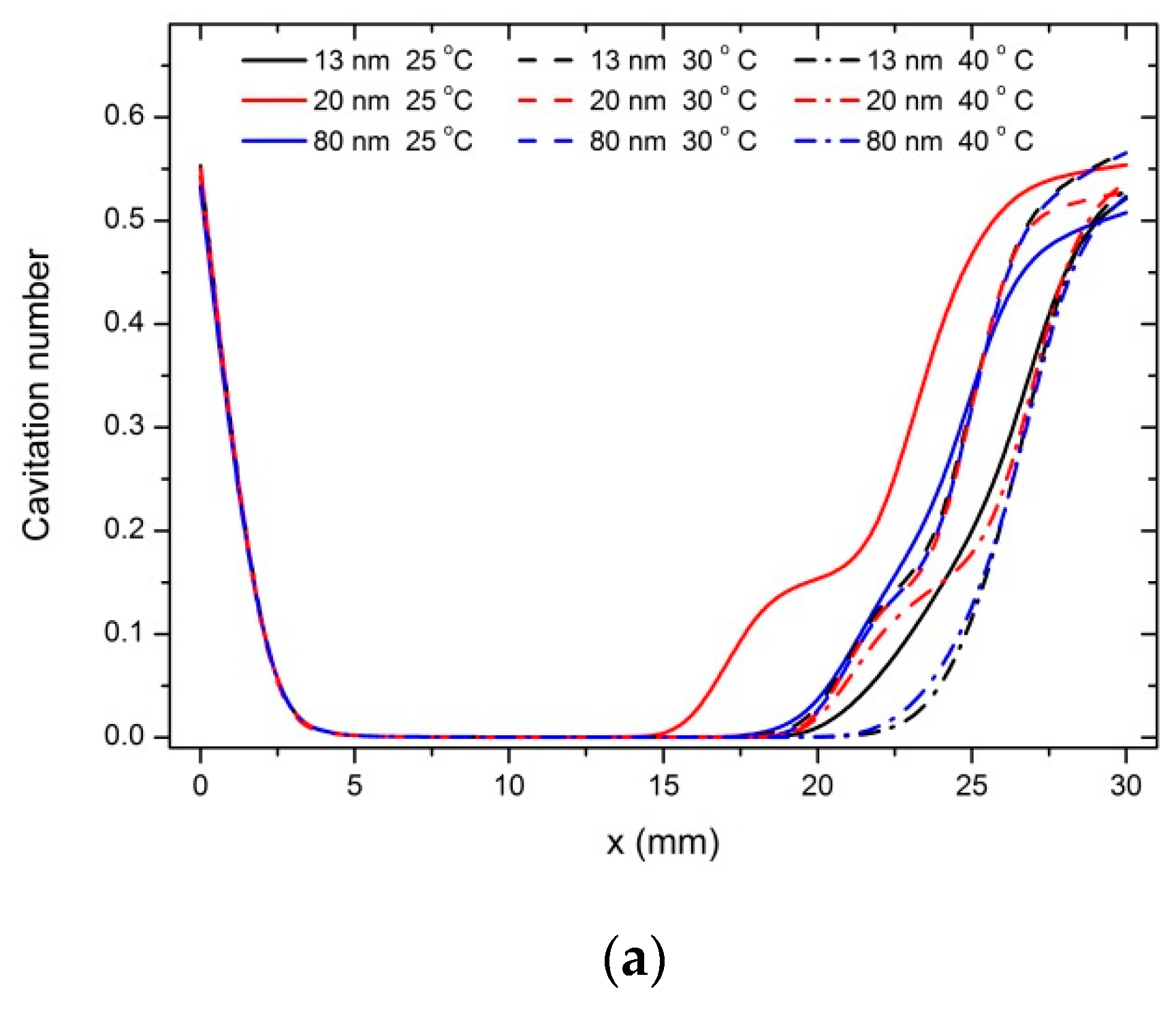
Figure 9a shows the cavitation number on cross sections of the perforated plate for different nanoparticle diameters at different temperatures, and the curves are grouped by temperature. It can be found that when the temperature is 25 °C, the difference of cavitation number for different nanoparticle diameters is the most obvious, as shown in Figure 9b. While for the other two temperatures investigated in this research, the difference is slight. That is to say, when the temperature is low, the nanoparticle diameter affects the cavitation significantly, and with the increase of temperature, the effect of the nanoparticle diameter becomes weak.
4. Conclusions
The effects of nanoparticles on hydraulic cavitation with different inlet pressures and different temperatures are investigated by numerical simulation. The nanoparticle volume fraction and diameter are variables. The vapor volume fraction and the cavitation number are analyzed, and the following conclusions can be extracted:
With a high inlet pressure, the cavitation is mainly dominated by the inlet pressure and the nanoparticle volume fraction and diameter have limited effects on the cavitation. On the other hand, with a low inlet pressure, the cavitation increases with the nanoparticle volume fraction.
In the temperature range of this investigation, the cavitation increases with the nanoparticle volume fraction; while only at 25 °C, the nanoparticle diameter affects the cavitation significantly.
Author Contributions
M.-R.C. and C.Y. conducted the investigation of this topic. M.-R.C. carried out the formal analysis. J.-Y.Q. and Z.W. researched in methodology. J.-Y.Q. and M.-R.C. wrote the original draft. B.S. and Z.W. wrote the review and editing. J.-Y.Q. and Z.-J.J. acquired the funding. Z.-J.J. and B.S. conducted the supervision.
Funding
This research was funded by the Open Foundation of the State Key Laboratory of Fluid Power and Mechatronic Systems through Grant No. GZKF-201603, the Key project of Natural Science Foundation of Zhejiang Province, China through Grant No. LZ17E050002, and the Fundamental Research Funds for the Central Universities through Grant No. 2018QNA4013.
Acknowledgments
Thanks a lot to the other members of our research team for their support of this investigation.
Conflicts of Interest
The authors declare no conflict of interest.
References
- Ebrahimi, B.; He, G.; Tang, Y.; Franchek, M.; Liu, D.; Pickett, J.; Springett, F.; Franklin, D. Characterization of High-Pressure Cavitating Flow Through a Thick Orifice Plate in a Pipe of Constant Cross Section. Int. J. Therm. Sci. 2017, 114, 229–240. [Google Scholar] [CrossRef]
- Rudolf, P.; Kubina, D.; Kozák, J.; Hudec, M.; Pochylý, F. Dynamics of the Cavitating Flow Downstream of the Orifice Plate. AIP Conf. Proc. 2017, 020033. [Google Scholar] [CrossRef]
- Zhang, K.; Dong, Z.; Zhao, W.; Ju, W.; Li, Y.; Geng, K.; Qin, Z.; Wang, L. PIV Analysis of Cavitating Water Flows Behind Triangular Multiorifice Plates. J. Hydroelectr. Eng. 2017, 36, 56–64. [Google Scholar]
- He, Z.; Zhang, X.; Chen, Y.; Ji, C. Visualization and Numerical Simulation of Hydrodynamic Cavitation in Single Hole Orifice Plate. J. Jiangsu Univ. Nat. Sci. 2017, 38, 416–422. [Google Scholar]
- Carpenter, J.; George, S.; Saharan, V.K. Low Pressure Hydrodynamic Cavitating Device for Producing Highly Stable Oil in Water Emulsion: Effect of Geometry and Cavitation Number. Chem. Eng. Proc. Process. Process Intensif. 2017, 116, 97–104. [Google Scholar] [CrossRef]
- Terãn, H.R.; de Almeida, G.F.; Ahmed, M.A. Hydrodynamic Cavitation as An Efficient Pretreatment Method for Lignocellulosic Biomass: A Parametric Study. Bioresour. Technol. 2017, 235, 301–308. [Google Scholar] [CrossRef] [PubMed]
- Bokhari, A.; Lai, F.C.; Yusup, S.; Klemes, J.J.; Akbar, M.M.; Kamil, M. Cleaner Production of Rubber Seed Oil Methyl Ester Using A Hydrodynamic Cavitation: Optimisation and Parametric study. J. Clean. Prod. 2016, 136, 31–41. [Google Scholar] [CrossRef]
- Karamah, E.F.; Ghaudenson, R.; Amalia, F.; Bismo, S. Disinfection of Escherichia Coli Bacteria Using Hybrid Method of Ozonation and Hydrodynamic Cavitation with Orifice Plate. AIP Conf. Proc. 2017, 020075. [Google Scholar] [CrossRef]
- Shaaban, S. Design and Optimization of a Novel Flowmeter for Liquid Hydrogen. Int. J. Hydrog. Energy 2017, 42, 14621–14632. [Google Scholar] [CrossRef]
- Wang, Y.; Zhuang, S.; Liu, H.; Zhao, Z.; Dular, M.; Wang, J. Image Post-Processed Approaches for Cavitating Flow in Orifice Plate. J. Mech. Sci. Technol. 2017, 31, 3305–3315. [Google Scholar] [CrossRef]
- Tao, F.; Joseph, P.; Zhang, X.; Stalnov, O.; Siercke, M.; Scheel, H. Investigation of the Sound Generation Mechanisms for In-Duct Orifice Plates. J. Acoust. Soc. Am. 2017, 142, 561–572. [Google Scholar] [CrossRef] [PubMed]
- Qian, J.Y.; Zhang, M.; Lei, L.N.; Chen, F.; Chen, L.; Wei, L.; Jin, Z. Mach Number Analysis on Multi-Stage Perforated Plates in High Pressure Reducing Valve. Energy Convers. Manag. 2016, 119, 81–90. [Google Scholar] [CrossRef]
- Qian, J.Y.; Wei, L.; Zhu, G.R.; Jin, Z. Transmission Loss Analysis of Thick Perforated Plates for Valve Contained Pipelines. Energy Convers. Manag. 2016, 109, 86–93. [Google Scholar] [CrossRef]
- Ghanbarpour, M.; Bitaraf Haghigi, E.; Khodabandeh, R. Thermal properties and rheological behavior of water based Al2O3 nanofluid as a heat transfer fluid. Exp. Therm. Fluid Sci. 2014, 53, 227–235. [Google Scholar] [CrossRef]
- Azmi, W.H.; Sharma, K.V.; Mamat, R.; Najafi, G.; Mohamad, M.S. The enhancement of effective thermal conductivity and effective dynamic viscosity of nanofluids—A review. Renew. Sustain. Energy Rev. 2016, 53, 1046–1058. [Google Scholar] [CrossRef]
- Akilu, S.; Sharma, K.V.; Baheta, A.T.; Mamat, R. A review of thermophysical properties of water based composite nanofluids. Renew. Sustain. Energy Rev. 2016, 66, 654–678. [Google Scholar] [CrossRef]
- Kabeel, A.E.; Abdelgaied, M. Study on the Effect of Alumina Nano-Fluid on Sharp-Edge Orifice Flow Characteristics in Both Cavitations and Non-Cavitations Turbulent Flow Regimes. Alexandria Eng. J. 2016, 55, 1099–1106. [Google Scholar] [CrossRef]
- Gu, Y.; Li, B.; Chen, M. An experimental study on the cavitation of water with effects of SiO2 nanoparticles. Exp. Therm. Fluid Sci. 2016, 79, 195–201. [Google Scholar] [CrossRef]
- Mahsa, E.B.; Alireza, R.; Mehdi, A. The influence of SiO2 nanoparticles on cavitation initiation and intensity in a centrifugal water pump. Exp. Therm. Fluid Sci. 2014, 55, 71–76. [Google Scholar]
- Mahsa, E.B.; Mehdi, A.; Alireza, R. Effect of SiO2 nanoparticle size on initiation and intensity of bubble formation in a water pump. Exp. Therm. Fluid Sci. 2016, 72, 40–46. [Google Scholar]
- Karimzadehkhouei, M.; Ghorbani, M.; Sezen, M.; Şendur, K.; Mengüç, M.P.; Leblebici, Y.; Koşar, A. Increasing the stability of nanofluids with cavitating flows in micro orifices. Appl. Phys. Lett. 2016, 109, 104101. [Google Scholar] [CrossRef]
- Jin, Z.; Gao, Z.; Qian, J.; Wu, Z.; Bengt, S. A parametric study of hydrodynamic cavitation inside globe valves. J. Fluids Eng. 2018, 140. [Google Scholar] [CrossRef]
- Tso, C.Y.; Chao, C. Study of Enthalpy of Evaporation, Saturated Vapor Pressure and Evaporation rate of Aqueous Nanofluids. Int. J. Heat Mass Transf. 2015, 84, 931–941. [Google Scholar] [CrossRef]
- Syamlal, M.; Rogers, W.; O’Brien, T.J. MFIX Documentation: Volume1, Theory Guide; DOE/METC-9411004, NTIS/DE9400087; National Technical Information Service: Springfield, VA, USA, 1993. [Google Scholar]
- Lun, C.K.K.; Savage, S.B.; Jeffrey, D.J.; Chepurniy, N. Kinetic Theories for Granular Flow: Inelastic Particles in Couette Flow and Slightly Inelastic Particles in a General Flow Field. J. Fluid Mech. 1984, 140, 223–256. [Google Scholar] [CrossRef]
- Schnerr, G.H.; Sauer, J. Physical and Numerical Modeling of Unsteady Cavitation Dynamics. In Proceedings of the Fourth International Conference on Multiphase Flow, New Orleans, LA, USA, 27 May–1 June 2001. [Google Scholar]
- Kim, S.M.; Bang, I.C. Hydrodynamic Cavitation Characteristics of An Orifice system and Its Effects on CRUD-Like SiC Deposition. Ann. Nucl. Energ. 2016, 96, 12–18. [Google Scholar] [CrossRef]
Figure 1.
The geometric properties of the model: (a) The geometric parameters of the model; (b) The arrangement of the five holes.
Figure 1.
The geometric properties of the model: (a) The geometric parameters of the model; (b) The arrangement of the five holes.

Figure 2.
The vapor volume fraction on the symmetric plane for different nanoparticle volume fractions with different inlet pressures.
Figure 2.
The vapor volume fraction on the symmetric plane for different nanoparticle volume fractions with different inlet pressures.

Figure 3.
The cavitation number on the cross sections of the perforated plate for different nanoparticle volume fractions when the inlet pressure is 0.4 MPa.
Figure 3.
The cavitation number on the cross sections of the perforated plate for different nanoparticle volume fractions when the inlet pressure is 0.4 MPa.

Figure 4.
The vapor volume fraction on the symmetric plane for different nanoparticle volume fractions with different temperatures.
Figure 4.
The vapor volume fraction on the symmetric plane for different nanoparticle volume fractions with different temperatures.

Figure 5.
The cavitation number for different nanoparticle volume fractions at different temperatures. (a) The cavitation on cross sections of perforated plate at different nanoparticle volume fraction and different temperature; (b) The vapor distribution and the cavitation number on cross sections of perforated plate at different nanoparticle volume fraction when the temperature is 30 °C.

Figure 6.
The vapor volume fraction on the symmetric plane for different nanoparticle diameters with different inlet pressures.
Figure 6.
The vapor volume fraction on the symmetric plane for different nanoparticle diameters with different inlet pressures.

Figure 7.
The cavitation number on cross sections of the perforated plate for different nanoparticle diameters when the inlet pressure is 0.4 MPa.
Figure 7.
The cavitation number on cross sections of the perforated plate for different nanoparticle diameters when the inlet pressure is 0.4 MPa.

Figure 8.
The vapor volume fraction on the symmetric plane for different nanoparticle diameters with different temperatures.
Figure 8.
The vapor volume fraction on the symmetric plane for different nanoparticle diameters with different temperatures.

Figure 9.
The cavitation number for different nanoparticle diameters with different temperatures. (a) The cavitation on cross sections of perforated plate at different nanoparticle diameter and different temperature; (b) The vapor distribution and the cavitation number on cross sections of perforated plate at different nanoparticle diameter when the temperature is 25 °C.


Table 1.
The saturated vapor pressure of alumina-water nanofluid [unit: Pa] [23].
Table 1.
The saturated vapor pressure of alumina-water nanofluid [unit: Pa] [23].
| Particle Diameter | Nanoparticle Volume Fraction | Temperature | ||
|---|---|---|---|---|
| 25 °C | 30 °C | 40 °C | ||
| 13 nm | 0.01% | 3176.6 | 4294.8 | 7493.3 |
| 0.1% | 3135.8 | 4222.7 | 7458.9 | |
| 0.5% | 3114.1 | 4197.7 | 7364.2 | |
| 20 nm | 0.01% | 3169.0 | 4251.8 | 7412.8 |
| 0.1% | 3173.7 | 4217.3 | 7420.2 | |
| 0.5% | 3105.1 | 4171.5 | 7333.3 | |
| 80 nm | 0.01% | 3138.5 | 4220.8 | 7395.6 |
| 0.1% | 3092.9 | 4200.1 | 7376.1 | |
| 0.5% | 3057.9 | 4137.7 | 7259.3 | |
Table 2.
Comparison of experiment and numerical simulation.
| Differential Pressure (MPa) | Experimental Mass Flow Rate (kg/s) | Numerical Simulated Mass Flow Rate (kg/s) | The Relative Error (%) |
|---|---|---|---|
| 0.49 | 2.76 | 2.99 | 8.3 |
| 0.44 | 2.65 | 2.89 | 9.2 |
| 0.40 | 2.53 | 2.73 | 7.9 |
© 2018 by the authors. Licensee MDPI, Basel, Switzerland. This article is an open access article distributed under the terms and conditions of the Creative Commons Attribution (CC BY) license (http://creativecommons.org/licenses/by/4.0/).
Share and Cite
MDPI and ACS Style
Chen, M.-R.; Qian, J.-Y.; Wu, Z.; Yang, C.; Jin, Z.-J.; Sunden, B. The Hydraulic Cavitation Affected by Nanoparticles in Nanofluids. Computation 2018, 6, 44. https://0-doi-org.brum.beds.ac.uk/10.3390/computation6030044
AMA Style
Chen M-R, Qian J-Y, Wu Z, Yang C, Jin Z-J, Sunden B. The Hydraulic Cavitation Affected by Nanoparticles in Nanofluids. Computation. 2018; 6(3):44. https://0-doi-org.brum.beds.ac.uk/10.3390/computation6030044
Chicago/Turabian StyleChen, Min-Rui, Jin-Yuan Qian, Zan Wu, Chen Yang, Zhi-Jiang Jin, and Bengt Sunden. 2018. "The Hydraulic Cavitation Affected by Nanoparticles in Nanofluids" Computation 6, no. 3: 44. https://0-doi-org.brum.beds.ac.uk/10.3390/computation6030044
Note that from the first issue of 2016, this journal uses article numbers instead of page numbers. See further details here.