Molecular Dynamics of Water Embedded Carbon Nanocones: Surface Waves Observation


1
Institute of Nanoscience and Nanotechnology INN, National Centre for Scientific Research “Demokritos”, 15310 Athens, Greece
2
Institute on Membrane Technology ITM–CNR, National Research Council, 87036 Rende, Italy
*
Author to whom correspondence should be addressed.
Computation 2019, 7(3), 50; https://0-doi-org.brum.beds.ac.uk/10.3390/computation7030050
Submission received: 2 August 2019
/
Revised: 2 September 2019
/
Accepted: 7 September 2019
/
Published: 10 September 2019
(This article belongs to the Special Issue Computational Design and Characterization of Membranes, Membrane Materials and Membrane Separation Processes)
Abstract
:We employed molecular dynamics simulations on the water solvation of conically shaped carbon nanoparticles. We explored the hydrophobic behaviour of the nanoparticles and investigated microscopically the cavitation of water in a conical confinement with different angles. We performed additional molecular dynamics simulations in which the carbon structures do not interact with water as if they were in vacuum. We detected a waving on the surface of the cones that resembles the shape agitations of artificial water channels and biological porins. The surface waves were induced by the pentagonal carbon rings (in an otherwise hexagonal network of carbon rings) concentrated near the apex of the cones. The waves were affected by the curvature gradients on the surface. They were almost undetected for the case of an armchair nanotube. Understanding such nanoscale phenomena is the key to better designed molecular models for membrane systems and nanodevices for energy applications and separation.
1. Introduction
Molecular level simulations are useful in the interpretation of experimental measurements and the validation of computational approximations and theoretical assumptions. Their indisputable utility has led to the development of a wealth of molecular dynamics (MD) codes focusing on different fields of application in chemistry. Today, the available MD software codes provide the user a prosperity for capabilities in simulation. Some codes are more solid-state oriented with a particular attention to the variety of implemented potentials. Others are mainly designed to simulate structural and dynamic properties of biomolecules with specific potentials developed for that scope [1,2,3]. The most widely used programs support a rich set of calculation types, preparation and analysis tools and almost an unlimited set of collective variables. The collective variables can be readily interpreted using custom algorithms and post processing codes aiming to extend the capabilities far beyond those allowed by straightforward molecular dynamics. Among the commonly tested analysis tools, the computation of the gyration radius () and the root mean squared displacement (rmsd) of nanoparticles are the most applied and referenced. Other important modelling schemes such as umbrella sampling and free energy calculations are well established and yet computationally demanding as they require a sequence of individual submissions of different molecular dynamics runs [4,5,6,7,8]. In all the currently available software, much effort has been devoted to the efficient exploitation of parallel computing architectures. This offers the advantage of a linear scaling reduction of computational time with the number of the applied processors. Apparently, the preference for certain MD software packages relies upon the computational performance and a versatility to interface with different software.
Molecular simulations of water–carbon interfaces such as water solvated graphitic nanosheets and carbon nanotubes (CNTs), have been a subject of intense investigation [9,10,11,12,13,14,15,16]. Unravelling the details of water confinement in small sized graphitic pores is important for diverse industrial and medical applications [17,18,19,20,21,22,23]. Most simulations argue that water dynamical properties vary substantially with pore size and report fast water transport mainly enabled by the smoothness of the carbon walls [24,25,26,27,28,29,30]. A special note has been given for narrow sized nanotubes, where it has been observed a spontaneous entry of water molecules through the rim [31,32,33]. Pristine carbon nanotubes serve as prototypes for analogous nanosized cylindrical pore channels subjected to surface functionalisation and decoration [34,35]. They are used regularly to predict how these compounds behave either when they are solvent exposed to membrane substrates or embedded in bilayer environments and polymer matrices [36,37,38,39,40]. Today, CNTs are compared to biological porins and biomimetic (artificial) water channels which undergo structural deformations such as spatial variations of the pore size and shape [41,42,43,44,45,46].
Another carbon allotrope that has attracted attention in molecular simulation studies is the carbon nanocones [47,48,49,50,51,52,53,54]. Carbon nanocones (CNCs) are cone-shaped sheets of graphene, which moderately resemble open half fullerene structures [55]. They occur in single- and multi-walled formations with different apex angles. Their surface topology comprises regular hexagonal carbon rings and 1–5 pentagonal rings concentrated near the apex [56,57,58,59]. CNCs were synthesised by accident in 1995 in the so-called Kværner Carbon Black & process, which decomposes hydrocarbons directly into carbon and [60,61]. The process under certain conditions produces a carbon material composed of microstructures, which are approximately 80% flat carbon disks, 5–15% cones with five different apex angles and 5–15% soot [62,63]. CNCs have promising properties as sensing and actuating elements in nanoscale devices [64,65]. Among these applications, their usage as atomic force microscopy (AFM) tips is of particular interest [66,67]. Based on theoretical calculations, the confinement of a carbon cone performs as a reaction nanochamber, where the reaction yields are substantially improved [68]. Recently, CNCs as well as nanohorns (i.e., sharp cones connected to a nanotube at one end) have been considered key unit components in membrane models for water treatment technologies [69].
Water scarcity is one of the major resource crisis worldwide. Only 3% of Earth’s water is fresh and suitable for human consumption. Given the abundance of salty water from seas and oceans, there is a need to purify such water using economical and environmentally-friendly processes. Seawater desalination has long been practised on this issue. The most widely used commercial desalination techniques are reverse osmosis (RO), electrodialysis and nanofiltration. They are all energy- and capital-intensive. Nanoporous membranes promise to be more efficient than the existing technology and may yield savings in energy consumption during RO operations [38,70,71,72]. Experimental and simulation studies manifest that membranes having a nanosized pore network can operate as molecular sieves, likely letting only the water molecules pass through the cavities while excluding the ions of the solvent. Carbon based membranes with micropore size distributions have earned a great merit for research on this outlook.
Conically-shaped carbon nanoparticles promise to be both high water selective and high water permeable, because of an apparent geometrical attribute. The cones are narrow at the neck and wide at the tail. The narrow neck facilitates features such as molecular sieving and the large openings at the back can serve to reduce the hydrodynamic entrance resistance [69]. Prerequisite to such expectations is that the surrounding substrate of the membrane should be impermeable to water (i.e., molecular transport will occur only through the interior of the conic pores) and that the engineered opening hole at the front should take place explicitly at the conic tip, without inducing defects on the side parts of the surface.
A complete membrane model for energy applications and separation is very complex and can be hardly implemented using molecular dynamics. One should divide the system of interest into the appropriate model constituents, which can be easily investigated, presumably due to their simplicity, stability and small size. In this respect, we used molecular dynamics of self standing carbon nanocones of different angles embedded in water. We explored the hydrophobic behaviour of conically shaped carbon surfaces and investigated microscopically the cavitation of water in a conic nano-confinement. We performed additional molecular simulations in which the carbon structures do not interact with water (as if they were in vacuum). We discuss the surface dynamic properties of the cones and demonstrate that these are different in the case of a nanotube.
2. Materials and Methods
We performed the simulations using the GROMACS molecular dynamics software (2018 series). We established a force field for the carbon nanoparticles on the basis of the OPLS-all-atom (OPLSAA) parameter set [73]. OPLSAA is a well validated atomistic force field, developed to capture the dynamic and structural behaviour of proteins. To make it functional with the carbon nanoparticles, we considered the nanoparticle a single residue and labelled their atoms using atom names and types already referenced in OPLSAA. For instance, we used the OPLSAA reference for naphthalene to set the bonded parameters (bonds, angles, torsions and connectivity) of the carbons. We modelled the non-bonded interactions of carbons, using the Lennard–Jones parameters for the aliphatic groups ( or ). We modelled the terminated hydrogen atoms as benzene hydrogens. The forcefield parameters for the nonbonded interactions are listed in Table 1. We set a zero charge on all the atoms of the nanostructures.
We used the BuildCstruct script by Andrea Minoia to build an armchair nanotube CNT(n,n) with a chiral index n = 14 [74,75]. We set the length of the tube to 3 nm. We modelled CNT(14,14), because the diameter of this nanotube, nm, is similar to the average diameter of the cone models we explored. We included terminated hydrogens on the carbons at the edges of the CNT.
To construct the carbon nanocone models, we removed 1–5 sectors of from a flat graphene disk and connected the dangling bonds. For each removed sector, we introduced one pentagon at the conic tip. The number of pentagons, , at the apex, specifies the angle of the cone, , according to: . For , we generated cones with apex angles of , , , and , respectively [48,55,57]. We only considered the cases with , 3 and 4. The pentagons were topologically isolated, meaning that each pentagonal face was surrounded by five hexagons. We used the naphthalene reference to model the bond bending and distortion of the carbon atoms. The atomic coordinates of the nanocone structures can be found online, where we also list a script to convert files with atomic coordinates to a format compatible with GROMACS [76].
We used a cubic simulation box and set the edges distant at least 1 nm from the nanoparticle. We applied full periodic boundary conditions and a minimum image convention for the interactions. Information about the nanostructures and the cubic boxes is given in Table 2. We performed short in vacuum molecular dynamics simulations to ensure that we could process the topologies correctly. Next, we inserted the water molecules in the box.
We represented water molecules using the SPC model, which is rigid and includes a single point charge (SPC) and three Lennard–Jones centres. The HOH angle was . We introduced the water molecules using the gromacs solvate command. The solvate command generated an orthogonal lattice in the box and placed the molecules on the lattice nodes. The total number of the nodes was specified by the box volume and the target density we set for the solvent. For water, the target density was 0.997 gr/cm at 300 K. We submitted the solvate command after inserting the nanoparticle in the box. As a result, some lattice nodes might overlap with the atoms of the solid and thus did not receive a molecule. Thereby, the output density of the solvate command was smaller than the actual target density. In Table 2, we list the solvate density and the number of water molecules in the cubic boxes. Later, the density was regulated when the system equilibrates in isochoric–isothermal (NVT) or isobaric–isothermal (NPT) conditions. The number of water molecules, N, was held fixed. During the NVT and NPT equilibration stages, the density was locally distributed due to the cavitation of water molecules as they interacted with the carbon walls. In NPT simulations, the box volume was allowed to fluctuate making direct changes on the total solvent density.
After solvating the box, we performed a steepest descents minimisation to make the configurational energy drop under the threshold of 100 KJ/mol. We could accomplish this in all cases in fewer than 5000 iterations. We performed a sequence of the two aforementioned equilibration steps, one in isochoric–isothermal (NVT) and one in isobaric–isothermal ensemble (NPT). The time series of the equilibration steps was 500 ps. This series was sufficient for the temperature and the box volume to converge. We reassigned the velocities every picosecond to speed up the convergence. We used isotropic scaling of the cubic volume by scaling the coordinates of molecular centres. We applied the Langevin integrator to fix the temperature and the Andersen control for the pressure. Finally, the production runs were performed in the NPT for a time series of 1 ns. This was the simulation stage where we collected the averages.
We calculated the radius of gyration using the gyrate command of GROMACS as follows:
where is the mass of atom i and is the position of atom i with respect to the centre of mass of the nanoparticle.
3. Results
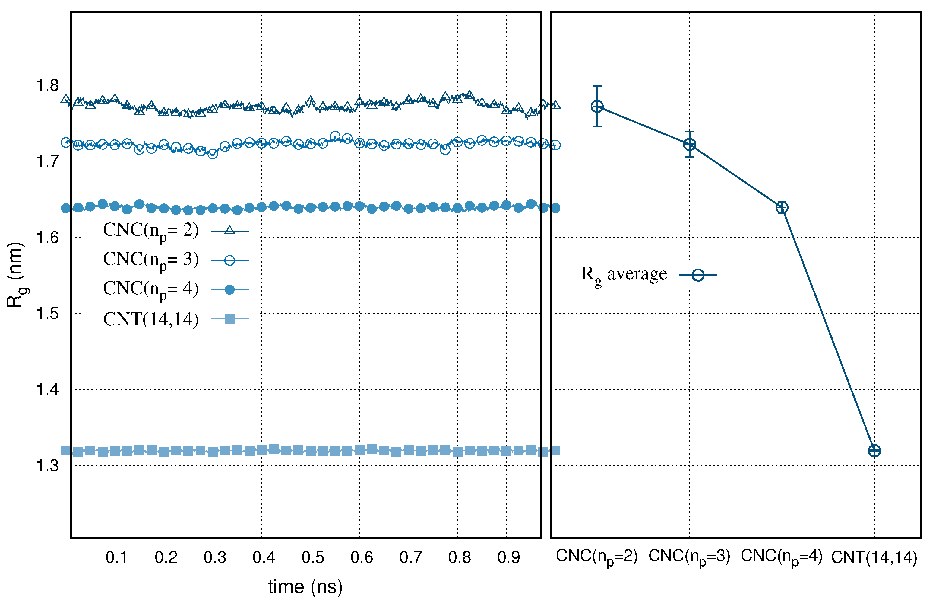
The gyration radius, , of the selected carbon nanocones and nanotube immersed in water is presented in Figure 1. At equilibrium and for a time sequence of 1 ns simulations, the gyration radius of the nanoparticles remained relatively constant. This denotes a stable folding of the carbon structures in aqueous environment. We collect the time averages of the gyration radius in Figure 1 (right). We use the y-axis error bars to express the standard deviations. We multiplied the deviations by 5.0 to guide the eye, as they would otherwise be difficult to distinguish from the line points. The standard deviations are proportional to . The radius of gyration of the carbon nanocones is appreciably higher than the CNT(14,14). The variable is a rough measure of the compactness of the particle. The actual pore shape of a nanocone is less rigid than a nanotube. The gradients in the curvature induce a bond stretching on the carbon atoms, affecting the torsion and the bond angles of the aromatic rings. Apparently, CNCs are more open structures than the CNTs. A vertical cross section of a cone, at a certain distance from the tip is wider for the cones with larger apex angles. This makes the gyration radius to increase with the cone angle.
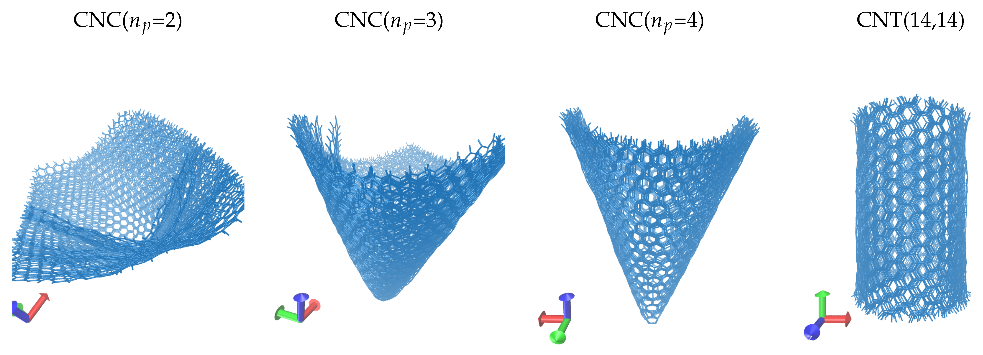
In Figure 2, we show a set of surface configurations of the carbon nanoparticles during the molecular dynamics simulations. In the simulations, the nanoparticles were assumed in vacuum as they did not interact with the environment. The figure displays ten time frames from the corresponding trajectories. The interval of the time frames is 10 ps. We fit the trajectory paths using least squares. We aligned the nanoparticle at the centre of the simulation box. When visualising continuous trajectories, centring the nanoparticle is useful for two reasons. First, it removes any periodicity effects by preventing the particle to be shown broken across the box edges. Second, it helps to highlight the relative motion of the surface atoms in respect to a configuration. We observed the waves formed on the surface of the nanostructures. The waves are more intense for the wider angle cones and almost undetected for the nanotube. This is in agreement with the results for the gyration radius, as shown in Figure 1. We also note that the conical surfaces are relatively rigid close to the tip, presumably due to the high local curvature and the strong position restrains of the carbon atoms on the pentagons. The surface waves amplify towards the cone tail, where the bonded restrictions are reduced. We assume that the bond lengths and bond angles are not equally stretched throughout the structure as they depend on the distance from the conical apex and the cone angle (or the local curvature). The surface aromatic rings can only move in groups inducing three dimensional vibrations to their neighbouring carbons. Notably, similar vibrations and shape agitations were observed on the atoms and surfaces of artificial and biological porins [44,45].
We computed the root mean squared displacement (rmsd) of CNT(14,14) and of the CNCs with different number of pentagons, on the basis of the trajectory of the nanoparticles in NPT at 1 ns. We considered two types of simulations. First, the structures were embedded in water. Second, we presumed they were in vacuum (i.e., the nanoparticles did not interact with water). All simulations were performed at equilibrium and 300 K. To compute the displacements, we used a reference configuration. The reference is a corresponding configuration from the previous NVT equilibration step and with the matching interacting environment (solvent or vacuum). The root mean squared displacements are shown in Figure 3. At equilibrium and during 1 ns, all displacements are very close to each other and almost all are below 1 Å. The small values denote that the carbon structures are very stable in water. This is expected, as the structures are all hydrophobic. The great variances during the time series, compared to the absolute values, make the different rmsd curves overlap. To clarify this, we present the time averages of rmsd and the standard deviations in Figure 3 (right), in which we can see that the particle displacements are increasing with the cone angle, presumably due to the stronger surface agitation. The nanotube is consistent to this trend, if we consider it a special case of a cone with six pentagons at the tip ( or ). The displacement of the water solvated nanoparticles is slightly further than that of when the particles are considered in vacuum. This implies that water interactions have only a negligible effect to the dynamic trajectory of hydrophobic particles.
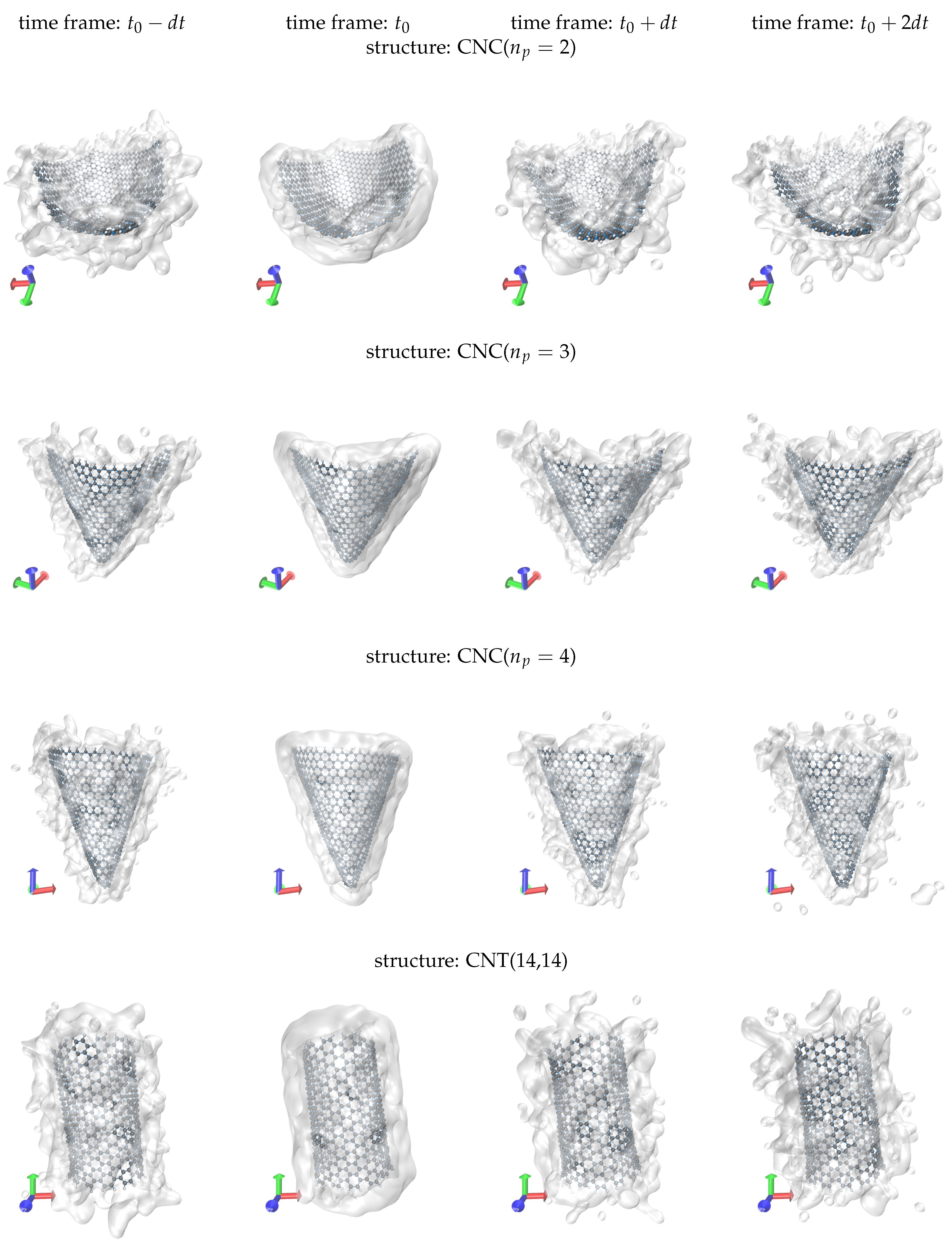
Representative screenshots for the water solvation of the selected nanoparticles are shown in Figure 4. The simulation boxes (not shown) are filled with water. However, we only show the water molecules within a distance of 5 Å of the backbone of the particle. Water is represented using a transparent surface. We settle the 5 Å water layer (hydration shell) at some time point, , of the trajectory. The snapshot configurations, shown in Figure 4, correspond to different time frames of the same trajectory. In particular, we tabulate the time frames , , and , where ps. Similar to the discussion for Figure 2, to illustrate the configurations, we apply the minimum image convention and set the centre of mass of the nanoparticles at the centre of the simulation box. The residence time of the molecules in the shell depends on the evolution of their momentum vectors throughout the simulation. At , the hydration shell appears perfectly smooth and in close contact to the solid surface. At another configuration, there is an amount of water molecules that remains within the shell, while other molecules are detached from it. We acknowledge that at the same time new molecules have entered the shell. This approves the extensive sampling in our simulations. However, we cannot capture the new entrances in the snapshots, because we only draw the molecules contained in the hydration shell at .
4. Discussion
We performed molecular simulations to shed light on the microscopic behaviour of water confined in conically shaped carbon nanopores. We detected a conspicuous pore shape agitation, which enhances with increasing the cone angle or the distance from the conic tip. The agitation implies the vibration of carbon atoms, presumably induced by the pentagonal rings (in an otherwise hexagonal network of carbon rings) concentrated near the apex of the structures. Such intense vibrations resemble the relevant surface fluctuations of artificial and biological porins. However, they are unfamiliar for other customary carbon nanostructures such as nanotubes. We highlight the contrast, presenting molecular dynamics simulations of an armchair nanotube with diameter comparable to the average diameter of the referenced cones. The surface fluctuations of the carbon cones and the rigid-like status of the nanotube are confirmed in terms of gyration radius calculations and they are manifestly explained using snapshots of time frame configurations of the simulated trajectories. Understanding such nanoscale phenomena, which are notably affected by the size, shape and geometry of the confinement, is the key to better designed molecular models as elements of membrane systems and nanodevices.
Author Contributions
Conceptualisation, A.G., A.S. and E.T.; methodology, A.G., A.S., G.K. and E.T.; visualisation, A.G. and G.K.; and writing, A.G.
Funding
The work has been funded by the project IDEA, ERANETMED2-72-357.
Acknowledgments
Calculations were performed in the High Performance Computing Services of the Greek National Infrastructure for Research and Technology, GRNET-ARIS.
Conflicts of Interest
The authors declare no conflict of interest.
References
- Bonomi, M.; Branduardi, D.; Bussi, G.; Camilloni, C.; Provasi, D.; Raiteri, P.; Donadio, D.; Marinelli, F.; Pietrucci, F.; Broglia, R.; et al. PLUMED: A portable plugin for free-energy calculations with molecular dynamics. Comput. Phys. Commun. 2009, 180, 1961–1972. [Google Scholar] [CrossRef] [Green Version]
- Abraham, M.J.; Murtola, T.; Schulz, R.; Páll, S.; Smith, J.C.; Hess, B.; Lindahl, E. GROMACS: High performance molecular simulations through multi-level parallelism from laptops to supercomputers. SoftwareX 2015, 1–2, 19–25. [Google Scholar] [CrossRef]
- Aktulga, H.M.; Fogarty, J.C.; Pandit, S.A.; Grama, A.Y. Parallel reactive molecular dynamics: Numerical methods and algorithmic techniques. Parallel Comput. 2012, 38, 245–259. [Google Scholar] [CrossRef] [Green Version]
- Niels, H.; van Gunsteren, W. Practical Aspects of Free-Energy Calculations: A Review. J. Chem. Theor. Comput. 2014, 10, 2632–2647. [Google Scholar]
- Bennett, G.H. Efficient estimation of free energy differences from Monte Carlo data. J. Comput. Phys. 1976, 22, 245–268. [Google Scholar] [CrossRef]
- Martins, S.A.; Sousa, S.F.; Ramos, M.J.; Fernandes, P.A. Prediction of Solvation Free Energies with Thermodynamic Integration Using the General Amber Force Field. J. Chem. Theor. Comput. 2014, 10, 3570–3577. [Google Scholar] [CrossRef] [PubMed]
- Shirts, M.R.; Pitera, J.W.; Swope, W.C.; Pande, V.S. Extremely precise free energy calculations of amino acid side chain analogs: Comparison of common molecular mechanics force fields for proteins. J. Chem. Phys. 2003, 119, 5740–5761. [Google Scholar] [CrossRef] [Green Version]
- Cournia, Z.; Allen, B.; Sherman, W. Relative Binding Free Energy Calculations in Drug Discovery: Recent Advances and Practical Considerations. J. Chem. Inf. Model. 2017, 57, 2911–2937. [Google Scholar] [CrossRef]
- Redmill, P.S.; Capps, S.L.; Cummings, P.T.; McCabe, C. A molecular dynamics study of the Gibbs free energy of solvation of fullerene particles in octanol and water. Carbon 2009, 47, 2865–2874. [Google Scholar] [CrossRef]
- Chaban, V.V.; Fileti, E.E. Free energy of solvation of carbon nanotubes in pyridinium-based ionic liquids. Phys. Chem. Chem. Phys. 2009, 418, 20357–20362. [Google Scholar] [CrossRef]
- Ohba, T.; Yamamoto, S.; Kodaira, T.; Hata, K. hanging Water Affinity from Hydrophobic to Hydrophilic in Hydrophobic Channels. Langmuir 2015, 31, 1058–1063. [Google Scholar] [CrossRef] [PubMed]
- Wang, L.; Dumont, R.S.; Dickson, J.M. Nonequilibrium molecular dynamics simulation of pressure-driven water transport through modified CNT membranes. J. Chem. Phys. 2013, 138, 124701. [Google Scholar] [CrossRef] [PubMed]
- Liu, L.; Yang, C.; Zhao, K.; Li, J.; Wu, H. Ultrashort single-walled carbon nanotubes in a lipid bilayer as a new nanopore sensor. Nat. Commun. 2013, 4, 2989. [Google Scholar] [CrossRef] [PubMed]
- Xu, G.; Xu, J.; Su, H.; Liu, X.; Zhao, H.; Feng, H.; Das, R. Two-dimensional (2D) nanoporous membranes with sub-nanopores in reverse osmosis desalination: Latest developments and future directions. Desalination 2019, 451, 18–34. [Google Scholar] [CrossRef]
- Gelpí, J.; Hospital, A.; Goñi, R.; Orozco, M. Molecular dynamics simulations: Advances and applications. Adv. Appl. Bioinform. Chem. 2015, 10, 37. [Google Scholar] [CrossRef] [PubMed]
- Shen, J.; Kong, Z.; Zhang, L.; Liang, L. Controlled interval of aligned carbon nanotubes arrays for water desalination: A molecular dynamics simulation study. Desalination 2016, 395, 28–32. [Google Scholar] [CrossRef]
- Yu, P.; Wurster, D.E. Thermodynamic Evaluation of the Interaction Driven by Hydrophobic Bonding in the Aqueous Phase. J. Pharm. Sci. 2019, 108, 173–177. [Google Scholar] [CrossRef] [PubMed]
- Bahamon, D.; Carro, L.; Guri, S.; Vega, L. Computational study of ibuprofen removal from water by adsorption in realistic activated carbons. J. Colloid Interf. Sci. 2017, 498, 323–334. [Google Scholar] [CrossRef] [PubMed]
- Konatham, D.; Yu, J.; Ho, T.A.; Striolo, A. Simulation Insights for Graphene-Based Water Desalination Membranes. Langmuir 2013, 29, 11884–11897. [Google Scholar] [CrossRef]
- Shahbabaei, M.; Tang, D.; Kim, D. Simulation insight into water transport mechanisms through multilayer graphene-based membrane. Comput. Mater. Sci. 2017, 128, 87–97. [Google Scholar] [CrossRef]
- Calabrò, F. Modeling the effects of material chemistry on water flow enhancement in nanotube membranes. MRS Bull. 2017, 42, 289–293. [Google Scholar] [CrossRef]
- Sam, A.; Kannam, S.K.; Hartkamp, R.; Sathian, S.P. Water flow in carbon nanotubes: The effect of tube flexibility and thermostat. J. Chem. Phys. 2017, 146, 234701. [Google Scholar] [CrossRef]
- Tinti, A.; Giacomello, A.; Grosu, Y.; Casciola, C.M. Intrusion and extrusion of water in hydrophobic nanopores. Proc. Nat. Acad. Sci. USA 2017, 114, E10266–E10273. [Google Scholar] [CrossRef] [Green Version]
- Pascal, T.A.; Goddard, W.A.; Jung, Y. Entropy and the driving force for the filling of carbon nanotubes with water. Proc. Nat. Acad. Sci. USA 2011, 108, 11794–11798. [Google Scholar] [CrossRef] [Green Version]
- Corry, B. Designing Carbon Nanotube Membranes for Efficient Water Desalination. J. Phys. Chem. B 2008, 112, 1427–1434. [Google Scholar] [CrossRef]
- Chen, B.; Jiang, H.; Liu, X.; Hu, X. Water transport confined in graphene oxide channels through the rarefied effect. Phys. Chem. Chem. Phys. 2018, 20, 9780–9786. [Google Scholar] [CrossRef]
- Cao, W.; Wang, J.; Ma, M. Carbon nanostructure based mechano-nanofluidics. J. Micromechan. Microeng. 2018, 28, 033001. [Google Scholar] [CrossRef]
- Shaat, M. Viscosity of Water Interfaces with Hydrophobic Nanopores: Application to Water Flow in Carbon Nanotubes. Langmuir 2017, 33, 12814–12819. [Google Scholar] [CrossRef]
- Chakraborty, S.; Kumar, H.; Dasgupta, C.; Maiti, P.K. Confined Water: Structure, Dynamics, and Thermodynamics. Acc. Chem. Res. 2017, 50, 2139–2146. [Google Scholar] [CrossRef]
- Wang, J.; Zhu, Y.; Zhou, J.; Lu, X. Diameter and helicity effects on static properties of water molecules confined in carbon nanotubes. Phys. Chem. Chem. Phys. 2004, 6, 829–835. [Google Scholar] [CrossRef]
- Kumar, H.; Dasgupta, C.; Maiti, P.K. Driving force of water entry into hydrophobic channels of carbon nanotubes: entropy or energy? Mol. Simul. 2015, 41, 504–511. [Google Scholar] [CrossRef]
- Waghe, A.; Rasaiah, J.C.; Hummer, G. Entropy of single-file water in (6,6) carbon nanotubes. J. Chem. Phys. 2012, 137, 044709. [Google Scholar] [CrossRef]
- Young, M.K.; Hannah, E.; Joon, H.K. Molecular dynamics simulation of seawater reverse osmosis desalination using carbon nanotube membranes. Desalin. Water Treat. 2016, 57, 20169–20176. [Google Scholar]
- Mateus, H.K.; José, R.B.; Carolina, F.; Marcia, C.B. Water in nanotubes: The surface effect. Chem. Eng. Sci. 2019, 203, 54–67. [Google Scholar]
- Paul, S.; Taraphder, S. Functionalized single walled carbon nanotubes as template for water storage device. Chem. Phys. 2016, 479, 42–52. [Google Scholar] [CrossRef]
- Lopez, C.F.; Nielsen, S.O.; Moore, P.B.; Klein, M.L. Understanding nature’s design for a nanosyringe. Proc. Natl. Acad. Sci. USA 2004, 101, 4431–4434. [Google Scholar] [CrossRef]
- Panahi, A.; Hossein, M. Sabour Electrokinetics desalination of water using fluorinated carbon nanotubes embedded in silicon membrane: Insights from molecular dynamics simulation. Chem. Eng. Sci. 2017, 173, 60–73. [Google Scholar]
- Rizzuto, C.; Pugliese, G.; Bahattab, M.A.; Aljlil, S.A.; Drioli, E.; Tocci, E. Multiwalled carbon nanotube membranes for water purification. Sep. Purif. Tech. 2018, 193, 378–385. [Google Scholar] [CrossRef]
- Geng, J.; Kim, K.; Zhang, J.; Escalada, A.; Tunuguntla, R.; Comolli, L.; Allen, F.; Shnyrova, A.; Rae, C.K.; Munoz, D.; et al. Stochastic transport through carbon nanotubes in lipid bilayers and live cell membranes. Nature 2014, 514, 612–615. [Google Scholar] [CrossRef]
- Choi, M.; Kim, H.; Ho Lee, B.; Kim, T.; Rho, J.; Kim, K.M.; Kim, K. Understanding carbon nanotube channel formation in the lipid membrane. Nanotechnology 2018, 29, 115702. [Google Scholar] [CrossRef]
- Ruiz, L.; Wu, Y.; Keten, S. Tailoring the water structure and transport in nanotubes with tunable interiors. Nanoscale 2015, 7, 121–132. [Google Scholar] [CrossRef]
- Nikhil, M.; Ponmalai, K. Structure, stability and water permeation of ([D-Leu-L-Lys-(D-Gln-L-Ala)3]) cyclic peptide nanotube: A molecular dynamics study. Mol. Simul. 2018, 44, 225–235. [Google Scholar]
- Vögele, M.; Köfinger, J.; Hummer, G. Molecular dynamics simulations of carbon nanotube porins in lipid bilayers. Faraday Discuss 2018, 209, 341–358. [Google Scholar] [CrossRef] [Green Version]
- Tunuguntla, R.H.; Zhang, Y.; Henley, R.Y.; Yao, Y.; Pham, T.A.; Wanunu, M.; Noy, A. Response to Comment on “Enhanced water permeability and tunable ion selectivity in subnanometer carbon nanotube porins”. Science 2018, 359, 792–796. [Google Scholar] [CrossRef]
- Marbach, S.; Dean, S.D.; Bocquet, L. Transport and dispersion across wiggling nanopores. Nat. Phys. 2018, 14, 1108–1113. [Google Scholar] [CrossRef] [Green Version]
- Zeng, S.; Chen, J.; Wang, X.; Zhou, G.; Chen, L.; Dai, C. Selective Transport through the Ultrashort Carbon Nanotubes Embedded in Lipid Bilayers. J. Phys. Chem. C 2018, 122, 27681–27688. [Google Scholar] [CrossRef]
- Gotzias, A.; Heiberg-Andersen, H.; Kainourgiakis, M.; Steriotis, T. Grand canonical Monte Carlo simulations of hydrogen adsorption in carbon cones. Appl. Surf. Sci. 2010, 256, 5226–5231. [Google Scholar] [CrossRef]
- Gotzias, A.; Heiberg-Andersen, H.; Kainourgiakis, M.; Steriotis, T. A grand canonical Monte Carlo study of hydrogen adsorption in carbon nanohorns and nanocones at 77K. Carbon 2011, 49, 2715–2724. [Google Scholar] [CrossRef]
- Konstantakou, M.; Gotzias, A.; Kainourgiakis, M.; Stubos, A.; Steriotis, T. GCMC Simulations of Gas Adsorption in Carbon Pore Structures. In Applications of Monte Carlo Method in Science and Engineering; Mordechai, S., Ed.; IntechOpen: London, UK, 2011. [Google Scholar] [Green Version]
- Liu, Y.-P.; Li, J.-T.; Song, Q.; Zhuang, J.; Ning, X.-J. A Scheme for the Growth of Graphene Sheets Embedded with Nanocones. Crystals 2017, 7, 35. [Google Scholar] [CrossRef]
- Nazeer, W.; Farooq, A.; Younas, M.; Munir, M.; Kang, S.M. On Molecular Descriptors of Carbon Nanocones. Biomolecules 2018, 8, 92. [Google Scholar] [CrossRef]
- Arepalli, S. Modified carbon nanostructures for display and energy storage. In Nanoelectronic Device Applications Handbook; Morris, J.E., Ed.; CRC Press: Boca Raton, FL, USA, 2017; pp. 93–108. [Google Scholar]
- Narjabadifam, A.; Vakili-Tahami, F.; Zehsaz, M. Modal analysis of multi-walled carbon nanocones using molecular dynamics simulation. Comput. Mater. Sci. 2017, 137, 55–66. [Google Scholar] [CrossRef]
- Narjabadifam, A.; Vakili-Tahami, F.; Zehsaz, M.; Seyyed, F.; Mir, M. Three-dimensional modal analysis of carbon nanocones using molecular dynamics simulation. J. Vacuum Sci. Tech. B 2015, 33, 051805. [Google Scholar] [CrossRef]
- Ge, M.; Sattler, K. Observation of fullerene cones. Chem. Phys. Lett. 1994, 220, 192–196. [Google Scholar] [CrossRef]
- Heiberg-Andersen, H.; Helgesen, G.; Knudsen, K.; Patrick Pinheiro, J.; Svåsand, E.; Skjeltorp, A. Nanocones–A different form of carbon with unique properties. MRS Proc. 2005, 901. [Google Scholar] [CrossRef]
- Heiberg-Andersen, H.; Skjeltorp, A. Stability of Conjugated Carbon Nanocones. J. Math. Chem. 2005, 38, 589–604. [Google Scholar] [CrossRef]
- Cox, B.J.; Hill, J.M. Carbon Nanocones with Curvature Effects Close to the Vertex. Nanomaterials (Basel) 2018, 8, 624. [Google Scholar] [CrossRef] [PubMed]
- Ansari, R.; Sadeghi, F.; Darvizeh, M. Continuum study on the oscillatory characteristics of carbon nanocones inside single-walled carbon nanotubes. Phys. B: Condens. Matt. 2016, 482, 28–37. [Google Scholar] [CrossRef]
- Krishnan, A.; Dujardin, E.; Treacy, M.; Hugdahl, J.; Ebbesen, L.S. Graphitic cones and the nucleation of curved carbon surfaces. Nature 1997, 388, 451–454. [Google Scholar] [CrossRef]
- Bultheel, A.; Ori, O. Topological modeling of 1-Pentagon carbon nanocones—Topological efficiency and magic sizes. Fuller. Nanotub. Carbon Nanostruct. 2018, 26, 291–302. [Google Scholar] [CrossRef]
- Naess, S.N.; Elgsaeter, A.; Helgesen, G.; Knudsen, K.D. Carbon nanocones: wall structure and morphology. Sci. Tech. Adv. Mater. 2009, 10, 065002. [Google Scholar] [CrossRef]
- Wohner, N.; Lam, P.; Sattler, K. Energetic stability of graphene nanoflakes and nanocones. Carbon 2014, 67, 721–735. [Google Scholar] [CrossRef]
- Ansari, R.; Sadeghi, F. On the mechanics of C60 fullerene inside open carbon nanocones: A continuum study. Phys. E: Low-dimens. Syst. Nanostruct. 2015, 69, 1–12. [Google Scholar] [CrossRef]
- Ulloa, P.; Pacheco, M.; Latge, A. Optical properties of graphene nanocones under electric and magnetic fields. J. Phys. Condens. Matt. 2017, 29, 455304. [Google Scholar] [CrossRef] [PubMed] [Green Version]
- Dai, H.; Hafner, J.H.; Rinzler, A.G.; Colbert, D.T.; Smalley, R.E. Nanotubes as nanoprobes in scanning probe microscopy. Nature 1996, 384, 147–150. [Google Scholar] [CrossRef]
- Chen, I.-C.; Chen, L.-H.; Ye, X.-R.; Daraio, C.; Jin, S.; Orme, C.A.; Quist, A.; Lal, R. Extremely sharp carbon nanocone probes for atomic force microscopy imaging. Appl. Phys. Lett. 2006, 88, 153102. [Google Scholar] [CrossRef] [Green Version]
- Furmaniak, S.; Gauden, P.; Patrykiejew, A.; Miśkiewicz, R.; Kowalczyk, P. Carbon Nanohorns as Reaction Nanochambers—A Systematic Monte Carlo Study. Sci. Rep. 2018, 8. [Google Scholar] [CrossRef]
- Li, W.; Wang, W.; Zhang, Y.; Yan, Y.; Král, P.; Zhang, J. Highly efficient water desalination in carbon nanocones. Carbon 2018, 108, 374–379. [Google Scholar] [CrossRef]
- Imbrogno, J.; Belfort, G. Membrane Desalination: Where Are We, and What Can We Learn from Fundamentals? Ann. Rev. Chem. Biomol. Eng. 2016, 7, 29–64. [Google Scholar] [CrossRef] [Green Version]
- Ang, E.Y.M.; Ng, T.Y.; Yeo, J.; Lin, R.; Geethalakshmi, K.R. Nanoscale Fluid Mechanics Working Principles of Transverse Flow Carbon Nanotube Membrane for Enhanced Desalination. Int. J. Appl. Mechan. 2017, 9, 1750034. [Google Scholar] [CrossRef]
- Gupta, K.M.; Zhang, K.; Jiang, J. Water Desalination through Zeolitic Imidazolate Framework Membranes: Significant Role of Functional Groups. Langmuir 2015, 31, 13230–13237. [Google Scholar] [CrossRef]
- Jorgensen, W.L.; Maxwell, D.S.; Tirado-Rives, J. Development and Testing of the OPLS All-Atom Force Field on Conformational Energetics and Properties of Organic Liquids. J. Am. Chem. Soc. 1996, 118, 11225–11236. [Google Scholar] [CrossRef]
- Minoia, A. Available online: http://chembytes.wikidot.com/buildcstruct (accessed on 9 September 2019).
- Minoia, A.; Guo, D.; Xu, H.; George, S.J.; Schenning, A.P.H.J.; de Feyter, S.; Lazzaroni, R. Assessing the role of chirality in the formation of rosette-like supramolecular assemblies on surfaces. Chem. Commun. 2011, 47, 10924–10926. [Google Scholar] [CrossRef] [PubMed]
- Gotzias, A. Available online: https://github.com/Gotzias/xyz2gro (accessed on 9 September 2019).
Figure 1.
Radius of gyration, , for the water embedded CNT(14,14) and nanocones (CNCs) with different number of pentagons, , at the tip, as a function of time. Right panel: The averaged values are shown with y-axis error bars. The error bars are multiplied by 5.0 to guide the eye.
Figure 1.
Radius of gyration, , for the water embedded CNT(14,14) and nanocones (CNCs) with different number of pentagons, , at the tip, as a function of time. Right panel: The averaged values are shown with y-axis error bars. The error bars are multiplied by 5.0 to guide the eye.

Figure 2.
Multiple time frame configurations of CNT(14,14) and of carbon nanocones (CNCs) with different number of pentagons, , at the tip. We draw 10 time frame configurations with an interval of 10 ps.
Figure 2.
Multiple time frame configurations of CNT(14,14) and of carbon nanocones (CNCs) with different number of pentagons, , at the tip. We draw 10 time frame configurations with an interval of 10 ps.

Figure 3.
Root mean squared displacement (rmsd) of CNT(14,14) and CNCs with different number of pentagons, , at the tip. The trajectories correspond to NPT simulations at 1 ns and 300 K. As a reference for the displacements, we use a configuration from a previous NVT equilibration step. We consider the nanoparticles embedded in water (blue) or vacuum (purple). Right panel: The average rmsd and the standard deviation.

Figure 4.
Screenshots showing the hydration shell of the nanoparticles (water layer of thickness 5 Å) at different time frames of the simulation. The hydration shell is settled at . The time interval of the frames is ps. Only the molecules contained in the shell at are drawn.
Figure 4.
Screenshots showing the hydration shell of the nanoparticles (water layer of thickness 5 Å) at different time frames of the simulation. The hydration shell is settled at . The time interval of the frames is ps. Only the molecules contained in the shell at are drawn.


Table 1.
Forcefield parameters for the non-bonded interactions. The symbols, and , denote the energy and diameter parameters used in Lennard–Jones potentials.
Table 1.
Forcefield parameters for the non-bonded interactions. The symbols, and , denote the energy and diameter parameters used in Lennard–Jones potentials.
| Atom | Mass (g) | (nm) | (kJmol) | OPLS Reference | |
|---|---|---|---|---|---|
| Aromatic ring | C | 12.011 | 0.355 | 0.293 | opls−147 (naphthalene) |
| H | 1.008 | 0.242 | 0.125 | opls−146 | |
| SPC water | O | 15.999 | 0.317 | 0.650 | opls−116 |
| H | 1.008 | 0 | 0 | opls−117 |
Table 2.
Properties of the carbon nanocones (CNCs) and carbon nanotubes (CNTs), the size of the simulation cubes and the initial solvation (water) densities, .
Table 2.
Properties of the carbon nanocones (CNCs) and carbon nanotubes (CNTs), the size of the simulation cubes and the initial solvation (water) densities, .
| CNC() | CNC() | CNC() | CNT(14,14) | |
|---|---|---|---|---|
| Angle (°) | 84 | 60 | 39 | 0 |
| Diameter (nm) | varying | 1.9 | ||
| C (atoms) | 1021 | 1076 | 1039 | 784 |
| Cube edge (nm) | 6.58 | 5.77 | 5.56 | 5.83 |
| Water (molecules) | 8885 | 5617 | 5247 | 6262 |
| (g/cm) | 0.93 | 0.87 | 0.91 | 0.94 |
© 2019 by the authors. Licensee MDPI, Basel, Switzerland. This article is an open access article distributed under the terms and conditions of the Creative Commons Attribution (CC BY) license (http://creativecommons.org/licenses/by/4.0/).
Share and Cite
MDPI and ACS Style
Karataraki, G.; Sapalidis, A.; Tocci, E.; Gotzias, A. Molecular Dynamics of Water Embedded Carbon Nanocones: Surface Waves Observation. Computation 2019, 7, 50. https://0-doi-org.brum.beds.ac.uk/10.3390/computation7030050
AMA Style
Karataraki G, Sapalidis A, Tocci E, Gotzias A. Molecular Dynamics of Water Embedded Carbon Nanocones: Surface Waves Observation. Computation. 2019; 7(3):50. https://0-doi-org.brum.beds.ac.uk/10.3390/computation7030050
Chicago/Turabian StyleKarataraki, Georgia, Andreas Sapalidis, Elena Tocci, and Anastasios Gotzias. 2019. "Molecular Dynamics of Water Embedded Carbon Nanocones: Surface Waves Observation" Computation 7, no. 3: 50. https://0-doi-org.brum.beds.ac.uk/10.3390/computation7030050
Note that from the first issue of 2016, this journal uses article numbers instead of page numbers. See further details here.