Towards the Design of a Multispar Composite Wing


1
Laboratory of Strength of Materials, Department of Aeronautical Sciences, Aeronautical Engineering Section, Hellenic Air Force Academy, Dekelia Air Force Base, 13671 Attica, Greece
2
Laboratory of Technology and Strength of Materials, Department of Mechanical Engineering and Aeronautics, University of Patras, 26500 Rion, Greece
*
Author to whom correspondence should be addressed.
Computation 2020, 8(2), 24; https://0-doi-org.brum.beds.ac.uk/10.3390/computation8020024
Submission received: 2 March 2020
/
Revised: 3 April 2020
/
Accepted: 7 April 2020
/
Published: 9 April 2020
(This article belongs to the Special Issue Selected Papers from the 8th International Conference on Experiments/Process/System Modeling/Simulation/Optimization (IC-EPSMSO 2019))
Abstract
:In the pursuit of a lighter composite wing design, fast and effective methodologies for sizing and validating the wing members (e.g., spar, ribs, skins, etc.) are required. In the present paper, the preliminary design methodology of an airliner main composite wing, which has an innovative multispar configuration instead of the conventional two-spar design, is investigated. The investigated aircraft wing is a large-scale composite component, requiring an efficient analysis methodology; for this purpose, the initial wing sizing is mostly based on simplified Finite Element (FE) stress analysis combined to analytically formulated design criteria. The proposed methodology comprises three basic modules, namely, computational stress analysis of the wing structure, comparison of the stress–strain results to specific design allowable and a suitable resizing procedure, until all design requirements are satisfied. The design constraints include strain allowable for the entire wing structure, stability constraints for the upper skin and spar webs, as well as bearing bypass analysis of the riveted/bolted joints of the spar flanges/skins connection. A comparison between a conventional (2-spar) and an innovative 4-spar wing configuration is presented. It arises from the comparison between the conventional and the 4-spar wing arrangement, that under certain conditions the multispar configuration has significant advantages over the conventional design.
1. Introduction
The application of composite materials in primary aeronautical structures is progressively increasing, e.g., about 25% of the AIRBUS A380 aircraft (A380 Innovation: https://www.airbus.com/aircraft/passenger-aircraft/a380/innovation.html#materials (accessed on 21 February 2020)) is produced of composites (mainly the rear fuselage, central wing box, horizontal and vertical tail plane), while the next aircraft generation is expected to have about 50% of composite materials on its structure. To fully exploit the advantages of composite material design, apart from other developments, investigations on the possible advantages of non-conventional design configurations is essential. In the pursuit of a lighter composite wing design, fast and effective methodologies for sizing and validating the wing members (e.g., spar, ribs, skins, etc.) are required.
The increase of the computer power, as well as the constant development of the numerical methods (e.g., FE methods) allowed researchers to explore different wing structural configurations [1] that deviate from the traditional wing design, which is based on the experience gained so far. Most of the wing studies focus on the wing structural optimization, in order to determine the lightest and strongest internal wing structure. Characteristic studies are carried out, by several researchers, by employing optimization routines regarding the stiffened panels [2,3,4,5], the position of the spars and ribs [6,7]. Furthermore, topology optimization is frequently employed to determine the optimum location of certain structural components under static and aeroelastic loads [8,9]. Additionally, a lot of work has been accomplished for the solution of local structural problems, e.g., buckling issues or lay-up optimization [10,11,12,13,14,15,16,17], aeroelasticity, flutter [18], local optimization of panels or areas with cut-outs [19,20,21] for obtaining lighter designs. The aforementioned studies refer to a 2-spar arrangement only and to some specific structural problems, while the advantages that can be obtained by accommodating additional spar (more than two) in the wingbox as well as the design methodology that has to be followed is not exhaustively covered. Some of the most relevant but limited studies in the field of multispar wing structures are briefly mentioned hereafter. Snell et al. studied in [13] possible advantages of a metallic multispar configuration with composite skin by determining the optimum skin lamination in a small structural section only. A study carried out by Watson et al. [22] investigates a multispar configuration by considering only the buckling of skin, with semi-analytical methods, as a constraint, while for the rest of the members no additional failure criteria are adopted. Aston et al. in [23] developed a methodology for conservatively designing a multispar wing, and the focus of this work is to achieve fast design results rather than obtaining optimized member sizing. Herbeck developed a design methodology for sizing a wing structure by having as design criteria the buckling of skin and ribs, as well as bolted joints behavior [24]. Despite all of the above, Herbeck applied the methodology to a conventional 2-spar composite configuration only, while multispar configurations are not studied. Another work [25], focusing on the optimization of stiffened panels of a metallic wing box using buckling constraints and fatigue, is aiming to determine a lighter design. A significant contribution is offered by Stamatelos and Labeas in [26], who showed that multispar configurations can lead to lighter designs than the respective conventional under certain circumstances. Their investigation is based on the methodology presented hereafter. More recently, Moors et al. completed a study [27] which found that multispar designs can be lighter if combined with the appropriate number of stiffeners. In the latest work, local buckling of stiffeners (crippling) is also considered as a design constraint but the bearing bypass behavior is not taken into account.
According to the aforementioned literature review the wing members, during the preliminary design phase, are usually sized based on stress–strain criteria in order to have fast iterations, therefore simplified FE models are utilized for this design stage. On the contrary, during the detail design phase, fine FE models are necessary so that wing members are sized, among others, against buckling and study their bearing bypass behavior. In the present paper, an innovative methodology for the preliminary member sizing of a wing structure is proposed, which considers (a) stress strain criteria, (b) global buckling criteria for the stiffened skin and spar webs, as well as (c) bearing bypass analysis for the bolted joints. To this end, the member sizing of the preliminary design phase can become more accurate, since criteria from the detail design phase are considered. It is essential to note that the proposed sizing methodology requires simple FE models, so the time for the completion of each iteration is relatively small. Eventually, by adopting the proposed methodology, the accuracy of the member sizing, during the preliminary design phase, can be increased.
Moreover, the efficiency of the proposed methodology enables the fast, preliminary sizing of an innovative 4-spar composite wing layout. The 4-spar composite wing layout is then compared to a conventional 2-spar configuration in order to examine if multispar configurations demonstrate potential advantages, such as, stronger and stiffer structural arrangement, possibility of skin thickness reductions, or enhancement of their bearing bypass behavior. The reason for demonstrating the generic design methodology proposed for multispar configurations in the case of a 4-spar wing is simply because a 3-spar arrangement partially exists in some conventional wings, usually as a false spar; apparently, the method can be easily adopted for any other multispar wing configuration. Although, metallic multispar arrangements (e.g., delta wing) are usually used in supersonic military aircraft, where super critical airfoils are required, a composite multispar wing for commercial aircraft has not been studied so far.
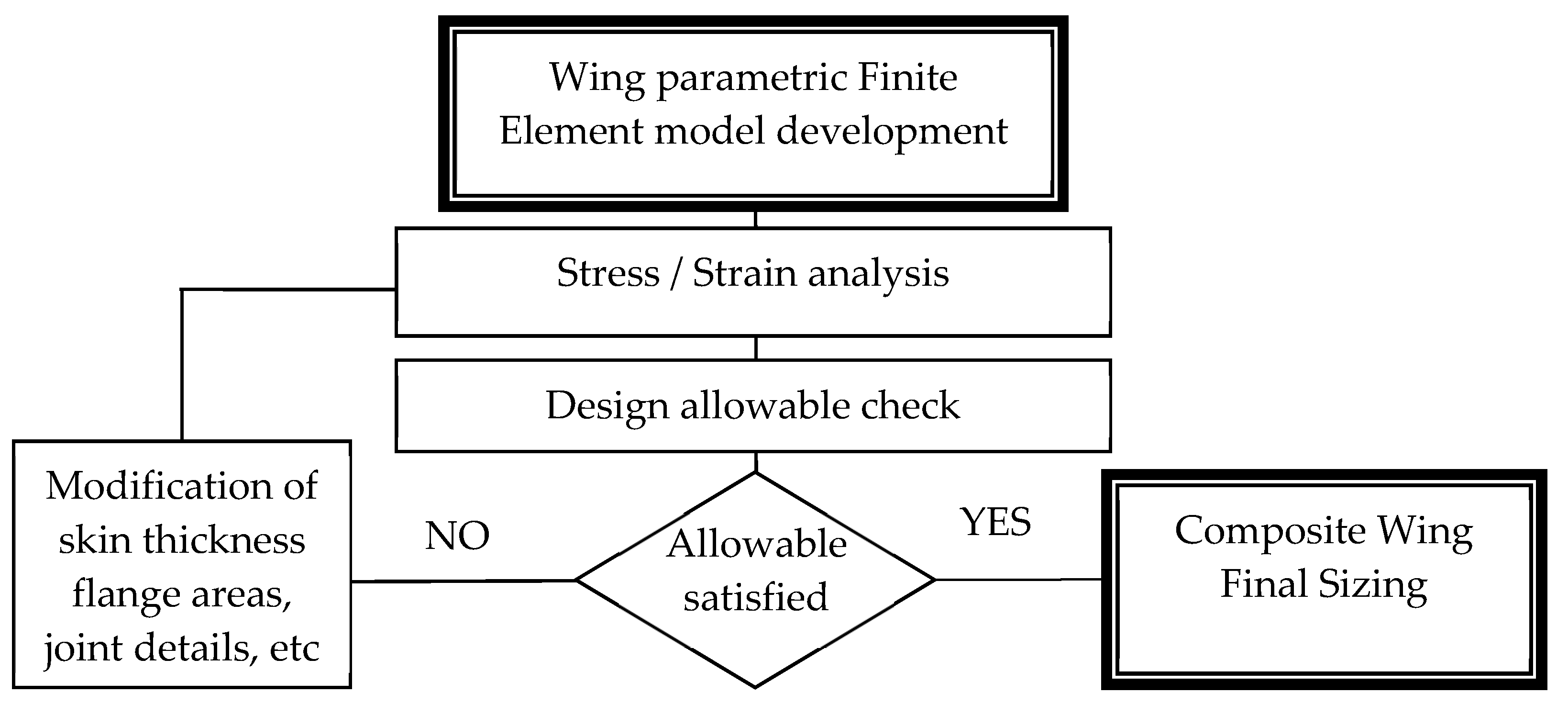
The flow chart of Figure 1 illustrates the different stages of the design optimization process, which have been followed in the present paper, for the initial sizing of an airliner composite multispar wing structure.
The parametric numerical Finite Element (FE) models of a 2-spar and a 4-spar wing configuration have been developed using ANSYS FE code [28] and they are presented in Section 2. The models are based on a 70% scaling of the basic geometrical configuration of an AIRBUS A330 aircraft. The computational models are fully parametric with respect to the main geometrical details, such that the determination of stress, strain and displacement of numerous wing structural variations is calculated as function of varying sizing parameters (i.e., thickness or area); in that way, optimization of the structural sizing is achieved. The FE results are introduced in a sizing routine, which includes an integrated set of design constraints for sizing the entire composite wing.
The design constrains, as explained in Section 3, are similar to those proposed in Herbeck’s work [24], with some modifications and additions, which mainly refer to stiffened panel buckling analysis and bearing bypass calculations. The wing numerical stress analysis, as well as the sizing routine, are iterated until all design constrains are satisfied, i.e., the corresponding Reserve Factors (RFs) must have values greater than unity.
The optimized wing designs arise by applying two different variations of the iterative optimization procedure, as further explained in Section 4. The comparison of the 2-spar and the 4-spar wing (Section 4), demonstrates that the 4-spar configuration can have a mass reduction of 1.6% to 6.3%, indicating that multispar designs can be potentially used in future airliner composite wing constructions.
2. Description of the Computational Analysis Model
A composite wingbox comprising the exact geometry of an AIRBUS A330 airliner wing, scaled at 70% of its original size, is considered for the present study. The length of the analyzed wing is 21 m (wing span of 44.95 m), with a total wing area of 94 m2. The wing geometry modeled is kept as simple as possible for both configurations, i.e., the conventional 2-spar and the 4-spar configuration. Despite the fact that the number and the position of the ribs in conjunction with the number of spars will reveal more advantages for a multispar configuration, the location of the ribs is kept constant for both configurations. The main reasons for this assumption is, firstly, the need for reducing the number of optimization parameters, secondly, to make more evident the effect and benefit of any additional spars in the wingbox and, thirdly, the fact that the final rib position in a wing structure alters as the design progresses, since the ribs are also positioned to pick up concentrated loads from landing gears, powerplants, actuators, formation of fuel tanks boundaries etc.
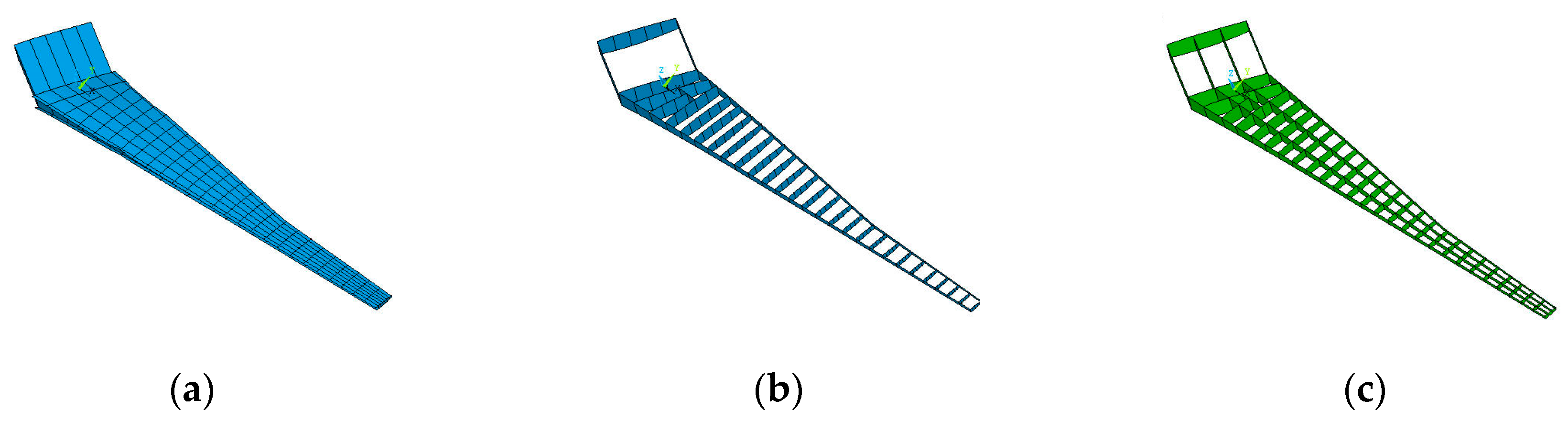
The FE models mainly comprise two or four main spars, (spar flanges and spar webs are modeled explicitly), the upper and lower skins (covers) and the ribs, as presented in Figure 2a–c. The mesh density of the FE model, is determined through a convergence study, where the vertical displacement is monitored in order to obtain an adequate mesh density for the wing structure.
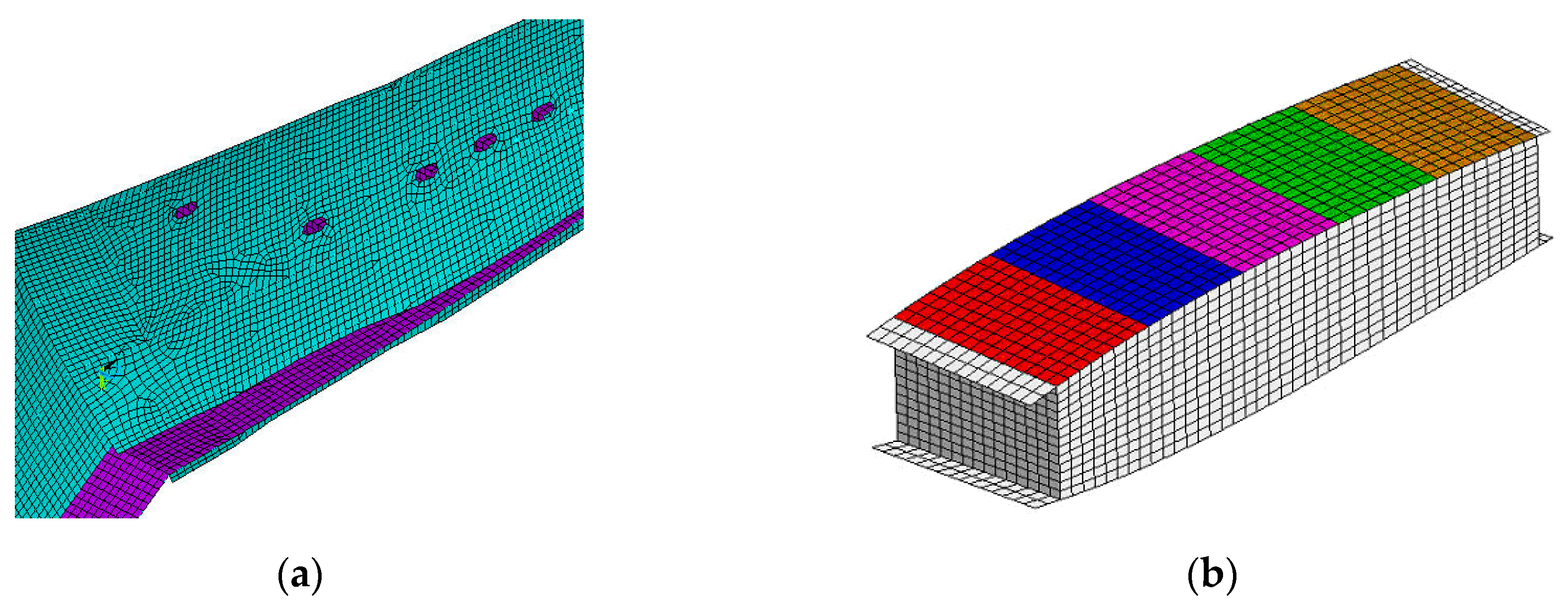
‘Shell 181’ element type of the ANSYS element library is used for the skin, rib and spar-web panels. The spar flanges are modeled using the ‘Link8’ element type, which is a 3-D spar element with uniaxial tension-compression behavior and has three degrees of freedom at each node. The entire FE model of the 2-spar and 4-spar configurations comprises approximately 40,000 and 43,000 elements, respectively. A detail of the FE model discretization in the lower side, which shows the FE mesh around the access holes area is shown in Figure 3a. It must be mentioned that all geometrical input of the model is introduced in the FE model parametrically (skin and web thickness, flange areas, bolt-hole dimensions, etc.), in order to enable variations of these parameters during the optimization procedure. Each skin panel is divided to five areas, at each of which a different thickness value may be assigned, i.e., the skin panel thickness is assumed to vary chordwise to allow weight reduction, as shown in Figure 3b. The FE model’s boundary conditions comprise fixing of all degrees of freedom in the wing root.
The material system is not a design variable in the current study. The apparent material properties of the composite lay-up applied are achieved using the Classical Lamination Theory; for both spars and ribs, the apparent elasticity modulus values are E11 = E22 = 51,953 MPa, shear modulus is G12 = 25,772 MPa and Poisson’s ratio is ν12 = 0.398; in a similar way, the respective values for the covers are E11 = 75,026 MPa, E22 = 30,335 MPa, G12 = 15,573 MPa and ν12 = 0.4366.
As the present study aims to a preliminary comparison of 2- and 4-spar wings, only the most important and critical wing loading scenario has been selected for the analysis; it comprises the aerodynamic lift and drag pressures, as well as the weight of the powerplant. All secondary loading conditions, such as landing gear loads, secondary aerodynamic loads, etc. are ignored. The above-described FE models are used to perform a linear static analysis with the use of ANSYS FE solver, from which the stresses, strains and displacements all over the wing structure are calculated.
3. Composite Wing Design Allowable
In order to perform an initial structural sizing of the wing components, the obtained static analysis results are compared to the respective allowable values, in order to check if the members’ sizing fulfil the design constraints. All structural elements of the wing, i.e., spar flanges, spar webs, skin panels and ribs are checked for satisfying the strain allowable, which ensures that no material failure will occur. In order to achieve a conservative design, the strain allowable of the current material system is set to 6000 μ for tension, −6000 μ for compression and 7000 μ for shear loading. The strain allowables are set to have these values after following AIRBUS-UK guidelines, so that certain damage tolerance principles are met.
Apart from the aforementioned strain allowable, other specific design constrains should be fulfilled. The upper skin panels, which are under compression loading due to the wing bending arising from the aerodynamic lift load, are additionally sized and verified with respect to buckling under compression, shear, and compression–shear interaction. The spar webs are additionally sized according to buckling under shear, bending and shear–bending interaction. Finally, a bearing bypass analysis is performed for the flange-web and flange-skin connection areas.
Wing ribs are additionally sized according to Brazier loading, i.e., rib crashing due to wing bending. The rib number and sizing does not affect significantly the total mass of the wing, as their total mass is less than 10% of the total wing mass; considering also the reasons mentioned in Section 2, the rib number is kept constant for both 2- and 4-spar layouts.
The implementation of the various design constrains for each structural element of the composite wing is described in detail hereafter.
3.1. Upper and Lower Skin Panels
It is well known that the upper cover of a wing is subjected to compressive and shear loads, which may lead to panel buckling. For this reason, the upper wing panels are additionally sized with respect to compressive and shear bucking, as well as to their interaction.
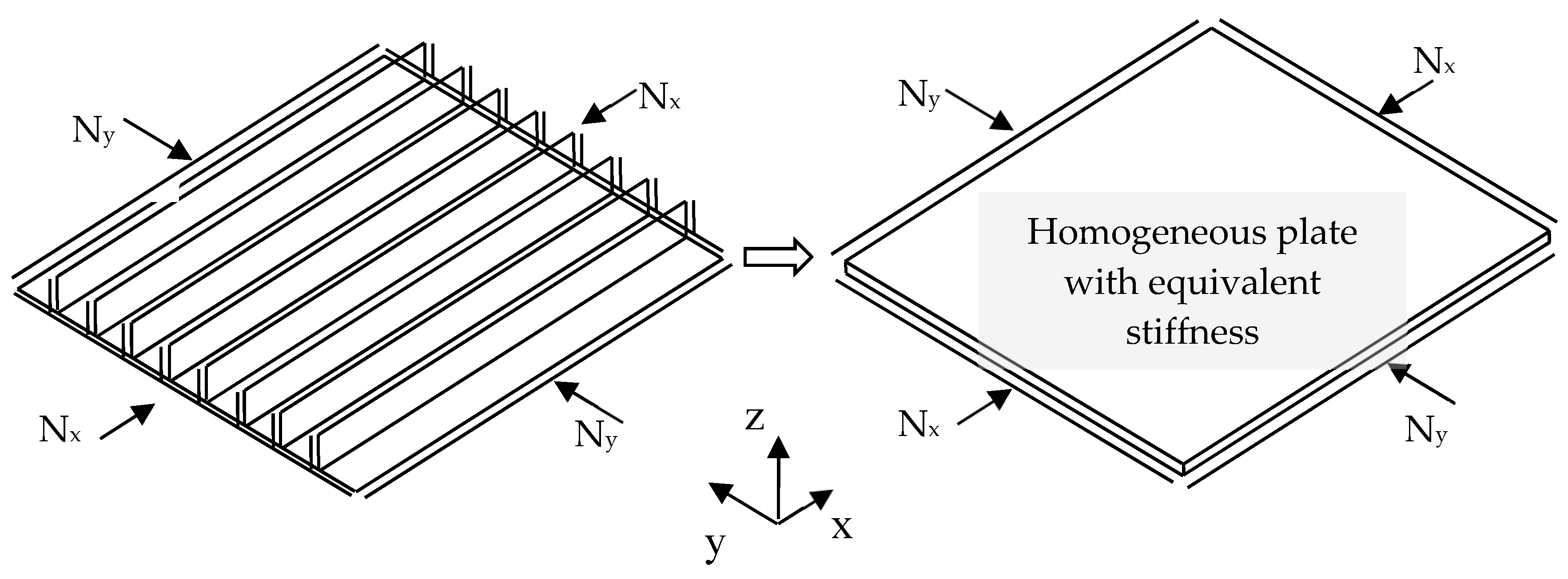
Determination of the critical buckling load of stiffened panels requires modelling of the different, complex stiffener geometry, as well as the skin stiffener interface. However, in the phase of initial and preliminary design, modelling of the stiffener geometry and its connection to the skin would result to a large-scale computational model, requiring significantly increased model development and solution effort. Furthermore, changing the design parameters and performing iterations with such a large-scale numerical model is rather impractical. Thus, to simplify the wing’s FE model, the stiffeners are not included in the panel’s FE model in a discrete way, but their stiffness is smeared into the entire panel geometry, as shown in Figure 4, in a way that their effect in buckling response is efficiently considered. According to AIRBUS-UK guidelines, it is assumed during the stiffness smearing process that the stiffeners are blade shaped with a pitch of 200 mm, which is rather typical for such aircraft wing size. Consequently, the calculation of the critical buckling load of stiffened composite panels can be performed using unstiffened panel analytical formulations [29,30,31,32].
It is also worth mentioning that, during the preliminary design phase for the buckling analysis of the panels, simply supported boundary conditions are assumed for all of their edges. This is a common assumption for this design phase, so that a relatively conservative member sizing can be obtained, as well as for simplicity reasons. In reality and in full-scale experimental tests though, the boundary conditions of the panels are elastically restrained, hence, simply supported panels are meaningless to be experimentally tested in later stages of the design. Consequently, the validation of the proposed buckling solution, which refers to simply supported panels, is obtained with the use of FE methods. Furthermore, the methodology is revised by AIRBUS-UK for its applicability. Of course, during the experimental study of the structure, where large scale components are tested, the modelling approach differentiates with the one presented hereafter. For completeness purposes, representative experimental studies are also mentioned for large scale aircraft structures [33,34,35] and for rotorcrafts [36,37].
In the present analysis, the critical buckling compressive load is calculated using the analytical solution of Equation (1) [31];
Equations (1) and (2), , are the components of the equivalent bending stiffness matrix. The equivalent bending stiffness matrix yields using an energy approach. In more detail, by equating the strain energy and the work done by the compressive forces of the stiffened panel with the respective energy of an equivalent homogeneous panel (no stiffeners), the equivalent bending stiffness terms can be calculated. Furthermore, in Equations (1) and (2), is the length of the unloaded edge of the panel and is the panel’s aspect ratio. , are the uniform distributed load applied to the panel’s edges as shown in Figure 4. , are the number of buckling half waves and their values are determined to result the minimum critical buckling load .
At each design optimization step, the skin panels may fulfil or not fulfil the buckling or the strain allowable. In either case, the panel skin thickness should be properly resized locally before a consequent iterative solution of the entire structural model is executed. The element thickness should be suitably increased in case the panel load is higher compared to the critical buckling load; on the contrary, it must be decreased in cases that the RF is much higher than unity, such that in the subsequent iterations the RF approaches unity. In the present optimization procedure, the introduced resizing rules distinguish between the possible failure types. For the case of buckling constraint, panel thickness recalculation () follows the rule:
Equation (3) arises from Equations (4) and (5), which express the RFs of two subsequent iterations () and (). The RF of the iteration is and is calculated as a function of the applied load and panel thickness , as:
Similarly the RF of the sequential iteration () is given by the first part of Equation (5).
Equation (3) yields from the substitution of Equation (4) to Equation (5) and solving with respect to panel thickness . The iterative procedure is performed until an optimum sizing is achieved, which apparently is succeeded when a RF of one () is achieved.
The critical shear buckling load of the spar webs and the upper skin panels is estimated by Equation (6), [32]; the analytical buckling solutions are valid for long panels loaded in shear:
In Equation (6), and b is the lateral dimension of the plate.
Finally, to avoid panel buckling due to interaction of compression and shear loading, the individual buckling for compression and shear (Equations (7) and (8)) are combined according to Equation (9) [38] as follows:
In Equations (7)–(9), and are the RF for compression and shear buckling, respectively.
Buckling is not an applicable sizing criterion for the lower skin, simply because it is basically loaded in tension. Therefore, the axial strain allowable of the panels governs their sizing. As already mentioned, the allowable tensile strain level used is 4500 μ.
3.2. Wing Main Spar
The investigated wing designs comprise 2- and 4-main spar layouts. Each spar consists of the upper and lower spar flanges, which are connected by the spar web. The main driving factor for the spar web’s sizing is buckling under shear loading, which is calculated by Equation (6). However, in-plane bending buckling and the interaction of shear and in-plane bending buckling are also considered. For in-plane bending buckling, a closed form analytical solution is proposed [39] as given in Equation (10).
Where in Equation (10),
The above buckling formulae for shear and in-plane bending buckling are limited to infinitely simply supported long plates, a requirement which is fulfilled in the case of the long spar webs. The interaction of shear and in-plane bending buckling is treated using the RF approach of Equations (7)–(9) of Section 1 properly modified.
3.3. Bolted and Riveted Joint Areas
3.3.1. Bearing Bypass Analysis of the Joint Areas
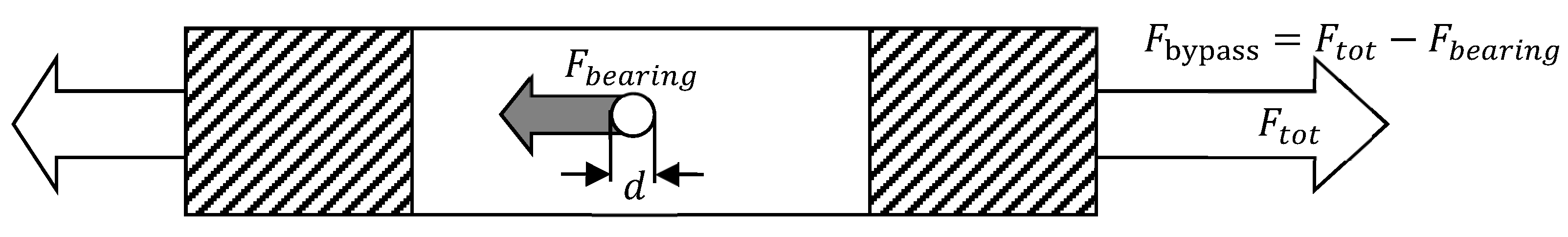
The upper and lower skins are bolted to the spar flanges, but even the best fastened joints in composite materials can still impose a loss in strength of about half the basic material allowable [40]. In general, fastener holes are subjected to the combined effects of bearing loads () and loads that bypass the hole (), as illustrated in Figure 5. The ratio of bearing to bypass load depends on the stiffness of the joint configuration. As the joint is loaded by , the bearing bypass ratio remains nearly constant until joint damage develops. Therefore, the joint area of the spar flanges to the skins should be considered for bearing or net-section failures [41,42,43].
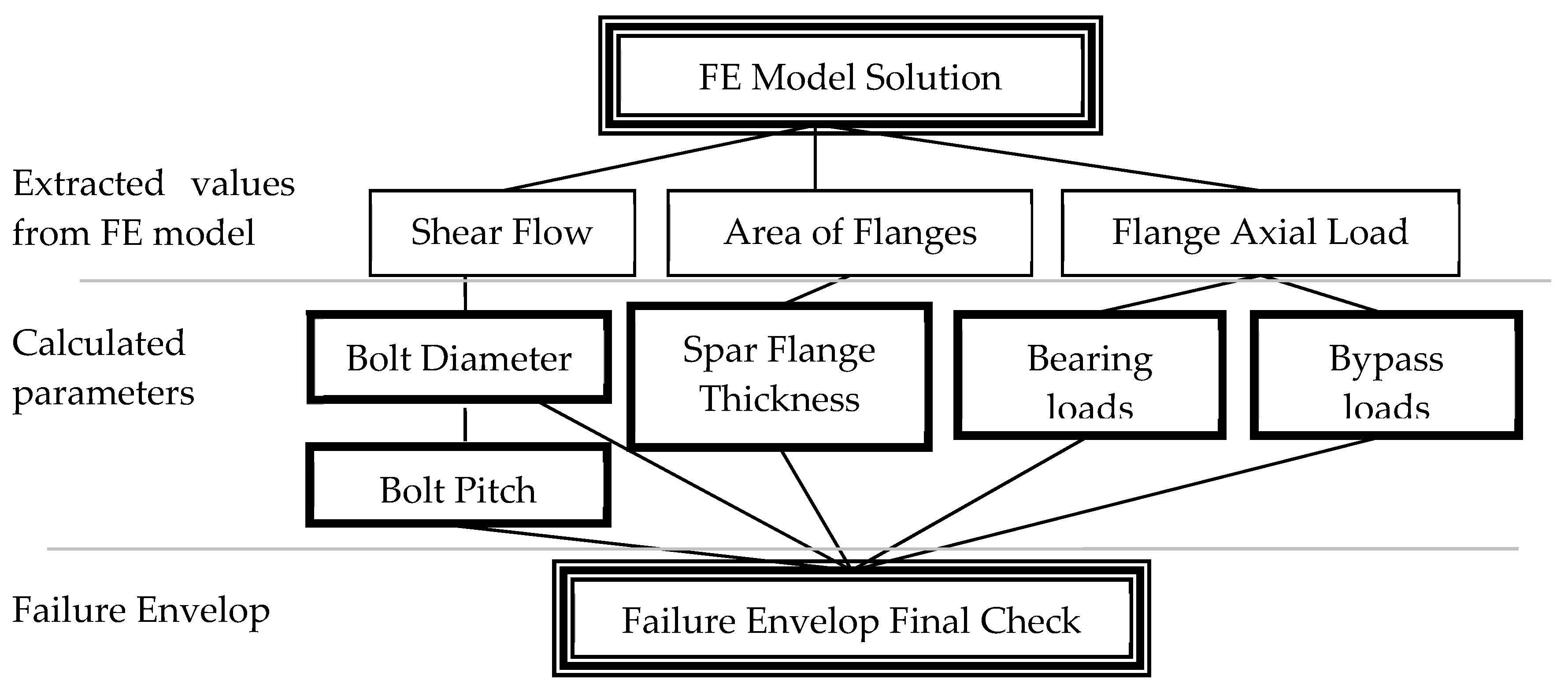
The bearing bypass analysis is the final constrain considered in the present design. The important geometric characteristics of the joint area are bolt diameter (), bolt pitch () and spar flange thickness (). The joint bearing and bypass loads, required as input for the bearing bypass analysis, are extracted from the FE model solution. In parallel, experimentally obtained failure envelopes are constructed based on joint geometrical and material data. It is consequently checked if the applied bearing and bypass loads satisfy the strength requirements. The extracted values from the FE model, as well as the calculated parameters for plotting the final failure envelope, are illustrated in the flow-chart of Figure 6. The details of the process implementation in the case of the current composite wing joints are described in the next paragraphs.
3.3.2. Geometrical Configuration of the Joint
A double row of bolts in the spanwise direction is considered for both wing configurations. The complete determination of the joint geometrical configuration requires definition of the bolt diameter (), bolt pitch and the spar flange thickness (). The bolts are equally spaced with a pitch of , following bolting empirical guidelines, which ensure that unreasonable failures will be avoided. The bolt diameters are allowed to vary in the spanwise direction.
The bolt diameter is calculated according to the inequality of Equation (11). For the present wing design, titanium bolts are selected with an allowable shear strength value of 662 MPa.
In Equation (11), the Bolt Load for a double row of bolts is calculated with the use of Equation (12).
In Equation (12), are the extracted spar web shear flow values, as calculated from the FE model solution.
3.3.3. Bearing Bypass Loading
For a joint configuration with specific bolt diameter, bolt pitch and spar flange thickness, the respective bearing and bypass loads can be calculated as follows:
In Equation (14), the values for parameter are extracted from the FE model solution by considering the section bounded by the upper and lower flanges, which lies between two sequential ribs.
3.3.4. Failure Envelope
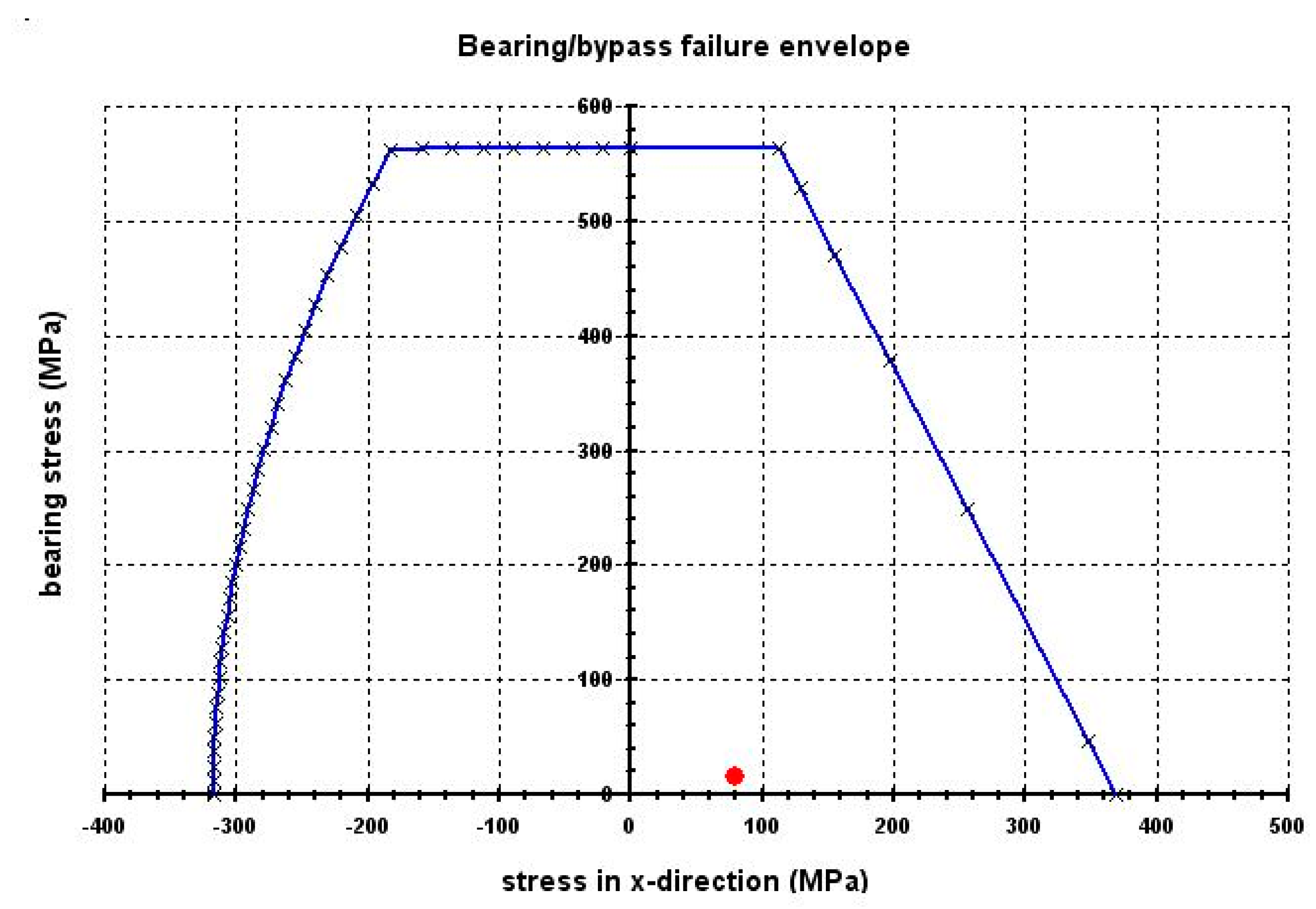
Failure envelopes covering all possible failure modes of a bolted joint, i.e., tension, cleavage, shear and bearing have the typical form of Figure 7. Such failure envelopes are constructed by experimentally testing different geometrical configurations of bolted joints with different material types and lay-ups. The bearing bypass failure envelope, which corresponds to the geometry, material system and lamination of the joint as defined in each iteration, is examined in order to examine if the applied bearing bypass load combination (indicated by the red dot plotted in Figure 7) falls within the respective failure envelope. Apparently, when the bearing bypass load combination falls inside the envelope, no joint failure is expected, while when the dot lies outside the failure envelope a failure is predicted, thus another re-sizing iteration should be performed.
The sizing of spar flanges additionally requires that the values of flange thickness and bolt diameter , satisfy the condition of Equation (15), in order to avoid bolt intrusion to the laminated flange.
The entire bearing bypass sizing procedure described above is programmed in Visual Basic for Applications (VBA) of Excel and hence the procedure can be repeated iteratively until a safe design is obtained for each joint area.
4. Comparison between 2- and 4-Spar Configurations
A post processing code has been developed as an ANSYS macro-routine in order to perform an automated allowable check of all the components of the wing model. The macro-routine extracts geometric data and strain/stress results, derives magnitudes of interest out of them using analytical functions and compares them with the pre-set limits, i.e., maximum allowable strain levels, critical buckling loads, bearing bypass limits, etc. Several iterations are required until all design rules are satisfied and the final sizing that eventually provides the lightest structure of each configuration arises.
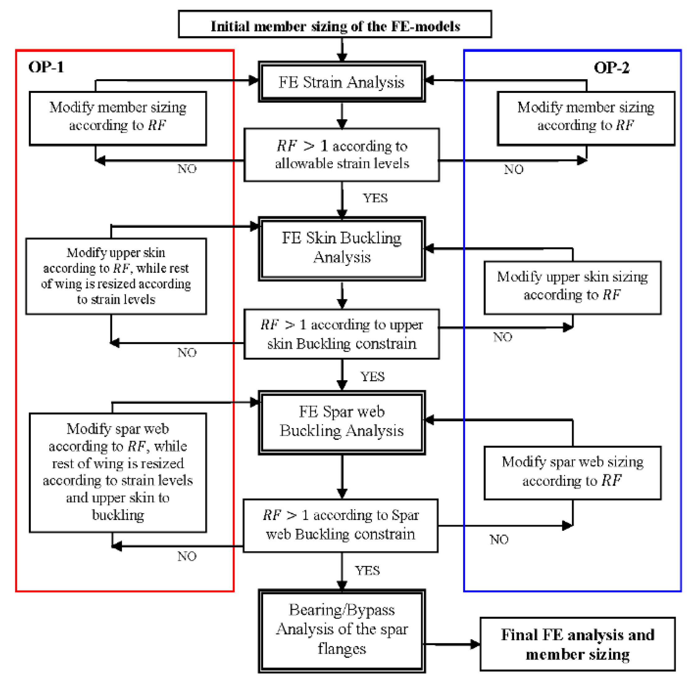
Two different variations of the optimization process have been trailed in the present study; both variations consist of the same four steps, specifically: (a) sizing of the entire wing, such that all its components satisfy the pre-set strain levels; (b) sizing of the upper skin panels, such that compression buckling constraints are satisfied; (c) sizing of the webs according to shear and bending buckling criteria, and (d) bearing bypass analysis for the bolted joint areas. In the first variation of the optimization procedure (referred hereafter as OP-1), at each optimization step, the structural members are sized according to one constraint and consequently all other structural members are resized with respect to all other constraints. In the second variation of the optimization procedure (referred hereafter as OP-2), no resizing of already sized members is performed, when other members are checked for the additional constraints.
The flow chart of Figure 8 illustrates the details of the different stages of the optimization process followed, highlighting the differences between the two iterative schemes.
5. Results and Discussions
A comparison between 2- and 4-spar wing designs is performed. In Table 1, a detailed mass breakdown in (kg) for both configurations is presented. Comparing the results of Table 1, the 4-spar arrangement appears to be relatively lighter compared to the conventional 2-spar design.
It can also be observed from Table 1 that the 4-spar arrangement appears to be lighter than the 2-spar by approximately 1.3% (38 kg) and 6.3% (198 kg), when OP-1 and OP-2 are applied, respectively.
Another important remark refers to the lateral wing tip displacement (Uz), which has been calculated to be about 3.3 m for both models, indicating that the entire wing stiffness remains almost constant in both configurations. This can be initially explained by considering that both configurations are sized based on the same allowable strain values. This important remark is better understood if a wing cross-section is considered; it is evident that when the number of spars increases, the design optimization requires a mass movement from the skin towards the spar flanges, with a tendency to keep the overall second moment of inertia almost constant. This observation indicates that no significant mass savings can be achieved, if the sizing is based exclusively on strain allowable.
As previously mentioned, compression buckling is the driving design factor for the upper skin panels for both wing arrangements (2- and 4-spar). The fulfillment of compression buckling constraints can give advantage to a multispar configuration, due to a positive change of the panel aspect ratios, resulting to higher critical buckling loads (Equation (1)). It is found that for the case considered, the weight penalty due to buckling reaches to approximately 30% of the upper skin mass, i.e., between 500 kg and 600 kg for the conventional arrangement. On the other hand, the weight penalty required to fulfill upper cover buckling constraints of the 4-spar arrangement is only 10% of the upper skin mass. Therefore, the margin for a potential weight saving relevant to panel compression buckling is quite essential. Nevertheless, the total mass of the spars in the 4-spar arrangement is higher compared to those in the conventional configuration. The reduction of the skin mass in the 4-spar arrangement is relatively higher to the mass penalty caused by the addition of intermediate spars in the multispar configuration, which results to an overall advantage of the multispar arrangement.
The material system has not been considered as an optimization parameter in the present study. However, an important remark with respect to the selection material system for a multispar configuration is that a material system with significantly higher elastic modulus () in the principal material direction is required for the spars. It is believed that a lamination enhanced in the spanwise wing direction will withstand higher axial loads, which will result a more beneficial multispar configuration.
It is worth mentioning at this point that this parametric study is carried out in the frames of the preliminary structural design phase and its aim is to explore whether a multispar configuration has potential advantages for further analysis. The impact of a multispar configuration to the aircraft’s performance has not been considered at this stage. However, it is expected, in the multispar configuration, to have a reduced space in the wings for fuels, compared to a conventional spar arrangement that will probably result to reduced overall flight range and endurance if no further actions or considerations are taken. In the multispar configuration, the fuel space issues that will arise due to the additional spars in the wingbox, can be overcome by adopting the fuel tank scheme that is used in fighter aircrafts with multispar wing layouts. Moreover, an extended center fuel tank in the fuselage can be also foreseen to meet the flight range and endurance requirements of the aircraft.
6. Conclusions
An effective method for sizing large scale composite components, such as aircraft wings, is developed and presented in the current paper. The method is demonstrated in the preliminary design of a multispar composite wing configuration and it has been proven that the actual member sizing (spar, skin, etc.) can be obtained in a relative small time frame, even though iterations are required.
Analytical closed form solutions for predicting the critical buckling load of stiffened panels are developed with the use of a smearing approach so that the buckling solution equations can be programmed easily, within ANSYS (ANSYS Parametric Design Language) APDL, and provide instant results during an iteration loop. Moreover, empirical bolting rules for joining the skin to the spar flanges are applied and in conjunction with the derived bolted-joint failure envelopes, the sizing of all joint areas is obtained. By utilizing the bolted-joint failure envelopes the determination of the sizing of the bolts can be completed without running any joint FE analyses that will increase the computational cost and time of each iteration. Additionally, two optimization procedures (OP) are followed to obtain the final sizing solutions. OP-2 does not allow resizing of all wing members between consequent iterations of the optimization results to more conservative designs and hence has less mass saving. Moreover, for the OP-2 the required time and number of iterations, to obtain a converged solution regarding the member sizing, is less than the time required for OP-1. However, both optimization procedures require less than two hours in a standard computer (8GB RAM) to converge to the final member sizing (regardless the configuration).
The final comparison between the two optimized configurations showed that the 4-spar arrangement appears to be lighter than the conventional 2-spar wing by 1.3% (38 kg) or 6.3% (198 kg) depending on the optimization procedure followed. The lateral displacement of the wing tip is found to be approximately the same for both configurations indicating that the total stiffness of the two wing configurations remains almost constant. Compression buckling is the driving constraint for the upper skin; its fulfillment provides advantage to the multispar configuration, due to positively changing of the wing panel aspect ratios which result to higher critical buckling loads. It is believed that a more efficient multispar arrangement may be achieved by employing a material system of higher modulus of elasticity in the spar direction. Finally, apart from the reduction of wing mass, a multispar wing solution can have advantages from a manufacturing point of view if modular manufacturing techniques are considered.
Author Contributions
The conceptualization of this research was conceived by D.S. and G.L. the methodology was developed by D.S. and G.L. The numerical analyses (programming) as well as the validation of the FE models was performed by D.S. The original draft of this manuscript was prepared by D.S. and reviewed and edited by G.L. G.L. supervised the documented research and he was responsible for the project administration on behalf of the University of Patras. Finally, the authors have read and agreed to the published version of the manuscript. All authors have read and agreed to the published version of the manuscript.
Funding
This research was funded by the EU research project Advanced Low Cost Aircraft Structure “ALCAS”, grant number 516092.
Acknowledgments
The authors wish to acknowledge AIRBUS-UK for the support of this research.
Conflicts of Interest
The authors declare no conflict of interest.
References
- Cavallaro, R.; Demasi, L. Challenges, Ideas, and Innovations of Joined-Wing Configurations: A Concept from the Past, an Opportunity for the Future. Prog. Aerosp. Sci. 2016, 87, 1–93. [Google Scholar] [CrossRef]
- Bacarreza, O.; Aliabadi, M.H.; Apicella, A. Robust design and optimization of composite stiffened panels in post-buckling. Struct. Multidiscip. Optim. 2015, 51, 409–422. [Google Scholar] [CrossRef] [Green Version]
- Mulani, S.B.; Duggirala, V.; Kapania, R.K. Curvilinearly T-stiffened panel-optimization framework under multiple load cases using parallel processing. J. Aircr. 2013, 50, 1540–1554. [Google Scholar] [CrossRef]
- Mulani, S.B.; Joshi, P.; Li, J.; Kapania, R.K.; Shin, Y.S. Optimal design of unitized structures using response surface approaches. J. Aircr. 2010, 47, 1898–1906. [Google Scholar] [CrossRef]
- Locatelli, D.; Mulani, S.B.; Kapania, R.K. Parameterization of curvilinear spars and ribs for optimum wing structural design. J. Aircr. 2014, 51, 532–546. [Google Scholar] [CrossRef]
- Liu, Q.; Jrad, M.; Mulani, S.B.; Kapania, R.K. Global/local optimization of aircraft wing using parallel processing. AIAA J. 2016, 54, 3338–3348. [Google Scholar] [CrossRef]
- Locatelli, D.; Mulani, S.B.; Kapania, R.K. Wing-box weight optimization using curvilinear spars and ribs. J. Aircr. 2011, 48, 1671–1684. [Google Scholar] [CrossRef]
- Stanford, B.K.; Beran, P. Optimal structural topology of a plate-like wing for subsonic aeroelastic stability. J. Aircr. 2011, 48, 1193–1203. [Google Scholar] [CrossRef]
- Stanford, B.K.; Dunning, P.D. Optimal topology of aircraft rib and spar structures under aeroelastic loads. J. Aircr. 2015, 52, 1298–1311. [Google Scholar] [CrossRef] [Green Version]
- Bisagni, C.; Vescovini, R. Analytical formulation for local buckling and post-buckling analysis of stiffened laminated panels. Thin Walled Struct. 2009, 47, 318–334. [Google Scholar] [CrossRef]
- Kim, C.; Yoon, I.-S. The stacking sequence optimization of stiffened laminated curved panels with different loading and stiffener spacing. J. Mech. Sci. Technol. 2006, 20, 1541–1547. [Google Scholar] [CrossRef]
- McCullers, L.A.; Naberhaus, J.D. Automated structural design and analysis of advanced composite wing models. Comput. Struct. 1973, 3, 925–935. [Google Scholar] [CrossRef]
- Snell, M.B.; Barlothomew, P. The engineering optimization of hybrid composite/metallic wing boxes for buckling and strength constrain. Comput. Struct. 1987, 7, 21–58. [Google Scholar] [CrossRef]
- Rothwell, A. Multi-level optimization of aircraft shell structures. Thin Walled Struct. 1991, 11, 82–103. [Google Scholar] [CrossRef] [Green Version]
- Seresta, O.; Adams, D.B. Optimal design of composite wing structures with blended laminates. Compos. Part B Eng. 2007, 38, 469–480. [Google Scholar] [CrossRef]
- Vidanović, N.; Rašuo, B.; Kastratović, G.; Maksimović, S.; Ćurčić, D.; Samardžić, M. Aerodynamic–structural missile fin optimization. Aerosp. Sci. Technol. 2017, 65, 26–45. [Google Scholar] [CrossRef]
- Garinis, D.; Dinulovic, M.; Rasuo, B. Dynamic Analysis of Modified Composite Helicopter Blade. FME Trans. 2012, 40, 63–68. [Google Scholar]
- Dinulovic, M.; Rasuo, B.; Krstic, B. The analysis of laminate lay-up effect on the flutter speed of composite stabilizers. In Proceedings of the ICAS 2016 Congress, Daejeon, Korea, 25–30 September 2016. [Google Scholar]
- Shao, K.; Wu, Z.; Yang, C. Analysis and flexible structural modeling for oscillating wing utilizing aeroelasticity. Chin. J. Aeronaut. 2008, 21, 402–410. [Google Scholar] [CrossRef] [Green Version]
- Colson, B.; Bruyneel, M.; Grihon, S. Optimization methods for advanced design of aircraft panels: A comparison. Optim. Eng. 2010, 11, 583–596. [Google Scholar] [CrossRef]
- Komur, M.; Sonmez, M. Elastic buckling of rectangular plates under linearly varying in-plane normal load with a circular cutout. Mech. Res. Commun. 2008, 35, 361–371. [Google Scholar] [CrossRef]
- Watson, A.; Kennedy, D.; Williams, F.W. Design of structures by a splitting method. Comput. Struct. 1999, 70, 377–386. [Google Scholar] [CrossRef] [Green Version]
- Aston, G.; Williams, F.W. Simplified methods for the buckling analysis of composite multi-spar wing boxes. Comput. Struct. 1994, 28, 215–223. [Google Scholar] [CrossRef]
- Herbeck, L.; Wilmes, H. Design rules for a CFRP composite wing. In Proceedings of the ICAS 2002 Congress, Toronto, ON, Canada, 8–13 September 2002. [Google Scholar]
- Chintapalli, S.; Elsayed, M. The development of a preliminary structural design optimization method of an aircraft wing-box. Aerosp. Sci. Technol. 2010, 14, 188–198. [Google Scholar] [CrossRef]
- Stamatelos, D.G.; Labeas, G.N. Investigation on a multi-spar composite wing. Proc. Inst. Mech. Eng. Part G J. Aerosp. Eng. 2011, 225, 88. [Google Scholar] [CrossRef]
- Moors, G.; Kassapoglou, C.; de Almeida, S.F.M. Weight trades in the design of a composite wing box: Effect of various design choices. CEAS Aeronaut. J. 2019, 10, 403–417. [Google Scholar] [CrossRef] [Green Version]
- ANSYS User’s Manual Version 10.0; Swanson Analysis System, Inc.: Canonsburg, PA, USA, 2004.
- Whitney, J.M. Structural Analysis of Laminated Anisotropic Plates; Technocomic Publishing Company: Lancaster, UK, 1987; Chapter 5; ISBN 87762-518-2. [Google Scholar]
- Grayley, M.E. Buckling of Rectangular Specially Orthotropic Plates; ESDU International PLC: London, UK, 1995. [Google Scholar]
- Narita, Y.; Leissa, W. Buckling studies for simply supported symmetrically laminated rectangular plates. Int. J. Mech. Sci. 1990, 32, 909–924. [Google Scholar] [CrossRef]
- Bruns-Treml, M. Program AESOP, Stability-Modulus; AIRBUS: Toulouse, France, 2001. [Google Scholar]
- Fahnestock, L.; Ricles, J.; Sause, R. Experimental Evaluation of a Large-Scale Buckling-Restrained Braced Frame. J. Struct. Eng. 2007, 133, 415–425. [Google Scholar] [CrossRef]
- Singer, J.; Arbocz, J.; Weller, T. Buckling Experiments, Shells, Built-Up Structures, Composites and Additional Topics; John Wiley & Sons: Hoboken, NJ, USA, 2002; Volume 2. [Google Scholar]
- Featherston, C.A. Experimental buckling of a simple aerofoil under combined shear and in-plane bending. Proc. Inst. Mech. Eng. C J. Mech. Eng. Sci. 2004, 218, 155–172. [Google Scholar] [CrossRef] [Green Version]
- Rasuo, B. Experimental Techniques for Evaluation of Fatigue Characteristics of Laminated Constructions from Composite Materials: Full-Scale Testing of the Helicopter Rotor Blades. J. Test. Eval. 2011, 39, 237–242. [Google Scholar] [CrossRef]
- Rasuo, B. Experimental Study of the Structural Damping of Composite Helicopter Blades with Different Cores. Plast. Rubber Compos. 2010, 39, 1–5. [Google Scholar] [CrossRef]
- Bruhn, E.F. Analysis and Design of Flight Vehicles Structures; Jacobs Pub: Austin, TX, USA, 1973; Chapter 5; ISBN 0961523409. [Google Scholar]
- Gates, T.; Odegrad, G.M.; Nementh, M.P.; Frankland, S.V. Predicting the influence of Nano-scale material structure on the in-plane buckling of orthotropic plates. In Proceedings of the 45th AIAA/ASME/ASCE/AHS/ASC Structures, Structural Dynamics and Materials Conference, Palm Springs, CA, USA, 19–22 April 2004; pp. 1024–1038. [Google Scholar]
- Niu, M.C.Y. Composite Airframe Structures. Practical Design Information and Data, 2nd ed.; Conmilit Press Ltd.: Hong Kong, China, 1992. [Google Scholar]
- Crews, J.H.; Naik, R.A. Combined bearing and bypass loading on a graphite-epoxy laminate. Compos. Struct. 1986, 6, 21–40. [Google Scholar] [CrossRef] [Green Version]
- Ireman, T.; Eriksson, T.R.I. On damage development in mechanically fastened composite laminates. Compos. Struct. 2000, 49, 151–171. [Google Scholar] [CrossRef]
- Dano, M.L.; Gendron, G.; Picard, A. Stress and failure analysis of mechanically fastened joints in composite laminates. Compos. Struct. 2000, 50, 287–296. [Google Scholar] [CrossRef]
Figure 1.
Flow chart of the multispar composite wing design process.

Figure 2.
(a) Outer geometry of the wing; (b) inner 2-spar wing structure; (c) inner 4-spar wing structure.
Figure 2.
(a) Outer geometry of the wing; (b) inner 2-spar wing structure; (c) inner 4-spar wing structure.

Figure 3.
(a) Discretization of lower skin in the area of access holes; (b) chordwise panel thickness variation (right).
Figure 3.
(a) Discretization of lower skin in the area of access holes; (b) chordwise panel thickness variation (right).

Figure 4.
Homogenization of a stiffened panel by smearing stiffeners.

Figure 5.
Bolted joint bearing bypass load transfer schematically represented.

Figure 6.
Flow chart of the bearing bypass bolted joint analysis.

Figure 7.
Bearing bypass failure envelope.

Figure 8.
Detailed flow chart of the two variations of the optimization process applied to both composite wing configurations.
Figure 8.
Detailed flow chart of the two variations of the optimization process applied to both composite wing configurations.


Table 1.
Detailed final mass breakdown of the 2-spar and the 4-spar composite wing structural configurations.
Table 1.
Detailed final mass breakdown of the 2-spar and the 4-spar composite wing structural configurations.
| Optimization Procedure 1 | Optimization Procedure 2 | |||
|---|---|---|---|---|
| Wing Component | 2-Spar Arrangement | 4-Spar Arrangement | 2-Spar Arrangement | 4-Spar Arrangement |
| Upper Skin | 1405 | 956 | 1474 | 993 |
| Lower Skin | 776 | 656 | 862 | 749 |
| Front Spar Web | 154 | 123 | 156 | 119 |
| Front Spar Flange | 84 | 55 | 175 | 92 |
| 2nd Spar Web | - | 158 | - | 160 |
| 2nd Spar Flange | - | 213 | - | 160 |
| 3rd Spar Web | - | 133 | - | 132 |
| 3rd Spar Flange | - | 166 | - | 152 |
| Rear Spar Web | 99 | 75 | 99 | 78 |
| Rear Spar Flange | 106 | 53 | 131 | 71 |
| Ribs | 213 | 210 | 241 | 233 |
| Total Wing Weight (kg) | 2837 | 2798 | 3138 | 2939 |
© 2020 by the authors. Licensee MDPI, Basel, Switzerland. This article is an open access article distributed under the terms and conditions of the Creative Commons Attribution (CC BY) license (http://creativecommons.org/licenses/by/4.0/).
Share and Cite
MDPI and ACS Style
Stamatelos, D.; Labeas, G. Towards the Design of a Multispar Composite Wing. Computation 2020, 8, 24. https://0-doi-org.brum.beds.ac.uk/10.3390/computation8020024
AMA Style
Stamatelos D, Labeas G. Towards the Design of a Multispar Composite Wing. Computation. 2020; 8(2):24. https://0-doi-org.brum.beds.ac.uk/10.3390/computation8020024
Chicago/Turabian StyleStamatelos, Dimitriοs, and George Labeas. 2020. "Towards the Design of a Multispar Composite Wing" Computation 8, no. 2: 24. https://0-doi-org.brum.beds.ac.uk/10.3390/computation8020024
Note that from the first issue of 2016, this journal uses article numbers instead of page numbers. See further details here.