1. Introduction
Nowadays, owing to the increase of demands for high-quality industrial products, along with paramount consideration for lowering cost and weight, induce many attempts in the design and development of elastic systems. Friction clutches constitute vital components in many applications such as vehicles, machines of productions, etc. A popular known application of a clutch in an automotive vehicle is used to connect and disconnect the engine with the gear box. An accurate and reliable stress analysis of the clutch system parts is one of the major concerns to the mechanical design engineers to ensure reliability and long-life operation. However, an accurate computation of thermal stresses and contact pressure is very difficult to obtain due to many complexities involved in this process such as the geometry of the clutch system, variation of material properties, coefficient of friction, surface roughness, etc. The high temperatures will appear on the contacting surfaces of the clutch’s elements, which lead to generate of high thermal stresses. These thermal stresses are responsible for several disadvantages such as surface cracks, permanent distortions, etc. Finally, in some cases these disadvantages may lead the surfaces of contact to fail before the expected lifetime.
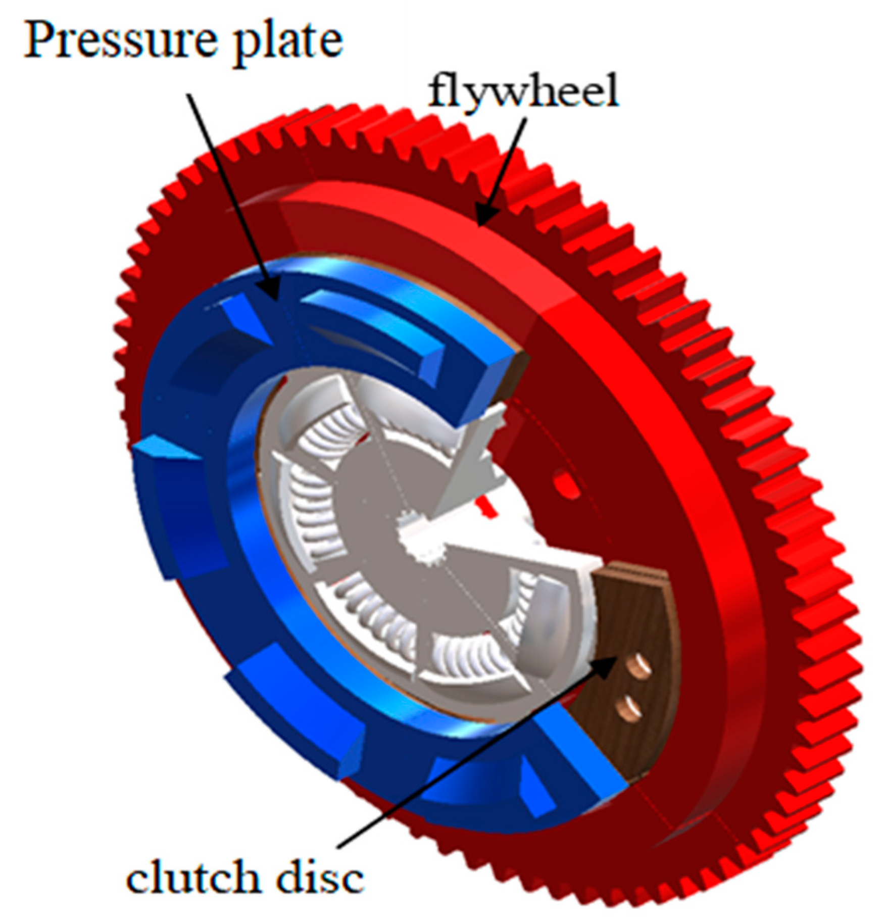
Figure 1 illustrates the main parts of the dry clutch system (clutch disc, pressure plate, and flywheel) that are responsible to transfer the power from the driving part to the driven part.
After studying the available literature that related to the numerical solutions of the thermal problem of dry friction clutches through the sliding/heating phase, it was found that the vast majority of researchers used two-dimensional numerical models (axisymmetric models) to simulate the thermal problem of the clutch system to obtain the thermal behaviour and performance during the thermal stage [
1,
2,
3,
4,
5,
6,
7,
8,
9]. Meanwhile, there are a very limited number of studies that developed three-dimensional numerical models, where most of these models failed to represent all the complexities of the geometry of a frictional clutch and they were approximated models. However, they obtained acceptable results compared with the analytical and experimental solutions.
On the other hand, a limited number of researchers resorted to an analytical solution to find the temperatures and thermal stresses of the automotive friction clutches and brakes based on some assumptions in an attempt to reduce the complications of the thermal problem of the clutch. One of these hypotheses is assuming that the variation in temperature is in one dimension only and neglecting many other important factors such as convection, surface roughness, distribution of contact pressure, etc. [
10,
11,
12,
13,
14,
15,
16,
17,
18,
19,
20,
21]. The purpose of all these hypotheses is to obtain an analytical solution by avoiding the solutions for 2D or 3D models.
Chao et al. [
22] applied the finite element method to study the thermal behaviour of the dry dual clutch under different load conditions. A 3D model was created using CATIA software and then the ABAQUS software was used for the numerical analysis. Their results presented the temperature and the thermal stresses during the sliding time. They applied the thermal load based on the basic approach, that adopted the heat partition factor. Its mean was to find the solution of each element of the clutch system separately. Using the same approach, Bao et al. [
23] investigated the effect of grooves in the frictional clutch disc in order to study the change in the thermal behaviour due to the shape of the groove. Three types of grooves were used, which were a two-way parallel groove, a three-way parallel groove, and a waffle groove. They found that the the waffle groove shape is the most optimal one because of the minimum level of heat generated.
Zhang et al. [
24] presented a 2D numerical model of the wet clutch system. It was included in the numerical model the effect of the viscous shear, asperity friction and convection effect. The Runge–Kutta method was applied to find the solution of the frictional thermal model. They investigated the influence of some significant factors such as material parameters, applied pressure, initial angular velocity, friction lining permeability, and surface roughness. They found that the surface roughness and the material properties have a great effect on the surface temperature.
The researchers were faced with challenges of cost and complexities of the clutch system when they resorted to the experimental work. Furthermore, the time issues to design, perform and validate a new test rig. Therefore, it was concluded that the most appropriate approach among the solutions which are currently available based on the reasons mentioned above to find the solution of the frictional thermal problem of automotive clutches and brakes is the finite element method. During the last years, the researchers overcame great challenges to build an advanced mathematical model, taking into account many important factors that interact during realistic operating conditions.
The main objective of this work is to present a new developed three-dimensional FE model of a dry friction clutch and adopt it to compute the distributions of temperature during the slipping period (single engagement). This model is considered the most accurate model that is available until now, based on the available literature. Where all shape complexities were taken into consideration for all elements of the clutch system (
Figure 1,
Figure 2 and
Figure 3). Furthermore, it was derived a new mathematical model to the clutch system from scratch to obtain the thermal analytical solution in order to simulate the thermal problem during the sliding time. The comparisons were made between the results of two solutions, where the maximum difference between them is not exceeded 1%.
2. Formulation of Thermal Problem
During the heating phase of the clutch’s working cycle, slipping will occur between driving and driven parts. As result, high temperature will appear on the contacting surfaces of the flywheel, the clutch disc and the pressure plate. Where, it was supposed that all amounts of heat energy were all generated from all kinetic energy, which means no losses. Thus, the frictional heat generated at any time between the surfaces of contacting elements is [
9],
where,
ts is the slipping time,
ωs is the angular sliding velocity (rad/s),
p is the contact pressure (N/m
2),
is coefficient of friction and
r is the disc radius (m). Assuming that the angular slip rate decreases as following from,
ωo: the preliminary angular sliding velocity (
ts = 0). Therefore, the final equation for the rate of heat generated between the contacting elements is,
All the parameters of the clutch’s elements have been indexed with (c) for the friction material, (cu) for the axial cushion, (p) for the pressure plate and (f) for the flywheel. The high frictional heat will be generated as a result of the sliding velocity with the existing of applied pressure between the contacting surfaces, where the frictional material has high roughness. The heat will dissipate between the elements of the clutch system by conduction and to the working environmental by convection. Hence, that the slipping time is too short (less than 1 s), therefore it can be ignored the influence of radiation in the numerical analysis with no significant effect on the accuracy of results.
It can be considered that the creating of the 3D geometry of the main parts of the clutch system that including in the numerical solution is the fundamental stage. Solidworks 2020 was used to create the model of the clutch system based on the realistic dimensions. After that, a numerical approach was developed to simulate the thermal problem of the clutch system using Ansys (workbench) 2021 in order to obtain the complete solution of the problem. It was assumed the temperature at the initial time of sliding was,
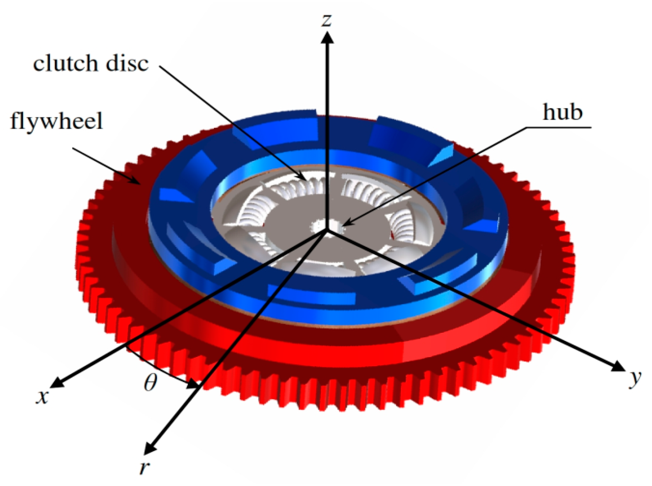
Next step, the heat conduction equation was applied for the main elements of the frictional clutch as shown in
Figure 2,
where,
α is the thermal diffusivity (
α =
k/
ρ c).
r,
θ and
z are the cylindrical coordinates. It was taken into consideration the convection effect on the surfaces that exposed to the working environment during the sliding time.
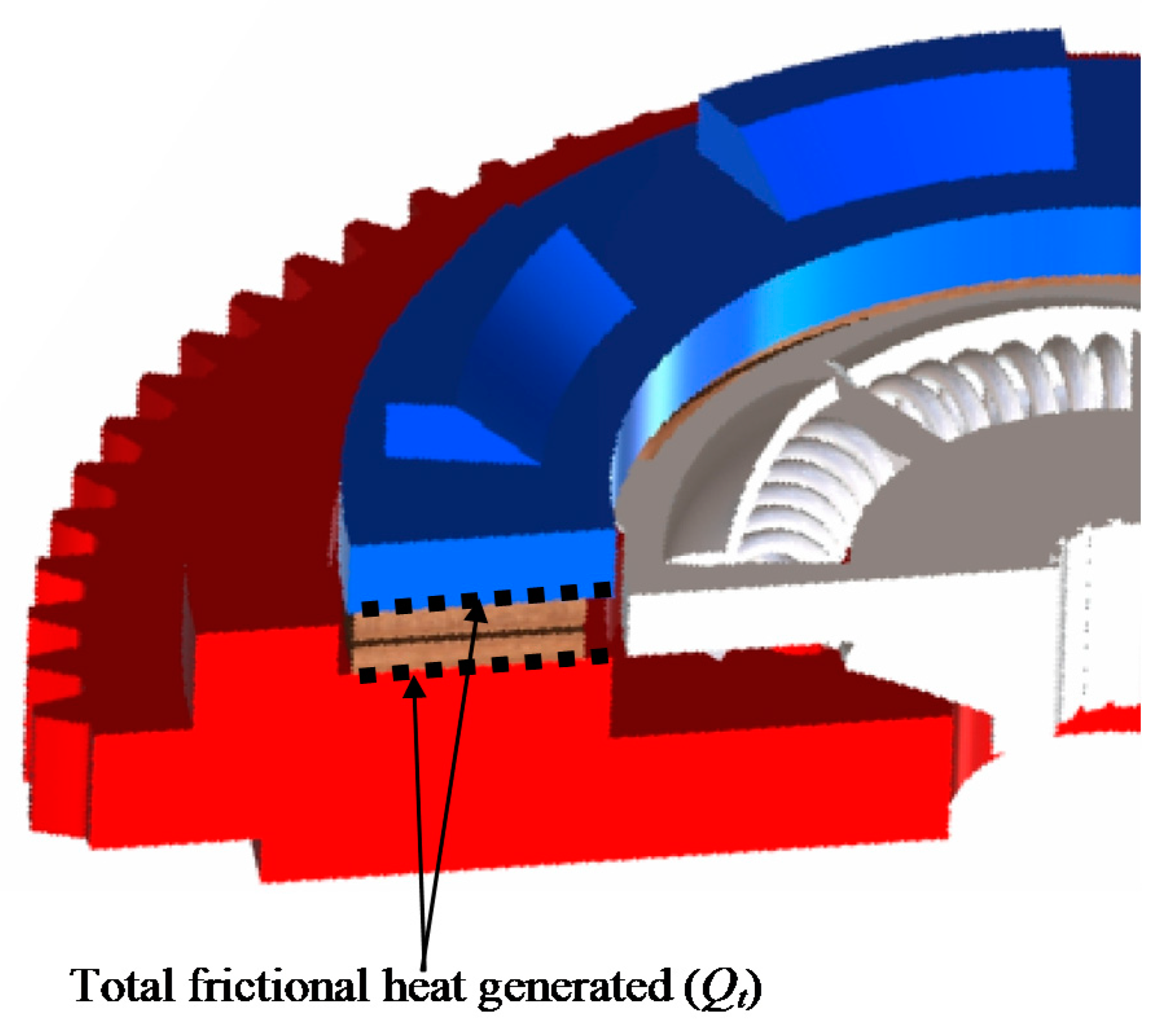
Figure 3 illustrates the thermal load that generates between the surfaces of contacting elements.
3. Finite Element Analysis
The main steps of the numerical approach (FE) will present in this section, including the hypotheses required to obtain the numerical solution. The thermal problem in the friction clutch system should be represented as a transient problem due to the large variation of temperature during a very short time. The solution of the thermal problem of the clutch system based on the finite element method can be written as [
25],
where, [
C] and [
K] are the matrices of specific heat and conductivity. {
T}, {
Ṫ} and {
Ṫ} are the vectors of the temperatures of nodes, derivative of temperature with respect to time and thermal load, respectively. One of the significant factors affect the accuracy for finite element results is the selection mesh of the FE model. Where, it was made the Mesh Independence Study was conducted in order to obtain the most suitable mesh to obtain highly accurate results of temperatures. The Crank–Nicolson technique was applied to the scheme. It was assumed that friction clutch works under dry conditions and the heating phase is very short. The boundary and initial conditions of the elements for dry friction clutch system (single disc) are given as follows (
Figure 2 and
Figure 3):
Axial cushion: the condition at the outer disc radius,
and at the inner disc radius is,
where
Ta is the ambient surrounding temperature and
h is the convection heat transfer coefficient.
Friction clutch disc: the condition at the inner disc radius; there is a convection,
and at the outer disc radius is,
the frictional heat generated on the contact surfaces of clutch disc is,
Flywheel: the conditions on the inner and outer disc radii are,
and at the back side of flywheel as,
Pressure plate: the conditions at the inner and outer radii are:
The initial temperature is,
There are two theories for designing the friction clutch system which are the uniform pressure and uniform wear. In this numerical analysis, the uniform wear theory was adopted, which is considered the fundamental step to compute the magnitude of frictional heat generated. The materials that are selected in the numerical analysis are isotropic and homogeneous. All details of the inputs of the numerical simulation (materials, working conditions and dimensions) are listed in
Table 1. The selected type of the frictional material is sintered metal (dry), where the range of maximum pressure is (2–2.75 MPa), the maximum allowable temperature for continuous and instantaneous cases are 622 and 822 K, and the maximum allowable velocity is 1097.28 m/s [
26].
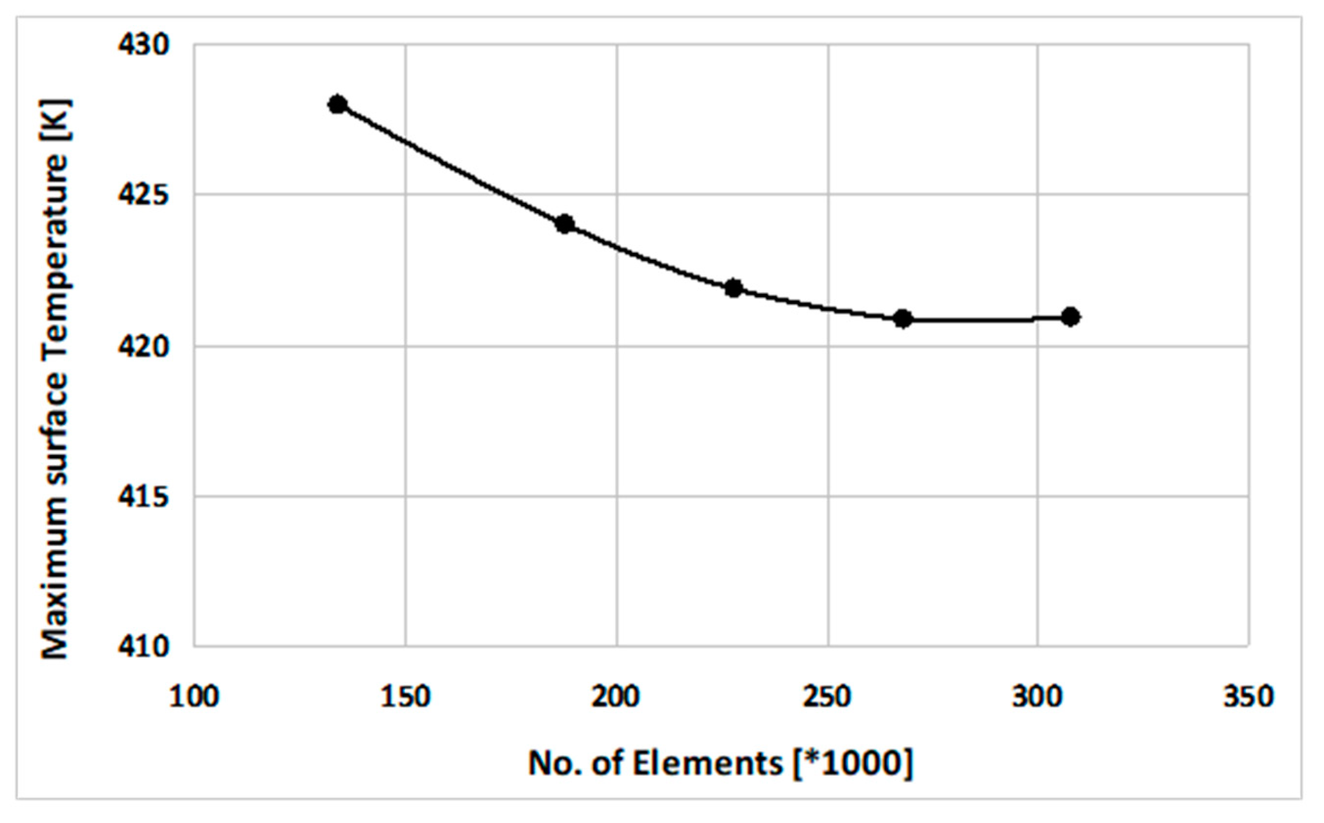
In order to find the optimal mesh of the friction clutch system, it was achieved the mesh independence test, as shown in
Figure 4, where the selected finite element model of the clutch system has 268,675 elements (1,164,367 nodes).
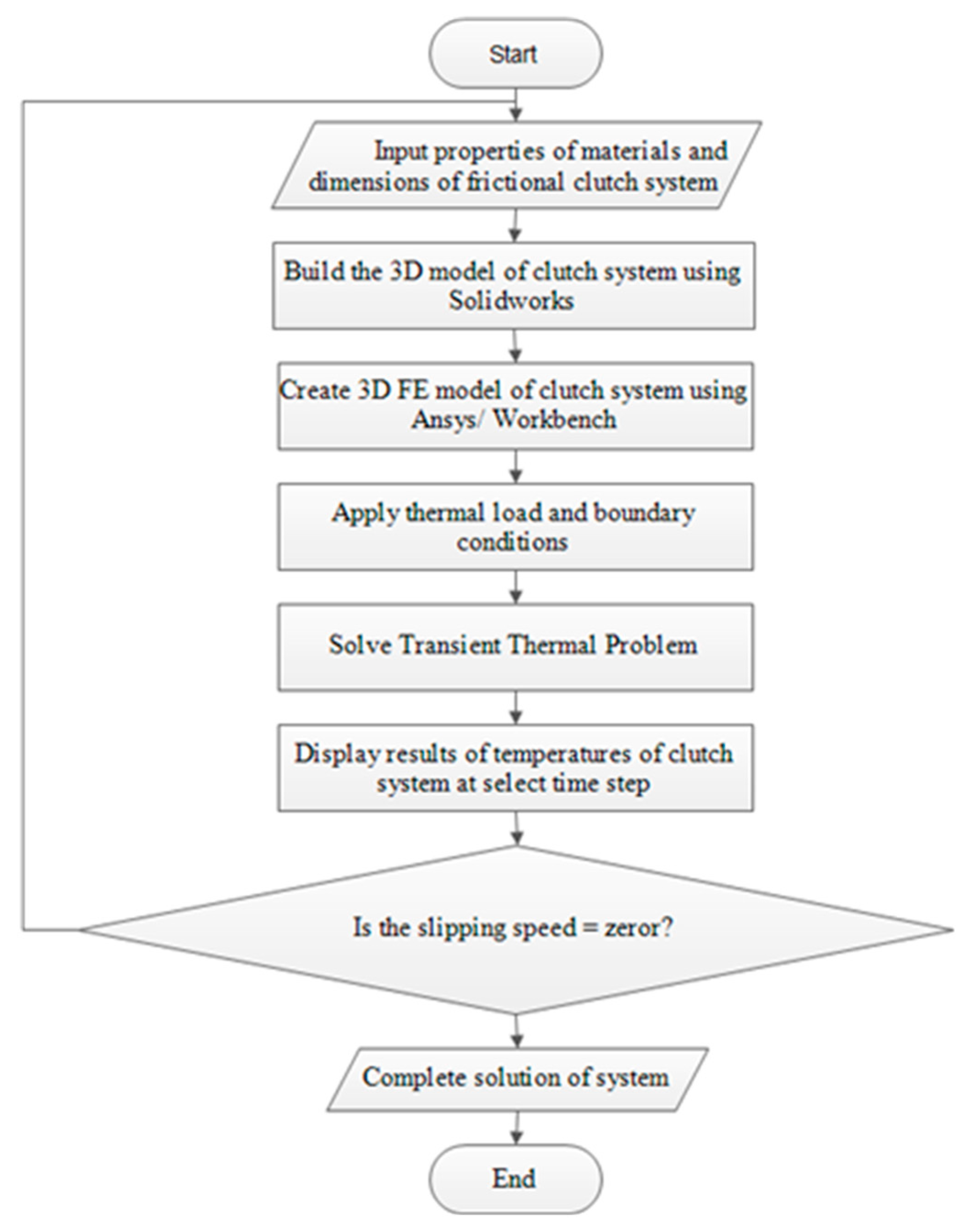
Figure 5 shows the Flowchart of the developed numerical approach (FE) to find the solution of transient thermal problem. A 3D Finite Element model (
Figure 6a) of a complete frictional clutch system was built as the first step, where it could be used to study unsymmetric load, wear and hotspot. In this analysis, the objective is to validate the results of the new numerical model with analytical solutions to be reliable for any future investigations. According to the uniform wear assumption, the frictional thermal load is uniform over the contacting area. Owing to this assumption, a part/sector of the complete FE model (1/8 of complete model) will be sufficient to simulate the thermal problem in the dry friction clutch (
Figure 6b). The selected thermal element is SOLID90 with twenty nodes and the DOF is the temperature. The reason to select this kind of element is the complex geometry of the clutch system that has many boundaries with curves.
The main development in this analysis is to extend the numerical solution from 2D axisymmetric problem [
1,
11,
20,
27,
28] to 3D solution that included all the complexities of the friction clutch system. The new solution can be applied for more complex problems that occur in the clutch system such as hotspot, wear, flash temperature, the effect of roughness, etc.
4. Analytical Model
The thermal analysis conduction by means of the finite element method was compared with results that were obtained from the one-dimensional analytical model. In order to apply this model, the following assumptions were introduced:
1. The frictional heat is totally absorbed in the normal direction to the contact surface by the friction pair elements and they are only significantly heated in the near distance from the friction zone.
2. Wear and convective heat exchange on the lateral surfaces of the clutch elements are negligible.
3. Thermal sensitivity of friction materials and the instability of friction coefficient under temperature variations are negligible due to relatively low maximum temperature level.
4. The frictional heat is uniformly distributed over the friction surface area.
5. The perfect thermal contact conditions were adopted on the contact surfaces.
These assumptions are reasonable only for the short-duration, heavy-loaded friction processes [
12,
13,
14,
15,
16]. Owing to the symmetry of the problem, it was assumed that the friction processes on the flywheel–clutch disc and clutch disc–pressure plate contact surfaces are the same. Based on the above assumptions, the one-dimensional, boundary–value problem of heat conduction formulated for a semispace–semispace tribosystem can be written as follows [
13,
14]:
All values referring to the clutch disc and flywheel (or pressure plate) will, respectively, have subscripts
c and
f. Taking into account the Equations (1)–(3). The specific friction power
, that presented in the boundary condition Equation (21), has the following form:
where
—the specific friction power (nominal value),
—inner radius of the friction surface, and the rest parameters are included in the
Table 1. The above problem of heat conduction can be written in the dimensionless form:
where,
—effective depth of heat penetration in the flywheel (or pressure plate). Based on Duhamel’s theorem, the exact solution to the initial boundary problem of heat conduction Equations (26)–(32) can be found from the following relation:
where
is the known formula obtained from solution to the problem Equations (26)–(32) for constant friction power
,
:
where
is Gauss error function and
is already defined in Equation (4). Substituting the derivative of the solution Equation (24) and the specific friction power Equation (25) into the Equation (33), it will achieve,
On the friction surface for
the Equation (36) takes the form:
After integration of Equation (37), it was achieved the solution to the initial boundary problem Equations (26)–(32), in the following form:
which is convergent to the results achieved by other researchers [
12,
13,
14].
5. Results and Discussions
This research paper consists of two parts, in the first part, a new 3D FE model of the dry friction clutch was built from scratch in order to enhance the numerical solution of the thermal problem during the slipping period. Meanwhile, in the second part, a new analytical solution was obtained based on the methodical model that was derived from scratch to obtain the variation of temperature and used it to validate the new numerical model.
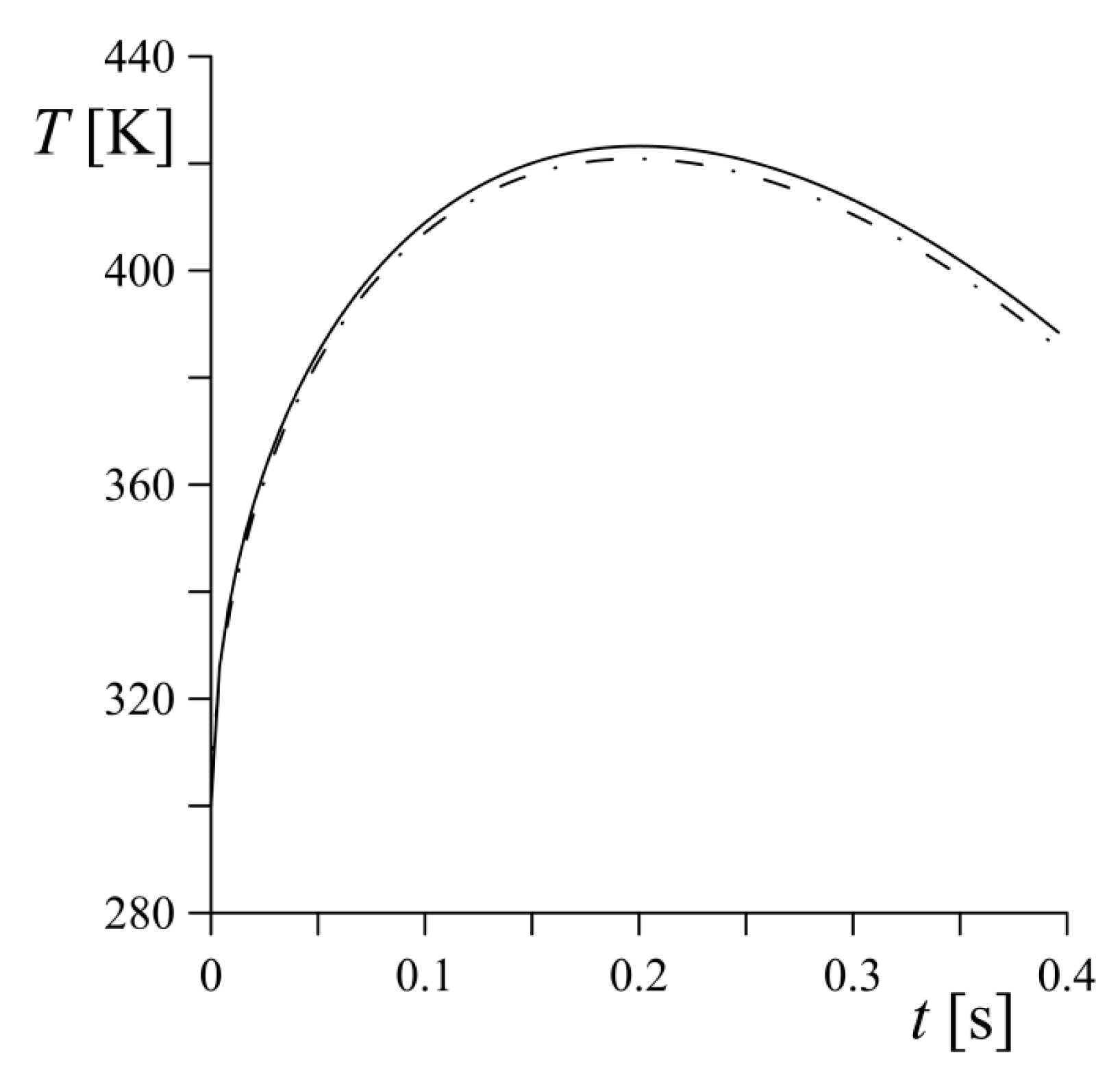
The numerical and analytical results of variations for maximum temperature that occurred in the contacting surfaces during the complete slipping period are illustrated in
Figure 7. Generally, it can be seen that the numerical results are very accurate and the maximum difference with analytical results is not exceeded 1%. According to the obtained results, it can be seen three important points in the curve that represents the thermal behaviour of the clutch system. Firstly, the initial point (
Ti = 300 K) that occurred at
ts = 0; secondly the peak point where the maximum temperature occurred (
Tmax = 443 K at
ts = 0.2 s). While, the last point is the end point that represents the end of the slipping period (
Tf = 384 K at
ts = 0.4 s). It can be observed that the peak point occurred at approximately the middle of the slipping period. Where, the maximum increasing in the temperature that occurred during the slipping period was 120.8 K. The temperatures that were generated during the sliding period were a function of many parameters, such as torque variation during the engagement period, surface roughness, level of cooling, thermal properties of the contacting materials, friction characteristics, sliding speed, etc.
Figure 8 shows the distribution of temperatures of the main elements of the clutch system (friction clutch disc, flywheel and pressure plate) at different times of the slipping period. It is observable that the distribution of surface temperature was approximately uniform, that corresponding to the applied frictional thermal load (uniform distribution). The results presented the thermal behaviour of the used frictional clutch disc, where the uniform wear rate on the contact surfaces was assumed. Based on this theory, the frictional heat generation is applied uniformly on the sliding surfaces. Additionally, the thermal behaviour of the new clutch system is essential, while the pressure will be uniform over the contacting area. This will lead to focusing the highest fractional generated at the zone of the outer disc of the clutch. This important point will be investigated deeply in the subsequent investigation.
6. Conclusions and Remarks
This research is an essential achievement in the direction of obtaining the optimal numerical and analytical simulations of the frictional clutch system. A new three-dimensional FE model was built using a developed numerical approach after verifying the reliability of the temperature results of the clutch system during start-up based on the comparison made with new enhanced analytical solutions. The main goal was to reach the highest accuracy of the numerical results, so this presented approach is the basis for designing the friction clutches.
The most important point that has been proven is the reliability of the developed numerical model after the obtained results were compared with the analytical solution of temperatures during the entire slip period. Extreme temperatures are the most important results that must be focused on, as the level of this temperature must be within the permissible temperature of the selected materials. Whereas the maximum surface temperatures occurred approximately at the mid-slide time for all cases. In addition, when assuming that the rate of wear is uniform over the clutch surfaces, the temperature distribution is uniform over the surfaces of the clutch elements, as explained in the results. The amounts of frictional heat that entered to the steel elements (flywheel and pressure plate, 92.93% of total amount of heat) were much greater than the frictional heat that entered to the friction disc (only 7.07% of the total amount of heat) due to the poor thermal properties of the friction materials. Furthermore, it was found that the highest temperatures appeared on the contact surfaces, while if it moved towards the thickness, it was found that the effect of heat generated approached zero near the middle of the thickness of the frictional material.
There are some researchers that developed finite element models of a clutch disc to study the thermal buckling, in order to find the critical value of the buckling temperature [
29]. On the other hand, some research papers focused on the mathematical modelling in order to determine the behaviour of the automotive brakes and clutches during the thermal processes, taking into consideration the unequal distribution of the heat flux and thermal conductivity. They also compared the results with experimental work in order to verify the developed mathematical models [
30,
31].
A future stage in this research project is to find the numerical solutions to more complex problems of the friction clutch system such as the effects of surface roughness, thermal stresses, unsymmetric thermal load, hotspots, etc.


 ,
, 


