Article

The INUS Platform: A Modular Solution for Object Detection and Tracking from UAVs and Terrestrial Surveillance Assets

by
Evangelos Maltezos
*,
Athanasios Douklias
,
Aris Dadoukis
,
Fay Misichroni
,
Lazaros Karagiannidis
,
Markos Antonopoulos
,
Katerina Voulgary
,
Eleftherios Ouzounoglou
and
Angelos Amditis
Institute of Communication and Computer Systems (ICCS), 15773 Zografou, Greece
*
Author to whom correspondence should be addressed.
Submission received: 24 December 2020 / Revised: 22 January 2021 / Accepted: 25 January 2021 / Published: 29 January 2021
(This article belongs to the Special Issue Recent Advances in Computation Engineering)

Abstract

:
Situational awareness is a critical aspect of the decision-making process in emergency response and civil protection and requires the availability of up-to-date information on the current situation. In this context, the related research should not only encompass developing innovative single solutions for (real-time) data collection, but also on the aspect of transforming data into information so that the latter can be considered as a basis for action and decision making. Unmanned systems (UxV) as data acquisition platforms and autonomous or semi-autonomous measurement instruments have become attractive for many applications in emergency operations. This paper proposes a multipurpose situational awareness platform by exploiting advanced on-board processing capabilities and efficient computer vision, image processing, and machine learning techniques. The main pillars of the proposed platform are: (1) a modular architecture that exploits unmanned aerial vehicle (UAV) and terrestrial assets; (2) deployment of on-board data capturing and processing; (3) provision of geolocalized object detection and tracking events; and (4) a user-friendly operational interface for standalone deployment and seamless integration with external systems. Experimental results are provided using RGB and thermal video datasets and applying novel object detection and tracking algorithms. The results show the utility and the potential of the proposed platform, and future directions for extension and optimization are presented.

1. Introduction

Situational awareness is a critical aspect of the decision-making process in emergency response and civil protection, and requires the availability of up-to-date information on the current situation, e.g., on traffic infrastructure or on current location and availability of security and medical staff [1]. In this context, the related research should not only encompass developing innovative single solutions for (real-time) data collection, but also on the aspect of transforming data into information so that the latter can be considered as a basis for action and decision making. This aim also covers issues of visualization and dissemination of information acquired from different sources, taking the specific technological, organizational, and environmental settings of an end-user into account. According to [2,3], the definition of situation awareness is: “Situation awareness is the perception of the elements in the environment within a volume of time and space, the comprehension of their meaning, and the projection of their status in the near future”. In this context, situation awareness underscores situation assessment in order to make accurate forecast in dynamic and complex environments. The authors in [4] decomposed a relevant meaning of situation awareness to the following three elements: (i) perception of the current situation, (ii) comprehension of said situation, and (iii) projection of the future condition. In our work, we focus on the first element, automated perception of the current situation. The perception of the current situation refers to the perception of information elements in the environment by the operator [5]. For instance, for a navigator, the information elements such as GNSS position, speed, course heading, etc., are required to be perceived first in order to be aware of the external state environment. The comprehension of the situation refers to the comprehension of the situation by the operator by deriving meaning from the perceived information elements. This level of awareness provides a meaning of the existing state and helps the operator to determine a course of action (if any) which will be required. The projection of the future condition refers to the ability of operator to make projections about the future state of the system basis on the derived comprehension of situation. For instance, for a navigator, parameters such as the vector extension of the target’s radar simulation provides a projected view of the basis on which it may be possible to predict a future outcome of the system state.
In search and rescue applications, investigation, containment, and search are required to be done as quickly as possible to prevent the increase in risk for the safety of a missing person [4]. The investigation task is used to collect crucial information about the subject including their plans of activity before they got lost. In this way, the investigators are able to understand what area has the highest probability of the person’s whereabouts. On the other hand, the containment plan aims to prevent the search area from expanding. Thus, the more time has passed before the missing person is found, the bigger the search area becomes. An unmanned aerial vehicle (UAV) situational awareness can significantly contribute to scanning the search area quicker and possibly finding the missing person sooner, in addition to reducing the risk to the search team’s safety.
In disaster response applications, in the aftermath of a disaster, there is an immediate need for emergency services. For cases where it is not possible to find people in need of assistance, a search is required to find these missing people. In this context, UAVs can be deployed to scan the affected area for potential unknown victims and obtain video feeds. Most of these systems mainly depend on human–agent collectives or crowdsourcing to understand where potential victims or structure damage occurred. For such situations, automatic detection is preferable, even if some human monitoring is kept for redundancy. Alternatively, many surveillance systems already operate autonomously or semi-autonomously. However, some of these provide only UAV or only terrestrial assets. Thus, integrated situational awareness systems that include both UAV and terrestrial assets with multipurpose capabilities can further contribute to the related research and cover the end-user needs. In the applications associated with emergency situations, the detection and tracking of several objects of interest, such as vehicles and persons, and recognizing their actions in real-time or near real-time can play a crucial role for preparing an effective response [4]. Human resource in situational awareness is a key concern because human performance is limited by fatigue and waning concentration when continuously watching a video feed.
In [6], some situational awareness requirements in autonomous ships are provided from three main different viewpoints, namely: (i) requirements for vessels, (ii) requirements for sensing, and (iii) requirements for software. A relevant study to define a goal-directed task analysis for situation awareness information requirements for maritime navigation is provided in [5]. Through their analysis one major goal among others was recognized as “Navigate the vessel safely from pilot point to berth or vice versa”. This major goal was further decomposed into four goals, namely: (i) ensure appropriate information exchange with pilot point; (ii) execute the passage plan safely and effectively; (iii) monitor the progress and use resources optimally; and (iv) maneuver safely either working together with the pilot point or working without the pilot point.
Extended information for situation awareness requirements for a critical infrastructure monitoring operator was also provided in [2]. The purpose of their research was to define a common requirement base that can be used when designing a critical infrastructure monitoring system or a user interface to support situation awareness. Such requirements are able to be used during system or user interface evaluation, and a guide for the aspects to emphasize when training new critical infrastructure monitoring operators. In this context, the critical infrastructure sectors are defined in three levels. The first level covers the topics of information and telecommunication, power/energy, and water. The second level covers the topics of banking finance, transportation, and chemical industries. The third level covers the topics of the defense industry, postal shipping, agriculture/food, public health, and emergency services. Furthermore, the study highlighted the situation awareness requirements of a critical infrastructure monitoring operator in the following goals: (i) identify incidents (ongoing incidents, affected services and systems, priority order incidents, etc.); (ii) monitor resource management (ongoing incidents, current services and systems, validity of incidents, etc.); (iii) analyze and communicate internally (ongoing incidents, possible future incidents, etc.); (iv) determine to whom the information should be communicated; and (v) determine incidents worth mentioning. By comparison, in [7] the authors highlighted the usefulness of the design of information systems and network components for situational awareness to ensure that systems and networks are secure, reliable, and operational. This includes actions taken via computer networks to protect, monitor, analyze, detect, and respond to cyber-attacks, intrusions, disruptions, or other perceived unauthorized actions that could compromise or impact defense information systems and networks. A review of situation awareness assessment approaches in aviation environments is provided in [8]. In their study, many aspects of situation awareness were examined, including the classification of situation awareness techniques into six categories (freeze-probe techniques, real-time probe techniques, post-trial self-rating techniques, observer-rating techniques, performance measures, and process indices), and different theoretical situation awareness models from individual, to shared or team, and to distributed or system levels. Quantitative and qualitative perspectives pertaining to situation awareness methods and issues of situation awareness for unmanned vehicles were also addressed.
UAVs as data acquisition platforms and autonomous or semi-autonomous measurement instruments have become attractive for many applications in emergency operations. The possibility of high-risk flights, cost-effectiveness, high accuracy navigation, high image overlaps, and large-scale images and videos from several type of sensors (multispectral, hyperspectral, thermal, LIDAR, SAR, gas or radioactivity sensors, etc.) are the main advantages of UAVs. Their mobility and flexible deployment, ability to provide real-time data, and recent developments in powerful on-board embedded processing hardware make UAVs ideal candidates for sensing and monitoring applications. There are several challenges in geomatics that are still to be overcome with novel developments [9,10,11] in order to provide accuracy, economy, rapidity, and automation. These geomatics fields are: (i) the on-board and real time data analysis and processing, and power efficiency; (ii) navigation and position/orientation determination; (iii) data fusion; (iv) on-board data storage and transmission; (v) UAV control, obstacle sense, and avoidance; (vi) autonomous flight and exploration; (vii) control and automation of on-board components; and (viii) object positioning and orientation.
Finally, computer vision, image processing, and machine learning have been attracting increasing amounts of attention in recent years due to their wide range of applications and recent breakthroughs in many important problems. In this context two core problems, object tracking [12,13,14,15,16] and object detection [17,18,19,20,21], are under extensive investigation in both academia and real-world applications. With the rapid development in deep machine learning, more powerful tools, which are able to learn semantic, high-level, deeper features, have been introduced to address the problems existing in traditional architectures [22,23]. In general, the object detection methods can be categorized: (i) to those that employ hierarchical, rule-based techniques such objected-based image analysis (OBIA) [24], and (ii) to those that employ machine learning techniques, such as deep learning, through convolutional neural networks (CNNs). Although OBIA methods extract satisfactory results, they are tailored for a particular scene layout and task. Thus, OBIA methods are affected by the used parameters and the adopted features, which are usually application dependent. Therefore, they present low generalization capabilities because the tuned parameters of one study area cannot be directly applied to another region. Machine learning techniques are flexible and data driven methods, requiring only training samples to well generalize the properties of each available class. Thus, they provide high generalization capabilities, that is, robustness against data being outside the training set.

2. Approach

In the literature there are several studies that have design efficient schemes to enhance situational awareness [4,25,26,27,28]. However, their limitations are that they: (i) implement only object detection or only object tracking processes, (ii) consider only UAV or only terrestrial assets, and (iii) employ only RGB or only thermal cameras. Our contribution is the design of an efficient, integrated, and modular UAV and terrestrial based situational awareness system that can support humans in analyzing the video feed and provide crucial information of detected objects in an area of interest. The proposed multipurpose based situational awareness system, namely the INtelligentUxV Surveillance—INUS platform, is aimed to be used for several applications and consists of the following main core entities: (i) an aerial unmanned platform (UAV), (ii) a terrestrial system, (iii) the UAV pilot’s workstation, and (iv) the intelligence officer’s workstation. The system exploits novel UAV and terrestrial feature technologies such as on-board processing, supports the integration of optical and thermal sensors, and applies robust and effective computer vision, image processing, and machine learning techniques. The INUS platform is focused on the first element of the situation awareness component, i.e., the “perception of the current situation”. Our approach is based on the following main pillars:
(i)
Modular architecture that facilitates the design of a multipurpose situational awareness system that exploits aerial assets from UAVs and terrestrial assets from fixed positions.
(ii)
Provision of localized object detection and tracking events exploiting novel computer vision, image processing, and machine learning techniques that can be efficiently performed in complex scenes. Object detection and tracking from RGB and thermal videos is a demanding task due to radiometric distortions (e.g., shadows, reflections, etc.), occlusions, repetitive object patterns, multiple moving targets, simultaneous existence of several types of objects in the scene, etc.
(iii)
User friendly operational interface for standalone deployment and for seamless integration with external systems such as surveillance systems, decision support systems, and command and control systems (C2s).
The human operator that controls the intelligence officer’s workstation can be assumed as the human-in-the-loop with expertise in the domain of the application and the use case. The INUS platform supports several functionalities that the operator can manage in real time as the on-board process is running, such as: (i) switch to UAV or terrestrial asset; (ii) select zoom level of a camera; (iii) control the camera of the UAV; (iv) switch between RGB or thermal camera; and (v) choose an event and focus it on a map component. Such functionalities that run continuously can significantly assist and support the operator in order to perceive, assess, and supervise the current situation, and thus to plan and/or design relevant actions, interventions, or confirmations.
It should be noted that operators of INUS who register and/or process the images, videos, geolocation, object detection and tracking, and any other data related to an identified or identifiable person are subject to General Data Protection Regulation (GDPR), EU Data Protection Directive 95/46/EC.

3. INUS Platform

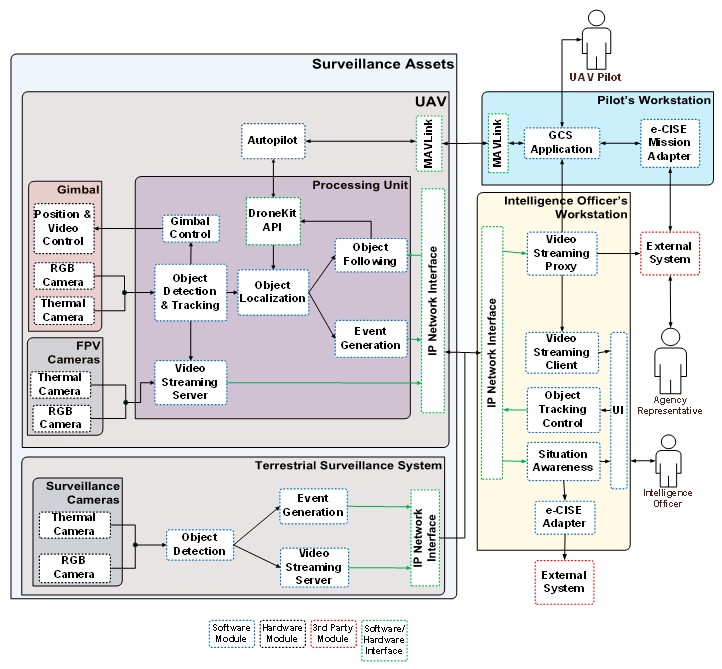
3.1. Proposed System

The components of the INUS platform Hardware-HW and Software (SW), their functions, data flows, and interfaces are depicted in the functional architecture in Figure 1. From an operational point of view the INUS platform is operated by a certified UAV pilot and the intelligence officer. The UAV pilot is tasked with the remote control of the UAV and mission planning through a dedicated workstation which provides a head-up display (HUD) that combines first-person view video from cameras on board the UAV with navigation and status information. This setup enables beyond line-of-sight operation of the UAV, during day and night. In the current design an extended Common Information Sharing Environment (e-CISE) compatible mission adapter is implemented with the purpose of accepting UAV flight missions from third party components such as Command and Control Systems (C2s) and presenting them to the pilot for flight plan extraction. The mission adapter and the interface to any external systems is configurable according to the needs of the systems to be integrated.
The payload of the UAV is comprised of an electro-optical sensor and a processing unit capable of executing computer vision algorithms and image processing in real time under power consumption constraints (e.g., 15 or 30 W power profiles), a valuable feature that leads to reduced payload weight due to the reduction in the required battery capacity and thermal solution weight. It should be noted that in addition to a serial connection link with the autopilot hardware module, for the purpose of retrieving localization information, the payload functions independently, even having its own power supply and wireless communication link, and can thus be readily deployed on board other flying platforms.
The terrestrial system complements the focused surveillance capability of the UAV by providing a set of fixed surveillance assets, consisting of a camera set of sensors (RGB camera, thermal, and/or similar) and a processing unit performing an object detection process, with the aim of early detection. The terrestrial asset may be deployed at fixed known locations, deployed on demand at temporary locations, or deployed on manned or unmanned vehicles/robotic systems. The deployment decision is based on the actual use case, the operational requirements, and the surveillance mission and target. An example of fixed installation is at the perimeter of critical infrastructure for the detection of illicit activities of critical areas.
The primary output of both the UAV and the terrestrial system is video streams annotated with bounding boxes indicating the detected objects with messages containing information about the location and type of those objects. These are gathered at the intelligence officer’s workstation and presented on a map to provide situation awareness. In addition, the system is able to forward localized information to C2s or other interested parties through its e-CISE adapter. Because the system is able to both forward information and receive UAV missions through its e-CISE compliant adapters, in addition to being able to function in a standalone fashion, it can be integrated in other e-CISE aware surveillance or C2 systems.
Regarding the UAV, the intelligence officer can invoke tracking functionality to have the electro-optical sensor of the UAV continuously track an object or instruct the UAV to follow it. The INUS platform was built with low cost and versatility in mind. To this end we attempted to use as many commercial off-the-shelf modules as possible to keep the cost of the hardware low, and exclusively open-source software modules to enable customization and development of new features. Although the system is aimed at a specific application, many of the components used, such as the UAV or the fixed terrestrial assets, can be utilized in a variety of different applications, such as vehicle traffic counting and aerial mapping, contributing to the reusability of the platform.

3.2. Features and Hardware

One of the core modules of the INUS platform is the UAV, delivering most of the platform’s capabilities and constituting the single most expensive module. As depicted in Figure 2, it is built upon the octocopter DJI S1000 airframe, which is rated for a takeoff weight of up to 11 Kg and can tolerate the loss of one off its rotors. For the control and stabilization of the UAV the open autopilot hardware pixhawk 2.1 is utilized, which is connected to a long-range radio module with antenna diversity, data encryption, and Frequency-Hopping Spread Spectrum (FHSS) for the purpose of transferring the telemetry from and to the ground control station. A real-time kinematic (RTK) base station is also included in the system, with Radio Technical Commission for Maritime Services (RTCM) messages injected into the telemetry stream, transmitted to the autopilot module, and routed to the RTK rover module on board the UAV to enable its DGNSS capability.
Because it can remain stationary, the RTK base station can achieve enhanced absolute position accuracy, which is transferred to the UAV to be utilized for localization and position aware applications. The main purpose of the UAV is to provide video streams and perform object detection and tracking processes. Raw video requires a bandwidth in the order of magnitude of Gbps which is impractical for wireless transmission, and therefore video compression has to be applied in order to reduce the required bandwidth.
Object detection is realized through deep convolutional neural networks (CNNs) (see Section 6) which have high requirements for processing power and benefit in particular from architectures utilizing mass parallelism such as GPUs. To meet these needs the Jetson AGX Xavier is installed on board the UAV, and is assumed to be a powerful unit achieving better performance compared to other units [29,30]. It is an embedded processing system capable of performing video compression and CNN inference though its dedicated hardware, while having low weight and high energy efficiency. In addition to its specialized hardware, it features multiple CPU cores and a GPU which make it a powerful general-purpose processing unit adding greatly to the flexibility of the platform. The utilization of the aforementioned component not only provides for the on-board processing capability of the UAV, but is in line with the general trend for edge processing to reduce required bandwidth and improve response time. In particular, by performing the detection and tracking on board the UAV, we are able to remove the encoding/decoding and communication latency from the control loops responsible for object tracking and following in conjunction with greatly easing the computational burden for the intelligence officer’s workstation, thus delivering a more scalable system.
Two sets of cameras are installed on board the UAV. The first set is tasked with providing first person view (FPV) video to the UAV’s pilot as a visual aid to flying and includes one RGB camera for day and a thermal camera for night. The second set of cameras and the gimbal make up the electro-optical sensor. The gimbal is necessary for the stabilization of the cameras due to the vibrations caused by the UAV’s motors and the changes in orientation caused by the UAV’s movement. Furthermore, it provides the capability to point the cameras in an arbitrary direction in space. Two cameras are installed on the gimbal: an RGB camera with 30× optical zoom and full HD @ 60fps video capability, and a thermal camera with resolution 640 × 512 pixels. The wireless link between the UAV’s payload and the intelligence officer’s workstation is realized through 802.11b network adapters operating in ad hoc mode.

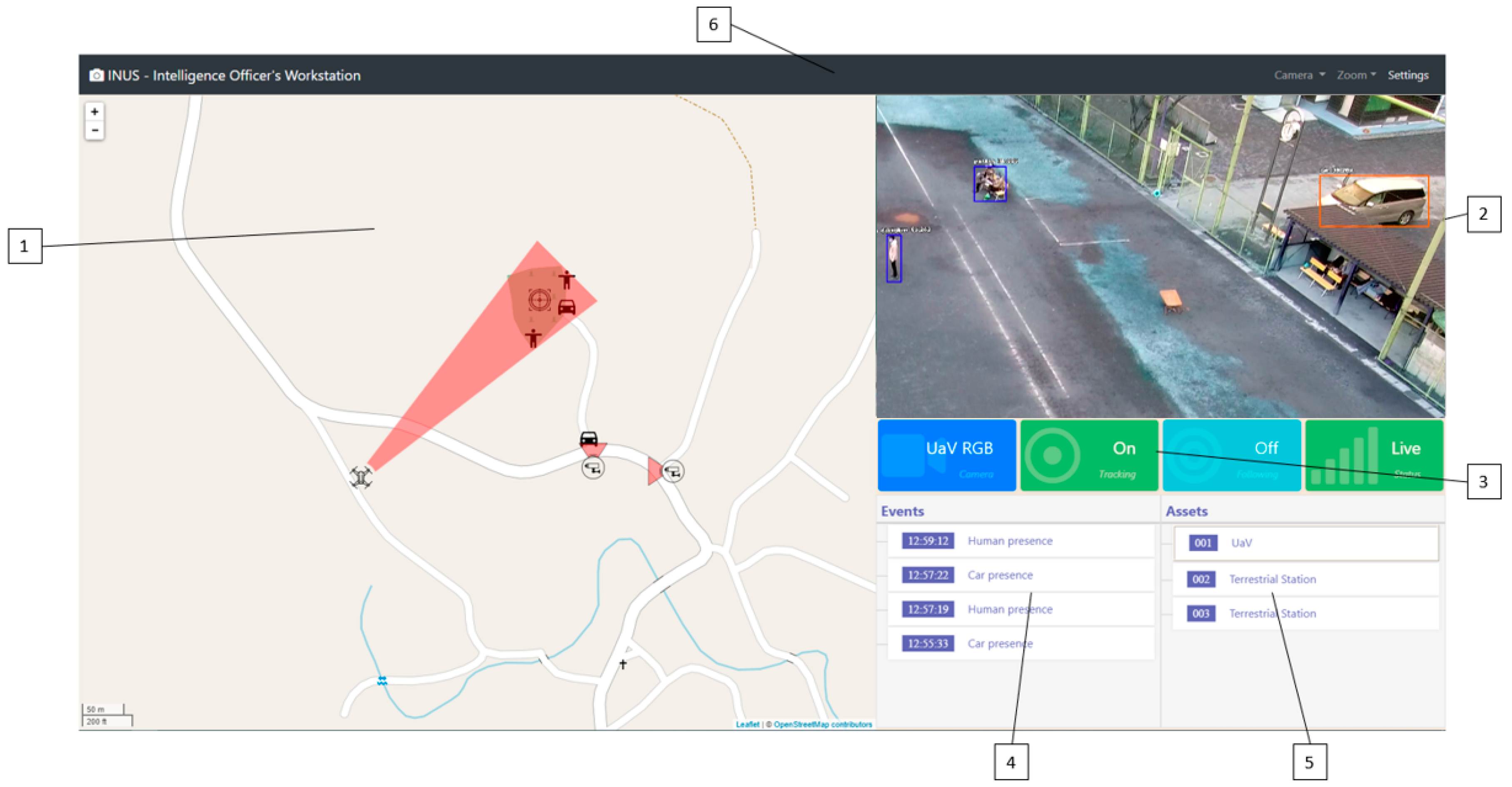
3.3. Intelligence Officer’s Workstation

The intelligence officer’s workstation is tasked with collecting and presenting all of the information generated by the intelligence assets. To achieve this, multiple components were developed and deployed in the workstation.
  • Video Streaming Proxy Server: Janus is a general purpose WebRTC Server capable of setting up a WebRTC media communication with a browser, acting as an intermediate between the UAV and terrestrial assets, that generates video streams and any component that consumes those video streams.
  • Message Broker: Eclipse Mosquitto is an open source (EPL/EDL licensed) message broker that implements the MQTT protocol. All messages from and to UAV and terrestrial assets are produced and consumed through appropriate topics on this message broker.
  • Intelligence Officer’s Workstation Back-End: A back-end service was developed that consumes data from the message broker and stores them in a database. At the same time, it exposes a REST API for communication with the front-end. It was developed using Python/Flask and MongoDB.
  • Intelligence Officer’s Workstation Front-End: A web application was developed that consumes data from the back-end and displays it to the intelligence officer. At the same time, the intelligence officer is capable of issuing several commands to the UAV and terrestrial assets. These commands are: (i) choose an event and focus it on the map; (ii) choose a UAV or terrestrial asset and focus it on the map; (iii) choose a camera on the UAV or terrestrial asset and show a video stream from that camera; (iv) change the zoom level of a camera on the UAV or terrestrial asset (only if supported); (v) control the camera of the UAV either by using the map to point to a specific location or by interacting with the video player; and (vi) draw a bounding box on the video player and start tracking the object in the bounding box.
Figure 3 provides an example snapshot of the User Interface of the intelligence officer’s workstation on the OKUTAMA dataset where:
  • Map component: Used to represent the geolocalized information of the platform (assets, events, etc.).
  • Streaming video player: Main task is to show the selected video stream, manipulate the camera, and start tracking and following of an object.
  • Status bar: Used to display critical information in the form of colored boxes. This interactive display method is used to emphasize certain status information (e.g., the connection with the UAV or terrestrial asset, status of tracking objects) with the use of color (green indicates normal status, red indicates alert status, blue indicates general information) and the use of animations (a pulsing animation is triggered on alert status).
  • Event list: A list of the events that has been detected by the platform.
  • Asset list: A list of the UAVs or terrestrial assets that are being handled by the platform.
  • Top menu: Supplies access to specific functions, such as camera drop down menu, zoom drop down menu, and settings menu.

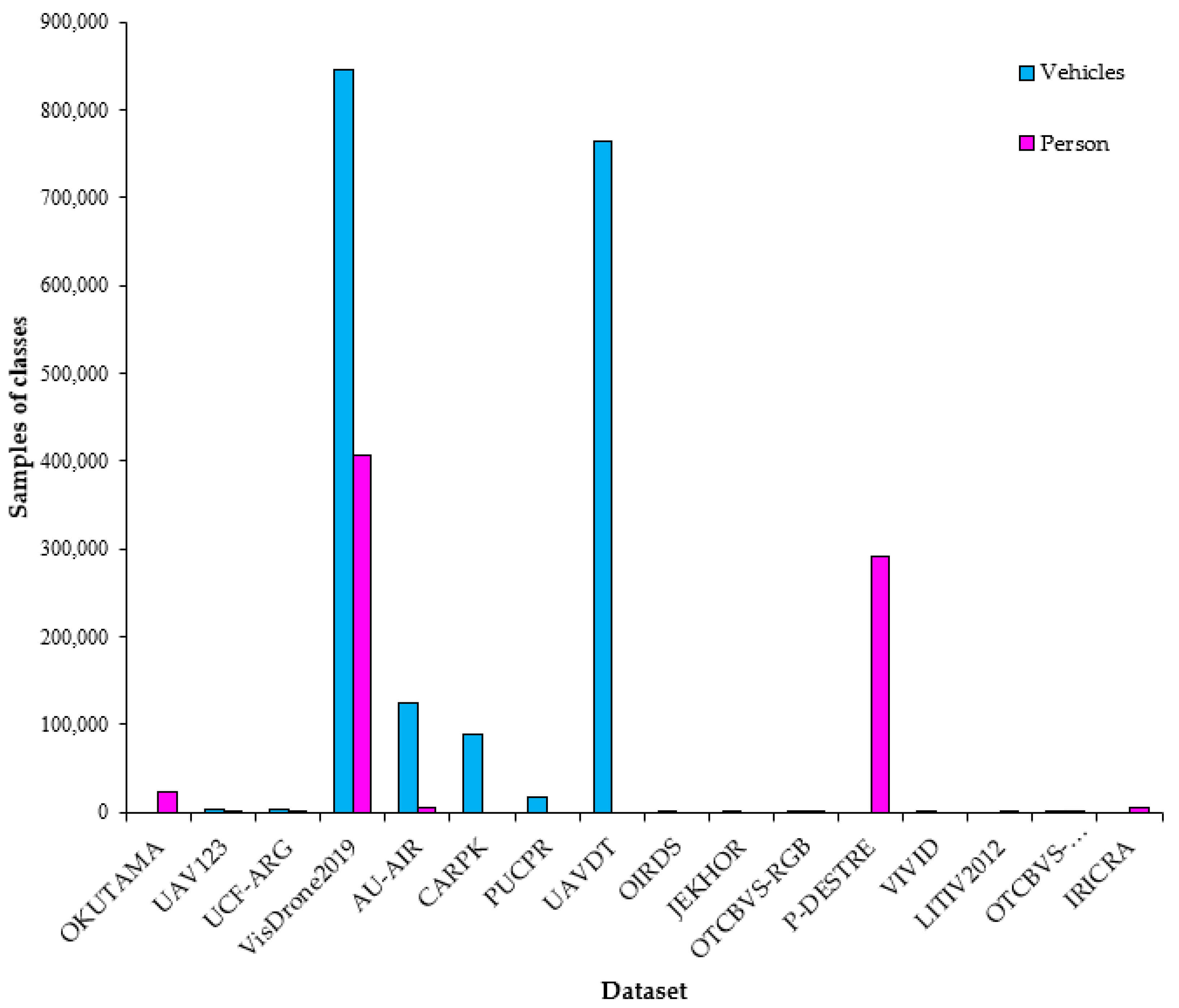
4. Datasets for Experiments and Training

The INUS platform incorporates a variety of well-known and novel computer vision and image processing algorithms for the object tracking and detection tasks. To verify the utility and functionality of the employed algorithms, several experiments were performed by using selected free available video datasets associated with aerial views from RGB sensors: (i) OKUTAMA [31], (ii) UAV123 [32], (iii) UCF-ARG [33], (iv) VisDrone2019 [21], (v) AU-AIR [34], (vi) CARPK [35], (vii) PUCPR [35], (viii) UAVDT [36], (ix) OIRDS [37], (x) JEKHOR [38], (xi) OTCBVS-RGB [39], (xii) P-DESTRE [40], and from thermal sensors: (i) VIVID [41], (ii) LITIV2012 [42], (iii) OTCBVS-THERMAL [39], (iv) IRICRA [43]. Table 1 depicts sample views from each dataset. In addition, real time thermal and RGB videos were captured in real case scenarios. Such datasets depict several scenes captured from several spectral sensors and with variable pixel resolution.

5. Object Tracking

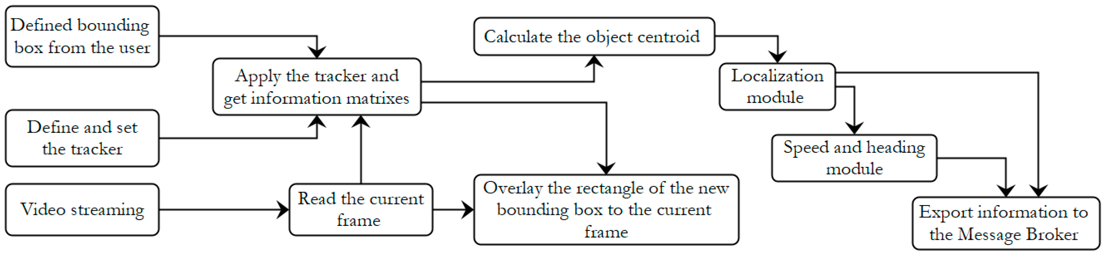
5.1. Object Tracking Module

The object tracking module is responsible for tracking persons or vehicles as the camera streaming is running. The following object tracking algorithms are employed: (i) MedianFlow [44], (ii) Boosting [45], (iii) GoTURN [46], (iv) Mosse [47], (v) Channel and Spatial Reliability Tracking-CSRT [48], (vi) Tracking–Learning–Detection-TLD [49], (vii) Kernelized Correlation Filter-KCF [50], and (viii) Multiple instance learning-MIL [51]. The initialization of the trackers is started by the user by defining a bounding box surrounding each object of interest from the start frame. Then, the tracking process continues automatically. It should be mentioned that more than one object can be tracked, thus, multiple object tracking can be performed maintaining the assignment of unique IDs and the indicated set of bounding boxes from the user. Event information is also extracted associated with: (i) output array that contains the position box points and the centroid box point of the tracked objects, and (ii) the corresponding datetime. The object tracking module is provided only for the UAV asset and is based on the Python programming language with the OpenCV library. In the following, the corresponding workflow of the object tracking module in each camera frame is described and depicted as workflow in Figure 4:
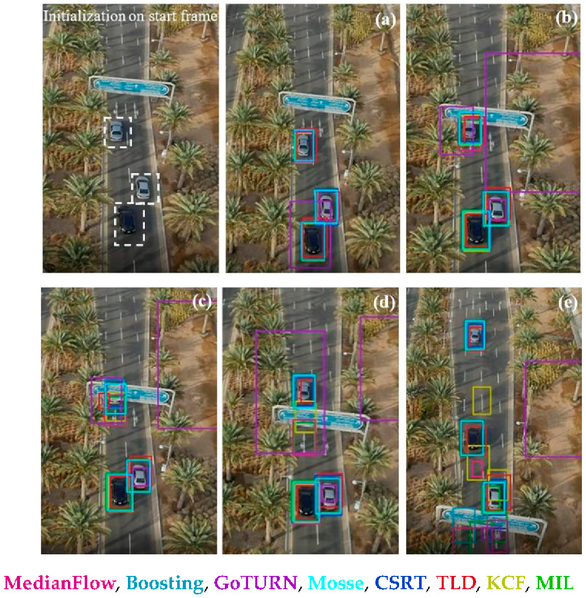
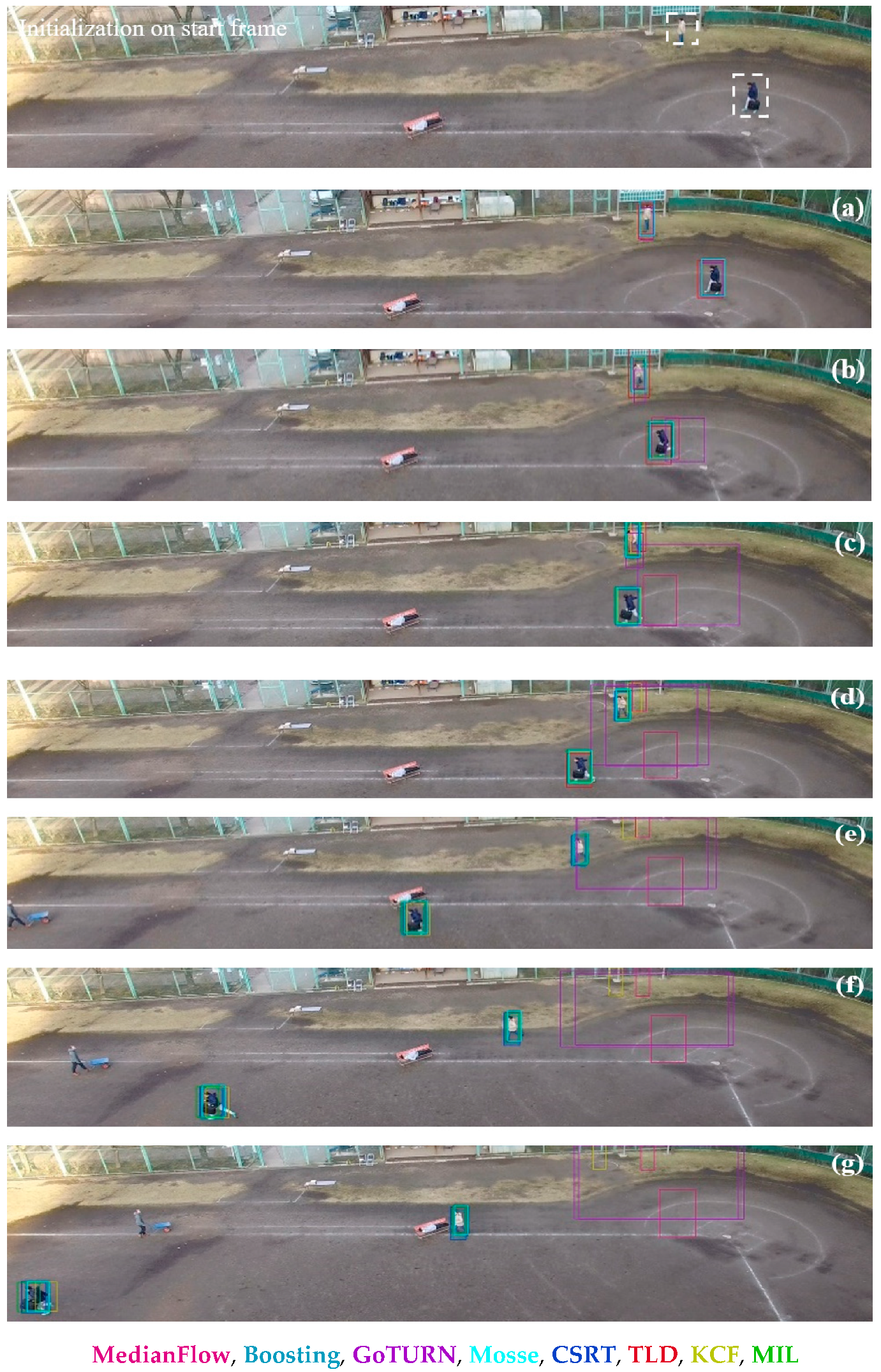
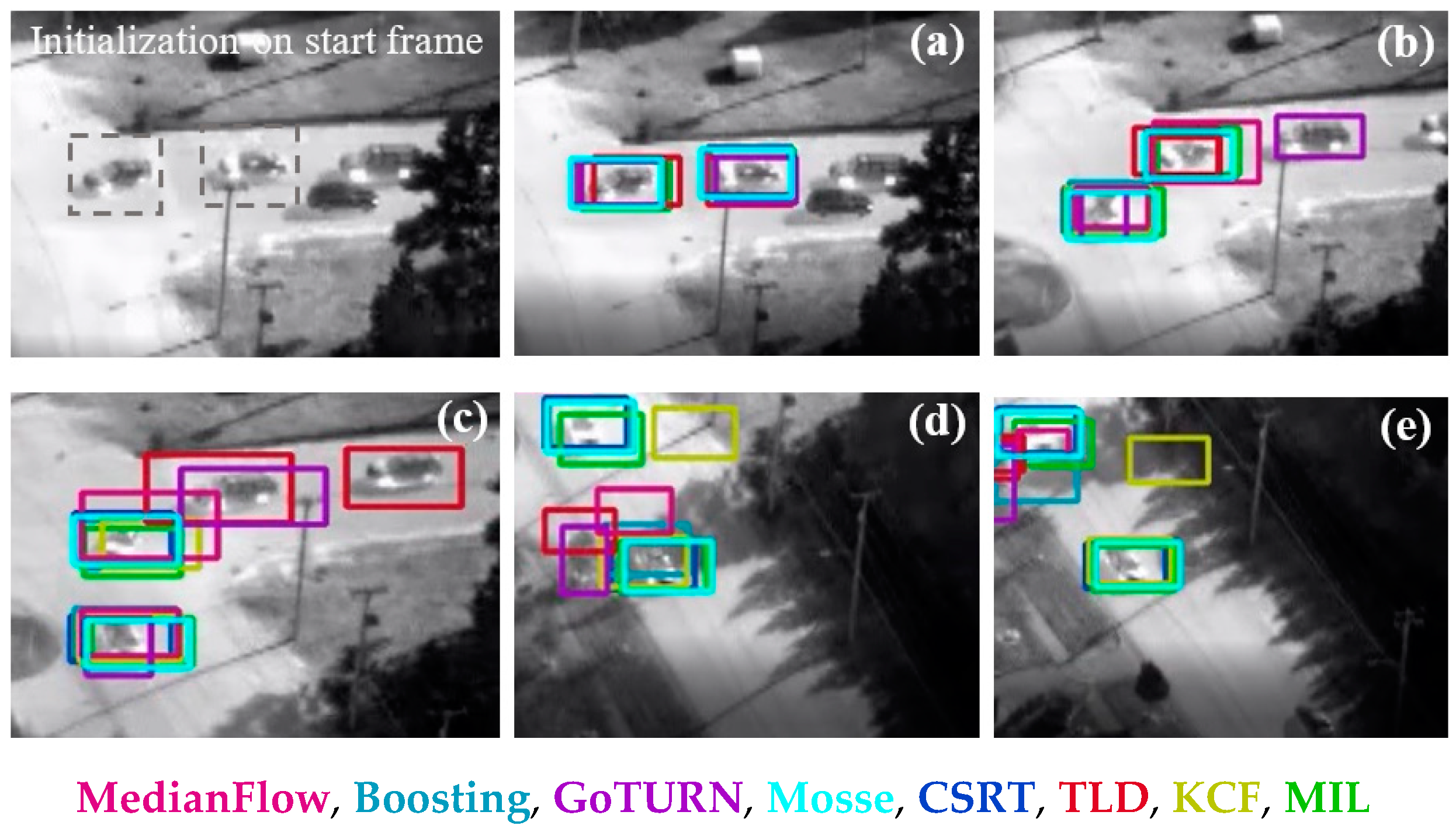
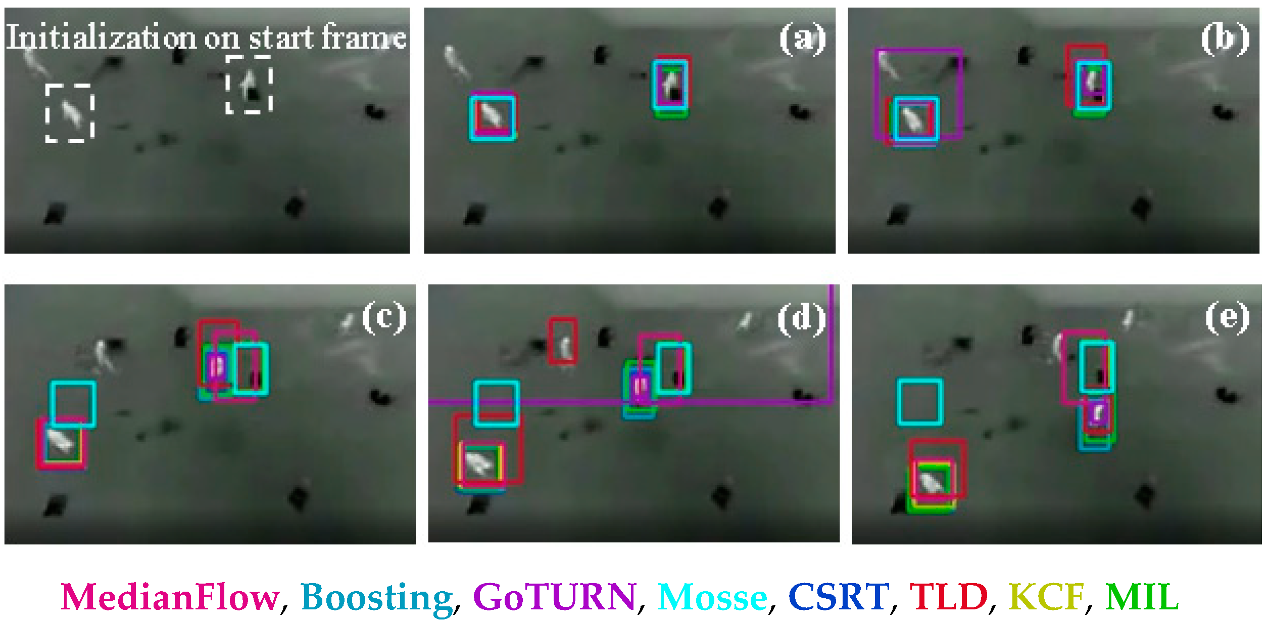
  • Define and set the tracker. The object tracker is predefined among the: (i) MedianFlow, (ii) Boosting, (iii) GoTURN, (iv) Mosse, (v) CSRT, (vi) TLD, (vii) KCF, and (viii) MIL.
  • Read the current frame of the camera streaming and the image coordinates of the defined from the user bounding box on the starting frame.
  • Apply the tracker and get the matrix object name and matrix box point. The matrix object name includes the name of the tracked object (person or vehicle). The matrix box point includes the bounding box (i.e., the top left and the bottom right image coordinates) of the tracked object.
  • Overlay the rectangle of the matrix box point to the current frame of the camera streaming.
  • Calculate the object centroid (as image coordinates) of the bounding box.
  • Import the object centroid to the localization module and calculate the corresponding WGS’84 coordinates (latitude, longitude) and UTM projection coordinates. The localization module is described in Section 7.
  • Import the Universal Transverse Mercator (UTM) projection coordinates of the tracked object to the speed and heading module. The speed and heading module is described in Section 7.2.
  • Export the matrix object name, the matrix box point, the WGS’84 coordinates (latitude, longitude), the speed and the heading to the Message Broker (see Section 3.3).

5.2. Experiments

For the MedianFlow, CSRT, KCF, and Mosse algorithms, a tracking lost object function is available to alarm the tracker for cases of lost tracked objects. The image coordinates of the centroid box point of a tracked object can be used to support the gimbal camera rotation movement.
Figure 5, Figure 6, Figure 7 and Figure 8 depict the experimental results of the multiple object-tracking process on the UAV123, OKUTAMA, VIVID, and LITIV2012 video datasets, respectively. Assessing qualitatively the experimental results on the RGB video datasets (OKUTAMA and UAV123), the Mosse tracker seems that achieves the best performance compared with the other trackers. By comparison, based on the experimental results on the thermal video datasets (VIVID and LITIV2012), the CSRT tracker achieves the best performance compared with the other trackers. However, to extract a general overview for the performance of each tracking algorithm, an extended experimental analysis is required in terms of: (i) variable initialization of the size of the bounding boxes that contain proper color values; (ii) variable sensor cameras; (iii) variable pixel resolution; (iv) computational time; (v) variable perspectives of the objects; and (vi) variable datasets of complex scenes with occlusions, shadows, repetitive patterns, etc.

6. Object Detection

6.1. Object Detection Module

The object detection module is responsible for detecting persons and vehicles as the camera streaming is running. Here, the objects of interest are cars/vehicles and persons. In this study, the following methods were adopted for the object detection task for the classes of persons and cars:
  • Three novel deep learning models that employ CNNs namely: (i) YOLOv3 [52], (ii) TinyYOLOv3 [53], and (iii) RetinaNET [54].
  • Custom deep learning YOLOv3 model.
  • An OBIA technique based on a thresholding/rule-based model that considers color values and pixel area.
The YOLOv3, TinyYOLOv3, and RetinaNET models have recently proved their robustness for a variety of applications [55,56]. To assess the performance of such models, pretrained weights were used. It should be mentioned that YOLOv3, TinyYOLOv3, and RetinaNET models have been trained mainly with terrestrial RGB imagery and not with thermal imagery [57]. Thus, to cover the object detection task using the thermal video datasets, the aforementioned OBIA rule-based technique is performed. For the deep learning models, event information is extracted associated with: (i) the class of each detected object and the corresponding datetime, (ii) output array that contains the corresponding probability percentages and position box points, and (iii) output count for unique object classes per processed frame, per second, and per minute. For the OBIA technique, event information is extracted associated with: (i) the detected objects and the corresponding datetime; (ii) output array that contains the corresponding position box points; (iii) output array that contains the used color threshold values that correspond to the detected objects; and (iv) the area of the pixel segments that correspond to the detected objects. The color and area thresholds can be tuned from the user to optimize the object detection results.
The object detection module is based on the Python programming language using the OpenCV, Tensorflow, and ImageAI libraries. In the following outline, the corresponding workflow of the object detection module in each camera frame is described:
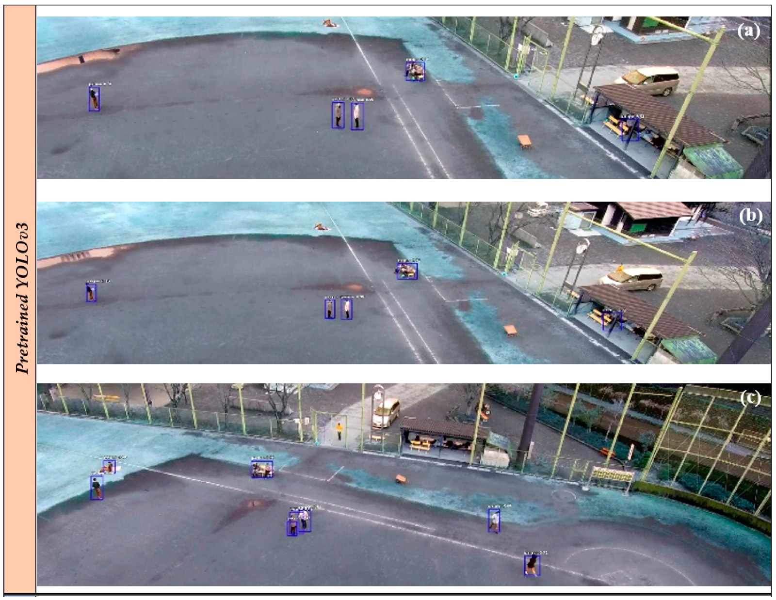
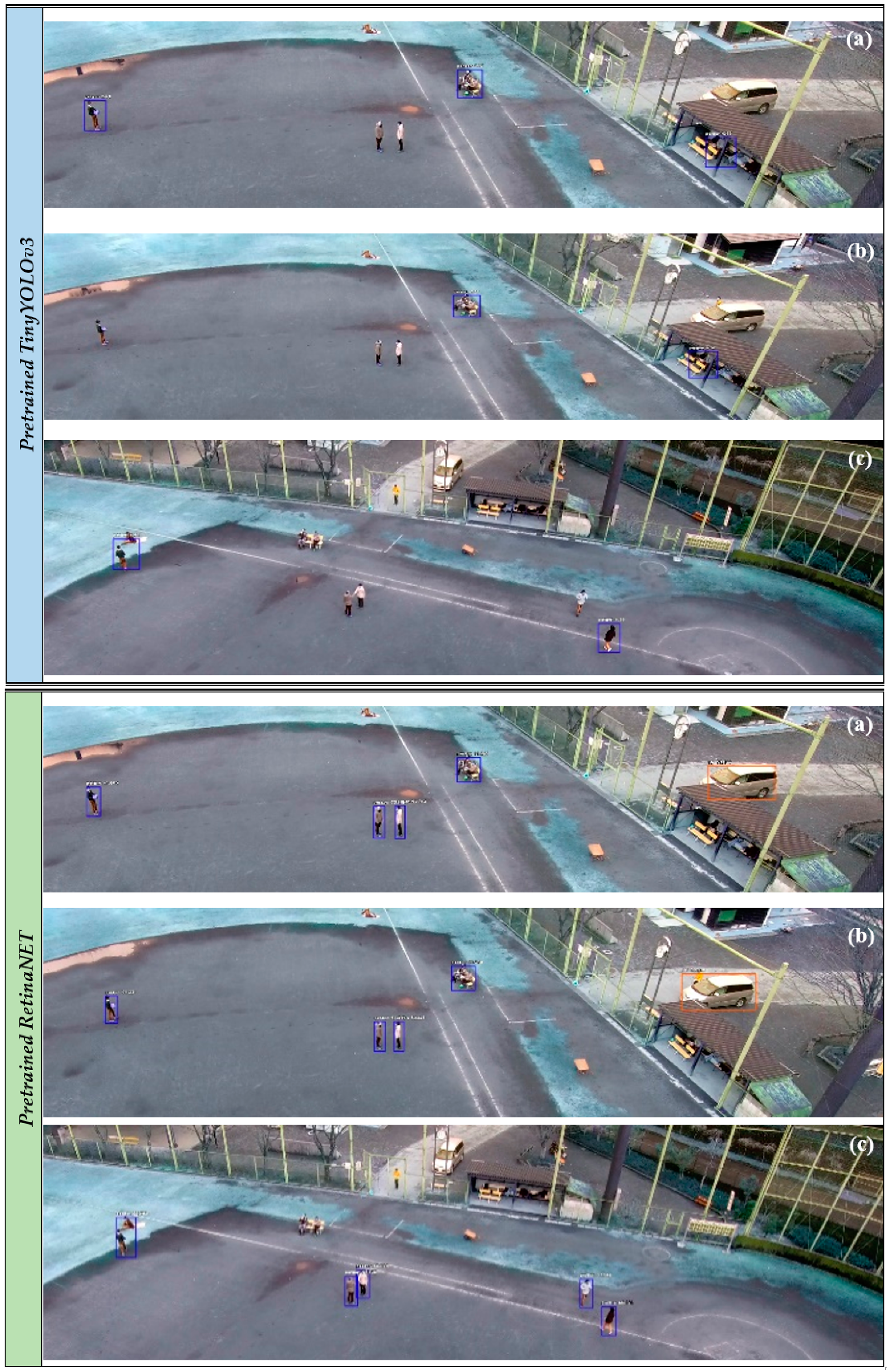
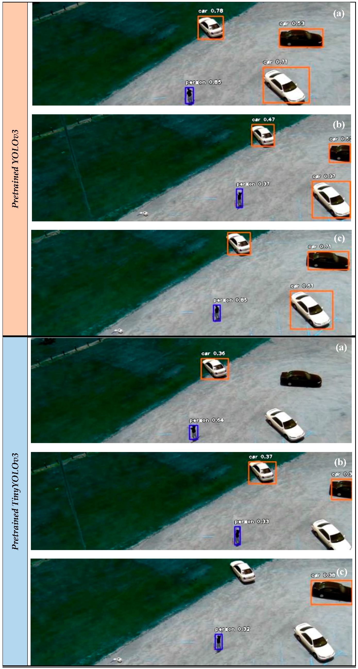
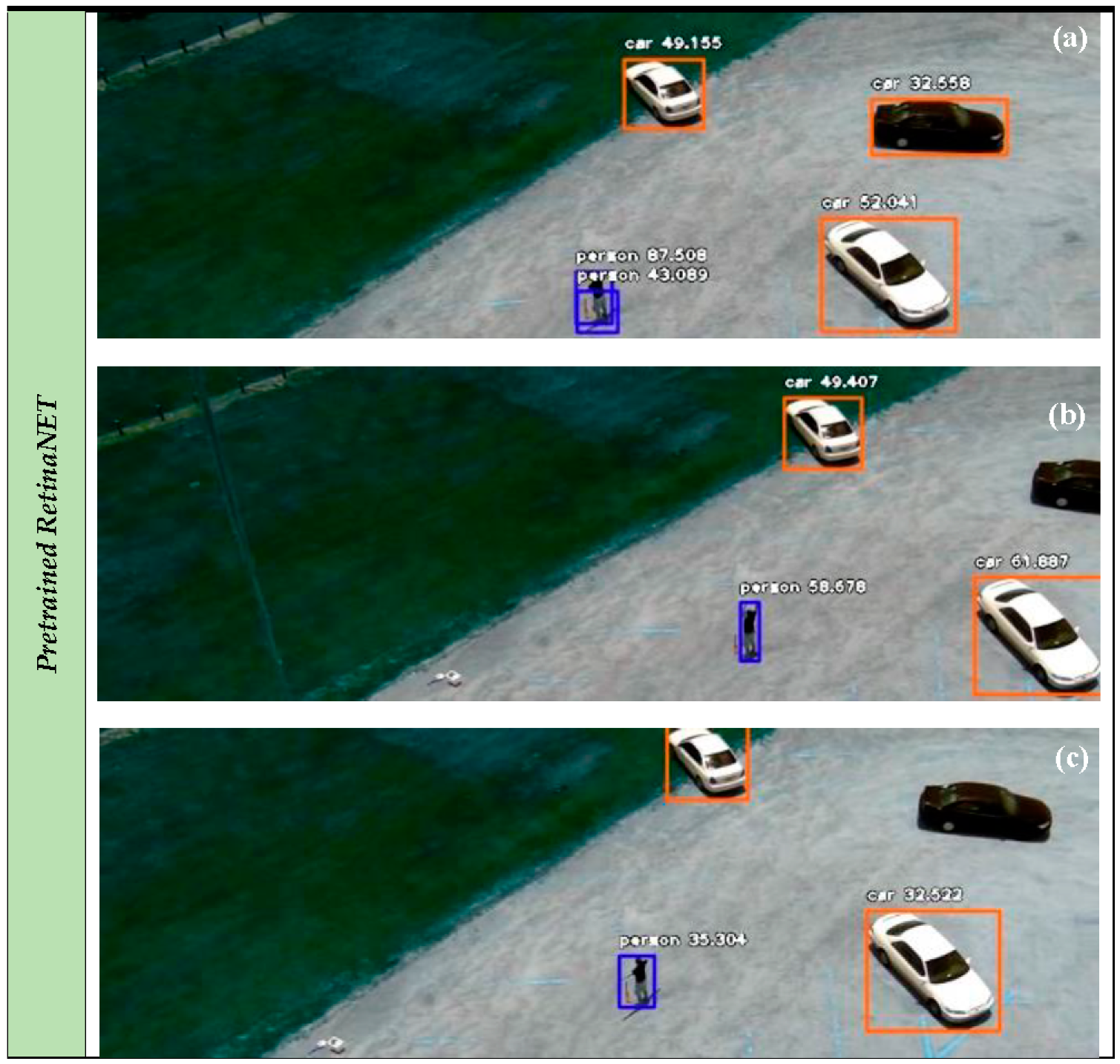
  • Define and set the object detector. The object detector is predefined among the: (i) pretrained YOLOv3 model, (ii) pretrained TinyYOLOv3 model, (iii) pretrained RetinaNET model, and (iv) custom YOLOv3 model. The process used to create and train a custom YOLOv3 model is provided in Section 6.3.2.
  • Read the deep learning weights of the defined object detector. The deep learning weights are in *.h5 format. In the case of the custom YOLOv3 model, a *.json file is also read that includes the new trained anchors.
  • Read the current frame of the camera streaming.
  • Apply the object detection model to the current frame and get the matrix object name, matrix probability, and matrix box point. The matrix object name includes the name of the class of each detected object (person or vehicle). The matrix probability includes the corresponding percentage probability where the detected object belongs to the assigned class. The matrix box point includes the bounding box (i.e., the top left and the bottom right image coordinates) of the detected object.
  • Overlay the rectangles of the matrix box point, the matrix object name and the matrix probability to the current frame of the camera streaming.
  • Calculate the object centroids (as image coordinates) of each bounding box from the matrix box point.
  • Import the object centroids to the localization module. The localization module is described in Section 7.
  • Export the matrix object name, the matrix box point and the WGS’84 coordinates (latitude, longitude) from the localization module of each detected object to the Message Broker (see Section 3.3).

6.2. Evaluation Metrics

For the quantitative assessment, three objective criteria were adopted according to the International Society for Photogrammetry and Remote Sensing (ISPRS) guidelines [58], namely completeness (CM), correctness (CR), and quality (Q) measures per object, given as:
Completeness = TP TP + FN ,   Correctness = TP TP + FP ,   Quality = TP TP + FP + FN
where TP, FP, and FN denote true positives, false positives, and false negatives, respectively. The TP entries are the objects that exist in the scene and thus were correctly detected. The FP entries are the objects that not exist in scene and thus were incorrectly detected. The FN entries are the objects that exist in the scene but were not detected.

6.3. Aerial Asset

6.3.1. Experiments with Pretrained Deep Learning Models

Figure 9 and Figure 10 depict the experimental results of the object detection process on the OKUTAMA and UCF-ARG video datasets employing the YOLOv3, TinyYOLOv3, and RetinaNET models, respectively. The objects classes are “Car” and “Person”. Assessing qualitatively the experimental results of the RGB video datasets (OKUTAMA and UCF-ARG), the YOLOv3 model achieved better performance compared with the other models. This is also verified from an indicative quantitative assessment provided in Table 2 for the first 30 frames of the video datasets.
The TinyYOLOv3 and RetinaNET missed some crucial information concerning the objects of interest. The results of the YOLOv3 are considered satisfactory (average Q in the two datasets about 70%) taking account that only pretrained weights were adopted. However, in some frames, the YOLOv3 missed some objects. It should be mentioned that the OKUTAMA and UCF-ARG datasets consist of aerial views of low UAV altitude. Applying the YOLOv3 model on the UAV123 dataset, the object detection results were insufficient due to its higher UAV altitude view. To achieve more stable and accurate results two approaches are recommended: (i) perform a new training process, which is discussed in detail in Section 6.3.2, and (ii) adopt a high optical zoom while the UAV camera sensor captures the scene in order to compensate the UAV altitude and the appearance of the objects.

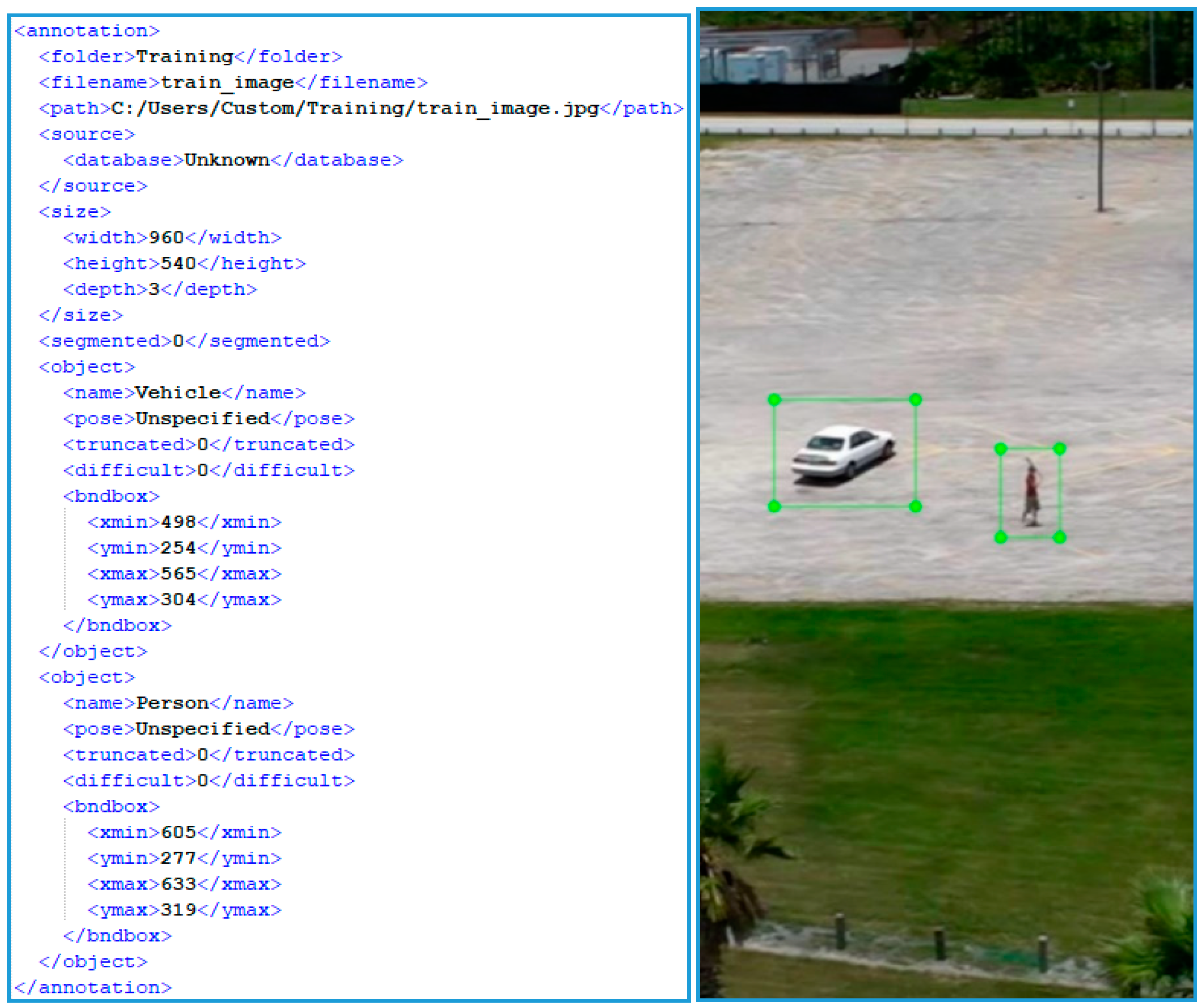
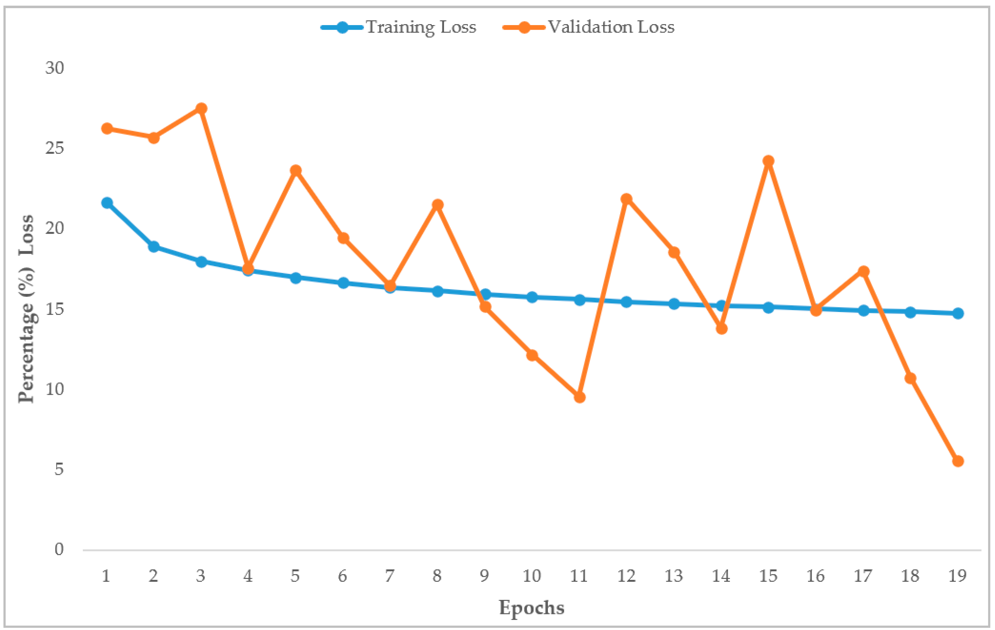
6.3.2. Experiments with Custom Deep Learning Model

To cover cases of higher UAV altitude view, a custom deep learning model is created. More specifically, the YOLOv3 is retrained applying a transfer learning scheme [59] exploiting the available pretrained YOLOv3 weights. The objects classes are “Vehicles” and “Persons”, where the class “Vehicles” incorporate both cars and trucks. In this context, a training process is carried out exploiting the 16 datasets described in Section 4. Twelve RGB and four thermal datasets are used. This unequal distribution in the used spectral datasets is justified because few free thermal datasets from UAVs, with pedestrians and vehicles, are available in the web. Each dataset is split into a training set and validation set. The corresponding percentages of the total images of each dataset is 80% for the training set and 20% for the validation set. In addition, the corresponding annotation files are created both for the training and validation set. The annotation file includes crucial information for the training and validation samples, such as the bounding box of each object class, the name of the class, etc. Figure 11, depicts a sample annotation file, where width, height, depth are the dimensions of the image, name is the object class, and xmin, ymin, xmax, ymax are the top left and the bottom right coordinates respectively of the object bounding box. At the end of the training process, new anchors and weights are created associated with the custom YOLOv3. Table 3 provides detailed information for the datasets used for the custom YOLOv3, such as the number of the total images and the number of the samples of each class. Figure 12 depicts the distribution of the samples in each class per dataset retrieving this information from the Table 3. The total number of samples of the class “Persons” is about the half of the number of samples of the class “Vehicles”. This is justified due to the greater number of available free and qualitative datasets with pedestrians; furthermore, in some datasets (e.g., such the VisDrone2019 dataset) the cars and the trucks were registered in the class “Vehicles”. The training process is not influenced from the difference between the numbers of the two classes. Nevertheless, the total count of the samples indicates an adequate training and validation set depicting a variety of scenes captured from several spectral sensors and perspectives, and with variable pixel resolution. Thus, a robust custom deep learning model is extracted with high generalization properties in videos and images from the training set.
Concerning the training process, the batch size was selected to be equal to four, and a GPU process was considered via a NVIDIA GeForce RTX 2080. The computational time of each epoch was 24 h. The training and validation loss percentages versus training epochs are presented in Figure 13. As is observed, the training process converges at a maximum of 19 epochs. This is mainly due to the fact that early stopping criteria are adopted to reduce the computational cost. The training loss was almost stabilized from the fifth epoch. In contrast, the validation loss presents fluctuations as the training process continued and the custom weights were adapted respectively. Finally, a validation loss = 5.5% and training loss = 14.7% were achieved in the 19th epoch. In addition, the evaluation metric mean Average Precision (mAP) was calculated using the following thresholds: (i) Intersection over Union (IoU): 50%, (ii) object probability: 30%, and (iii) Non-Maximum Suppression (NMS): 50%. The Average Precision (AP) for the two classes were Person: 0.4868 and Vehicle: 0.6652, in addition to mAP: 0.5760. The achieved mAP is considered satisfactory and equal to the initial proposed YOLOv3-320, YOLOv3-416, and YOLOv3-608 versions, indicating a robust custom YOLOv3 model. Figure 14 depicts object detection results in real time for real case scenarios utilizing an RGB camera and applying the custom YOLOv3 model.

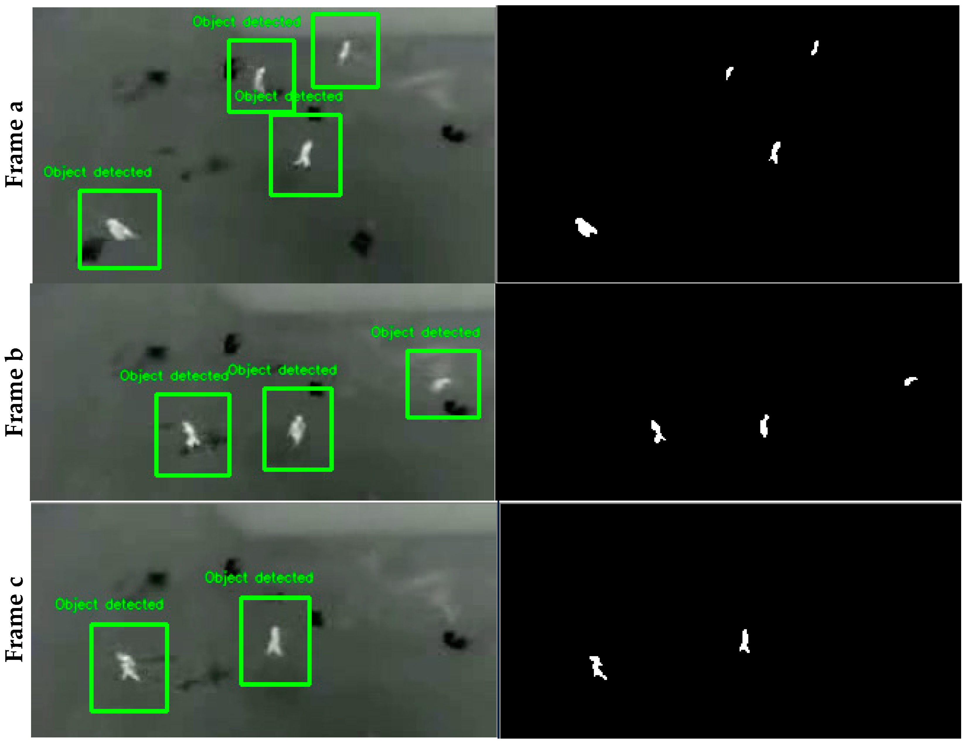
6.3.3. Experiments with OBIA

Figure 15 depicts the object detection results and the corresponding binary masks applying the OBIA technique on the LITIV2012 dataset. The values of the used parameters were:
(i)
color threshold = 170 pixels. Pixels with higher color values from this threshold correspond to the objects of interest of high temperature.
(ii)
dilation contour = 20 pixels. A dilation on the contours of the detected objects is performed to fill holes and to extract solid objects.
(iii)
minimum area = 10 pixels and maximum area = 30,000 pixels. Only the objects within this pixel area range are assigned as objects of interest.
The results from applying the OBIA technique on the thermal video dataset (LITIV2012 dataset) can be considered satisfactory because all of the objects were detected. Although the limitation of this technique is that should be applied to simple scenes, it is able to give a reliable position of an object of interest. For more complex cases such as the one depicted in the VIVID dataset, the OBIA technique will detect false positive entries associated with road lights and other objects with high temperature. Furthermore, another limitation is that the detected objects have no semantic information, i.e., they are not assigned to a specific class (e.g., persons). Similar to object tracking experiments, to extract a general overview for the performance of each deep learning model and the OBIA technique, an extended experimental analysis is required in terms of: (i) variable sensor cameras; (ii) variable pixel resolution; (iii) computational time; (iv) variable perspectives of the objects; and (v) variable datasets of complex scenes with occlusions, shadows, repetitive patterns.

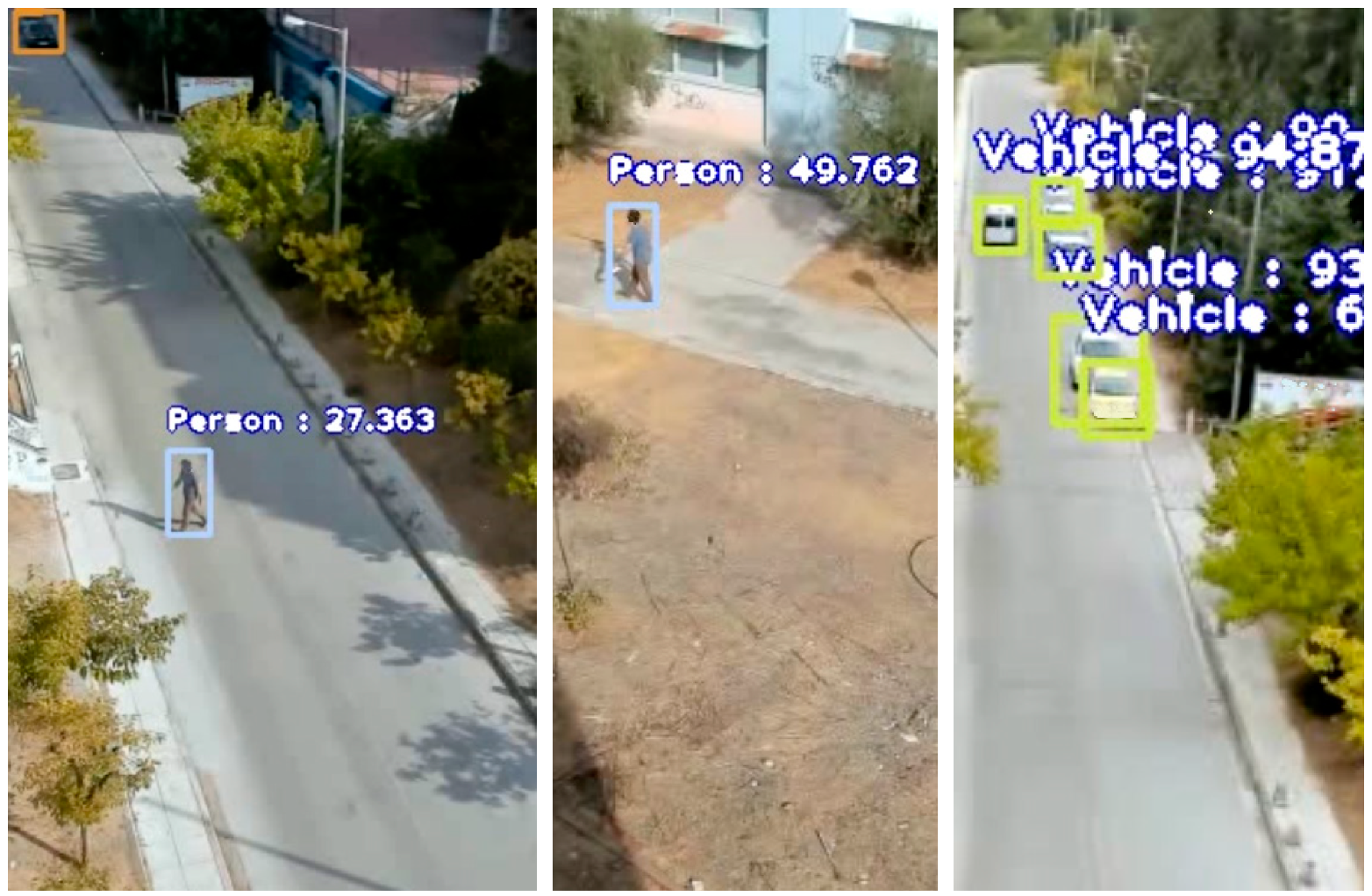
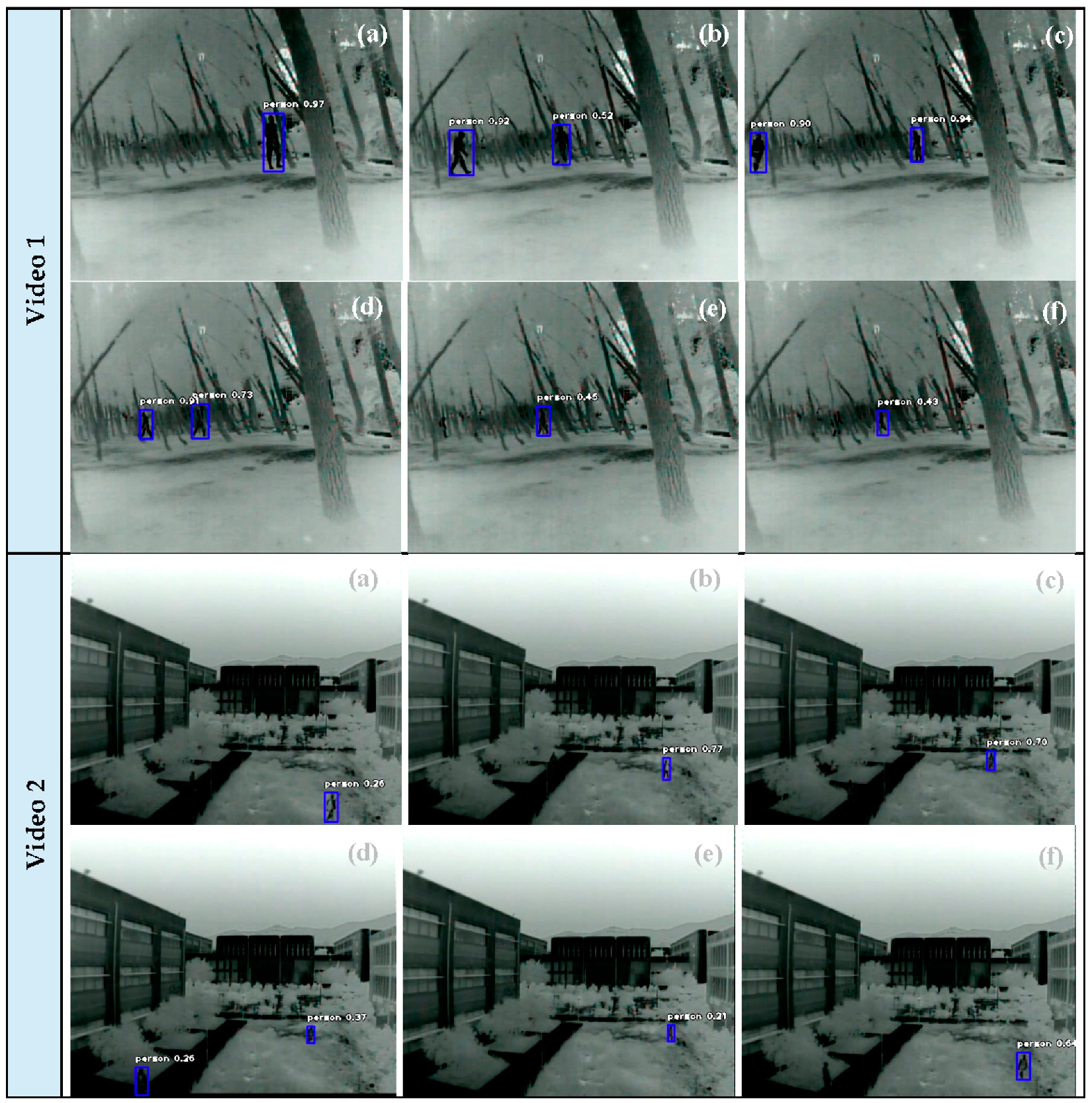
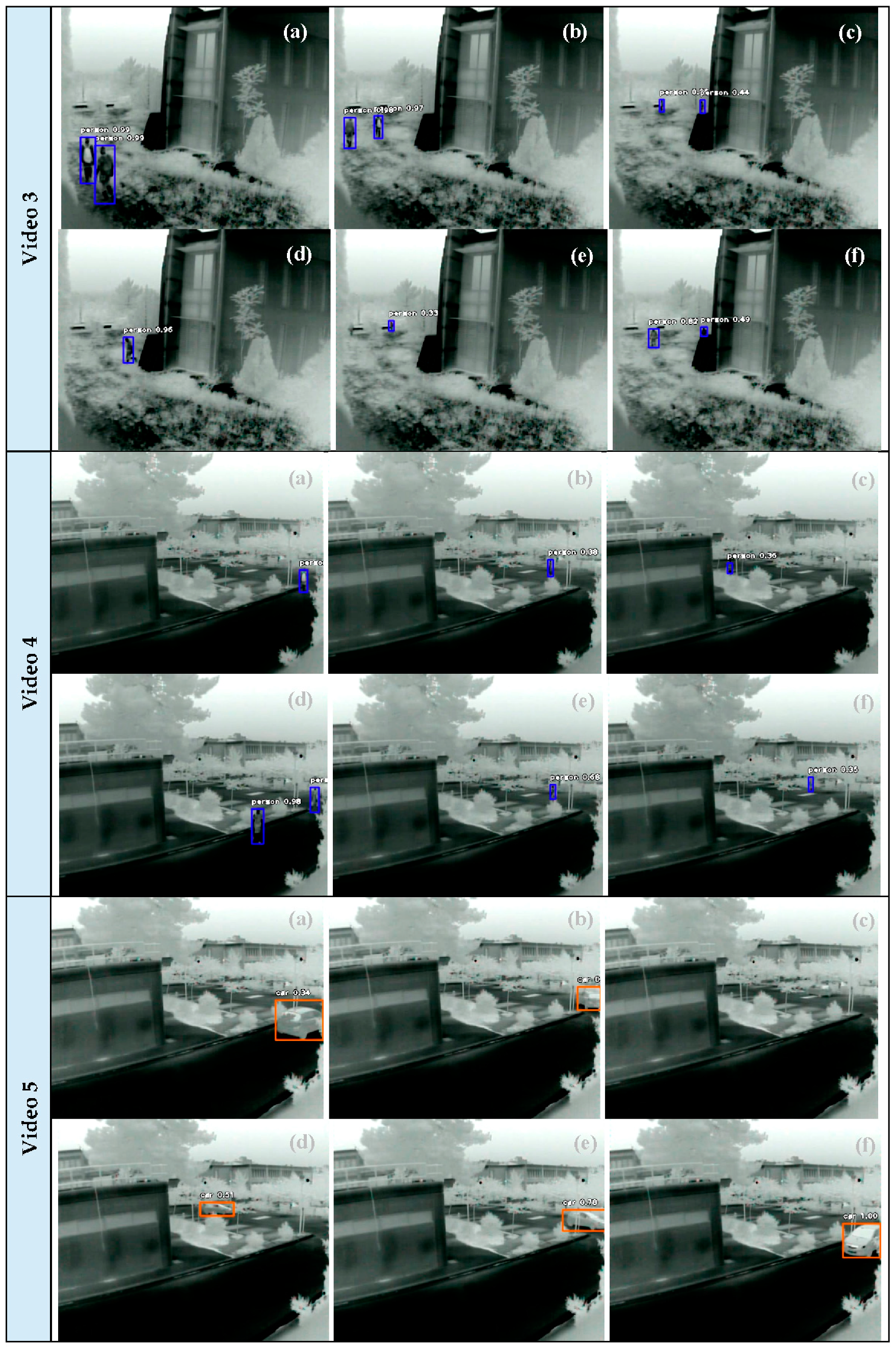
6.4. Terrestrial Asset

Experiments with Pretrained Deep Learning Models

Figure 16 depicts object detection results in real time case scenarios utilizing the thermal camera and applying the pretrained YOLOv3 model. Indicative quantitative assessment is provided in Table 4 for the corresponding videos. The thermal camera was installed in several positions and perspectives in parking space, park, and structure environment. According to the results, the pretrained YOLOv3 model achieved satisfactory results when the distance between the camera and object was lower than 40 m. This is mainly due to occlusions, similar thermal values between background and the objects, and the somewhat low resolution of the thermal camera. However, the achieved average rates for all the videos were CM = 75.5%, CR = 97.0%, and Q = 73.7%, indicating the appropriateness of the pretrained YOLOv3 model in thermal views.

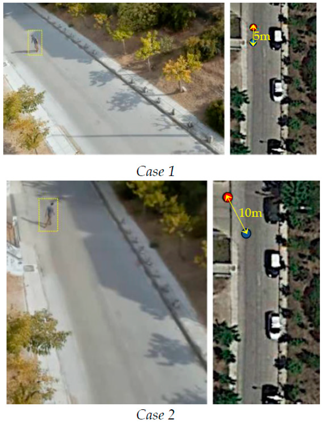
7. Localization, Speed and Heading

The calculation of the localization, speed, and heading of a tracked or a detected object is considered an important advantage of a UxV system compared to typical tracking or detection schemes. In this context, for instance, not only the UAV position is provided but also the ground real world coordinates (e.g., the WGS’84 coordinates) of the detected or tracked objects. By these means, a clearer view of the area of interest, and an enhanced scene understanding, is achieved, providing more accurate and additional information. Such information can be overlaid on several georeferenced maps, in addition to contributing to external systems with fusion modules through rule-based schemes in order to be correlated with other features.

7.1. Localization Module

The on-board localization module is responsible for calculating the ground real-world coordinates (i.e., the WGS’ 84 coordinates as latitude and longitude) of the detected objects or tracked object in real-world coordinates as the UAV is moving. This module is provided only for the UAV asset. To estimate these WGS’ 84 coordinates, linear features in terms of collinearity condition [60] are considered to express the relationship between pixel locations on the image plane and the corresponding 3D world coordinates on the ground. The module is based on the Python programming language using the math and pyproj libraries. In the following outline, the corresponding workflow of the localization module in each camera frame is described:
  • Import the object centroids from the object detection or object tracking module.
  • Import the turns yaw, pitch, roll of the gimbal.
  • Import the UAV position as WGS’ 84 coordinates.
  • Import the camera sensor parameters.
  • Calculate the distance from the UAV position and the projection image center in the real world via the turn pitch.
  • Transform the UAV position from WGS’ 84 to the UTM projection.
  • Transform the object centroids coordinates from the image plane to photogrammetric image center.
  • Calculate the real-world coordinates of the detected or tracked object in the UTM projection via the collinearity condition.
  • Transform the coordinates from UTM projection to WGS’84.
  • Export the UTM projection coordinates to the speed and heading module if the object tracking module is active. The speed and heading module is described in Section 7.2.
  • Export the WGS’84 coordinates to the object detection or object tracking module.

7.1.1. Collinearity Condition

The mathematical expression of the collinearity condition is described in the following. Figure 17 shows the collinearity condition in the 3D space. It is noticed that the collinearity condition in the 3D space is considered for aerial cases with nadir captures. Thus, position error at the objects in ground are imported for wide viewing angles that resemble terrestrial cases. However, to mitigate such cases of high pitch turns, a shift in the 3D space is adopted by considering the distance from the UAV position and the projection image center in the real world. The localization module considers the same assumptions, namely [61]:
-
We assume the earth is semi-flat between the aircraft and the target in the Field Of View (FOV), with a variance of less than a couple of meters.
-
We have at least 1 arcsecond post data for the digital elevation model (DEM).
-
We assume that the plumb-line (e.g., local gravity vector) is parallel to the geodetic normal of the ellipsoid. This will allow us to simply add/subtract DEM, ellipsoid, and geoid elevations.
-
We assume that we know the aircraft position to less than a few centimeters, and attitude to some immeasurable error.
-
We assume that we know the position of the camera and its orientation relative to the aircraft perfectly.
-
We assume that we do not have any timing errors between image frames, and position/attitude information.
Our localization module uses the camera’s intrinsic matrix and its lens distortion parameters, obtained through camera calibration (see Section 7.1.2), which were not considered in [61].
The collinearity condition expresses the basic relationship in which an object point and its image lies on a straight line passing through the perspective center. The general collinearity equation is expressed as follows:
[ x y c ] =   λ ·   R ω φ κ · [ Χ Χ ο Υ Υ ο Ζ Ζ ο ]
R =   R κ   R φ   R ω = [ r 11 r 12 r 13 r 21 r 22 r 23 r 31 r 32 r 33 ]
R = [ c o s φ c o s k c o s ω s i n κ + s i n ω s i n φ c o s κ s i n ω s i n κ c o s ω s i n φ c o s κ c o s φ c o s k c o s ω c o s κ s i n ω s i n φ s i n κ s i n ω c o s κ + c o s ω s i n φ s i n κ s i n φ s i n ω   c o s φ c o s ω c o s φ ]
The detailed collinearity condition taking consideration of all of the camera parameters is the following:
x = x o Δ x r Δ x d c · ( X X 0 ) · r 11 + ( Y Y 0 ) · r 12 + ( Z Z 0 ) · r 13 ( X X 0 ) · r 31 + ( Y Y 0 ) · r 32 + ( Z Z 0 ) · r 33 y = y o Δ y r Δ y d c · ( X X 0 ) · r 21 + ( Y Y 0 ) · r 22 + ( Z Z 0 ) · r 23 ( X X 0 ) · r 31 + ( Y Y 0 ) · r 32 + ( Z Z 0 ) · r 33
where:
-
x′, y′ are the centroid coordinates of the object of interest in the image plane converted from the image plane system to the photogrammetric system.
-
xo, yo are the coordinates of the principal point.
-
Δxr, Δyr are the corrections of the radial-symmetric lens distortion parameters.
-
Δxd, Δyd are the corrections of the decentering lens distortion parameters.
-
Rωφκ is the matrix with elements ri,j incorporating the turns in the 3D space of the image plane referred to the world’s system.
-
c is the focal length of the camera.
-
X0, Y0, Z0 are the coordinates of the image center in the 3D space. Such coordinates are provided from the UAV position (as latitude and longitude) converted from the WGS’ 84 coordinate system to the UTM.
-
X, Y, Z are the coordinates of the object of interest in the 3D space. Because a monocular vision system is considered, the Z value should be predefined. Thus, the Z value is set as the home UAV height altitude associated with the ground geometric height in WGS’ 84. Solving Equation (5) for the unknowns X and Y, the corresponding UTM coordinates are calculated. The final latitude and longitude coordinates of the object are calculated by converting the UTM coordinates to WGS’ 84.
Figure 18 shows two examples of the calculated positions of a tracked object superimposed on Google Earth. The blue point in Figure 18 indicates the real position of the object (according to Google Earth) and the red point indicates the corresponding calculated position of the object through the localization module. The perspective view parameters for the first case were height = 20 m, pitch turn = −35°, azimuth = 20°, and the perspective view parameters for the second case were height = 20 m, pitch turn = −45°, azimuth = 5°. The difference between the real position and the calculated position of the object was 5 and 10 m for case 1 and case 2, respectively. Such differences can be considered satisfactory for a monocular, on-board, and real-time system, and for emergency response applications. However, an extended experimental analysis is required for (i) pitch turns, (ii) azimuth, (iii) heights, (iv) multiple objects with reference positions measured by RTK stations, and (v) type of sensor, in order to evaluate the sensitivity of the localization module in several scenarios.

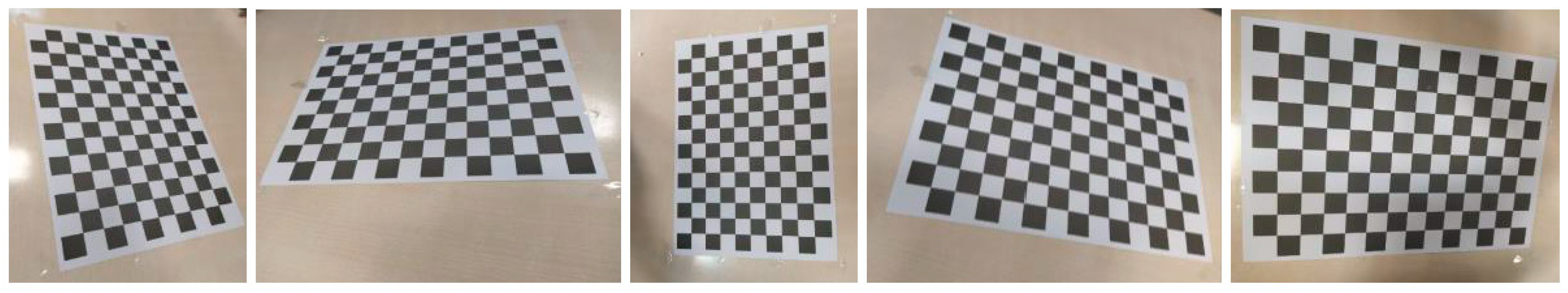
7.1.2. Camera Calibration

A calibration process [62] on the RGB camera is performed to acquire the precise intrinsic camera parameters. Such parameters feed the localization module to increase the object position accuracy and absorb lens distortions. The single assumption is that several images of a typical chess-board pattern (alternating dark and light squares), acquired with the same camera, are available. The algorithm then proceeds to extract object corner points, discard blunders, sort the valid nodes into pattern rows and columns, and finally calibrate the camera by bundle adjustment. Figure 19 shows five of the 13 chess-board pattern images that were totally collected in our laboratory. As a result of the final converged bundle adjustment, the calibrated intrinsic camera parameters are calculated: cx, cy the focal length in pixels in the x and y axis, respectively; xo,yo the coordinates of the principal point in pixels; ar the aspect ratio; sk the skewness; k1, k2 the coefficients of radial-symmetric lens distortion; and p1,p2 the coefficients of decentering lens distortion. The calibrated intrinsic RGB camera parameters are depicted in Figure 20 with the corresponding radial distortion curve. A calibration process for the thermal camera is one of the tasks for future work.

7.2. Speed and Heading

The speed and heading module is responsible for calculating the speed and the heading of the tracked object. This module is provided only for the UAV asset and the active tracking module. The module is based on the Python programming language using the math library. In the following outline, the corresponding workflow of the speed and heading module is described:
  • Import the object coordinates of the tracked object in UTM projection from the localization module with a time interval of 1 s.
  • Calculate the differences Dx = xBxA, Dy = yByA in the X axis and Y axis between the two position of timestamps A and B.
  • Calculate the azimuth of the vector between the two position points as azimuth = arctan (Dx/Dy).
  • Calculate the distance between the two position of timestamps as distance = sqrt (Dx2 + Dy2).
  • Export the speed, which is the distance in the time interval between the two position of timestamps, to the object tracking module.
  • Export the heading, which is the azimuth, to the object tracking module.

8. Conclusions and Future Work

This paper proposes an efficient and modular multipurpose situational awareness platform system, namely the Intelligent UxV Surveillance platform (INUS), that can support humans in analyzing video feeds and inform them promptly about detected and tracked objects in an area of interest. The system exploits novel UAV and terrestrial feature technologies, such as on-board processing, supports the integration of optical and thermal sensors, and applies robust and effective computer vision, image processing and machine learning techniques. In addition, a localization, speed, and heading module was designed to provide localized events. The information extracted from the localized events can provide not only an enhanced scene understanding but also contribute to external systems with fusion modules through rule-based schemes in order to be correlated with other features.
Concerning the tracking process, the Mosse and CSRT trackers appear to provide more stable results compared to the other trackers. Concerning the object detection process, several experiments were carried out applying deep learning pretrained and new custom-trained models in UAV and terrestrial videos. The pretrained YOLOv3 model achieved satisfactory results with a quality rate of 70–74% in complicated real case scenes both with RGB and thermal sensors. To cover cases of higher UAV altitude view, a custom deep learning model was created. Thus, the YOLOv3 was retrained by applying a transfer learning scheme. The experimental results achieved promising results, highlighting the potential and the functionality of the concept. As future work we intend to perform an extended experimental analysis for the object detection module in terms of: (i) variable sensor cameras; (ii) variable object classes; (iii) variable pixel resolution; (iv) computational time; (v) variable perspectives of the objects; and (vi) variable datasets of complex scenes with occlusions, shadows, repetitive patterns. In addition, we intend to perform an extended experimental analysis for the localization, speed, and heading modules with several (i) pitch turns, (ii) azimuths, (iii) UAV heights, (iv) multiple objects with reference positions measured by RTK stations, and (v) types of sensors.
Due to the modular design and the flexibility of the INUS platform, several extensions and enhancements can be made in future work for adaption to several applications. For instance, stereo cameras, hyperspectral cameras, or LIDAR sensors can be installed depending the scenario or user requirement needs. In addition, a fusion of the UAV and terrestrial assets may contribute to more stable and cross-checked detection and tracking events. Finally, new modules, e.g., motion detection and human pose estimation, can be designed to enhance the platform with several capabilities for a wide range of applications.

Author Contributions

Conceptualization, E.M., A.D. (Athanasios Douklias), L.K., F.M.; methodology, E.M., A.D. (Athanasios Douklias), A.D. (Aris Dadoukis), F.M., M.A.; software, E.M., A.D. (Athanasios Douklias), A.D. (Aris Dadoukis), K.V.; writing—review and editing, E.M., A.D. (Athanasios Douklias), A.D. (Aris Dadoukis), M.A., K.V., L.K., E.O.; validation, F.M., L.K., E.O.; supervision, F.M., L.K., E.O., A.A. All authors have read and agreed to the published version of the manuscript.

Funding

This research has received funding from the European Union’s Horizon 2020 research and innovation programme under grant agreement No 833881 of the Andromeda project.

Institutional Review Board Statement

Institute of Communication and Computer Systems has already submitted an ethical statement for this research in the context of the Andromeda project (under grant agreement No 833881) complying with H2020 Regulation (No 1291/2013 EU), particularly with Article 19 “Ethical Principles”.

Informed Consent Statement

Informed consent was obtained from all subjects involved in the study.

Data Availability Statement

Data sharing is not applicable to this article.

Acknowledgments

This work is a part of the Andromeda project. This project has received funding from the European Union’s Horizon 2020 research and innovation programme under grant agreement No 833881. Content reflects only the authors’ view and the Research Executive Agency (REA)/European Commission is not responsible for any use that may be made of the information it contains.

Conflicts of Interest

The authors declare no conflict of interest.

References

  1. Römer, H.; Kiefl, R.; Henkel, F.; Wenxi, C.; Nippold, R.; Kurz, F.; Kippnich, U. Using airborne remote sensing to increase situational awareness in civil protection and humanitarian relief—the importance of user involvement. ISPRS Int. Arch. Photogramm. Remote. Sens. Spat. Inf. Sci. 2016, XLI-B8, 1363–1370. [Google Scholar] [CrossRef] [Green Version]
  2. Rummukainen, L.; Oksama, L.; Timonen, J.; Vankka, J.; Lauri, R. Situation awareness requirements for a critical infrastructure monitoring operator. In Proceedings of the 2015 IEEE International Symposium on Technologies for Homeland Security (HST), Waltham, MA, USA, 14–16 April 2015; pp. 1–6. [Google Scholar] [CrossRef]
  3. Endsley, M.R. Toward a Theory of Situation Awareness in Dynamic Systems. Hum. Factors: J. Hum. Factors Ergon. Soc. 1995, 37, 32–64. [Google Scholar] [CrossRef]
  4. Geraldes, R.; Goncalves, A.; Lai, T.; Villerabel, M.; Deng, W.; Salta, A.; Nakayama, K.; Matsuo, Y.; Prendinger, H. UAV-Based Situational Awareness System Using Deep Learning. IEEE Access 2019, 7, 122583–122594. [Google Scholar] [CrossRef]
  5. Sharma, A.; Nazir, S.; Ernstsen, J. Situation awareness information requirements for maritime navigation: A goal directed task analysis. Saf. Sci. 2019, 120, 745–752. [Google Scholar] [CrossRef]
  6. Thombre, S.; Zhao, Z.; Ramm-Schmidt, H.; Garcia, J.M.V.; Malkamaki, T.; Nikolskiy, S.; Hammarberg, T.; Nuortie, H.; Bhuiyan, M.Z.H.; Särkkä, S.; et al. Sensors and AI Techniques for Situational Awareness in Autonomous Ships: A Review. IEEE Trans. Intell. Transp. Syst. 2020, 1–20. [Google Scholar] [CrossRef]
  7. Onwubiko, C. Designing Information Systems and Network Components for Situational Awareness. Available online: www.igi-global.com/chapter/designing-information-systems-network-components/62378 (accessed on 23 December 2020). [CrossRef] [Green Version]
  8. Nguyen, T.T.; Lim, C.P.; Nguyen, N.D.; Gordon-Brown, L.; Nahavandi, S. A Review of Situation Awareness Assessment Approaches in Aviation Environments. IEEE Syst. J. 2019, 13, 3590–3603. [Google Scholar] [CrossRef] [Green Version]
  9. Budiyono, A. Advances in Unmanned Aerial Vehicles Technologies. Chin. Sci. Bull. 2007, 52, 1–13. [Google Scholar]
  10. Valavanis, K.P. (Ed.) Advances in Unmanned Aerial Vehicles: State of the Art and the Road to Autonomy; Intelligent Systems, Control and Automation: Science and Engineering; Springer: Dordrecht, The Netherlands, 2007. [Google Scholar] [CrossRef]
  11. Li, B.; Fei, Z.; Zhang, Y. UAV Communications for 5G and Beyond: Recent Advances and Future Trends. IEEE Internet Things J. 2019, 6, 2241–2263. [Google Scholar] [CrossRef] [Green Version]
  12. Luo, W.; Xing, J.; Milan, A.; Zhang, X.; Liu, W.; Kim, T.-K. Multiple object tracking: A literature review. arXiv 2017, arXiv:14097618. [Google Scholar]
  13. Wang, Q.; Chen, F.; Xu, W.; Yang, M.-H. An experimental comparison of online object-tracking algorithms. In Wavelets and Sparsity XIV.; SPIE: Bellingham, WA, USA, 2011; Volume 8138, p. 81381A. [Google Scholar] [CrossRef] [Green Version]
  14. Mueller, M.; Sharma, G.; Smith, N.; Ghanem, B. Persistent Aerial Tracking system for UAVs. In Proceedings of the 2016 IEEE/RSJ International Conference on Intelligent Robots and Systems (IROS), Daejeon, Korea, 9–14 October 2016; pp. 1562–1569. [Google Scholar] [CrossRef]
  15. Qu, Z.; Lv, X.; Liu, J.; Jiang, L.; Liang, L.; Xie, W. Long-term reliable visual tracking with UAVs. In Proceedings of the 2017 IEEE International Conference on Systems, Man, and Cybernetics (SMC), Banff, AB, Canada, 5–8 October 2017; pp. 2000–2005. [Google Scholar] [CrossRef]
  16. Zhang, L.; Zhang, Z.; Xiong, H. Visual Pedestrian Tracking from a UAV Platform. In Proceedings of the 2017 2nd International Conference on Multimedia and Image Processing (ICMIP), Wuhan, China, 17–19 March 2017; pp. 196–200. [Google Scholar] [CrossRef]
  17. Zhao, Z.-Q.; Zheng, P.; Xu, S.-T.; Wu, X. Object Detection with Deep Learning: A Review. IEEE Trans. Neural Networks Learn. Syst. 2019, 30, 3212–3232. [Google Scholar] [CrossRef] [Green Version]
  18. Xu, Y.; Yu, G.; Wang, Y.; Wu, X.; Ma, Y. Car Detection from Low-Altitude UAV Imagery with the Faster R-CNN. Available online: https://www.hindawi.com/journals/jat/2017/2823617/ (accessed on 23 December 2020). [CrossRef] [Green Version]
  19. Xu, S.; Savvaris, A.; He, S.; Shin, H.-S.; Tsourdos, A. Real-time Implementation of YOLO+JPDA for Small Scale UAV Multiple Object Tracking. In Proceedings of the 2018 International Conference on Unmanned Aircraft Systems (ICUAS), Dallas, TX, USA, 12–15 June 2018; pp. 1336–1341. [Google Scholar] [CrossRef]
  20. Benjdira, B.; Khursheed, T.; Koubaa, A.; Ammar, A.; Ouni, K. Car Detection using Unmanned Aerial Vehicles: Comparison between Faster R-CNN and YOLOv3. In Proceedings of the 2019 1st International Conference on Unmanned Vehicle Systems-Oman (UVS), Muscat, Oman, 5–7 February 2019; pp. 1–6. [Google Scholar] [CrossRef] [Green Version]
  21. Zhu, P.; Wen, L.; Bian, X.; Ling, H.; Hu, Q. Vision Meets Drones: A Challenge. arXiv 2018, arXiv:180407437. [Google Scholar]
  22. Carrio, A.; Sampedro, C.; Rodriguez-Ramos, A.; Campoy, P. A Review of Deep Learning Methods and Applications for Unmanned Aerial Vehicles. Available online: https://www.hindawi.com/journals/js/2017/3296874/ (accessed on 23 December 2020). [CrossRef]
  23. Fraga-Lamas, P.; Ramos, L.; Mondéjar-Guerra, V.; Fernandez-Carames, T.M. A Review on IoT Deep Learning UAV Systems for Autonomous Obstacle Detection and Collision Avoidance. Remote. Sens. 2019, 11, 2144. [Google Scholar] [CrossRef] [Green Version]
  24. Cheng, G.; Han, J. A survey on object detection in optical remote sensing images. ISPRS J. Photogramm. Remote. Sens. 2016, 117, 11–28. [Google Scholar] [CrossRef] [Green Version]
  25. Ferreira, A.S. Workload and Situational Awareness management in UAV teams through interface modelling. Available online: https://www.semanticscholar.org/paper/Workload-and-Situational-Awareness-management-in-Ferreira/730c3085ea481256f7620ba7d3be0bfa9f33dd9d (accessed on 22 January 2021).
  26. Tijtgat, N.; Van Ranst, W.; Volckaert, B.; Goedemé, T.; De Turck, F. Embedded real-time object detection for a UAV warning system. In Proceedings of the 2017 IEEE International Conference on Computer Vision Workshops, ICCV Workshops 2017, Venice, Italy, 22–29 October 2017; pp. 2110–2118. [Google Scholar]
  27. Hadia, X.; Price, S.R.; Price, S.R.; Price, S.J.; Fairley, J.R. Object detection on aerial imagery to improve situational awareness for ground vehicles. In Artificial Intelligence and Machine Learning for Multi-Domain Operations Applications II; SPIE: Bellingham, WA, USA, 2020; Volume 11413, p. 114131J. [Google Scholar] [CrossRef]
  28. Bhattarai, M.; Ramon, M.M. A Deep Learning Framework for Detection of Targets in Thermal Images to Improve Firefighting. IEEE Access 2020, 8, 88308–88321. [Google Scholar] [CrossRef]
  29. Hossain, S.; Lee, D.-J. Deep Learning-Based Real-Time Multiple-Object Detection and Tracking from Aerial Imagery via a Flying Robot with GPU-Based Embedded Devices. Sensors 2019, 19, 3371. [Google Scholar] [CrossRef] [PubMed] [Green Version]
  30. Mazzia, V.; Khaliq, A.; Salvetti, F.; Chiaberge, M. Real-Time Apple Detection System Using Embedded Systems with Hardware Accelerators: An Edge AI Application. IEEE Access 2020, 8, 9102–9114. [Google Scholar] [CrossRef]
  31. Barekatain, M.; Marti, M.; Shih, H.-F.; Murray, S.; Nakayama, K.; Matsuo, Y.; Prendinger, H. Okutama-Action: An Aerial View Video Dataset for Concurrent Human Action Detection. In Proceedings of the 2017 IEEE Conference on Computer Vision and Pattern Recognition Workshops (CVPRW), Honolulu, HI, USA, 21–26 July 2017; pp. 2153–2160. [Google Scholar] [CrossRef] [Green Version]
  32. Mueller, M.; Smith, N.; Ghanem, B. A Benchmark and Simulator for UAV Tracking. In European Conference on Computer Vision; Springer: Cham, Switzerland, 2016; pp. 445–461. [Google Scholar]
  33. Nagendran, A.; Harper, D.; Shah, M. New System Performs Persistent Wide-Area Aerial Surveillance. 2010. Available online: http://spie.org/x41092.xml?ArticleID=x41092 (accessed on 28 January 2021).
  34. Bozcan, I.; Kayacan, E. AU-AIR: A Multi-modal Unmanned Aerial Vehicle Dataset for Low Altitude Traffic Surveillance. arXiv 2020, arXiv:200111737. [Google Scholar]
  35. Hsieh, M.-R.; Lin, Y.-L.; Hsu, W.H. Drone-Based Object Counting by Spatially Regularized Regional Proposal Network. arXiv 2017, arXiv:170705972. [Google Scholar]
  36. Du, D.; Qi, Y.; Yu, H.; Yang, Y.; Duan, K.; Li, G.; Zhang, W.; Huang, Q.; Tian, Q. The Unmanned Aerial Vehicle Benchmark: Object Detection and Tracking. arXiv 2018, arXiv:180400518. [Google Scholar]
  37. Tanner, F.; Colder, B.; Pullen, C.; Heagy, D.; Eppolito, M.; Carlan, V.; Oertel, C.; Sallee, P. Overhead imagery research data set—An annotated data library & tools to aid in the development of computer vision algorithms. In 2009 IEEE Applied Imagery Pattern Recognition Workshop (AIPR 2009); IEEE: Piscataway, NJ, USA, 2009; pp. 1–8. [Google Scholar] [CrossRef]
  38. GitHub. Aerial-Car-Dataset. Available online: https://github.com/jekhor/aerial-cars-dataset (accessed on 23 December 2020).
  39. Davis, J.W.; Keck, M.A. A Two-Stage Template Approach to Person Detection in Thermal Imagery. In Proceedings of the Seventh IEEE Workshops on Applications of Computer Vision (WACV/MOTION’05), Breckenridge, CO, USA, 5–7 January 2005; Volume 1, pp. 364–369. [Google Scholar] [CrossRef]
  40. Kumar, S.V.A.; Yaghoubi, E.; Das, A.; Harish, B.S.; Proenca, H. The P-DESTRE: A Fully Annotated Dataset for Pedestrian Detection, Tracking, and Short/Long-Term Re-Identification From Aerial Devices. IEEE Trans. Inf. Forensics Secur. 2021, 16, 1696–1708. [Google Scholar] [CrossRef]
  41. Collins, R.T.; Hebert, M.; Yalcin, H.; Tolliver, D.; Leordeanu, M.; Zhou, X.; Teh, S.K. VIVID Tracking Evaluation Web Site. Available online: http://vision.cse.psu.edu/data/vividEval/ (accessed on 23 December 2020).
  42. Torabi, A.; Massé, G.; Bilodeau, G.-A. An iterative integrated framework for thermal–visible image registration, sensor fusion, and people tracking for video surveillance applications. Comput. Vis. Image Underst. 2012, 116, 210–221. [Google Scholar] [CrossRef]
  43. Thermal Infrared Dataset. Available online: https://www.google.com/search?client=firefox-b-d&q=ir+iricra2014+%E2%80%93+ASL+Datasets (accessed on 23 December 2020).
  44. Kalal, Z.; Mikolajczyk, K.; Matas, J. Forward-Backward Error: Automatic Detection of Tracking Failures. In Proceedings of the 20th International Conference on Pattern Recognition, Istanbul, Turkey, 23–26 August 2010; pp. 2756–2759. [Google Scholar]
  45. Grabner, H.; Bischof, H. Real-Time Tracking via On-line Boosting. In Proceedings of the British Machine Vision Conference, Edinburgh, UK, 4–7 September 2006. [Google Scholar]
  46. Held, D.; Thrun, S.; Savarese, S. Learning to Track at 100 FPS with Deep Regression Networks. In Computer Vision—ECCV 2016; Lecture Notes in Computer Science; Leibe, B., Matas, J., Sebe, N., Welling, M., Eds.; Springer: Cham, Switzerland, 2016; pp. 749–765. [Google Scholar] [CrossRef] [Green Version]
  47. Bolme, D.S.; Beveridge, J.R.; Draper, B.A.; Lui, Y.M. Visual object tracking using adaptive correlation filters. In Proceedings of the 2010 IEEE Computer Society Conference on Computer Vision and Pattern Recognition, San Francisco, CA, USA, 13–18 June 2010; pp. 2544–2550. [Google Scholar] [CrossRef]
  48. Lukežič, A.; Vojir, T.; Zajc, L.Č.; Matas, J.; Kristan, M. Discriminative Correlation Filter Tracker with Channel and Spatial Reliability. Int. J. Comput. Vis. 2018, 126, 671–688. [Google Scholar] [CrossRef] [Green Version]
  49. Kalal, Z.; Mikolajczyk, K.; Matas, J. Face-TLD: Tracking-Learning-Detection applied to faces. In Proceedings of the IEEE International Conference on Image Processing, Hong Kong, China, 12–15 September 2010; pp. 3789–3792. [Google Scholar] [CrossRef] [Green Version]
  50. Cai, C.; Liang, X.; Wang, B.; Cui, Y.; Yan, Y. A Target Tracking Method Based on KCF for Omnidirectional Vision. In Proceedings of the 37th Chinese Control Conference (CCC), Wuhan, China, 25–27 July 2018; pp. 2674–2679. [Google Scholar] [CrossRef]
  51. Babenko, B.; Yang, M.-H.; Belongie, S. Visual tracking with online Multiple Instance Learning. In Proceedings of the 2009 IEEE Conference on Computer Vision and Pattern Recognition, Miami, FL, USA, 20–25 June 2009; pp. 983–990. [Google Scholar] [CrossRef]
  52. Redmon, J.; Farhadi, A. YOLOv3: An Incremental Improvement. arXiv 2018, arXiv:180402767. [Google Scholar]
  53. Yi, Z.; Shen, Y.; Jun, Z. An improved tiny-yolov3 pedestrian detection algorithm. Optik 2019, 183, 17–23. [Google Scholar] [CrossRef]
  54. Lin, T.-Y.; Goyal, P.; Girshick, R.B.; He, K.; Dollar, P. Focal Loss for Dense Object Detection. arXiv 2018, arXiv:170802002. [Google Scholar] [CrossRef] [Green Version]
  55. Johnson, J.M.; Khoshgoftaar, T.M. Survey on deep learning with class imbalance. J. Big Data 2019, 6, 27. [Google Scholar] [CrossRef]
  56. Wang, Y.; Wang, C.; Zhang, H.; Dong, Y.; Wei, S. Automatic Ship Detection Based on RetinaNet Using Multi-Resolution Gaofen-3 Imagery. Remote. Sens. 2019, 11, 531. [Google Scholar] [CrossRef] [Green Version]
  57. Lin, T.Y.; Maire, M.; Belongie, S.; Hays, J.; Perona, P.; Ramanan, D.; Dollár, P.; Zitnick, C.L. Microsoft COCO: Common objects in context. In Computer Vision—ECCV 2014; Lecture Notes in Computer Science; Fleet, D., Pajdla, T., Schiele, B., Tuytelaars, T., Eds.; Springer: Cham, Swizerland, 2014; pp. 740–755. [Google Scholar] [CrossRef] [Green Version]
  58. Rottensteiner, F.; Sohn, G.; Gerke, M.; Wegner, J.D. ISPRS Test Project on Urban Classification and 3D Building Reconstruction Results. Available online: http://www2.isprs.org/tl_files/isprs/wg34/docs/ComplexScenes_revision_v4.pdf (accessed on 28 January 2021).
  59. Kaya, A.; Keceli, A.S.; Catal, C.; Yalic, H.Y.; Temucin, H.; Tekinerdogan, B. Analysis of transfer learning for deep neural network based plant classification models. Comput. Electron. Agric. 2019, 158, 20–29. [Google Scholar] [CrossRef]
  60. El-Ashmawy, K.L.A. A comparison study between collinearity condition, coplanarity condition, and direct linear transformation (DLT) method for camera exterior orientation parameters determination. Geodesy Cartogr. 2015, 41, 66–73. [Google Scholar] [CrossRef] [Green Version]
  61. Johnston, M.G. Ground Object Geo-Location using UAV Video Camera. In Proceedings of the 2006 IEEE/AIAA 25TH Digital Avionics Systems Conference, Portland, OR, USA, 15–18 October 2006; pp. 1–7. [Google Scholar] [CrossRef]
  62. Douskos, V.; Grammatikopoulos, L.; Kalisperakis, I.; Karras, G.; Petsa, E. Fauccal: An Open Source Toolbox for Fully Automatic Camera Calibration. Available online: http://portal.survey.ntua.gr/main/labs/photo/staff/gkarras/Karras_Cipa_09b.pdf (accessed on 23 December 2020).
Figure 1. The proposed situational awareness system, namely the INUS platform.
Computation 09 00012 g001
Figure 2. Basic hardware modules of the system.
Computation 09 00012 g002
Figure 3. Example snapshot of the User Interface of the intelligence officer’s workstation on the OKUTAMA dataset.
Computation 09 00012 g003
Figure 4. Workflow of the object tracking module.
Computation 09 00012 g004
Figure 5. Processed frames as the time goes on (frames (ae)) during a multiple car (three objects) tracking process on the UAV123 dataset.
Computation 09 00012 g005
Figure 6. Processed frames as the time progresses (frames (ag)) during a multiple person (two objects) tracking process on the OKUTAMA dataset.
Computation 09 00012 g006
Figure 7. Processed frames as the time progresses (frames (ae)) during a multiple car (two objects) tracking process on the VIVID dataset.
Computation 09 00012 g007
Figure 8. Processed frames as the time progresses (frames (ae)) during a multiple person (two objects) tracking process on the LITIV2012 dataset.
Computation 09 00012 g008
Figure 9. Object detection results (persons in blue rectangles and cars in orange rectangles) as the time goes on (frames (ac)) on the OKUTAMA dataset and applying several deep learning schemes.
Computation 09 00012 g009aComputation 09 00012 g009b
Figure 10. Object detection results (persons in blue rectangles and cars in orange rectangles) as time progresses (frames (ac)) on the UCF-ARG dataset and applying several pretrained deep learning schemes.
Computation 09 00012 g010aComputation 09 00012 g010b
Figure 11. Left: annotation file; right: the corresponding image subset with the bounding boxes of each sample object (green rectangles).
Computation 09 00012 g011
Figure 12. Distribution of the samples in each class per dataset used for the training and validation sets.
Computation 09 00012 g012
Figure 13. Training and validation loss percentages versus training epochs for the custom YOLOv3 model.
Computation 09 00012 g013
Figure 14. Object detection results (persons in cyan and car in orange/yellow rectangles) applying the custom YOLOv3 model in real case videos.
Computation 09 00012 g014
Figure 15. Left column: object detection results (green rectangles) as time progresses (frames (ac)) on the LITIV2012 dataset and applying the OBIA technique. Right column: the corresponding binary masks associated with the selected color and area thresholds.
Computation 09 00012 g015
Figure 16. Object detection results (persons in blue rectangles and cars in orange rectangles) for the terrestrial asset using the thermal camera as time progresses (frames (af)).
Computation 09 00012 g016aComputation 09 00012 g016b
Figure 17. Collinearity condition in the 3D space.
Computation 09 00012 g017
Figure 18. Examples of the calculated positions of a tracked object superimposed on Google Earth. The blue point indicates the real position of the object and the red point indicates the corresponding calculated position of the object through the localization module.
Computation 09 00012 g018
Figure 19. Sample chess-board pattern images from the RGB camera that collected in our laboratory.
Computation 09 00012 g019
Figure 20. Left: calibrated radial distortion curve. Right: calibrated intrinsic RGB camera parameters.
Computation 09 00012 g020
Table 1. Views from each free available video datasets.
DatasetType of SensorView
OKUTAMARGB Computation 09 00012 i001 Computation 09 00012 i002
UAV123RGB Computation 09 00012 i003 Computation 09 00012 i004
UCF-ARGRGB Computation 09 00012 i005 Computation 09 00012 i006
VisDrone2019RGB Computation 09 00012 i007 Computation 09 00012 i008
AU-AIRRGB Computation 09 00012 i009 Computation 09 00012 i010
CARPKRGB Computation 09 00012 i011 Computation 09 00012 i012
PUCPRRGB Computation 09 00012 i013 Computation 09 00012 i014
UAVDTRGB Computation 09 00012 i015 Computation 09 00012 i016
OIRDSRGB Computation 09 00012 i017 Computation 09 00012 i018 Computation 09 00012 i019
JEKHORRGB Computation 09 00012 i020 Computation 09 00012 i021
OTCBVS-RGBRGB Computation 09 00012 i022 Computation 09 00012 i023
P-DESTRERGB Computation 09 00012 i024 Computation 09 00012 i025
VIVIDThermal Computation 09 00012 i026 Computation 09 00012 i027 Computation 09 00012 i028
LITIV2012Thermal Computation 09 00012 i029 Computation 09 00012 i030
OTCBVS-
THERMAL
Thermal Computation 09 00012 i031 Computation 09 00012 i032
IRICRAThermal Computation 09 00012 i033 Computation 09 00012 i034
Table 2. Quantitative object detection results for the first 30 frames of the OKUTAMA and UCF-ARG datasets.
OKUTAMA DatasetUCF-ARG Dataset
Pretrained Deep Learning ModelCM (%)CR (%)Q (%)CM (%)CR (%)Q (%)
YOLOv360.0100.060.079.2100.079.2
TinyYOLOv333.3100.033.322.581.821.4
RetinaNET68.189.463.070.895.568.5
Table 3. Detailed information for the datasets used for the custom YOLOv3.
DatasetNumber of Total ImagesNumber of Samples of the Class “Vehicle”Number of Samples of the Class “Person”
OKUTAMA4128-23,749
UAV1237952888289
UCF-ARG100730211024
VisDrone201934,061845,686406,896
AU-AIR32,713125,4265158
CARPK144889,774-
PUCPR12016,916-
UAVDT40,403763,817-
OIRDS4281644-
JEKHOR26270-
OTCBVS-RGB252427
P-DESTRE20,635-292,003
VIVID239875-
LITIV2012143-429
OTCBVS-
THERMAL
659992034
IRICRA3237-5747
Total count140,0671,850,440737,356
Table 4. Quantitative object detection results for terrestrial asset using the thermal camera and applying the pretrained YOLOv3 model.
VideoCM (%)CR (%)Q (%)
178.392.173.4
258.2100.058.2
395.0100.095.0
474.592.370.3
571.4100.071.4
Publisher’s Note: MDPI stays neutral with regard to jurisdictional claims in published maps and institutional affiliations.

