1. Introduction
The aim of the research is to investigate the behavior of a wind turbine’s single-stage planetary gearbox with several types of defects, such as pitting and tooth-root cracks. In wind turbines, gearboxes are among the components needing the most maintenance with a Mean Time To Failure (MTTF) of around five years, with an estimated lifetime of the machine of around 20 years [
1]. As the replacement of this component is very time-consuming and costly, the lifetime of this component might be increased by scheduled maintenance.
Given the behavior of the gearbox in the presence of damage, it might be useful to set up a sensor-based approach to monitor the conditions of the transmission and prevent and detect progressive damage. This can be based on stress/strain, temperature, and vibrations, etc. In any case, to detect the presence of the damage and, possibly, to determine its severity, type and position, the behavior of the system should be known. In this regard, data can be obtained from experimental measurements (for wind turbine gearboxes, such measurements and tests could be difficult and/or expensive), or from theoretical calculations.
Experimental-based works dealing with vibration measurements were proposed by several authors. Zhao et al. [
2] studied the effects of the damage on gears and bearings. Cao et al. [
3] studied the effects of damage with non-contact techniques. Kien et al. studied the effects of the presence of root cracks on plastic gears by means of neural networks [
4]. Ümütlü et al. studied the surface fatigue damage on worm gears [
5]. Huang, proposed a computational-based approach [
6]. A similar work based on cyclostationary analysis was presented by Mauricio et al. [
7] and by Sun et al. [
8].
Previous studies on high planetary transmissions (wind turbine gearboxes) were performed by the NREL (National Renewable Energy Laboratory—USA) using Transmission3D. Jason Louis Austin [
9] modelled an entire multi-stage transmission. Based on a test rig owned by the NREL, the model was validated with the data obtained experimentally.
Furthermore, Yi Guo et al. [
10] studied the load sharing in a three-point mounted wind turbine gearbox. This study was performed on a 750 kW gearbox test rig and simulated with Transmission3D as well as with RomaxWind to evaluate the differences between the approaches implemented in two software programs and compared to the real conditions. Both approaches reported some discrepancies from the measured results, but the overall trend was well captured. Kahraman et al. [
11], evaluated the influence of the rim gear size of the annulus on the strains. The predicted values were compared with the experimental ones. The outcomes of the study were promising even if, for certain ring gear thicknesses, the results overestimate the measured one. Further experiments on the effect of pits are performed experimentally by Yongzhi Qu et al. [
12] using fiber Bragg gratins and piezoelectric strain sensors placed near the root of the tooth. The outcomes of this research pointed out the feasibility of this type of sensing technology to spot differences in strain between damaged and undamaged gear flanks. Furthermore, Yongzhi Qu et al. demonstrated how strain sensors could be applied near the root of the tooth without affecting the proper working of the transmission.
Other authors use the vibrational response of the gearboxes as a trigger for detecting damage. In this regard, Concli et al. [
13] proposed a model of a back-to-back test rig and of a planetary gearbox [
14] based on the same hybrid Finite Element (FE)—the analytical approach used in this paper. The comparison of the vibrational spectra predicted, and the experimental measurements performed at Politecnico di Milano, have fully validated the approach. The error in terms of exited frequencies in the presence of damage was less than 14% for the back-to-back test rig and less than 5% for the planetary gearbox.
Other examples of numerical studies based on FEM optimization were presented by Karban et al. [
15].
In this paper, a previously developed model for vibrational characterization was extended to the prediction of the stress/strain states in the whole gearbox both for the healthy and the damaged conditions in which critical zones were identified. The approach (implemented within Transmission3D) is specifically developed to simulate mechanical gearboxes in all their components, including bearings (with all the rolling elements), the housing, shafts, and gears. Several simulations were performed modelling the healthy as well as the damaged configurations. The simulations without defects are performed to evaluate the nominal stress state of the different components. The types of damage applied to the model are pits and tooth root cracks.
The assessment of critical points was made by evaluating the zones subjected to stress variations in the presence of defects. The study of the behavior of the system in the presence of damage was thus evaluated with an innovative hybrid numerical–analytical approach.
Eventually, the results obtained might be used to develop a structural-health monitoring strategy to define where to place strain sensors on the transmission to be able to detect the presence and properties of defects present in the real transmission avoiding further catastrophic failures. The software capability to model the entire gearbox allows, for instance, to evaluate the distortions and the real load patterns. In the presence of defects, this type of analysis is fundamental to better characterize the entire gearbox. Hamand et al. [
16] and Haastrup et al. [
17] studied the stress and deflections induced by the presence of a defect by means of FE analysis. Hamand et al. identified the parameters influenced by damages. Lin et al. [
18] studied the eigenfrequencies and modal shape of a planetary gearbox by means of analytical methods. Drive [
19] studied the load sharing between the gears and teeth in faulty gearboxes.
2. Materials and Methods
The modelling of the above-mentioned planetary gearbox takes advantage of an innovative hybrid numerical–analytical approach implemented in the Transmission3D environment. The approach has been specifically developed to perform simulations of entire transmissions with a small computational effort. All the internal components of the system, including gears, bearings (with all the rolling elements), shafts, and housing, are modelled without simplifications. In this way, the response of the system to a source of excitation is more accurate. The approach uses a traditional FE solver to describe the macroscopic deflection of the components. The local deformations in the contacts between bodies (i.e., gear teeth, rolling elements, and races in bearings, etc.) are solved based on the Hertzian theory. In this way, a mesh refinement is not necessary to ensure convergence. For such a complex system, considering that the position of the contact and the number of engaging surfaces is variable during its operation, each gear flank should be filtered through mesh with a very fine grid with a traditional FEM (Finite Element Method) approach. On the other hand, the hybrid approach presented in this paper solves a relatively coarse grid in addition to an additional analytical equation for each active contact. Therefore, the total number of equations to be solved is significantly reduced (and therefore the computational effort) without losing accuracy or need to introduce simplifications.
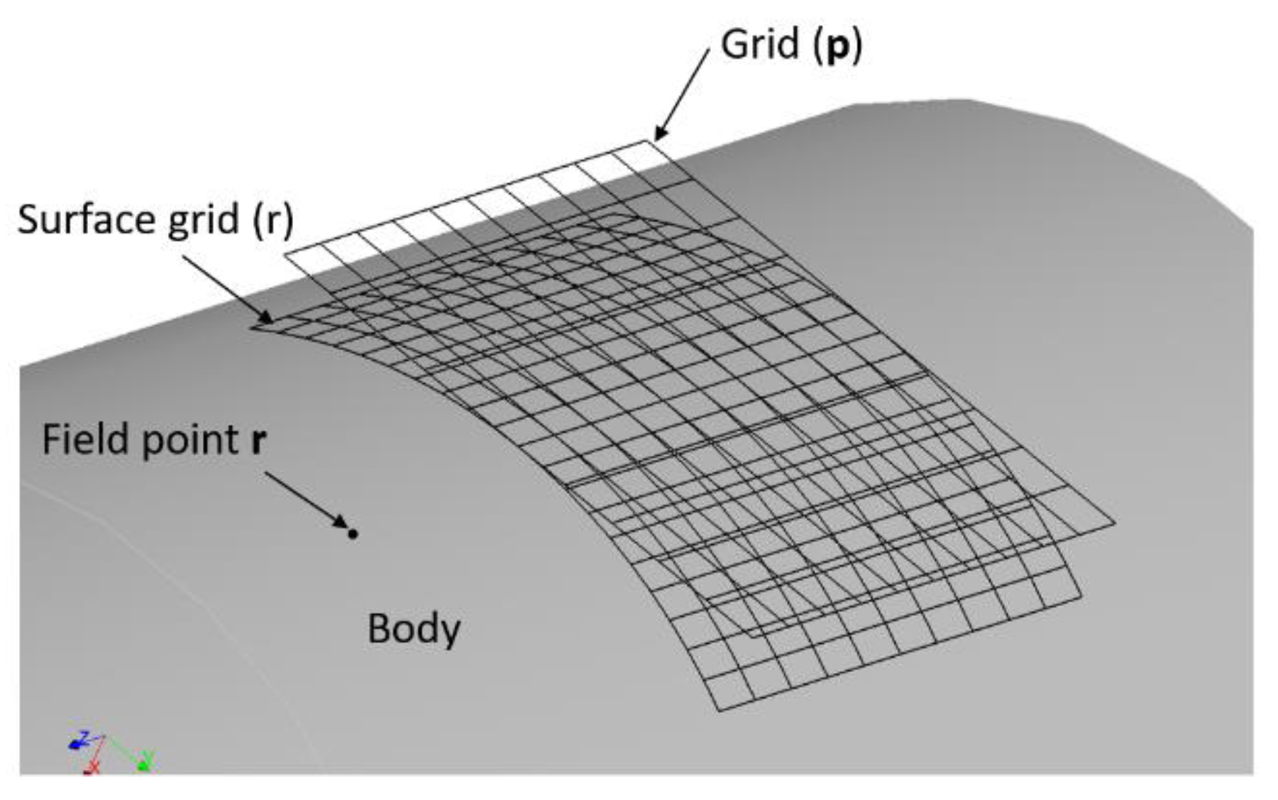
The points at which the individual contacting surfaces are closest to each other before the application of the load are computed first [
20]. After that, the surfaces normal are identified and the size of the contact zone can be estimated using the Hertzian equations. At this point, a computational grid (larger than the predicted Hertzian contact ellipse) is laid out around each principal contact point (
Figure 1) and projected on both body surfaces. The computed contact pressures are not very sensitive to the size of the grid.
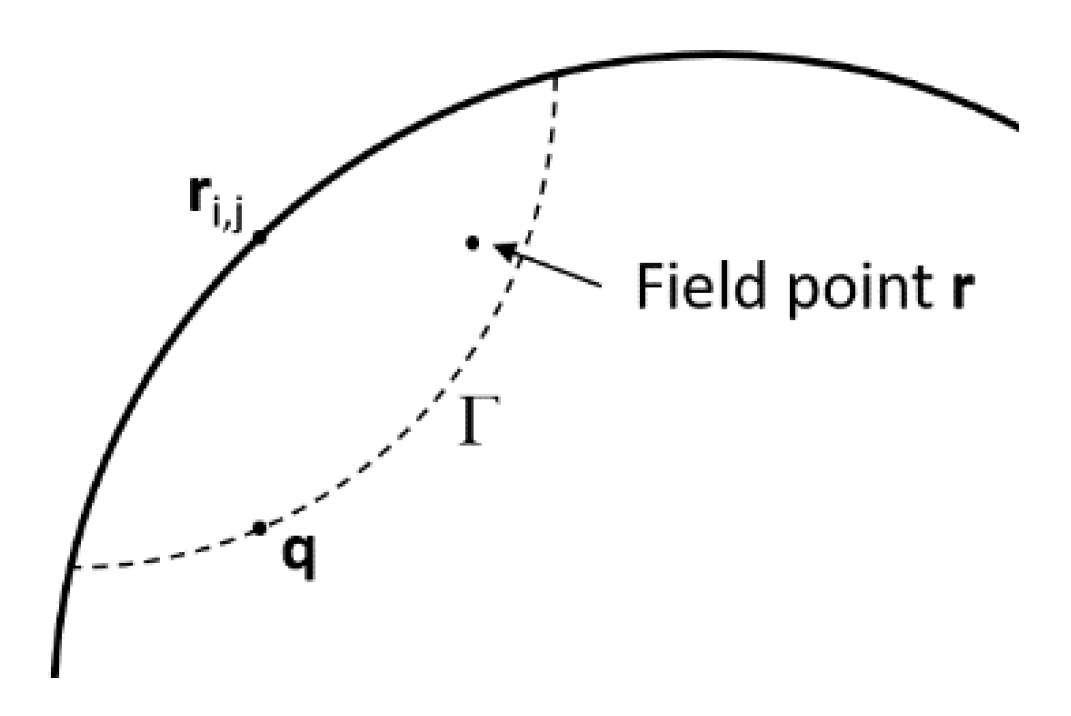
The displacement u(
rij;
r) of a field point r due to a load at the surface grid point
rij can be expressed as
where
q is a point inside the solid body, sufficiently far from the surface (
Figure 2). The term [
u(
rij;
r) and
u(
rij;)], is evaluated using the surface integral approach. The right-hand side one,
u(
rij;
q), is obtained from the FE model.
The term between square brackets represents the deflection of r with respect to point q. This relative component can be better estimated using the Bousinesq half-space solution [
21] rather than using the FE results. The deformation of the body will, in fact, not significantly affect this term. On the other hand, the term
u(
rij;
q) is not significantly affected by local stresses at the surface. This if q is far enough from the surface.
u(
rij;
q) is better estimated from the FE model of the solid body. The location of q is called “matching” point. In order to match the surface integral and FE solutions, a set of points can be used instead of a single point q (
Figure 2) [
22]. Additional details are given in [
23].
While this approach has proven to be significantly more computationally efficient with respect to traditional Finite Element Solvers, further improvements of the models are possible. An even leaner model can be obtained by substituting the bearings with equivalent radial springs with a stiffness obtained from the preliminary steady-state simulations [
24].
3. Model Description
The studied transmission is a single-stage planetary gearbox that has been already studied and tested by the authors in terms of NVH (Noise, Vibrations and Harshness) [
25,
26] and thermal [
27] behavior on an electrical closed-loop test rig made by an electric motor, a generator and two inverters. The meshing between teeth (GMF = 1800 Hz) was the main source of excitation. Vibrations were measured by means of two piezoelectric accelerometers (PCB M352C68) fixed on the housing of the gearbox by means of magnetic supports.
While the present approach could be exploited for any kind of gearbox, it could be particularly suitable for complex/expensive systems, such as wind turbines. For this reason, in the present research a planetary gearbox, which is characterized by the same gear kinematics as most of the wind turbines was used. The aim of performing the analysis on a small commercial gearbox is, on the one hand, related to the possibility of measuring the real responses with the available equipment. On the other hand, it was important for this analysis to generate data for an architecture that is freely available on the market for a reasonable price, and that is accessible to everyone for further studies.
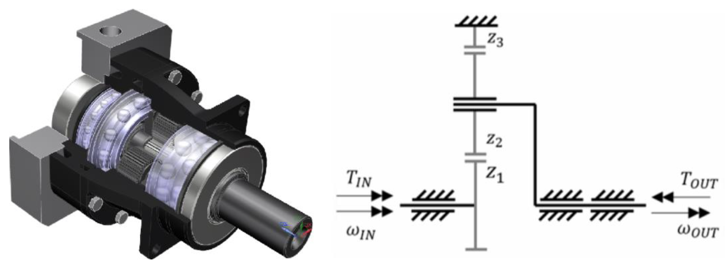
The sun gear (z1) is mounted on the input shaft that is supported by one roller bearing (
Figure 3).
The planet carrier (output shaft) supports three planets (z2), engaging both with the sun gear and the annulus (z3). Two roller bearings support the planet carrier.
Table 1 shows the geometrical and material parameters of the gearbox.
The torque and the rotational speed are those specified by the gearbox manufacturer as “nominal values”. The worst-case scenario (tilting torque) was considered. Therefore, the simulations were performed with an input speed of 3000 rpm an output torque of 120 Nm. The housing is constrained to the ground corresponding to the bolt holes. Details of the FE model will be discussed further in the next sections of this paper.
3.1. FE Model Description
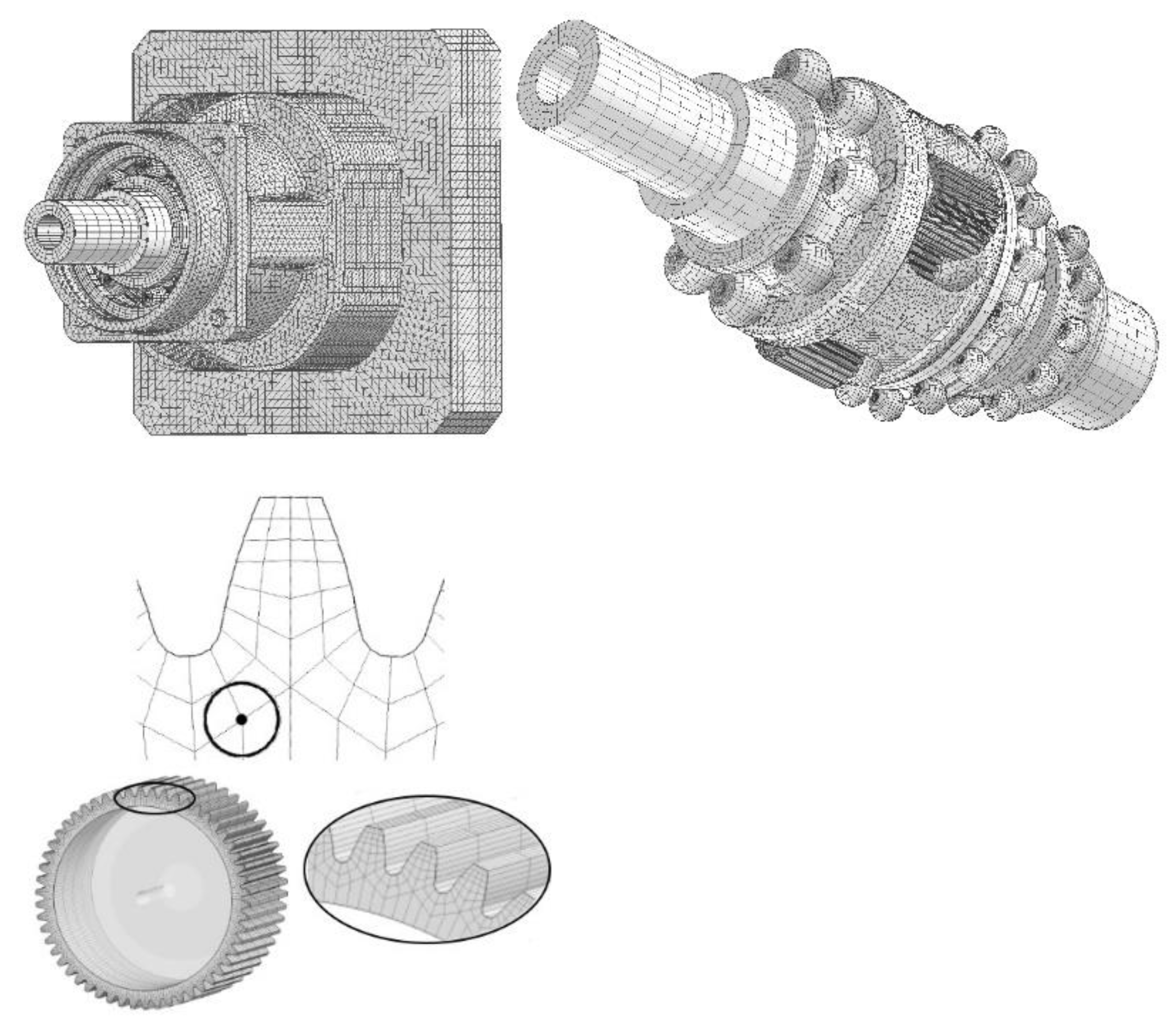
As previously mentioned, a coarse grid was created on each element of the system.
Figure 4 shows the actual mesh used from the FE to estimate the main deflections and stiffnesses of the mechanical components. From this preliminary calculation, the forces exchanged in the contacts are calculated and passed to the contact model, which calculates the contact pressures via semi-analytical functions (i.e., Hertz) in the contact proximity.
Simulations were performed in healthy and damage conditions. From the simulations, it is possible to extract stresses, displacements, velocities, and/or accelerations at any point. While in the past, the accelerations were used to evaluate the NHV behavior [
28], in the present research, the stress field was used to compare the health and the damaged solutions.
3.2. Healthy Conditions Simulation
As a reference point, the simulation of the system in healthy conditions is performed. The obtained results are used as a benchmark.
Figure 4 reports the simulation of the entire model.
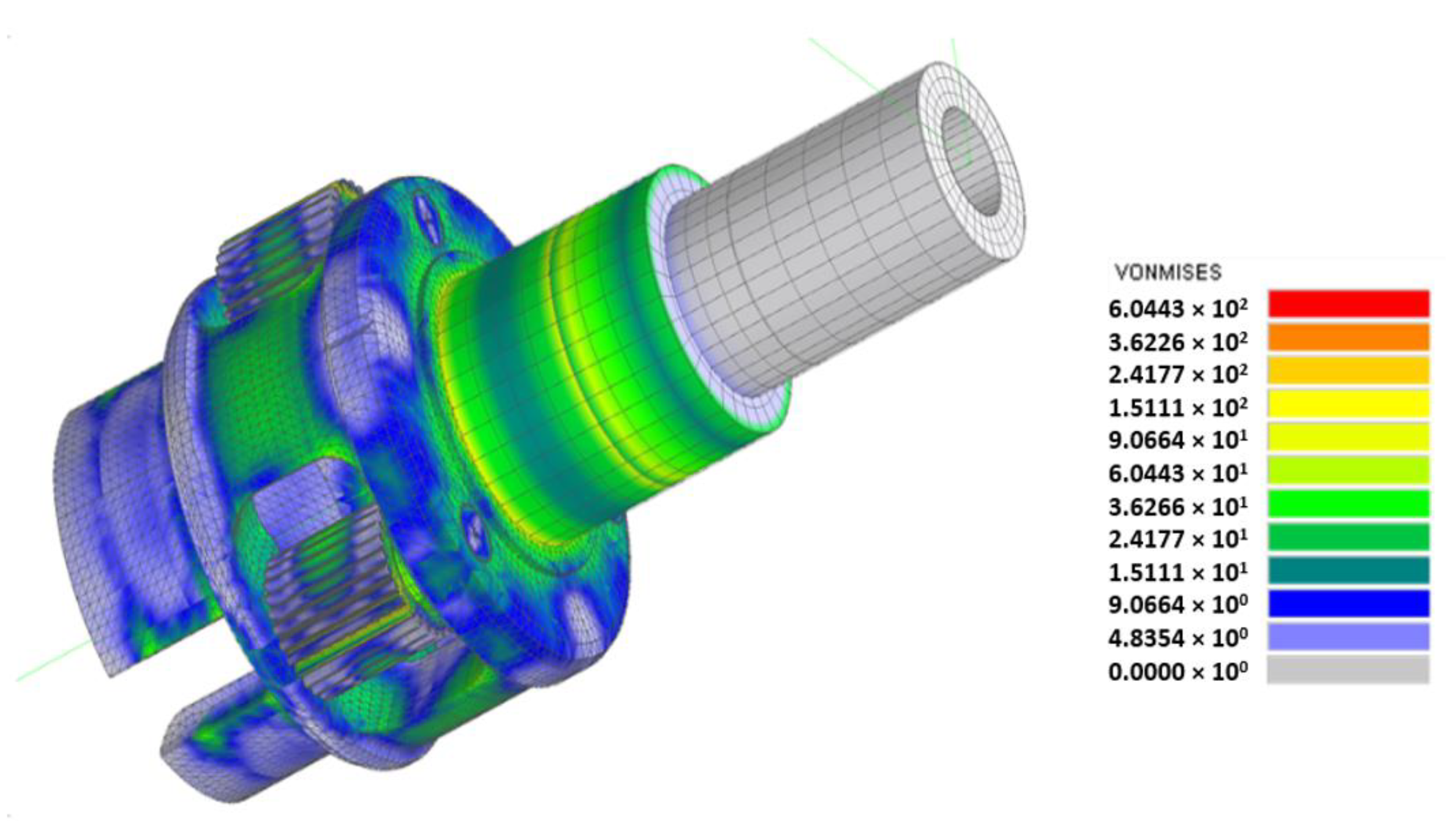
Figure 5 shows the stress state on the planet carrier and the satellites.
3.3. Tooth Surface Pits
The initial type of defect studied is the surface pits due to contact fatigue. Pits are basically small cavities that arise due to the coalescence of sub-superficial cracks, which, in turn, nucleate due to a peak in the sub-superficial shear stress [
29].
Surface defects (pits) are modelled on one of the teeth of the sun gear. To evaluate the sensitivity of the model to this type of defect, a considerable size pit was added to the surface of the tooth. The pit longitudinal size is 10 mm.
To reduce the complexity of the analysis, the simulated pits are modelled in the centre of the face of the tooth (pitch circle). The authors experimentally studied this configuration for iron gears [
30], for case-carburized and nitride steel gears [
31], and in the presence of surface coatings [
28]. In the experience of the authors, the hypothesis of modelling the damage in the centre of the face is acceptable for the goals of this research. Pits from 1 to 10 mm in width are simulated for the purposes of this study. The depth of the pits is kept constant, as well as their height. The depth of each pit is set to 0.42 mm.
The results obtained from the simulations are coherent to the physical meaning of pitting, which is in a surface cavity that prevents contact between the teeth.
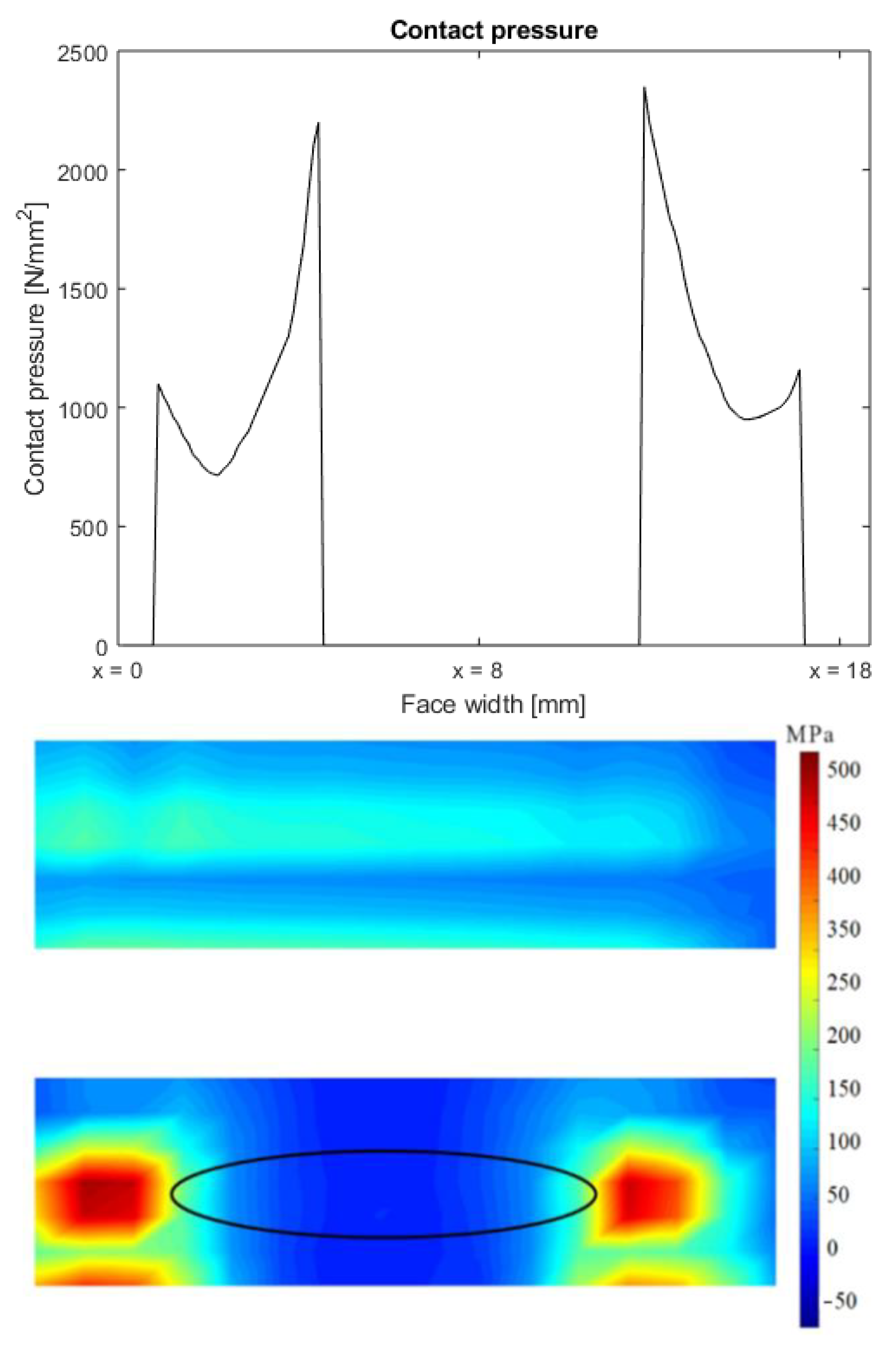
Figure 6 shows how the contact pressure has a discontinuity due to the lack of contact between the two surfaces of the teeth. Therefore, the load is higher on the portion of the surface in contact.
Furthermore, the load is partially transmitted by other teeth pairs, i.e., the load on the teeth next to the damaged teeth is higher than in the nominal conditions. The bottom portion of
Figure 6 shows the stress distribution on the same tooth of the sun gear without (upper contour) and with (lower contour) a 10-mm defect. A sudden reduction of the contact stresses in correspondence of the damage (centre of the teeth—the location and shape of the 10 mm pit is reported by the ellipse plotted on the stress map of the pitted tooth) and some peaks on the lateral sides can be observed. The pattern of the stress is higher on the left side of the face of the tooth, and it decreases while moving on the right. This is due to the stiffness of the sun gear and the carrier. Furthermore,
Figure 6 clearly shows how the pit directly influences the load on the tooth, reducing the contact area and increasing the contact stresses. In the lower part of both stress maps, the stresses show another highly loaded zone corresponding to the tooth root notch.
3.4. Tooth Root Cracks
In addition to the surface damage, the tooth root cracks have also been studied. A 13.5-mm crack was applied to the root of the tooth of the engaged sun gear. This was made by disconnecting the neighbouring mesh elements. The stress is evaluated at the same node used for the extraction of the data with the pitting damage (
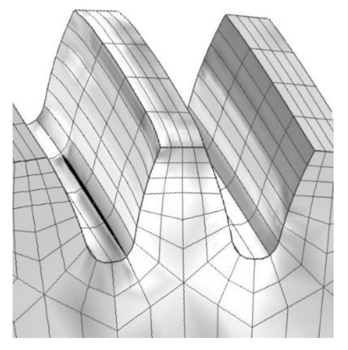
Figure 4). A deformed view of the tooth with the crack is provided in
Figure 7. The black zone at the root of the toot represents the crack applied to the model.
The simulation performed with the crack pointed out how the approach is properly capable of reproducing the effects of the crack and how the stresses near the root of the tooth (
Figure 4) are affected by the presence of this type of defect.
4. Discussion and Results
The aim of this work is the evaluation of the behavior of a gearbox under different damage scenarios to understand if a SHM strategy could be effectively developed for such applications. The FEM analysis allows the evaluation of how different damage affects the stresses in different positions on the gears. This information could be exploited for fine-tuning a SHM strategy.
4.1. Tooth Surface Pits
The stress contours of each simulation were analyzed to evaluate how the presence of surface damage influences the results. These pointed out how an increase in terms of stresses can be observed even in the root of the damaged tooth. Considering the difficulty of placing strain gauges directly on the tooth flank, this finding suggests that the measurement could be performed in the proximity of the root of the tooth (i.e., far from the surface damage), ensuring the presence of the damage can be detected.
The stresses have been evaluated on both sides of the gears. On the one hand, this allows the evaluation of the system deflections (deformations of the carrier and the sun gear rotor). On the other hand, it provides useful information to estimate the position of the damage along the face width.
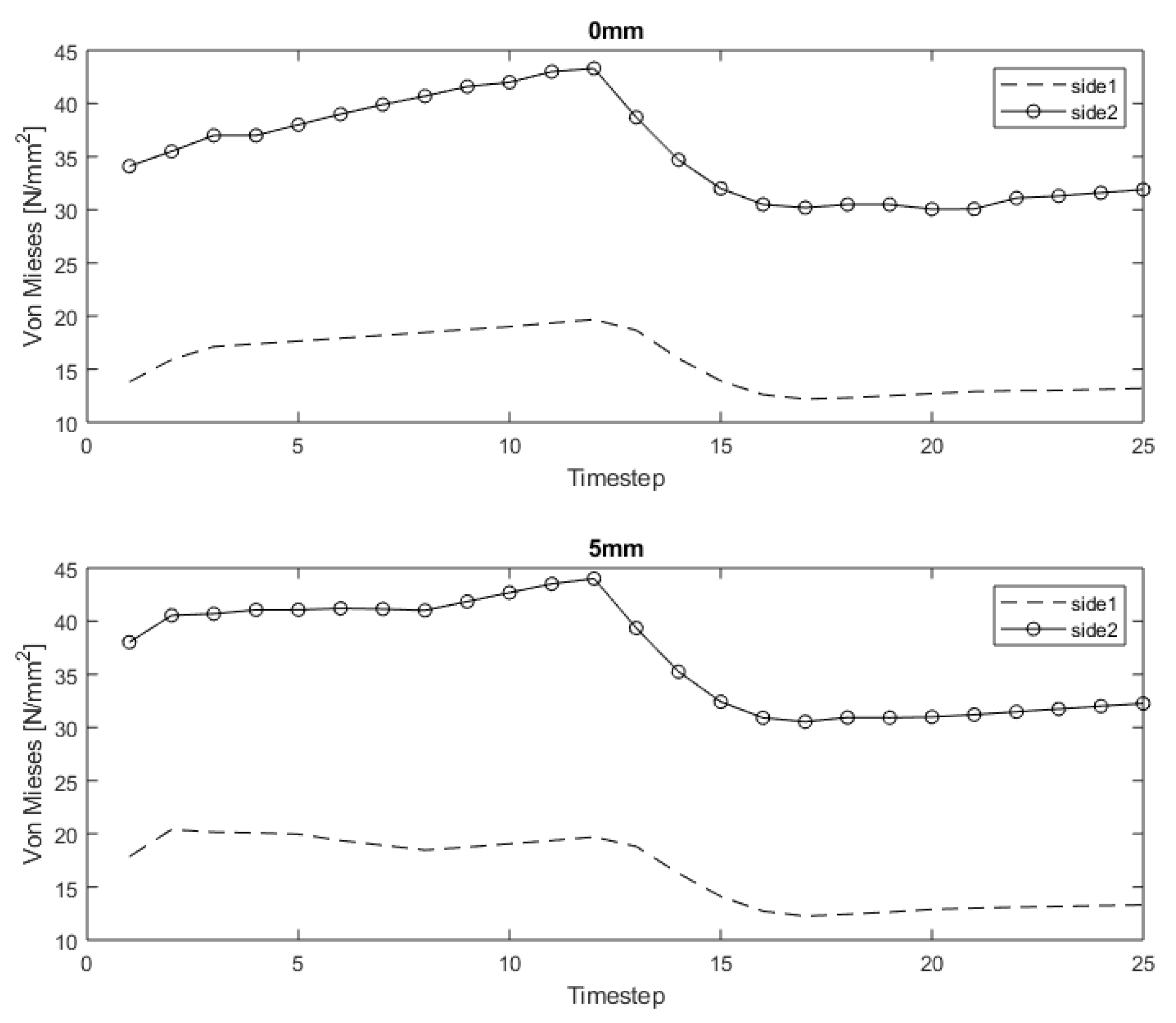
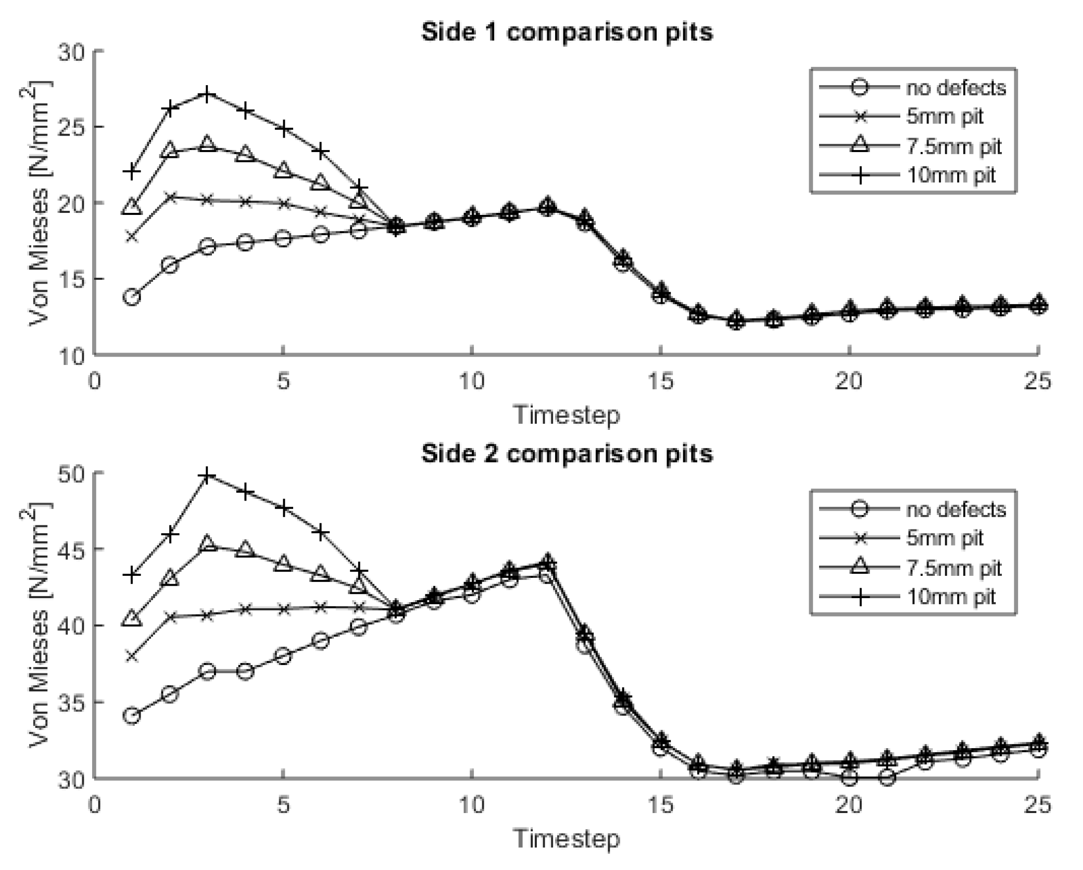
Figure 8 and
Figure 9 show the stresses vs. time for the damage with different dimensions but always centered on the flank. The curves show similar trends but differ in magnitude. This is due to the tooth load contact and the deflection of the shaft during operations. Indeed, stresses are higher on the lateral side of the gear in which the system shows a higher stiffness and, in turn, lower on the opposite side where the planet carrier deformations reduce the contact pressures.
The shape of the curves appears to be almost identical on both sides. This evidence can be explained by the geometry in combination with a centered location of the damage; indeed, being the pit centered in the middle of the face of the tooth and being its geometry elliptical, the fault is symmetrical with respect of the vertical axis of the tooth. Therefore, applying a load on the tooth face leads to similar results on the two lateral points (
Figure 4), which show, in turn, an offset in the stress values.
Moreover, having two points of data extraction (potential measurement points once the SHM will be implemented on a real system) could be useful also in the presence of non-symmetric defects where the initial offset (due to the stiffness of the system) changes with the evolution of non-centered defects.
Twenty-five positions for each engagement were simulated.
Figure 10 shows the root/rim stresses on both sides of the sun gear for different surface damage and different mating positions. The sudden variation at timestep 12 is related to the variation of the number of teeth in contact (from 1 to 2).
The outcomes of this assessment point out the predictability of the pit size in relation to the measured stresses leading the study in the direction of the development of a SHM strategy. The graphs report how the different defects (differing for the dimension) promote different stresses in the tooth root/gear rim. In particular, for the third level of surface damage tested (5–7.5 and 10 mm), the increase in the rim stress, with respect to the healthy conditions, shows a peak (when the pit passes through the contact—position 3), with magnitude results of +25%, +45% and +75%, respectively. This evidence shows the adequacy of a stress-based approach to capture the damage severity.
This evidence can be properly exploited for further SHM developments.
Indeed, with a higher number of simulations based on different cases, a stress-damage relation can be developed, helping to interpret a potential strain-gauge signal.
It should be mentioned that the aim of this work was to evaluate the feasibility of this type of technology for setting up the SHM and specifically to understand the impact of a surface defect on different physical signals. Future work will be the exploitation of these results for the development of a SHM algorithm and its application to a real system.
4.2. Tooth Root Cracks
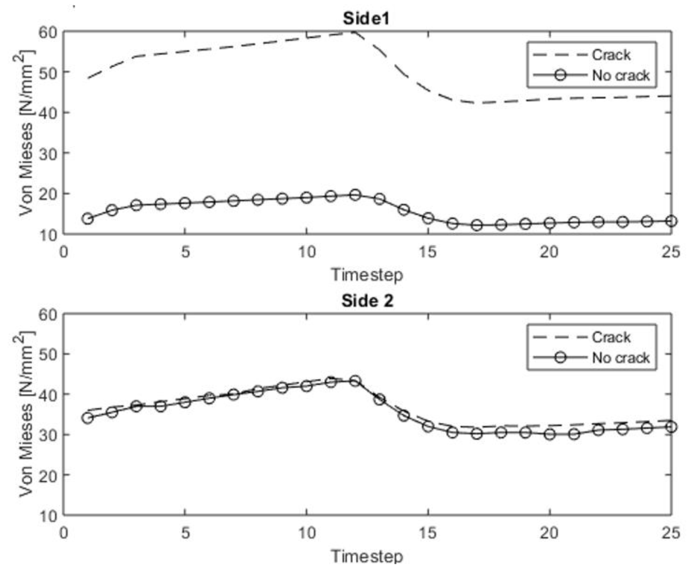
The second analyzed failure is the tooth root bending, i.e., the root cracks. Assuming that the crack is nucleating on side 1 of the sun gear, the stresses on this side result higher than the stresses on side 2 (as reported in
Figure 11). In
Figure 12, the results are compared for different defect sizes. Also, in this case, the numerical results show how stress variations could be captured by a sensor placed near the root of the tooth/gear rim.
Figure 13 reports the stress trends for the different conditions (results referred to side 1 in the upper plot and to side 2 in the lower diagram). The tooth root crack seems to have more influence on the stresses with respect to the pitting phenomenon (having a similar main dimension).
The trend of the stresses in the presence of cracks have a more homogeneous variation compared to the one coming from the pitted conditions that promote variations of the stress levels only for few engagement positions. This is due to the defect typology, which constantly influences the contact position during gear meshing, while the presence of surface damage significantly affects the root stresses only when the pit passes across the contact. Moreover, also the percentage increase of the rim stresses is higher—i.e., for the 13.5 mm crack, +300%. In addition, only the stress on one side of the rim results significantly affected by the presence of this defect. This evidence supports the statement that having two stress acquisition positions on the opposite sides of the rim allows for the prediction of the axial position of the defect.
4.3. Comparison
The analysis of the results shows that the stress trends differ depending on the type of defect, while the variation in magnitude can be related to the entity of the damage. The unbalance in terms of the stress between symmetric points (on opposite sides of the gears) can be an indication of the effective position of the damage.
The relation between the surface damage and the stress variation results is not linear. Moreover, the variations associated with the studied defect sizes are significant and compatible with the accuracy of most of the commercial strain gages.
For the tooth root defects, the variations of the rim stresses in the presence of cracks are even more significant.
These considerations might be useful to distinguish between different defects when developing a SHM model. For this specific configuration, for example, it seems that a layout that foresees sensors all around the sun gear rim on both sides of the gear could potentially capture the presence of any defect, its type, its magnitude and, its (axial) position. In general, considering the system architecture under study, this approach could be easily extended and applied to real wind turbine gearboxes.
5. Conclusions
Several FE simulations have been performed for a healthy and a damaged single-stage planetary gearbox. This peculiar gear kinematics was selected considering that wind turbines (in which planetary solutions are widely used), are one of the geared systems that could significantly benefit from a model-based SHM.
A hybrid numerical–analytical approach was chosen to study the impact of the defects on the stresses for assessing the applicability of a strain-gauge-based condition monitoring strategy to predict the type, size, and position of the damage.
The approach relies on two steps. First, the numerical FE model is solved for a coarse grid to evaluate the forces in the contacts considering the macro-deflections of the bodies. Second, the contacts are solved by means of analytical equations (based on the Hertzian theory) and the contact pressures estimated. In this manner, it is possible to simulate a real system with mechanical components without geometrical simplifications, ensuring at the same time a reasonable computational effort.
Two typologies of damage that have been considered are tooth root cracks and surface damage (pitting).
The characteristics of the damage were related to their impact on the system behavior by evaluating the stresses on the gear rim, just below the tooth root.
For the studied gearbox, strain gauges mounted on the lateral sides of each gear rim seem to be a feasible solution for detecting the presence/severity, type and the position of the defects.
While the presence of pitting promotes an instantaneous increase of the stresses in the rim, the presence of tooth root bending cracks causes an averaged increase of the stress level. This evidence proves the adequacy of a stress-based approach for the detection of several types of damage. Moreover, the simulations have shown that surface damage of about 10 mm produces an increase in the stress on the rim of about 75%. For a 5 mm pit, the stress increase is about 25%. This finding confirms the capability of the model to predict the severity of the damage.
Finally, the presence of a 13.5-mm crack on one side of the tooth (axially) produces an increment of the stress on one side of the rim of about 300%, while on the opposite side, the stress only increases by 5%. This effect confirms the capability of predicting the damage type, severity, and position in the axial direction with two strain sensors for each tooth.
The presence of root cracks can be captured by looking at the average variation of the root stress while the pits produce local stress peaks, then the defects pass through the contact. In both cases, the stress variation with respect to the healthy condition is directly related to the severity of the damage. Moreover, a comparison between the measures on opposite sides of the gear can indicate the position of the damage.


