The Use of a Vibro-Acoustic Based Method to Determine the Composite Material Properties of a Replicate Clavicle Bone Model

 ,
,
Abstract
:1. Introduction
2. Materials and Methods
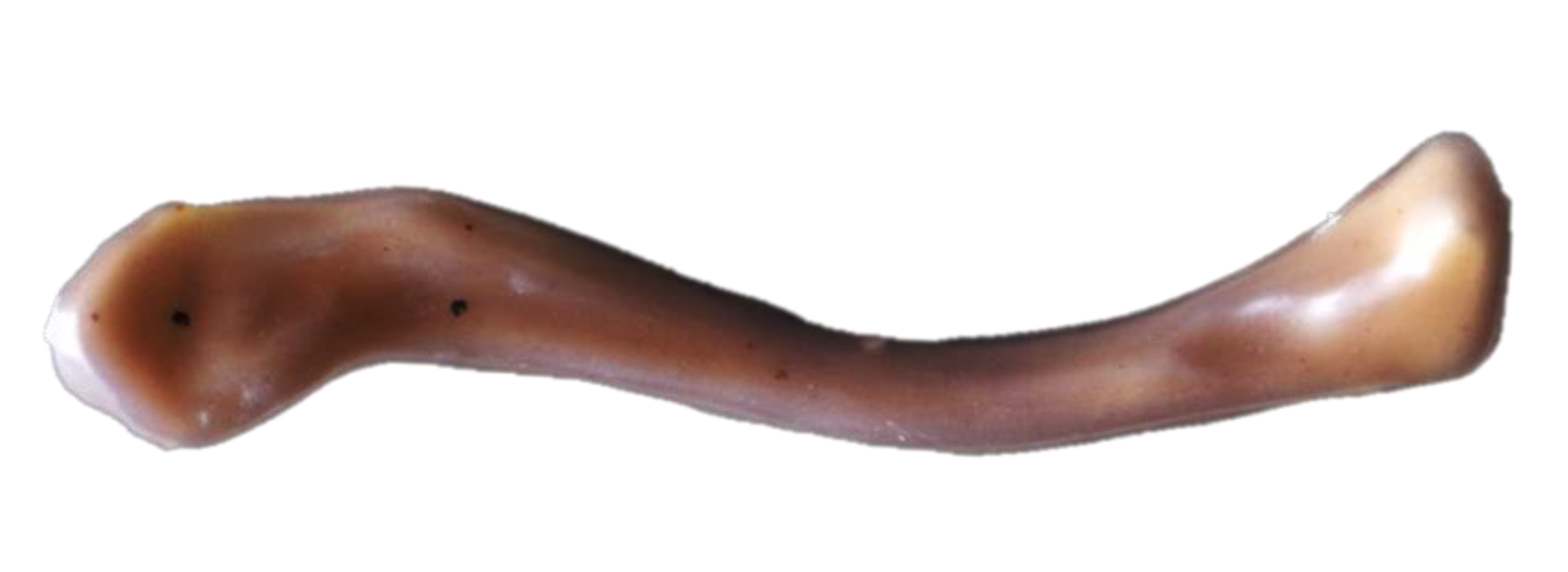
2.1. Composite Bone Model
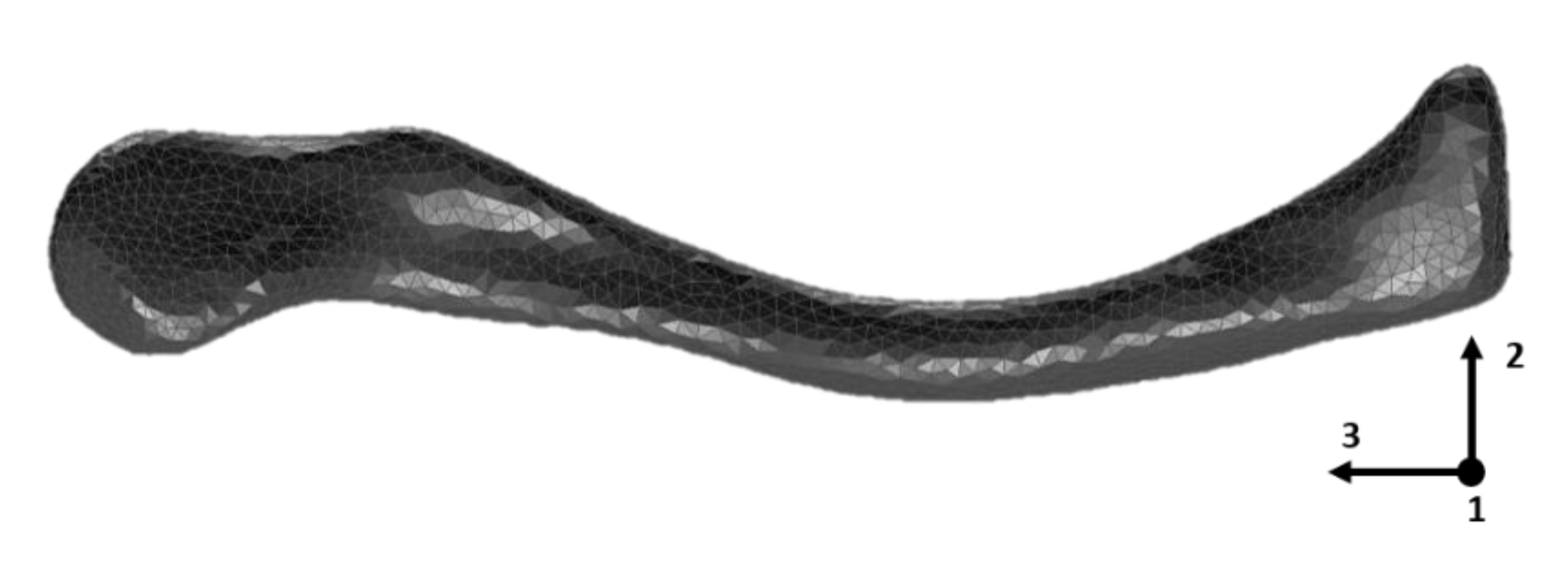
2.2. Finite Element Model
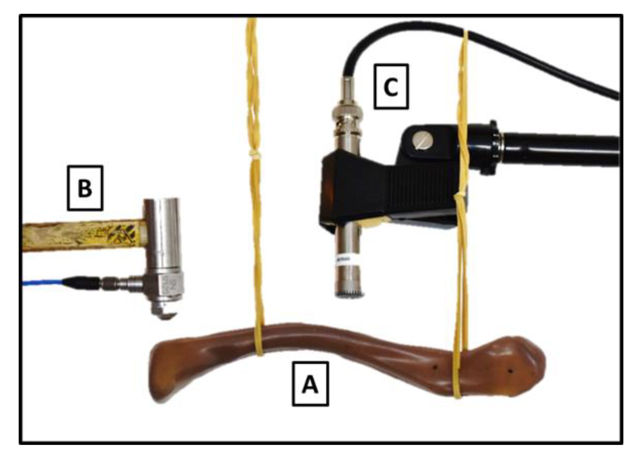
2.3. Experimental Acoustic Modal Analysis
2.4. FE Parameter Updating Protocol
3. Results
4. Discussion
5. Conclusions
Author Contributions
Funding
Acknowledgments
Conflicts of Interest
References
- Eden, L.; Doht, S.; Frey, S.P.; Ziegler, D.; Stoyhe, J.; Fehske, K.; Blunk, T.; Meffert, R.H. Biomechanical comparison of the Locking Compression superior anterior clavicle plate with seven and ten hole reconstruction plates in midshaft clavicle fracture stabilisation. Int. Orthop. 2012, 36, 2537–2543. [Google Scholar] [CrossRef] [PubMed] [Green Version]
- Pujari-Palmer, M.; Robo, C.; Persson, C.; Procter, P.; Engqvist, H. Influence of cement compressive strength and porosity on augmentation performance in a model of orthopedic screw pull-out. J. Mech. Behav. Biomed. Mater. 2018, 77, 624–633. [Google Scholar] [CrossRef] [PubMed]
- Robertson, C.; Celestre, P.; Mahar, A.; Schwartz, A. Reconstruction plates for stabilization of mid-shaft clavicle fractures: Differences between nonlocked and locked plates in two different positions. J. Shoulder Elb. Surg. 2009, 18, 204–209. [Google Scholar] [CrossRef] [PubMed]
- Sakai, R.; Matsuura, T.; Tanaka, K.; Uchida, K.; Nakao, M.; Mabuchi, K. Comparison of Internal Fixations for Distal Clavicular Fractures Based on Loading Tests and Finite Element Analyses. Sci. World J. 2014, 2014, 1–6. [Google Scholar] [CrossRef] [PubMed]
- Uzer, G.; Yildiz, F.; Batar, S.; Bozdag, E.; Kuduz, H.; Bilsel, K. Biomechanical comparison of three different plate configurations for comminuted clavicle midshaft fracture fixation. J. Shoulder Elb. Surg. 2017, 26, 2200–2205. [Google Scholar] [CrossRef] [PubMed]
- Vancleef, S.; Vanhove, H.; Herteleer, M.; Stefaan, N.; Joost, D.; Jos, V.S. Case-study: Assessment of a patient-specific and commercial plate for clavicle fracture fixation. In Proceedings of the Congress of the European Society of Biomechanics, Sevilla, Spain, 2–5 July 2017. [Google Scholar]
- Leuridan, S.; Goossens, Q.; Pastrav, L.; Roosen, J.; Mulier, M.; Denis, K.; Desmet, W.; Sloten, J.V. Determination of replicate composite bone material properties using modal analysis. J. Mech. Behav. Biomed. Mater. 2017, 66, 12–18. [Google Scholar] [CrossRef]
- Cristofolini, L.; Viceconti, M. Mechanical validation of whole bone composite tibia models. J. Biomech. 2000, 33, 279–288. [Google Scholar] [CrossRef]
- Grover, P.; Albert, C.; Wang, M.; Harris, G.F. Mechanical characterization of fourth generation composite humerus. Proc. Inst. Mech. Eng. Part H J. Eng. Med. 2011, 225, 1169–1176. [Google Scholar] [CrossRef]
- Cronskär, M. Strength analysis of clavicle fracture fixation devices and fixation techniques using finite element analysis with musculoskeletal force input. Med. Biol. Eng. Comput. 2015, 53, 759–769. [Google Scholar] [CrossRef]
- Favre, P.; Kloen, P.; Helfet, D.L.; Werner, C.M.L. Superior versus Anteroinferior Plating of the Clavicle: A Finite Element Study. J. Orthop. Trauma 2011, 25, 661–665. [Google Scholar] [CrossRef]
- Huang, T.-L.; Chen, W.-C.; Lin, K.-J.; Tsai, C.-L.; Lin, K.-P.; Wei, H.-W. Conceptual finite element study for comparison among superior, anterior, and spiral clavicle plate fixations for midshaft clavicle fracture. Med. Eng. Phys. 2016, 38, 1070–1075. [Google Scholar] [CrossRef] [PubMed]
- Ni, M.; Niu, W.; Wong, D.W.-C.; Zeng, W.; Mei, J.; Zhang, M. Finite element analysis of locking plate and two types of intramedullary nails for treating mid-shaft clavicle fractures. Injury 2016, 47, 1618–1623. [Google Scholar] [CrossRef] [PubMed]
- Pendergast, M.; Rusovici, R. A finite element parametric study of clavicle fixation plates. Int. J. Numer. Methods Biomed. Eng. 2015, 31, e02710. [Google Scholar] [CrossRef] [PubMed]
- Rusovici, R.; Pendergast, M.; O’Brien, J.T.; Ghita, I. Finite Element Modeling of Human Clavicle under Dynamic Loading. Biomed. Eng. 2013, 10, 531–537. [Google Scholar] [CrossRef] [Green Version]
- Zeng, L.; Wei, H.; Liu, Y.; Zhang, W.; Pan, Y.; Zhang, W.; Zhang, C.; Zeng, B.; Chen, Y. Titanium Elastic Nail (TEN) versus Reconstruction Plate Repair of Midshaft Clavicular Fractures: A Finite Element Study. PLoS ONE 2015, 10, e0126131. [Google Scholar] [CrossRef]
- Viceconti, M.; Olsen, S.; Nolte, L.-P.; Burton, K. Extracting clinically relevant data from finite element simulations. Clin. Biomech. 2005, 20, 451–454. [Google Scholar] [CrossRef]
- Tiossi, R.; Vasco, M.A.A.; Lin, L.; Conrad, H.J.; Bezzon, O.L.; Ribeiro, R.F.; Fok, A.S.L. Validation of finite element models for strain analysis of implant-supported prostheses using digital image correlation. Dent. Mater. 2013, 29, 788–796. [Google Scholar] [CrossRef]
- Ghosh, R.; Gupta, S.; Dickinson, A.; Browne, M. Experimental Validation of Finite Element Models of Intact and Implanted Composite Hemipelvises Using Digital Image Correlation. J. Biomech. Eng. 2012, 134, 081003. [Google Scholar] [CrossRef]
- Dickinson, A.S.; Taylor, A.C.; Ozturk, H.; Browne, M. Experimental Validation of a Finite Element Model of the Proximal Femur Using Digital Image Correlation and a Composite Bone Model. J. Biomech. Eng. 2011, 133, 014504. [Google Scholar] [CrossRef]
- Grassi, L.; Väänänen, S.P.; Amin Yavari, S.; Weinans, H.; Jurvelin, J.S.; Zadpoor, A.A.; Isaksson, H. Experimental validation of finite element model for proximal composite femur using optical measurements. J. Mech. Behav. Biomed. Mater. 2013, 21, 86–94. [Google Scholar] [CrossRef]
- Gray, H.A.; Taddei, F.; Zavatsky, A.B.; Cristofolini, L.; Gill, H.S. Experimental Validation of a Finite Element Model of a Human Cadaveric Tibia. J. Biomech. Eng. 2008, 130, 031016. [Google Scholar] [CrossRef] [PubMed]
- Li, Z.; Kindig, M.W.; Kerrigan, J.R.; Kent, R.W.; Crandall, J.R. Development and validation of a subject-specific finite element model of a human clavicle. Comput. Methods Biomech. Biomed. Eng. 2013, 16, 819–829. [Google Scholar] [CrossRef] [PubMed]
- Mottershead, J.E.; Link, M.; Friswell, M.I. The sensitivity method in finite element model updating: A tutorial. Mech. Syst. Signal Process. 2011, 25, 2275–2296. [Google Scholar] [CrossRef]
- Taylor, W.R.; Roland, E.; Ploeg, H.; Hertig, D.; Klabunde, R.; Warner, M.D.; Hobatho, M.C.; Rakotomanana, L.; Clift, S.E. Determination of orthotropic bone elastic constants using FEA and modal analysis. J. Biomech. 2002, 35, 767–773. [Google Scholar] [CrossRef]
- Heylen, W.; Sas, P. Modal Analysis Theory and Testing; Departement Werktuigkunde, Katholieke Universiteit Leuven: Leuven, Belgium, 2006; ISBN 90-73802-61-X. [Google Scholar]
- Bernard, S.; Grimal, Q.; Laugier, P. Accurate measurement of cortical bone elasticity tensor with resonant ultrasound spectroscopy. J. Mech. Behav. Biomed. Mater. 2013, 18, 12–19. [Google Scholar] [CrossRef] [PubMed]
- Semaan, M.; Mora, P.; Bernard, S.; Launay, F.; Payan, C.; Lasaygues, P.; Pithioux, M.; Baron, C. Assessment of elastic coefficients of child cortical bone using resonant ultrasound spectroscopy. J. Mech. Behav. Biomed. Mater. 2019, 90, 40–44. [Google Scholar] [CrossRef] [Green Version]
- Couteau, B.; Hobatho, M.-C.; Darmana, R.; Brignola, J.-C.; Arlaud, J.-Y. Finite element modelling of the vibrational behaviour of the human femur using CT-based individualized geometrical and material properties. J. Biomech. 1998, 31, 383–386. [Google Scholar] [CrossRef]
- Hobatho, M.C.; Darmana, R.; Pastor, P.; Barrau, J.J.; Laroze, S.; Morucci, J.P. Development of a three-dimensional finite element model of a human tibia using experimental modal analysis. J. Biomech. 1991, 24, 371–383. [Google Scholar] [CrossRef]
- Neugebauer, R.; Werner, M.; Voigt, C.; Steinke, H.; Scholz, R.; Scherer, S.; Quickert, M. Experimental modal analysis on fresh-frozen human hemipelvic bones employing a 3D laser vibrometer for the purpose of modal parameter identification. J. Biomech. 2011, 44, 1610–1613. [Google Scholar] [CrossRef]
- Scholz, R.; Hoffmann, F.; von Sachsen, S.; Drossel, W.-G.; Klöhn, C.; Voigt, C. Validation of density–elasticity relationships for finite element modeling of human pelvic bone by modal analysis. J. Biomech. 2013, 46, 2667–2673. [Google Scholar] [CrossRef]
- Sawbones Biomechanical Catalog. Available online: http://www.sawbones.com/UserFiles/Docs/biomechanical_catalog.pdf (accessed on 23 September 2020).
- Leuridan, S.; Goossens, Q.; Vander Sloten, T.; De Landsheer, K.; Delport, H.; Pastrav, L.; Denis, K.; Desmet, W.; Vander Sloten, J. Vibration-based fixation assessment of tibial knee implants: A combined in vitro and in silico feasibility study. Med. Eng. Phys. 2017, 49, 109–120. [Google Scholar] [CrossRef] [PubMed]
- Bessho, M.; Ohnishi, I.; Matsuyama, J.; Matsumoto, T.; Imai, K.; Nakamura, K. Prediction of strength and strain of the proximal femur by a CT-based finite element method. J. Biomech. 2007, 40, 1745–1753. [Google Scholar] [CrossRef] [PubMed]
- Petersen, Ø.W.; Øiseth, O. Sensitivity-based finite element model updating of a pontoon bridge. Eng. Struct. 2017, 150, 573–584. [Google Scholar] [CrossRef] [Green Version]
- Swider, P.; Guérin, G.; Baas, J.; Søballe, K.; Bechtold, J.E. Characterization of bone-implant fixation using modal analysis: Application to a press-fit implant model. J. Biomech. 2009, 42, 1643–1649. [Google Scholar] [CrossRef] [PubMed] [Green Version]
- Alizad, A.; Walch, M.; Greenleaf, J.F.; Fatemi, M. Vibrational Characteristics of Bone Fracture and Fracture Repair: Application to Excised Rat Femur. J. Biomech. Eng. 2006, 128, 300. [Google Scholar] [CrossRef]
- Lowet, G.; Dayuan, X.; Van der Perre, G. Study of the vibrational behaviour of a healing tibia using finite element modelling. J. Biomech. 1996, 29, 1003–1010. [Google Scholar] [CrossRef]
- Hammer, N.; Voigt, C.; Werner, M.; Hoffmann, F.; Bente, K.; Kunze, H.; Scholz, R.; Steinke, H. Ethanol and formaldehyde fixation irreversibly alter bones’ organic matrix. J. Mech. Behav. Biomed. Mater. 2014, 29, 252–258. [Google Scholar] [CrossRef]
- Campoli, G.; Baka, N.; Kaptein, B.L.; Valstar, E.R.; Zachow, S.; Weinans, H.; Zadpoor, A.A. Relationship between the shape and density distribution of the femur and its natural frequencies of vibration. J. Biomech. 2014, 47, 3334–3343. [Google Scholar] [CrossRef]
- Goossens, Q.; Leuridan, S.; Henyš, P.; Roosen, J.; Pastrav, L.; Mulier, M.; Desmet, W.; Denis, K.; Vander Sloten, J. Development of an acoustic measurement protocol to monitor acetabular implant fixation in cementless total hip Arthroplasty: A preliminary study. Med. Eng. Phys. 2017, 49, 28–38. [Google Scholar] [CrossRef]
- Pastrav, L.C.; Devos, J.; Van der Perre, G.; Jaecques, S.V.N. A finite element analysis of the vibrational behaviour of the intra-operatively manufactured prosthesis–femur system. Med. Eng. Phys. 2009, 31, 489–494. [Google Scholar] [CrossRef]
- Henyš, P.; Capek, L.; Fencl, J.; Prochazka, E. Evaluation of acetabular cup initial fixation by using resonance frequency principle. Proc. Inst. Mech. Eng. Part H J. Eng. Med. 2015, 229, 3–8. [Google Scholar] [CrossRef] [PubMed]
- Vayron, R.; Nguyen, V.-H.; Bosc, R.; Naili, S.; Haiat, G. Assessment of the biomechanical stability of a dental implant with quantitative ultrasound: A three-dimensional finite element study. J. Acoust. Soc. Am. 2016, 139, 773–780. [Google Scholar] [CrossRef] [PubMed]
- Cronskär, M.; Rasmussen, J.; Tinnsten, M. Combined finite element and multibody musculoskeletal investigation of a fractured clavicle with reconstruction plate. Comput. Methods Biomech. Biomed. Eng. 2015, 18, 740–748. [Google Scholar] [CrossRef]
- Duprey, S.; Bruyere, K.; Verriest, J.-P. Influence of geometrical personalization on the simulation of clavicle fractures. J. Biomech. 2008, 41, 200–207. [Google Scholar] [CrossRef]
- Gray, H.A.; Zavatsky, A.B.; Taddei, F.; Cristofolini, L.; Gill, H.S. Experimental validation of a finite element model of a composite tibia. Proc. Inst. Mech. Eng. Part H J. Eng. Med. 2007, 221, 315–324. [Google Scholar] [CrossRef] [PubMed]
- Baca, V.; Horak, Z.; Mikulenka, P.; Dzupa, V. Comparison of an inhomogeneous orthotropic and isotropic material models used for FE analyses. Med. Eng. Phys. 2008, 30, 924–930. [Google Scholar] [CrossRef]
- Hellmich, C.; Kober, C.; Erdmann, B. Micromechanics-Based Conversion of CT Data into Anisotropic Elasticity Tensors, Applied to FE Simulations of a Mandible. Ann. Biomed. Eng. 2008, 36, 108–122. [Google Scholar] [CrossRef]
- Gilroy, D.; Young, A.M.; Phillips, A.; Wheel, M.; Riches, P.E. Characterization and Validation of Sawbones Artificial Composite Femur material. In Proceedings of the 7th World Congress of Biomechanics, Boston, MA, USA, 6–11 July 2014; p. 1. [Google Scholar]
- Appendix A: Mechanical Properties. In Mechanics of Optimal Structural Design; John Wiley & Sons, Ltd.: Chichester, UK, 2009; pp. 521–524. ISBN 978-0-470-74978-4.
- Dunlap, J.T.; Chong, A.C.M.; Lucas, G.L.; Cooke, F.W. Structural Properties of a Novel Design of Composite Analogue Humeri Models. Ann. Biomed. Eng. 2008, 36, 1922–1926. [Google Scholar] [CrossRef]
- Heiner, A.D. Structural properties of fourth-generation composite femurs and tibias. J. Biomech. 2008, 41, 3282–3284. [Google Scholar] [CrossRef]


| Cancellous | E [MPa] | ν | ρ [g/cc] | |||
|---|---|---|---|---|---|---|
| Isotropic | 155 | 0.30 | 0.27 | |||
| Cortical | E11 = E22 [GPa] | E33 [GPa] | G13 = G23 [GPa] | ν12 | ν23 | ρ [g/cc] |
| Transversely isotropic | 10 | 16 | 3.3 | 0.26 | 0.26 | 1.64 |
| Sensitivities (%/%) | Cancellous | Cortical | |||||
|---|---|---|---|---|---|---|---|
| Mode Number | ν | E | ν12 | ν23 | E11 = E22 | E33 | G13 = G23 |
| 1 | 0.00 | 0.01 | 0.02 | −0.01 | 0.01 | 0.36 | 0.10 |
| 2 | 0.00 | 0.01 | 0.01 | −0.01 | 0.01 | 0.34 | 0.12 |
| 3 | 0.00 | 0.01 | 0.00 | 0.01 | 0.03 | 0.05 | 0.38 |
| 4 | 0.00 | 0.01 | 0.01 | 0.00 | 0.01 | 0.28 | 0.17 |
| 5 | 0.00 | 0.02 | 0.01 | −0.01 | 0.02 | 0.28 | 0.16 |
| Mode Number | 1 | 2 | 3 | 4 | 5 |
|---|---|---|---|---|---|
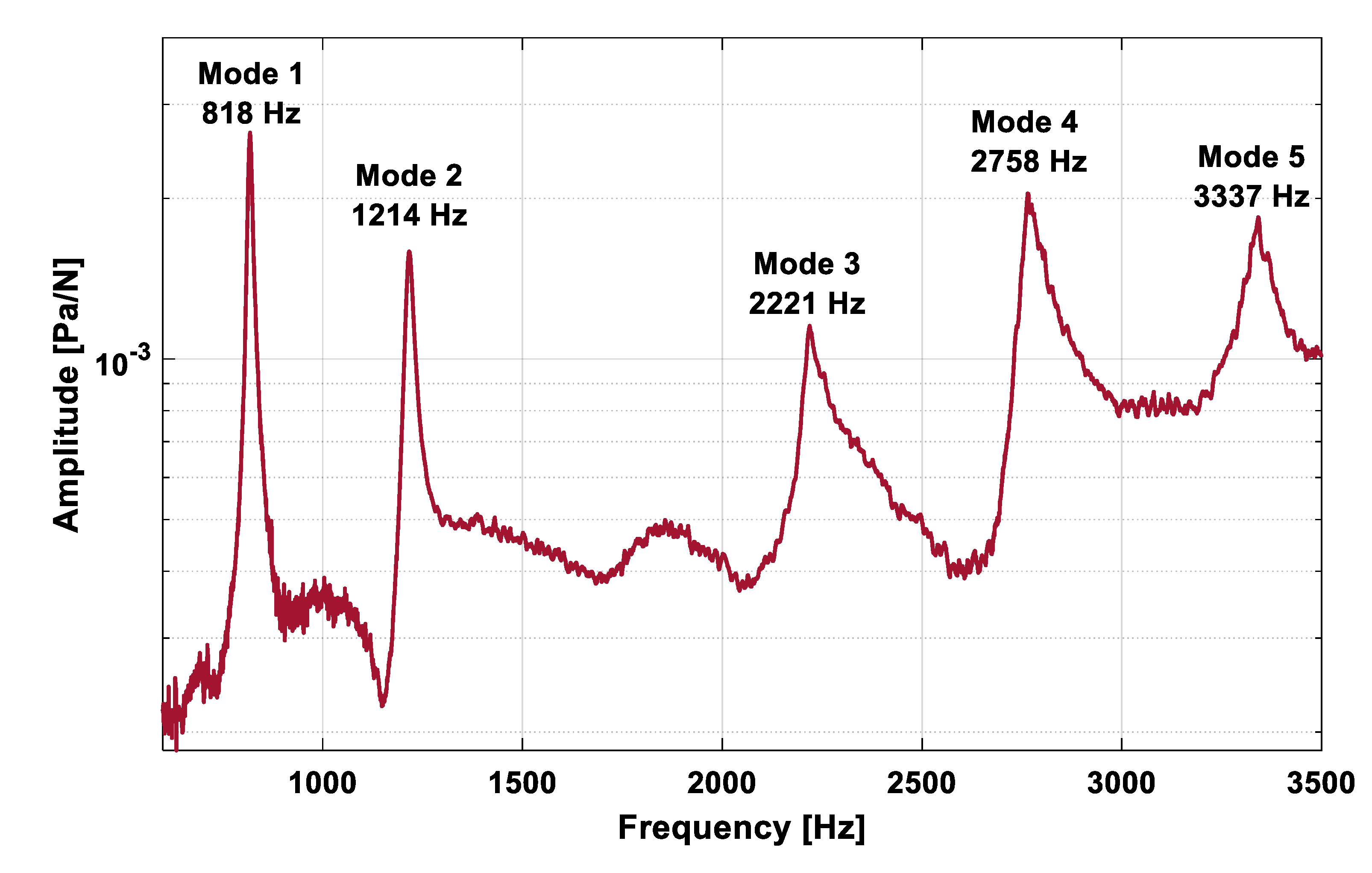
| Experimental natural frequency [Hz] | 818 | 1214 | 2221 | 2758 | 3337 |
| Numerical (FE) frequency before updating [Hz] | 872 | 1284 | 2008 | 2801 | 3372 |
| Difference before updating [%] | 6.6 | 5.7 | −9.6 | 1.5 | 1.1 |
| Numerical (FE) frequency after updating [Hz] | 821 | 1217 | 2221 | 2761 | 3279 |
| Difference after updating [%] | 0.4 | 0.3 | 0.0 | 0.1 | −1.7 |
| Before Updating | After Updating | |
|---|---|---|
| ρcort [g/cc] | 1.640 | 1.658 |
| E33 [GPa] | 16.00 | 12.88 |
| G13 = G23 [MPa] | 3.30 | 4.53 |
© 2020 by the authors. Licensee MDPI, Basel, Switzerland. This article is an open access article distributed under the terms and conditions of the Creative Commons Attribution (CC BY) license (http://creativecommons.org/licenses/by/4.0/).
Share and Cite
Goossens, Q.; Vancleef, S.; Leuridan, S.; Pastrav, L.C.; Mulier, M.; Desmet, W.; Vander Sloten, J.; Denis, K. The Use of a Vibro-Acoustic Based Method to Determine the Composite Material Properties of a Replicate Clavicle Bone Model. J. Funct. Biomater. 2020, 11, 69. https://0-doi-org.brum.beds.ac.uk/10.3390/jfb11040069
Goossens Q, Vancleef S, Leuridan S, Pastrav LC, Mulier M, Desmet W, Vander Sloten J, Denis K. The Use of a Vibro-Acoustic Based Method to Determine the Composite Material Properties of a Replicate Clavicle Bone Model. Journal of Functional Biomaterials. 2020; 11(4):69. https://0-doi-org.brum.beds.ac.uk/10.3390/jfb11040069
Chicago/Turabian StyleGoossens, Quentin, Sanne Vancleef, Steven Leuridan, Leonard Cezar Pastrav, Michiel Mulier, Wim Desmet, Jos Vander Sloten, and Kathleen Denis. 2020. "The Use of a Vibro-Acoustic Based Method to Determine the Composite Material Properties of a Replicate Clavicle Bone Model" Journal of Functional Biomaterials 11, no. 4: 69. https://0-doi-org.brum.beds.ac.uk/10.3390/jfb11040069