Hierarchical Surface Texturing of Hydroxyapatite Ceramics: Influence on the Adhesive Bonding Strength of Polymeric Polycaprolactone


Abstract
:1. Introduction
2. Materials and Methods
2.1. Fabrication of Surface-Textured HAp Ceramics by Micro-Transfer Molding
2.2. Surface Treatments of the Sintered (Textured) HAp Ceramics
2.3. Characterization
2.4. Statistical Analysis
3. Results and Discussion
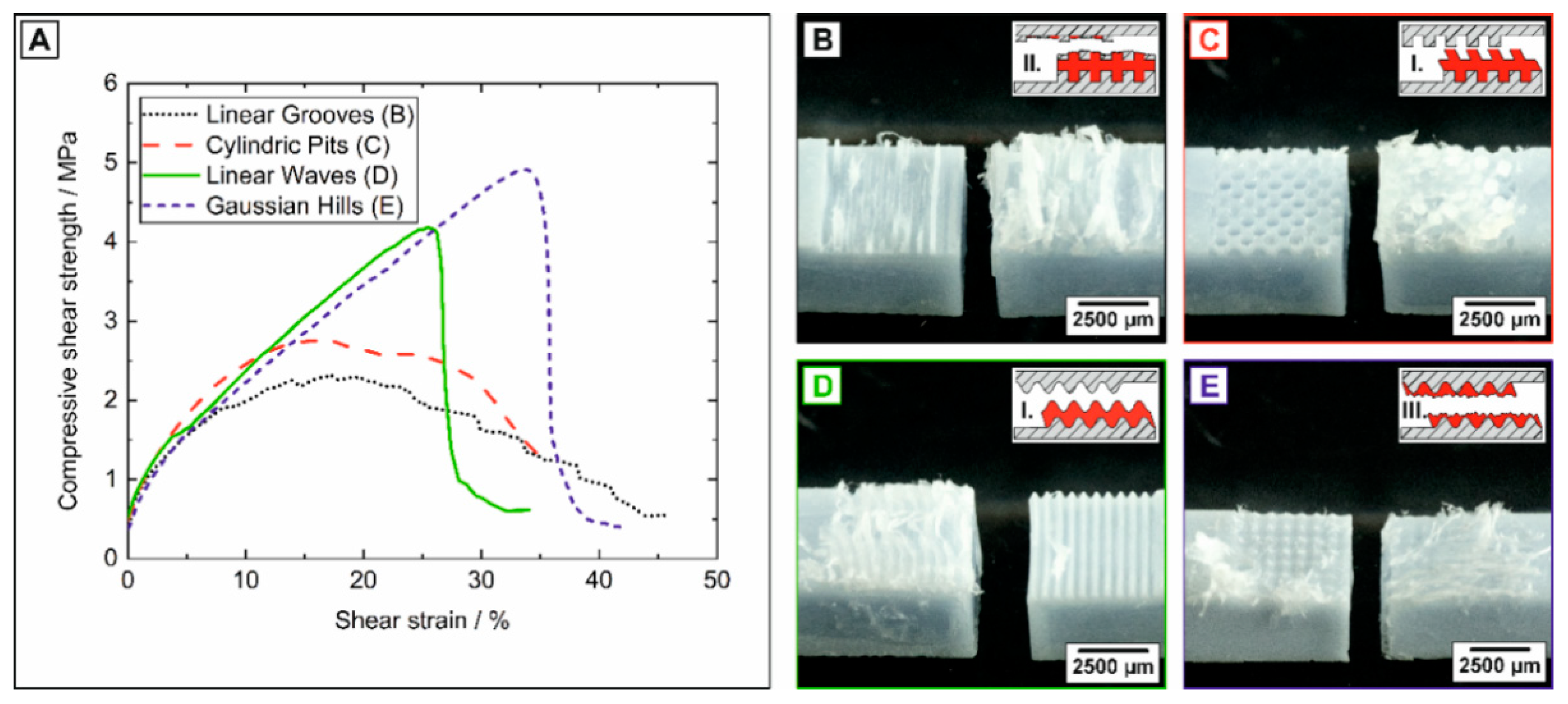
3.1. Microstructural Characterization of Macro-Surface-Textured HAp Ceramics
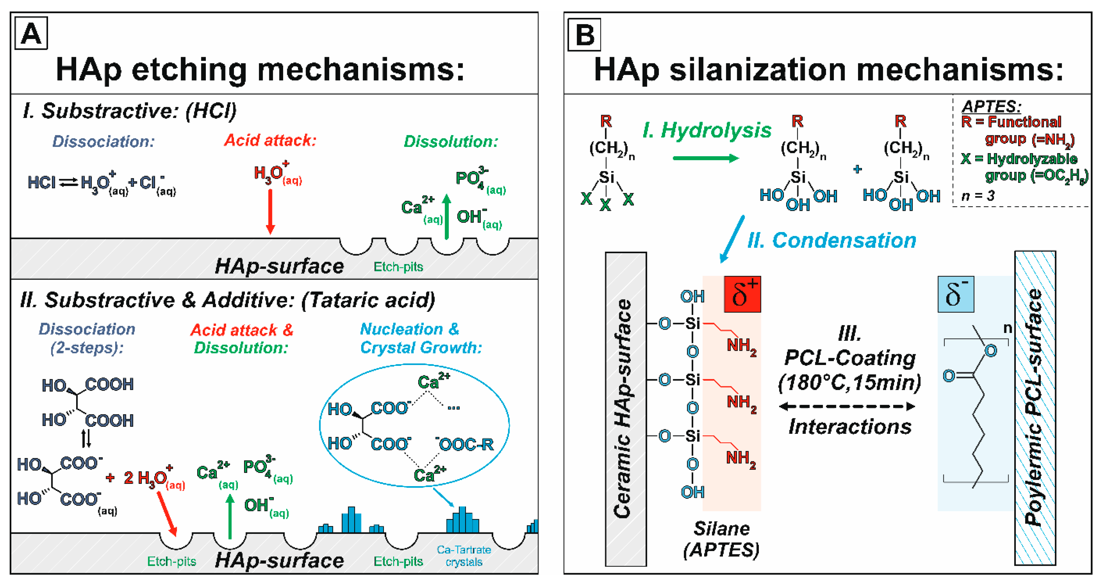
3.2. Microstructural Characterization of the Micro- and Nano-Surface-Textured HAp Ceramics
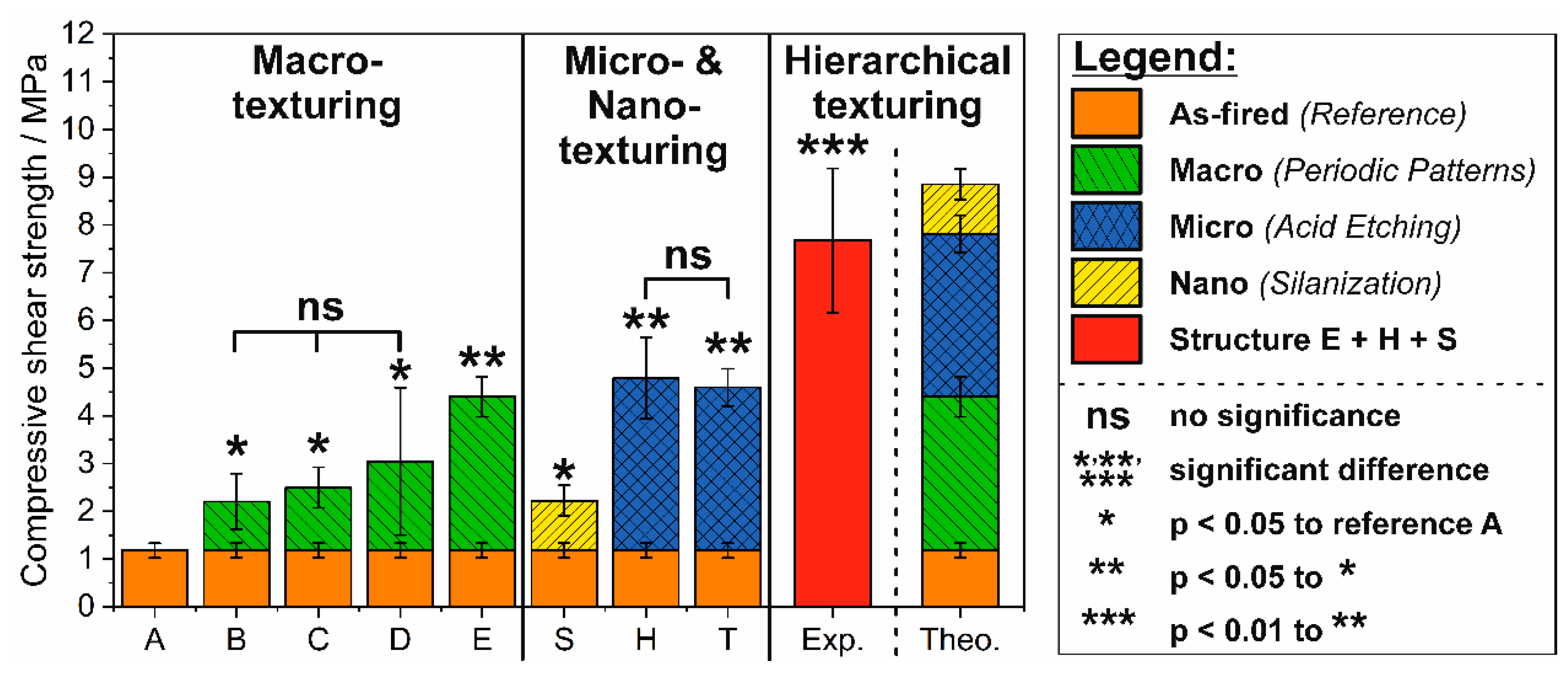
3.3. Adhesive Bonding Strength of Hierarchical Surface-Textured HAp to PCL
4. Conclusions
Author Contributions
Funding
Conflicts of Interest
References
- De Blas Romero, A.; Pfaffinger, M.; Mitteramskogler, G.; Schwentenwein, M.; Jellinek, C.; Homa, J.; Díaz Lantada, A.; Stampfl, J. Lithography-based additive manufacture of ceramic biodevices with design-controlled surface topographies. Int. J. Adv. Manuf. Technol. 2017, 88, 1547–1555. [Google Scholar] [CrossRef] [Green Version]
- Boyan, B. Role of material surfaces in regulating bone and cartilage cell response. Biomaterials 1996, 17, 137–146. [Google Scholar] [CrossRef]
- Curodeau, A.; Sachs, E.; Caldarise, S. Design and fabrication of cast orthopedic implants with freeform surface textures from 3-D printed ceramic shell. J. Biomed. Mater. Res. 2000, 53, 525–535. [Google Scholar] [CrossRef]
- Rupp, F.; Gittens, R.A.; Scheideler, L.; Marmur, A.; Boyan, B.D.; Schwartz, Z.; Geis-Gerstorfer, J. A review on the wettability of dental implant surfaces I: Theoretical and experimental aspects. Acta Biomater. 2014, 10, 2894–2906. [Google Scholar] [CrossRef] [Green Version]
- Jemat, A.; Ghazali, M.J.; Razali, M.; Otsuka, Y. Surface Modifications and Their Effects on Titanium Dental Implants. Biomed Res. Int. 2015, 2015, 791725. [Google Scholar] [CrossRef] [Green Version]
- Lee, J.W.; Chae, S.; Oh, S.; Kim, S.H.; Choi, K.H.; Meeseepong, M.; Chang, J.; Kim, N.; Yong, H.K.; Lee, N.-E.; et al. Single-Chain Atomic Crystals as Extracellular Matrix-Mimicking Material with Exceptional Biocompatibility and Bioactivity. Nano Lett. 2018, 18, 7619–7627. [Google Scholar] [CrossRef]
- Deligianni, D.D.; Katsala, N.D.; Koutsoukos, P.G.; Missirlis, Y.F. Effect of surface roughness of hydroxyapatite on human bone marrow cell adhesion, proliferation, differentiation and detachment strength. Biomaterials 2000, 22, 87–96. [Google Scholar] [CrossRef]
- Gui, N.; Xu, W.; Myers, D.E.; Shukla, R.; Tang, H.P.; Qian, M. The effect of ordered and partially ordered surface topography on bone cell responses: A review. Biomater. Sci. 2018, 6, 250–264. [Google Scholar] [CrossRef]
- Kunert-Keil, C.; Gredes, T.; Richter, D.-U.; Szyba, M.; Dominiak, M.; Gedrange, T. The survival and proliferation of fibroblasts on ceramic implants: An in vitro study. Biomed. Tech. 2012, 57, 11–15. [Google Scholar] [CrossRef]
- Wassmann, T.; Kreis, S.; Behr, M.; Buergers, R. The influence of surface texture and wettability on initial bacterial adhesion on titanium and zirconium oxide dental implants. Int. J. Implant Dent. 2017, 3, 32. [Google Scholar] [CrossRef]
- Danzer, R. Some notes on the correlation between fracture and defect statistics: Are Weibull statistics valid for very small specimens? J. Eur. Ceram. Soc. 2006, 26, 3043–3049. [Google Scholar] [CrossRef]
- Rice, R.W.; Mecholsky, J.J.; Freiman, S.W.; Morey, S.M. Failure Causing Defects in Ceramics: What NDE Should Find; Defense Technical Information Center: Fort Belvoir, VA, USA, 1979. [Google Scholar]
- Ghosh, S.; Abanteriba, S. Status of surface modification techniques for artificial hip implants. Sci. Technol. Adv. Mater. 2016, 17, 715–735. [Google Scholar] [CrossRef] [PubMed] [Green Version]
- Kim, Y.-H.; Ritchie, A.; Hardaker, C. Surface roughness of ceramic femoral heads after in vivo transfer of metal: Correlation to polyethylene wear. J. Bone Joint Surg. Am. 2005, 87, 577–582. [Google Scholar] [CrossRef] [PubMed]
- Roy, T.; Choudhury, D.; Ghosh, S.; Bin Mamat, A.; Pingguan-Murphy, B. Improved friction and wear performance of micro dimpled ceramic-on-ceramic interface for hip joint arthroplasty. Ceram. Int. 2015, 41, 681–690. [Google Scholar] [CrossRef]
- Schneider, J.; Djamiykov, V.; Greiner, C. Friction reduction through biologically inspired scale-like laser surface textures. Beilstein J. Nanotechnol. 2018, 9, 2561–2572. [Google Scholar] [CrossRef] [PubMed]
- Demirtag, Z.; Culhaoglu, A.K. Surface Roughness of Ceramic-Resin Composites After Femtosecond Laser Irradiation, Sandblasting or Acid Etching and Their Bond Strength With and Without Silanization to a Resin Cement. Oper. Dent. 2019, 44, 156–167. [Google Scholar] [CrossRef] [PubMed]
- Kern, M.; Wegner, S.M. Bonding to zirconia ceramic: Adhesion methods and their durability. Dent. Mater. 1998, 14, 64–71. [Google Scholar] [CrossRef]
- Piascik, J.R.; Wolter, S.D.; Stoner, B.R. Development of a novel surface modification for improved bonding to zirconia. Dent. Mater. 2011, 27, e99–e105. [Google Scholar] [CrossRef]
- Thompson, J.Y.; Stoner, B.R.; Piascik, J.R.; Smith, R. Adhesion/cementation to zirconia and other non-silicate ceramics: Where are we now? Dent. Mater. 2011, 27, 71–82. [Google Scholar] [CrossRef] [Green Version]
- Xu, S.L.; Nishikawa, C.; Shimada, K.; Mizutani, M.; Kuriyagawa, T. Surface Textures Fabrication on Zirconia Ceramics by 3D Ultrasonic Vibration Assisted Slant Feed Grinding. AMR 2013, 797, 326–331. [Google Scholar] [CrossRef]
- Bettinger, C.J.; Langer, R.; Borenstein, J.T. Engineering substrate topography at the micro- and nanoscale to control cell function. Angew. Chem. Int. Ed. Engl. 2009, 48, 5406–5415. [Google Scholar] [CrossRef] [PubMed] [Green Version]
- Ashby, M.F.; Bréchet, Y. Designing hybrid materials. Acta Mater. 2003, 51, 5801–5821. [Google Scholar] [CrossRef]
- Dorozhkin, S.V. Biocomposites and hybrid biomaterials based on calcium orthophosphates. Biomatter 2011, 1, 3–56. [Google Scholar] [CrossRef] [PubMed] [Green Version]
- Xiao, X.; Liu, R.; Huang, Q.; Ding, X. Preparation and characterization of hydroxyapatite/polycaprolactone-chitosan composites. J. Mater. Sci. Mater. Med. 2009, 20, 2375–2383. [Google Scholar] [CrossRef] [PubMed]
- Wong, S.-C.; Baji, A. Fracture strength and adhesive strength of hydroxyapatite-filled polycaprolactone. J. Mater. Sci. Mater. Med. 2008, 19, 929–936. [Google Scholar] [CrossRef]
- Ródenas-Rochina, J.; Ribelles, J.L.G.; Lebourg, M. Comparative study of PCL-HAp and PCL-bioglass composite scaffolds for bone tissue engineering. J. Mater. Sci. Mater. Med. 2013, 24, 1293–1308. [Google Scholar] [CrossRef]
- Neuendorf, R.E.; Saiz, E.; Tomsia, A.P.; Ritchie, R.O. Adhesion between biodegradable polymers and hydroxyapatite: Relevance to synthetic bone-like materials and tissue engineering scaffolds. Acta Biomater. 2008, 4, 1288–1296. [Google Scholar] [CrossRef]
- Kim, J.-W.; Shin, K.-H.; Koh, Y.-H.; Hah, M.J.; Moon, J.; Kim, H.-E. Production of Poly(ε-Caprolactone)/Hydroxyapatite Composite Scaffolds with a Tailored Macro/Micro-Porous Structure, High Mechanical Properties, and Excellent Bioactivity. Materials 2017, 10, 1123. [Google Scholar] [CrossRef] [Green Version]
- Chuenjitkuntaworn, B.; Inrung, W.; Damrongsri, D.; Mekaapiruk, K.; Supaphol, P.; Pavasant, P. Polycaprolactone/hydroxyapatite composite scaffolds: Preparation, characterization, and in vitro and in vivo biological responses of human primary bone cells. J. Biomed. Mater. Res. A 2010, 94, 241–251. [Google Scholar] [CrossRef]
- Antony, B.-F.; Amyl, G. Novel high-strength bioabsorbable bone adhesives. Front. Bioeng. Biotechnol. 2016, 4. [Google Scholar] [CrossRef]
- Bride, J.A.; Baskaran, S.; Taylor, N.; Halloran, J.W.; Juan, W.H.; Pang, S.W.; O’Donnell, M. Photolithographic micromolding of ceramics using plasma etched polyimide patterns. Appl. Phys. Lett. 1993, 63, 3379–3381. [Google Scholar] [CrossRef] [Green Version]
- Martin, C.R.; Aksay, I.A. Microchannel Molding: A Soft Lithography-inspired Approach to Micrometer-scale Patterning. J. Mater. Res. 2005, 20, 1995–2003. [Google Scholar] [CrossRef]
- Jedlicka, S.S.; McKenzie, J.L.; Leavesley, S.J.; Little, K.M.; Webster, T.J.; Robinson, J.P.; Nivens, D.E.; Rickus, J.L. Sol-gel derived materials as substrates for neuronal differentiation: Effects of surface features and protein conformation. J. Mater. Chem. 2006, 16, 3221. [Google Scholar] [CrossRef]
- Stumpf, M.; Travitzky, N.; Greil, P.; Fey, T. Sol-gel infiltration of complex cellular indirect 3D printed alumina. J. Eur. Ceram. Soc. 2018, 38, 3603–3609. [Google Scholar] [CrossRef]
- Hermanson, G.T. Silane coupling agents. In Bioconjugate Techniques; Elsevier: Amsterdam, The Netherlands, 2013; pp. 535–548. ISBN 9780123822390. [Google Scholar]
- Biggemann, J.; Pezoldt, M.; Stumpf, M.; Greil, P.; Fey, T. Modular ceramic scaffolds for individual implants. Acta Biomater. 2018, 80, 390–400. [Google Scholar] [CrossRef]
- Biggemann, J.; Hoffmann, P.; Hristov, I.; Simon, S.; Müller, P.; Fey, T. Injection Molding of 3-3 Hydroxyapatite Composites. Materials 2020, 13, 1907. [Google Scholar] [CrossRef] [PubMed] [Green Version]
- Biggemann, J.; Diepold, B.; Pezoldt, M.; Stumpf, M.; Greil, P.; Fey, T. Automated 3D assembly of periodic alumina-epoxy composite structures. J. Am. Ceram. Soc. 2018, 101, 3864–3873. [Google Scholar] [CrossRef]
- Sahaya Shajan, X.; Mahadevan, C. FT-IR spectroscopic and thermal studies on pure and impurity added calcium tartrate tetrahydrate crystals. Cryst. Res. Technol. 2005, 40, 598–602. [Google Scholar] [CrossRef]
- Schuessele, A.; Mayr, H.; Tessmar, J.; Goepferich, A. Enhanced bone morphogenetic protein-2 performance on hydroxyapatite ceramic surfaces. J. Biomed. Mater. Res. A 2009, 90, 959–971. [Google Scholar] [CrossRef]
- German Institute of Standardization E.V. Geometrical Product Specifications (GPS)—Surface Texture: Profile Method—Terms, Definitions and Surface Texture Parameters; DIN EN ISO 4287:2010-07; Beuth Verlag GmbH: Berlin, Germany, 2010. [Google Scholar]
- German Institute of Standardization E.V. Geometrical Product Specifications (GPS)—Surface Texture: Profile Method—Rules and Procedures for the Assessment of Surface Texture; DIN EN ISO 4288:1998-04; Beuth Verlag GmbH: Berlin, Germany, 1998. [Google Scholar]
- German Institute of Standardization E.V. Beschichtungsstoffe—Benetzbarkeit—Teil2: Bestimmung der Freien Oberflächenenergie Fester Oberflächen durch Messung des Kontaktwinkels; DIN 55660-2:2011-12; Beuth Verlag GmbH: Berlin, Germany, 2011. [Google Scholar]
- German Institute of Standardization E.V. Adhesives—Wettability—Determination by Measurement of Contact Angle and Surface Free Energy of Solid Surface; DIN EN 828:2013-04; Beuth Verlag GmbH: Berlin, Germany, 2013. [Google Scholar]
- Van Oss, C.; Good, R.; Chaudhury, M. The role of van der Waals forces and hydrogen bonds in “hydrophobic interactions” between biopolymers and low energy surfaces. J. Colloid Interface Sci. 1986, 111, 378–390. [Google Scholar] [CrossRef]
- Van Oss, C.J.; Good, R.J.; Chaudhury, M.K. Additive and nonadditive surface tension components and the interpretation of contact angles. Langmuir 1988, 4, 884–891. [Google Scholar] [CrossRef]
- Hefer, A.W.; Bhasin, A.; Little, D.N. Bitumen Surface Energy Characterization Using a Contact Angle Approach. J. Mater. Civ. Eng. 2006, 18, 759–767. [Google Scholar] [CrossRef]
- German Institute of Standardization E.V. Adhesives—Determination of Tensile Lap-Shear Strength of Bonded Assemblies, German Version EN 1465:2009; DIN EN 1465:2009-07; Beuth Verlag GmbH: Berlin, Germany, 2009. [Google Scholar]
- German Institute of Standardization E.V. Adhesives—Determination of Shear Behaviour of Structural Adhesives—Part 2: Tensile Test Method Using Thick Adherends; ISO 11003-2:2019-06; Beuth Verlag GmbH: Berlin, Germany, 2019. [Google Scholar]
- George, E.; Liacouras, P.; Rybicki, F.J.; Mitsouras, D. Measuring and Establishing the Accuracy and Reproducibility of 3D Printed Medical Models. Radiographics 2017, 37, 1424–1450. [Google Scholar] [CrossRef] [PubMed]
- Toth, T.; Hudak, R.; Zivcak, J. Dimensional verification and quality control of implants produced by additive manufacturing. Qual. Innov. Prosper. J. 2015, 19. [Google Scholar] [CrossRef] [Green Version]
- Habenicht, G. Kleben; Springer: Berlin/Heidelberg, Germany, 2009; ISBN 978-3-540-85264-3. [Google Scholar]
- Fischer, H.; Niedhart, C.; Kaltenborn, N.; Prange, A.; Marx, R.; Niethard, F.U.; Telle, R. Bioactivation of inert alumina ceramics by hydroxylation. Biomaterials 2005, 26, 6151–6157. [Google Scholar] [CrossRef]
- Dorozhkin, S.V. Dissolution mechanism of calcium apatites in acids: A review of literature. World J. Methodol. 2012, 2, 1–17. [Google Scholar] [CrossRef]
- Yoshida, Y.; van Meerbeek, B.; Nakayama, Y.; Yoshioka, M.; Snauwaert, J.; Abe, Y.; Lambrechts, P.; Vanherle, G.; Okazaki, M. Adhesion to and decalcification of hydroxyapatite by carboxylic acids. J. Dent. Res. 2001, 80, 1565–1569. [Google Scholar] [CrossRef]
- Naidu, S.; Blair, J.; Scherer, G.W.; Butt, D. Acid-Resistant Coatings on Marble. J. Am. Ceram. Soc. 2016, 99, 3421–3428. [Google Scholar] [CrossRef]
- Fu, B.; Shen, Q.; Qian, W.; Zeng, Y.; Sun, X.; Hannig, M. Interfacial interaction of tartaric acid with hydroxyapatite and enamel. J. Mater. Sci. Mater. Med. 2005, 16, 827–831. [Google Scholar] [CrossRef]
- Yoshida, Y.; van Meerbeek, B.; Nakayama, Y.; Snauwaert, J.; Hellemans, L.; Lambrechts, P.; Vanherle, G.; Wakasa, K. Evidence of chemical bonding at biomaterial-hard tissue interfaces. J. Dent. Res. 2000, 79, 709–714. [Google Scholar] [CrossRef]
- Aoyagi, Y.; Yamashita, K.; Doi, Y. Thermal degradation of poly((R)-3-hydroxybutyrate), poly(ε-caprolactone), and poly((S)-lactide). Polym. Degrad. Stabil. 2002, 76, 53–59. [Google Scholar] [CrossRef]
- Liu, Y.; Fang, Y.; Qian, J.; Liu, Z.; Yang, B.; Wang, X. Bio-inspired polydopamine functionalization of carbon fiber for improving the interfacial adhesion of polypropylene composites. RSC Adv. 2015, 5, 107652–107661. [Google Scholar] [CrossRef]
- Persenaire, O.; Alexandre, M.; Degée, P.; Dubois, P. Mechanisms and kinetics of thermal degradation of poly(epsilon-caprolactone). Biomacromolecules 2001, 2, 288–294. [Google Scholar] [CrossRef] [PubMed]
- Erbil, H.Y.; Yaşar, B.; Süzer, Ş.; Baysal, B.M. Surface Characterization of the Hydroxy-Terminated Poly(ε-caprolactone)/Poly(dimethylsiloxane) Triblock Copolymers by Electron Spectroscopy for Chemical Analysis and Contact Angle Measurements. Langmuir 1997, 13, 5484–5493. [Google Scholar] [CrossRef]
- Demnati, I.; Grossin, D.; Errassifi, F.; Combes, C.; Rey, C.; le Bolay, N. Synthesis of fluor-hydroxyapatite powder for plasma sprayed biomedical coatings: Characterization and improvement of the powder properties. Powder Technol. 2014, 255, 23–28. [Google Scholar] [CrossRef] [Green Version]
- González-Martín, M.L.; Labajos-Broncano, L.; Jańczuk, B.; Bruque, J.M. Wettability and surface free energy of zirconia ceramics and their constituent. J. Mater. Sci. 1999, 34, 5923–5926. [Google Scholar] [CrossRef]
- Wong, S.-C.; Baji, A.; Gent, A.N. Effect of specimen thickness on fracture toughness and adhesive properties of hydroxyapatite-filled polycaprolactone. Compos. Part A Appl. Sci. Manuf. 2008, 39, 579–587. [Google Scholar] [CrossRef]
- Duncan, B. Developments in testing adhesive joints. In Advances in Structural Adhesive Bonding: Developments in Testing Adhesive Joints; Duncan, B., Ed.; Elsevier: Amsterdam, The Netherlands, 2010; pp. 389–436. ISBN 9781845694357. [Google Scholar]
- Moulds, R.J. Design and stress calculations for bonded joints. In Adhesives and Sealants—General Knowledge, Application Techniques, New Curing Techniques: Design and Stress Calculations for Bonded Joints; Moulds, R.J., Ed.; Elsevier: Amsterdam, The Netherlands, 2006; pp. 197–231. ISBN 9780080447087. [Google Scholar]
- Kim, W.-S.; Yun, I.-H.; Lee, J.-J.; Jung, H.-T. Evaluation of mechanical interlock effect on adhesion strength of polymer–metal interfaces using micro-patterned surface topography. Int. J. Adhes. Adhes. 2010, 30, 408–417. [Google Scholar] [CrossRef]
- Stuart, T.P.; Crouch, I.G. The design, testing and evaluation of adhesively bonded, interlocking, tapered joints between thick aluminium alloy plates. Int. J. Adhes. Adhes. 1992, 12, 3–8. [Google Scholar] [CrossRef]


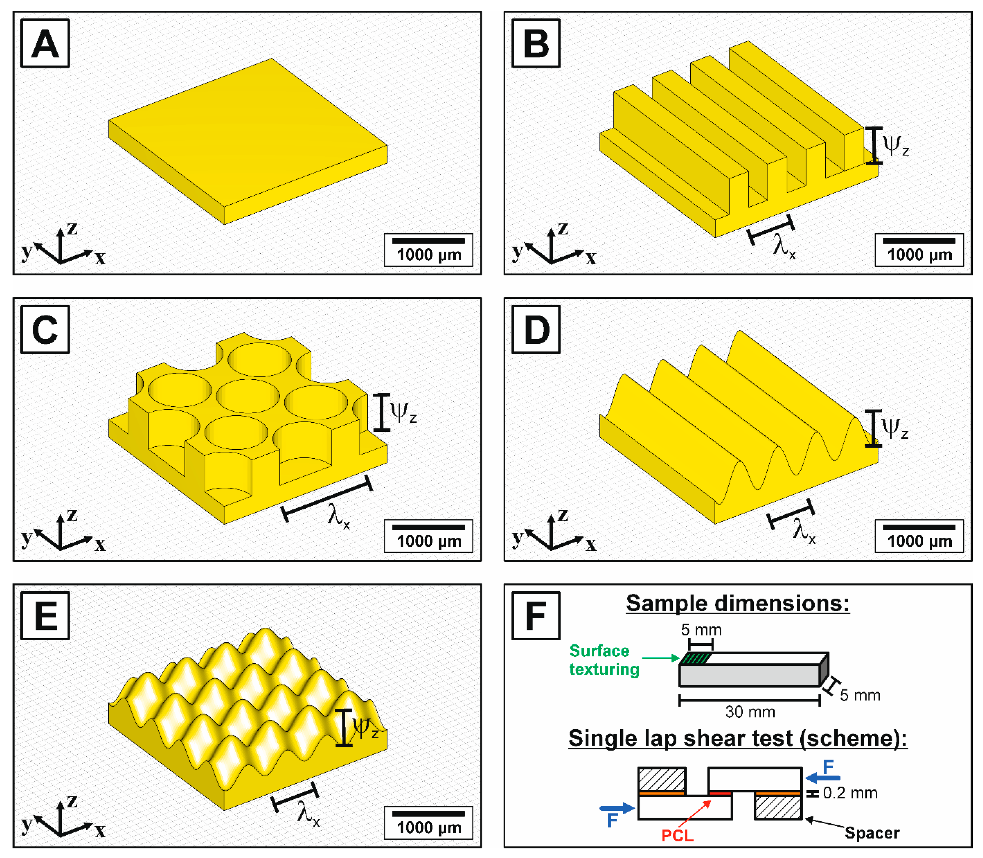
| Texturing Type | Surface Morphology | Structuring Spacing (Wavelength λ) | Structuring Depth (2 × Amplitude ψ) | Tested Surface Treatments | |
|---|---|---|---|---|---|
| λx | λy | Ψz | ** | ||
| /µm | /µm | /µm | |||
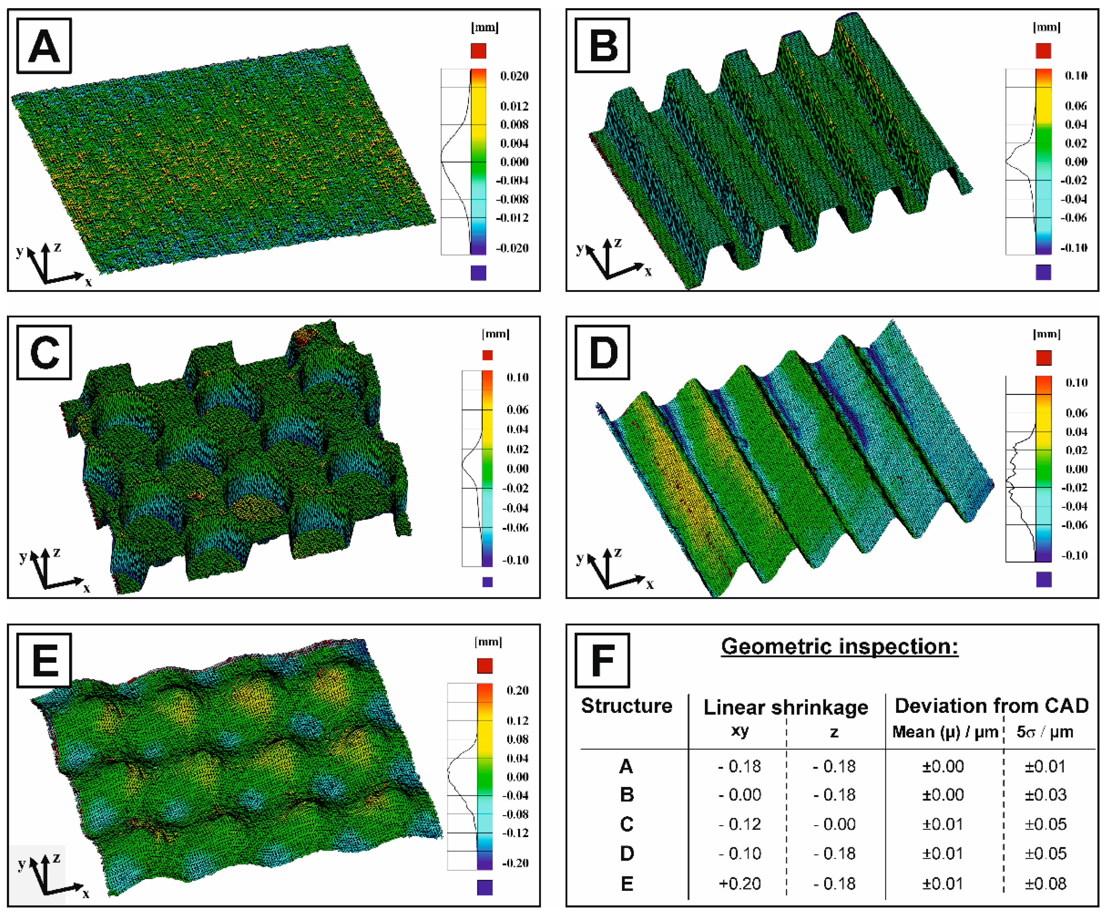
| A | Non-textured | - | - | 500 | F, P, H, T, S, T + S |
| B | Linear grooves | 550 | - | 500 | F |
| C | Cylindric pits | 1100 | 780 | 500 | F |
| D | Linear waves * | 550 | - | 500 | F |
| E | Gaussian hills * | 550 | 390 | 500 | F, H+S |
| Measuring Liquids | Reference | Surface Energies (γ) | |||
|---|---|---|---|---|---|
| γtot | γLW | γ+ | γ− | ||
| /mJ·m−2 | /mJ·m−2 | /mJ·m−2 | /mJ·m−2 | ||
| Distilled water (H2O) | [48] | 72.8 | 21.8 | 25.5 | 25.5 |
| Glycerol (C3H8O) | [48] | 64.0 | 34 | 3.92 | 57.4 |
| Diiodomethane (CH2I2) | [48] | 50.8 | 50.8 | 0 | 0 |
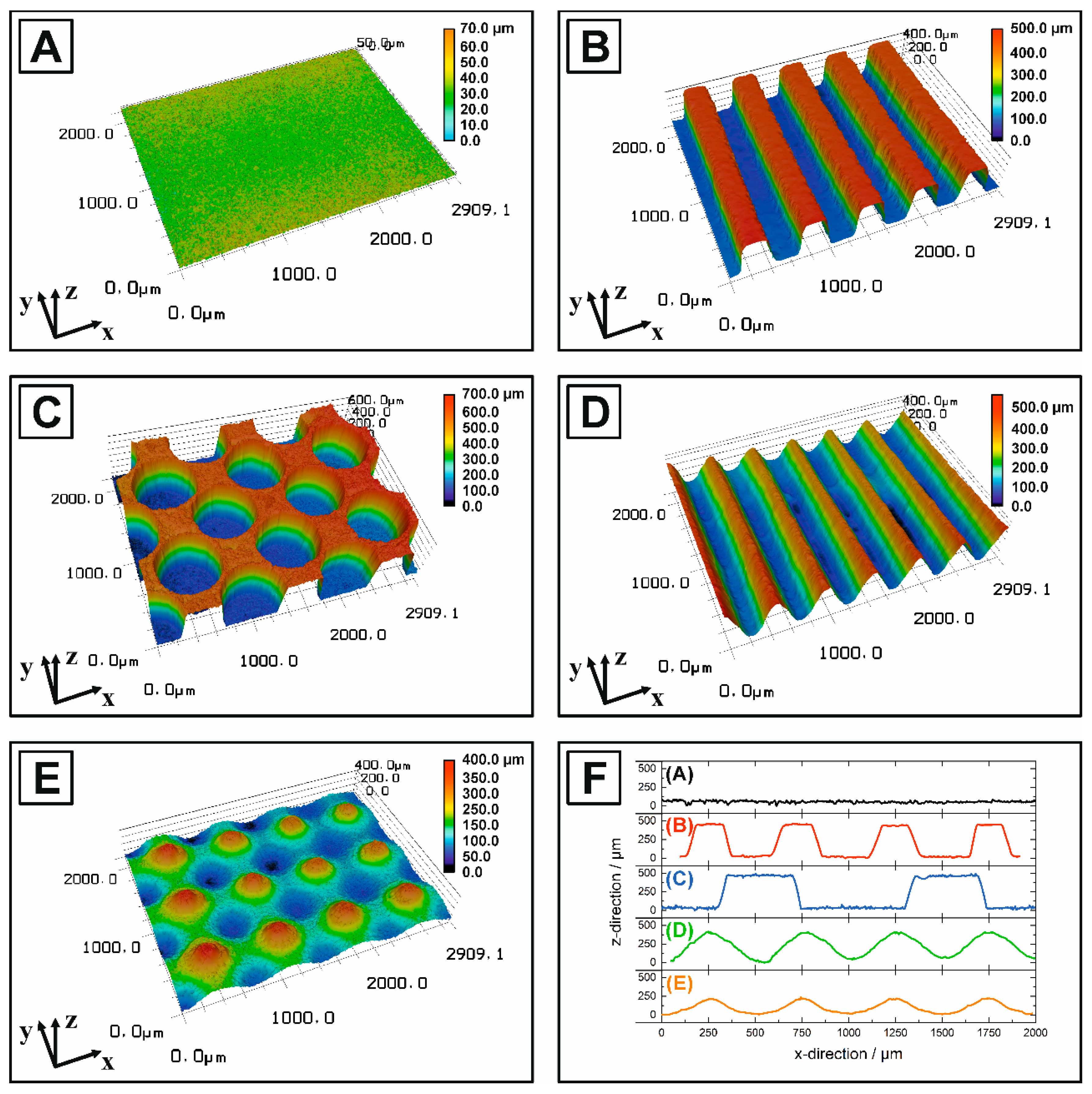
| Texturing Type | Surface Type/Surface Treatment | Roughness | Surface Coefficient SA *** | |||
|---|---|---|---|---|---|---|
| Ra | Rc | Rsm | Experimental | Theory | ||
| /µm | /µm | /µm | (real surface) | (CAD model) | ||
| Macrotexturing (micro molding) | * | * | * | * | ||
| A | Non-textured | 0.98 | 4.38 | 142.92 | 1.3 | 1.0 |
| B | Linear grooves | 190.47 | 463.67 | 470.66 | 3.3 | 2.8 |
| C | Cylindric pits | 203.96 | 499.72 | 946.47 | 3.5 | 2.78 |
| D | Linear waves | 123.46 | 428.47 | 486.71 | 2.4 | 2.06 |
| E | Gaussian hills | 87.22 | 295.08 | 479.10 | 1.7 | 1.66 |
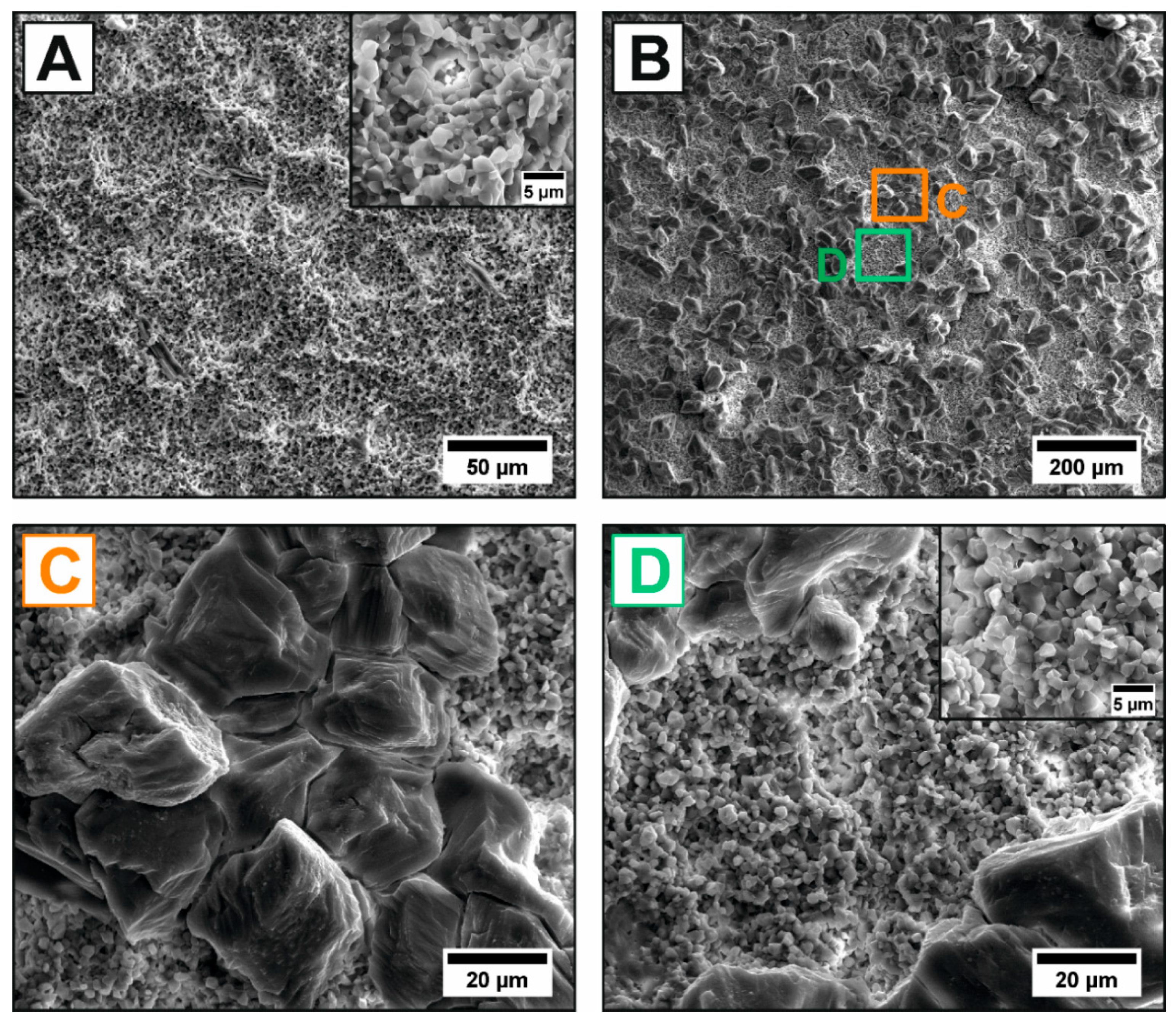
| Microtexturing (acid etching) | ** | ** | ** | ** | ||
| A | Polished (P) | 0.03 | 0.398 | 55.21 | 1.1 | 1.0 |
| A | HCl (H) | 2.93 | 13.57 | 175.92 | 2.2 | - |
| A | Tartaric acid (T) | 9.80 | 34.20 | 182.10 | 1.7 | - |
| Sample * | Surface Energies (γ) | Theoretical Adhesion Energy (PCL) | ||||
|---|---|---|---|---|---|---|
| γtot | γLW | γAB | γ+ | γ− | ||
| /mJ·m−2 | /mJ·m−2 | /mJ·m−2 | /mJ·m−2 | /mJ·m−2 | /mJ·m−2 | |
| Polished HAp (P) | 49.3 | 39.3 | 10.0 | 0.4 | 66.9 | 85.3 |
| Reference HAp [64] | 55.8 | 45.5 | 10.3 | 0.5 | 53.2 | - |
| Silanized (S) | 46.6 | 42.2 | 4.4 | 0.1 | 33.7 | 84.9 |
| HCl-etched (H) | 78.8 | 42.9 | 35.9 | 4.4 | 73.2 | 99.7 |
| Tartaric acid-etched (T) | 90.5 | 45.6 | 44.9 | 5.7 | 89.3 | 104.7 |
| T+S | 82.2 | 44.6 | 37.6 | 4.8 | 73.3 | 101.9 |
| PCL | 38.7 | 36.4 | 2.3 | 0.1 | 13.0 | - |
| Reference PCL [63] | 26.5 | 24.4 | 2.1 | 0.2 | 5.2 | - |
© 2020 by the authors. Licensee MDPI, Basel, Switzerland. This article is an open access article distributed under the terms and conditions of the Creative Commons Attribution (CC BY) license (http://creativecommons.org/licenses/by/4.0/).
Share and Cite
Biggemann, J.; Müller, P.; Köllner, D.; Simon, S.; Hoffmann, P.; Heik, P.; Lee, J.H.; Fey, T. Hierarchical Surface Texturing of Hydroxyapatite Ceramics: Influence on the Adhesive Bonding Strength of Polymeric Polycaprolactone. J. Funct. Biomater. 2020, 11, 73. https://0-doi-org.brum.beds.ac.uk/10.3390/jfb11040073
Biggemann J, Müller P, Köllner D, Simon S, Hoffmann P, Heik P, Lee JH, Fey T. Hierarchical Surface Texturing of Hydroxyapatite Ceramics: Influence on the Adhesive Bonding Strength of Polymeric Polycaprolactone. Journal of Functional Biomaterials. 2020; 11(4):73. https://0-doi-org.brum.beds.ac.uk/10.3390/jfb11040073
Chicago/Turabian StyleBiggemann, Jonas, Philipp Müller, David Köllner, Swantje Simon, Patrizia Hoffmann, Paula Heik, Jung Heon Lee, and Tobias Fey. 2020. "Hierarchical Surface Texturing of Hydroxyapatite Ceramics: Influence on the Adhesive Bonding Strength of Polymeric Polycaprolactone" Journal of Functional Biomaterials 11, no. 4: 73. https://0-doi-org.brum.beds.ac.uk/10.3390/jfb11040073