
Computational Contact Pressure Prediction of CoCrMo, SS 316L and Ti6Al4V Femoral Head against UHMWPE Acetabular Cup under Gait Cycle

 ,
,  , ,
, ,  , , , and
Abstract
:1. Introduction
2. Materials and Methods
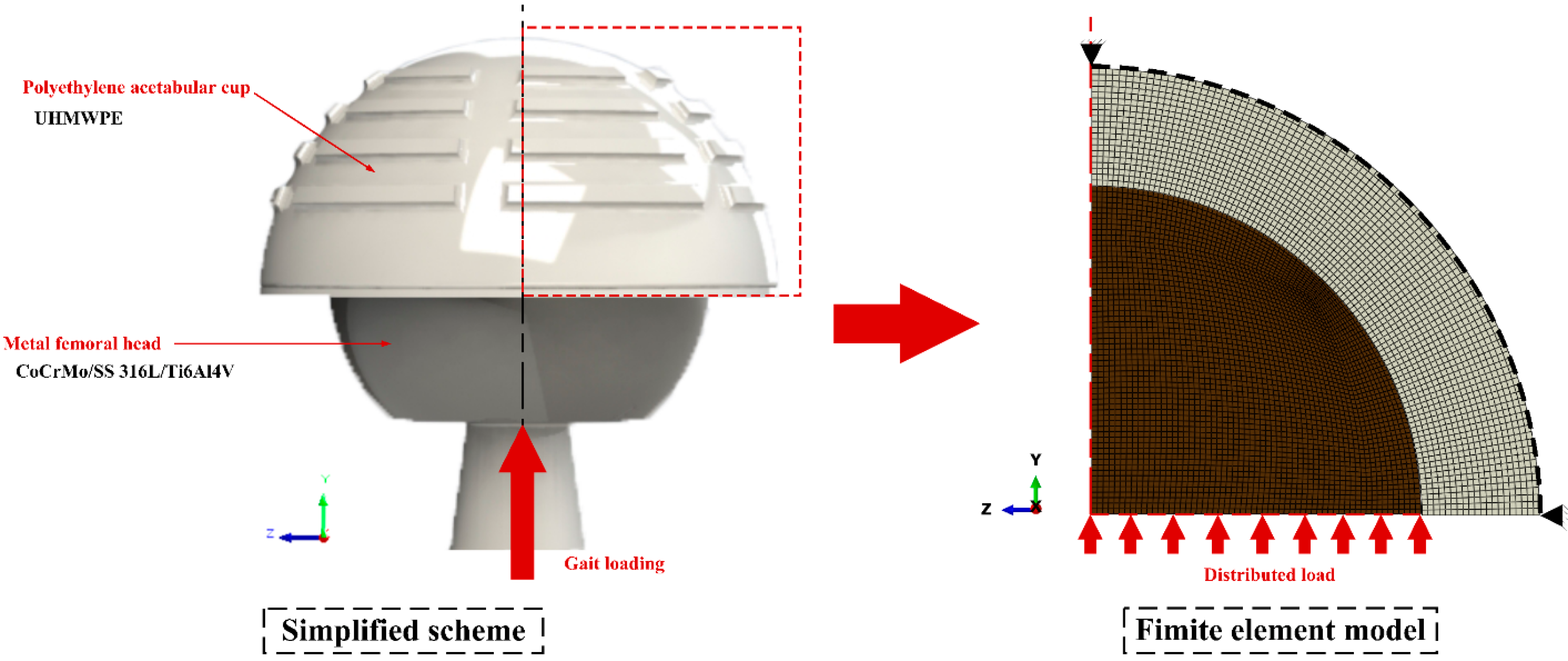
2.1. Finite Element Model
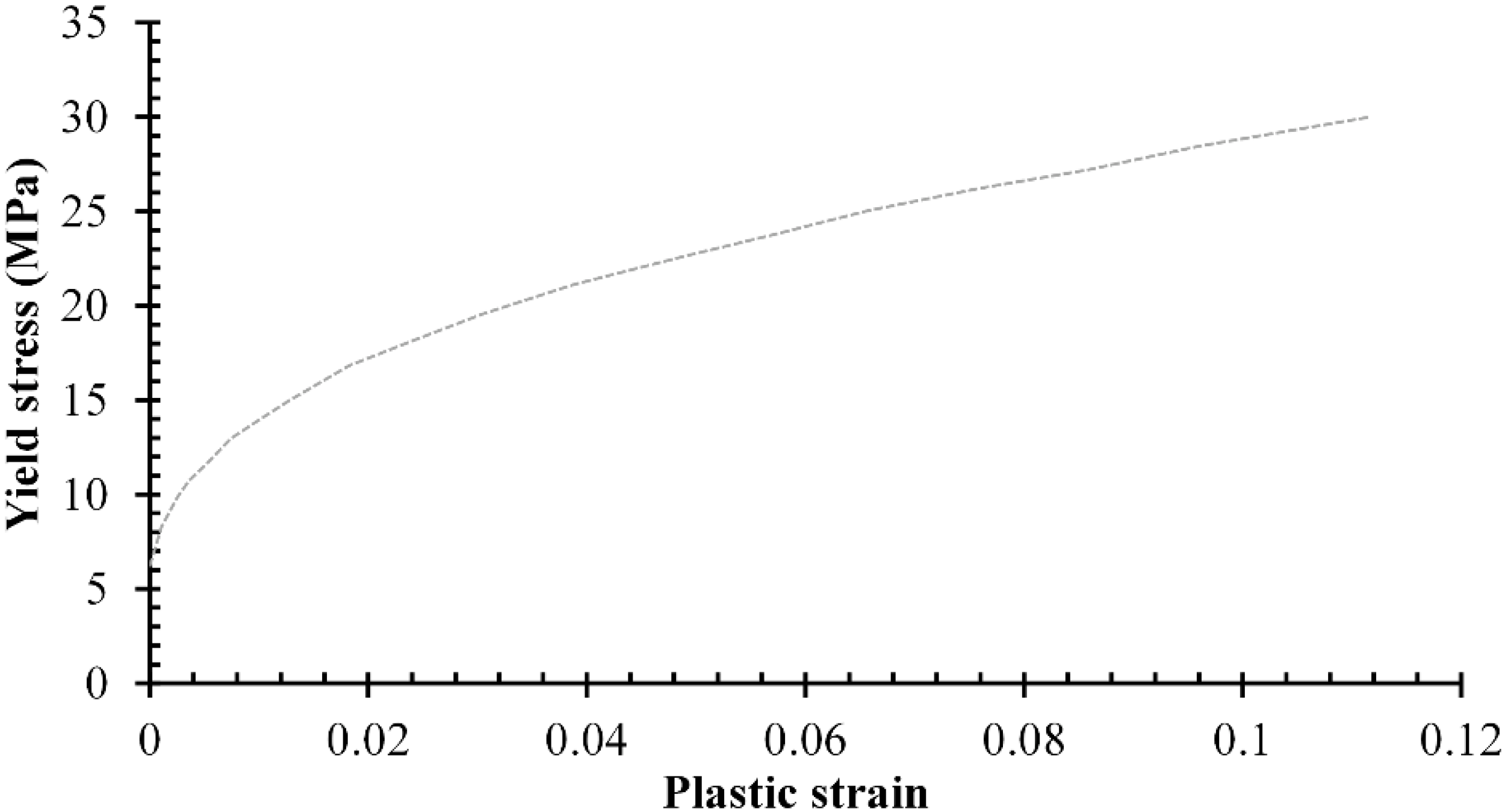
2.2. Materials Properties
2.3. Coefficient of Friction
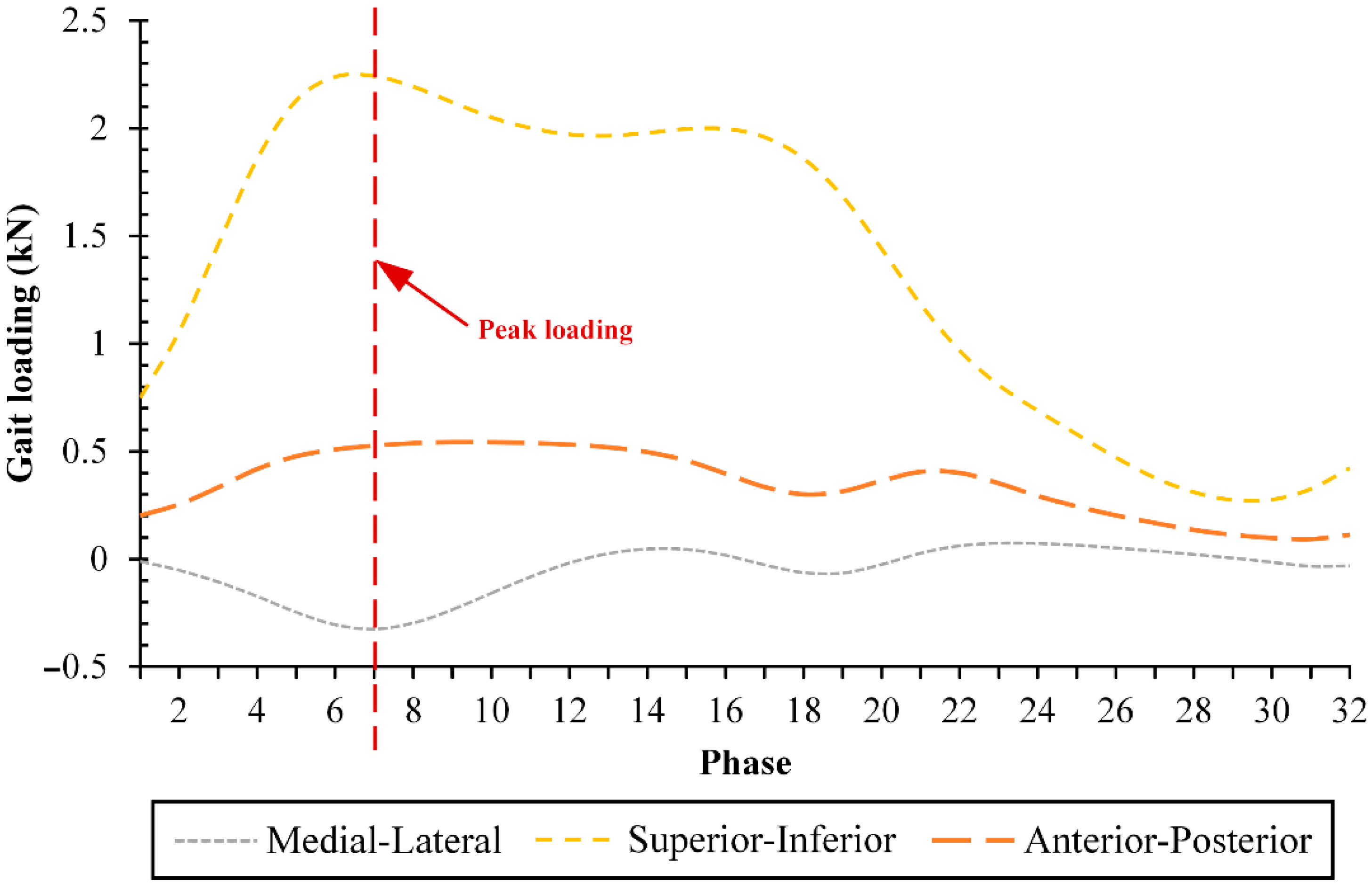
2.4. Gait Cycle
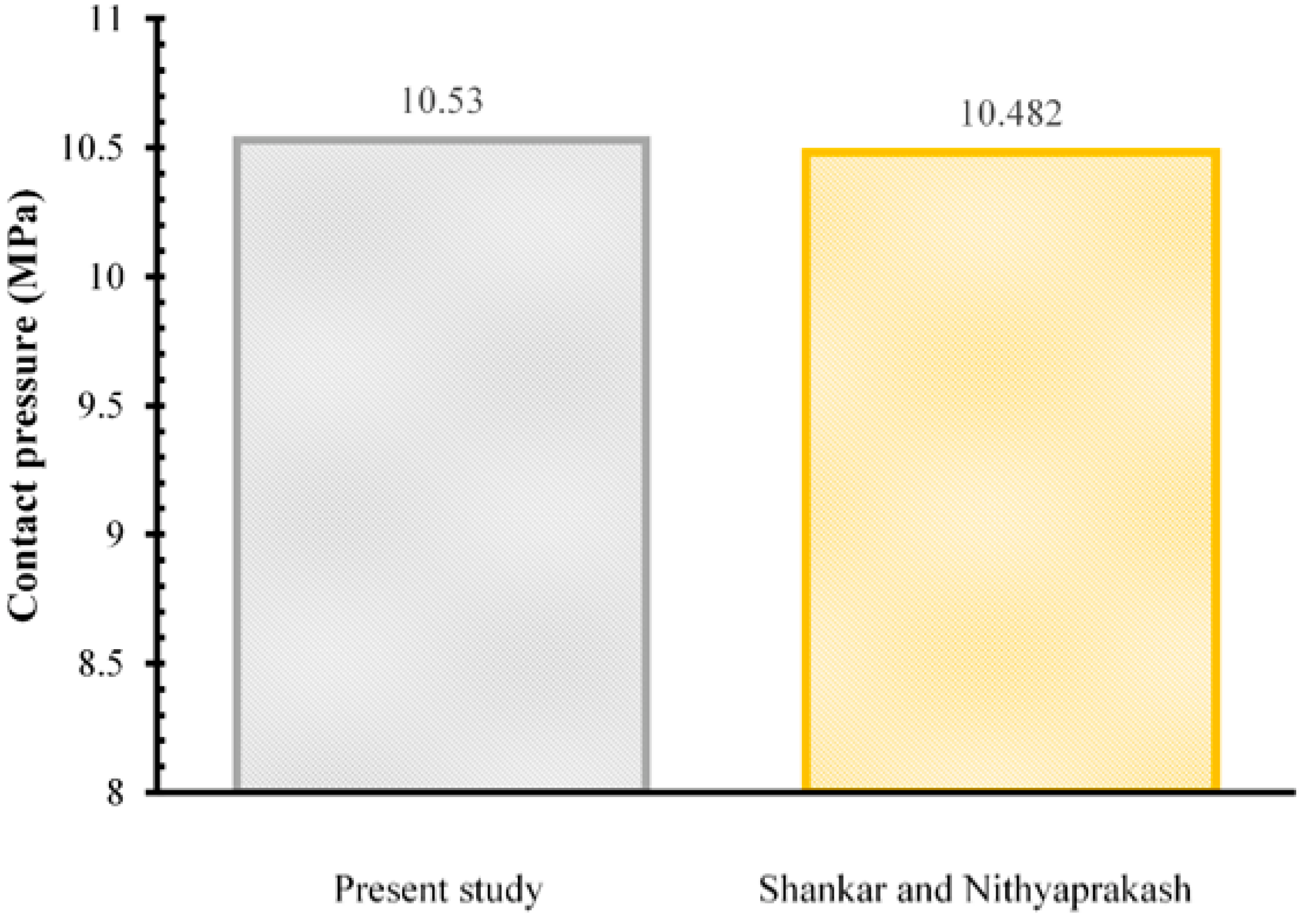
3. Results and Discussion
4. Conclusions
Author Contributions
Funding
Institutional Review Board Statement
Informed Consent Statement
Data Availability Statement
Acknowledgments
Conflicts of Interest
References
- EU—Indonesia Business Network. EIBN Sector Reports: Medical Devices, 2019 ed.; EU—Indonesia Business Network: Jakarta, Indonesia, 2019. [Google Scholar]
- Pozzuoli, A.; Berizzi, A.; Crimì, A.; Belluzzi, E.; Frigo, A.C.; de Conti, G.; Nicolli, A.; Trevisan, A.; Biz, C.; Ruggieri, P. Metal Ion Release, Clinical and Radiological Outcomes in Large Diameter Metal-on-Metal Total Hip Arthroplasty at Long-Term Follow-Up. Diagnostics 2020, 10, 941. [Google Scholar] [CrossRef] [PubMed]
- Australian Orthopaedic Association National Joint Replacement Registry. Annual Report 2020, 2020 ed.; Australian Orthopaedic Association: Adelaide, Australia, 2020. [Google Scholar]
- Pesce, V.; Maccagnano, G.; Vicenti, G.; Notarnicola, A.; Lovreglio, P.; Soleo, L.; Pantalone, A.; Salini, V.; Moretti, B. First Case Report of Vanadium Metallosis after Ceramic-on-Ceramic Total Hip Arthroplasty. J. Biol. Regul. Homeost. Agents 2013, 27, 1063–1068. [Google Scholar] [PubMed]
- Allizond, V.; Comini, S.; Cuffini, A.M.; Banche, G. Current Knowledge on Biomaterials for Orthopedic Applications Modified to Reduce Bacterial Adhesive Ability. Antibiotics 2022, 11, 529. [Google Scholar] [CrossRef] [PubMed]
- Nicolli, A.; Trevisan, A.; Bortoletti, I.; Pozzuoli, A.; Ruggieri, P.; Martinelli, A.; Gambalunga, A.; Carrieri, M. Biological Monitoring of Metal Ions Released from Hip Prostheses. Int. J. Environ. Res. Public Health 2020, 17, 3223. [Google Scholar] [CrossRef] [PubMed]
- Volpin, A.; Konan, S.; Biz, C.; Tansey, R.J.; Haddad, F.S. Reconstruction of Failed Acetabular Component in the Presence of Severe Acetabular Bone Loss: A Systematic Review. Musculoskelet. Surg. 2019, 103, 1–13. [Google Scholar] [CrossRef] [PubMed]
- Piconi, C.; Sprio, S. Oxide Bioceramic Composites in Orthopedics and Dentistry. J. Compos. Sci. 2021, 5, 206. [Google Scholar] [CrossRef]
- Aher, V.S.; Shirsat, U.M.; Wakchaure, V.D.; Venkatesh, M.A. An Experimental Investigation on Tribological Performance of UHMWPE Composite under Textured Dry Sliding Conditions. J. Tribol. 2020, 24, 110–125. [Google Scholar]
- Shahemi, N.; Liza, S.; Abbas, A.A.; Merican, A.M. Long-Term Wear Failure Analysis of Uhmwpe Acetabular Cup in Total Hip Replacement. J. Mech. Behav. Biomed. Mater. 2018, 87, 1–9. [Google Scholar] [CrossRef]
- Charlena, C.; Sukaryo, S.G.; Zuhfria, M.I. Hydroxyapatite Coating on Alloys CoCrMo-TiN with Sol-Gel Method. Indones. J. Fundam. Appl. Chem. 2016, 1, 55–60. [Google Scholar] [CrossRef] [Green Version]
- Dharmanto, D.; Supriadi, S.; Baskoro, A.S. Effect of Feed Metal Flow Rate on Low-Cost Plasma Atomizer for Fabricating 316L Stainless Steel Powder. Int. J. Technol. 2019, 10, 1593. [Google Scholar] [CrossRef] [Green Version]
- Qosim, N.; Supriadi, S.; Whulanza, Y.; Saragih, A.S. Development of Ti6Al-4V Based-Miniplate Manufactured by Electrical Discharge Machining as Maxillofacial Implant. J. Fundam. Appl. Sci. 2018, 10, 765–775. [Google Scholar]
- Reichelt, M.; Cappella, B. Comparative Analysis of Error Sources in the Determination of Wear Volumes of Oscillating Ball-on-Plane Tests. Front. Mech. Eng. 2020, 6, 25. [Google Scholar] [CrossRef]
- Akbar, I.; Prakoso, A.T.; Astrada, Y.M.; Sinaga, M.S.; Ammarullah, M.I.; Adanta, D.; Mataram, A.; Syahrom, A.; Jamari, J.; Basri, H. Permeability Study of Functionally Graded Scaffold Based on Morphology of Cancellous Bone. Malays. J. Med. Health Sci. 2021, 17 (Suppl. 13), 60–66. [Google Scholar]
- Lorkowski, J.; Pokorski, M. In Silico Finite Element Modeling of Stress Distribution in Osteosynthesis after Pertrochanteric Fractures. J. Clin. Med. 2022, 11, 1885. [Google Scholar] [CrossRef]
- Archard, J.F. Contact and Rubbing of Flat Surfaces. J. Appl. Phys. 1953, 24, 981–988. [Google Scholar] [CrossRef]
- Skvortsova, S.; Orlov, A.; Valyano, G.; Spektor, V.; Mamontova, N. Wear Resistance of Ti–6Al–4V Alloy Ball Heads for Use in Implants. J. Funct. Biomater. 2021, 12, 65. [Google Scholar] [CrossRef]
- Wang, L.; Williams, S.; Udofia, I.; Isaac, G.; Fisher, J.; Jin, Z. The Effect of Cup Orientation and Coverage on Contact Mechanics and Range of Motion of Metal-on-Metal Hip Resurfacing Arthroplasty. Proc. Inst. Mech. Eng. Part H J. Eng. Med. 2012, 226, 877–886. [Google Scholar] [CrossRef]
- Mattei, L.; Di Puccio, F. Wear Simulation of Metal-on-Metal Hip Replacements with Frictional Contact. J. Tribol. 2013, 135, 021402. [Google Scholar] [CrossRef]
- Shankar, S.; Nithyaprakash, R. Predicting the Wear of Soft-on-Hard Bearing Couples for Human Hip Prosthesis Using Finite Element Concepts. J. Mech. Med. Biol. 2016, 16, 1650020. [Google Scholar] [CrossRef]
- Ammarullah, M.I.; Afif, I.Y.; Maula, M.I.; Winarni, T.I.; Tauviqirrahman, M.; Bayuseno, A.P.; Basri, H.; Syahrom, A.; Saad, A.P.M.; Jamari, J. 2D Computational Tresca Stress Prediction of CoCrMo-on-UHMWPE Bearing of Total Hip Prosthesis Based on Body Mass Index. Malays. J. Med. Health Sci. 2021, 17 (Suppl. 13), 18–21. [Google Scholar]
- Wu, J.; Taylor, D.; Forst, R.; Seehaus, F. Does Pelvic Orientation Influence Wear Measurement of the Acetabular Cup in Total Hip Arthroplasty—An Experimental Study. Appl. Sci. 2021, 11, 10014. [Google Scholar] [CrossRef]
- Jamari, J.; Ammarullah, M.I.; Saad, A.P.M.; Syahrom, A.; Uddin, M.; van der Heide, E.; Basri, H. The Effect of Bottom Profile Dimples on the Femoral Head on Wear in Metal-on-Metal Total Hip Arthroplasty. J. Funct. Biomater. 2021, 12, 38. [Google Scholar] [CrossRef] [PubMed]
- Ammarullah, M.I.; Afif, I.Y.; Maula, M.I.; Winarni, T.I.; Tauviqirrahman, M.; Akbar, I.; Basri, H.; Heide, E.; Van Der Jamari, J. Tresca Stress Simulation of Metal-on-Metal Total Hip Arthroplasty during Normal Walking Activity. Materials 2021, 14, 7554. [Google Scholar] [CrossRef]
- Ammarullah, M.I.; Afif, I.Y.; Maula, M.I.; Winarni, T.I.; Tauviqirrahman, M.; Jamari, J. Tresca Stress Evaluation of Metal-on-UHMWPE Total Hip Arthroplasty during Peak Loading from Normal Walking Activity. Mater. Today Proc. 2022; in press. [Google Scholar] [CrossRef]
- Gaval, V.R.; Solanke, S.G. Tribological Studies of Different Bioimplant Materials for Orthopaedic Application. ASM Sci. J. 2020, 13, 1–8. [Google Scholar] [CrossRef]
- Handoko, H.; Suyitno, S.; Dharmastiti, R.; Magetsari, R. Wear Prediction of UHMWPE Acetabular Cup against CP Titanium Femoral Head in a Hip Joint Simulator. IOP Conf. Ser. Mater. Sci. Eng. 2018, 384, 012018. [Google Scholar] [CrossRef]
- Andrysek, J.; Michelini, A.; Eshraghi, A.; Kheng, S.; Heang, T.; Thor, P. Gait Performance of Friction-Based Prosthetic Knee Joint Swing-Phase Controllers in Under-Resourced Settings. Prosthesis 2022, 4, 125–135. [Google Scholar] [CrossRef]
- Basri, H.; Syahrom, A.; Prakoso, A.T.; Wicaksono, D.; Amarullah, M.I.; Ramadhoni, T.S.; Nugraha, R.D. The Analysis of Dimple Geometry on Artificial Hip Joint to the Performance of Lubrication. J. Phys. Conf. Ser. 2019, 1198, 042012. [Google Scholar] [CrossRef]
- Dassault Systèmes. Abaqus Analysis User’s Guide Volume IV: Elements; Dassault Systèmes Simulia Corp.: Providence, RI, USA, 2016. [Google Scholar]
- Ali, S.; Abdul Rani, A.M.; Baig, Z.; Ahmed, S.W.; Hussain, G.; Subramaniam, K.; Hastuty, S.; Rao, T.V.V.L.N. Biocompatibility and Corrosion Resistance of Metallic Biomaterials. Corros. Rev. 2020, 38, 381–402. [Google Scholar] [CrossRef]
- Zaman, H.A.; Sharif, S.; Idris, M.H.; Kamarudin, A. Metallic Biomaterials for Medical Implant Applications: A Review. Appl. Mech. Mater. 2015, 735, 19–25. [Google Scholar] [CrossRef]
- Ammarullah, M.I.; Afif, I.Y.; Maula, M.I.; Winarni, T.I.; Tauviqirrahman, M.; Bayuseno, A.P.; Basri, H.; Syahrom, A.; Saad, A.P.M.; Jamari. Wear Analysis of Acetabular Cup on Metal-on-Metal Total Hip Arthroplasty with Dimple Addition Using Finite Element Method. AIP Conf. Proc. 2022, 2391, 020017. [Google Scholar] [CrossRef]
- Vendittoli, P.-A.; Martinov, S.; Morcos, M.W.; Sivaloganathan, S.; Blakeney, W.G. Personalized Hip Joint Replacement with Large Diameter Head: Current Concepts. J. Clin. Med. 2022, 11, 1918. [Google Scholar] [CrossRef] [PubMed]


| Component | Material | Young’s Modulus | Poisson’s Ratio | Reference |
|---|---|---|---|---|
| Femoral head | CoCrMo | 210 GPa | 0.3 | [24] |
| SS 316L | 193 GPa | [25] | ||
| Ti6Al4V | 110 GPa | [26] | ||
| Acetabular cup | UHMWPE | 1.4 GPa | [21] |
| Material’s Component | Coefficient of Friction | Reference | |
|---|---|---|---|
| Femoral Head | Acetabular Cup | ||
| CoCrMo | UHMWPE | 0.11 | [22] |
| SS 316L | UHMWPE | 0.1 | [26] |
| Ti6Al4V | UHMWPE | 0.0561 | [26] |
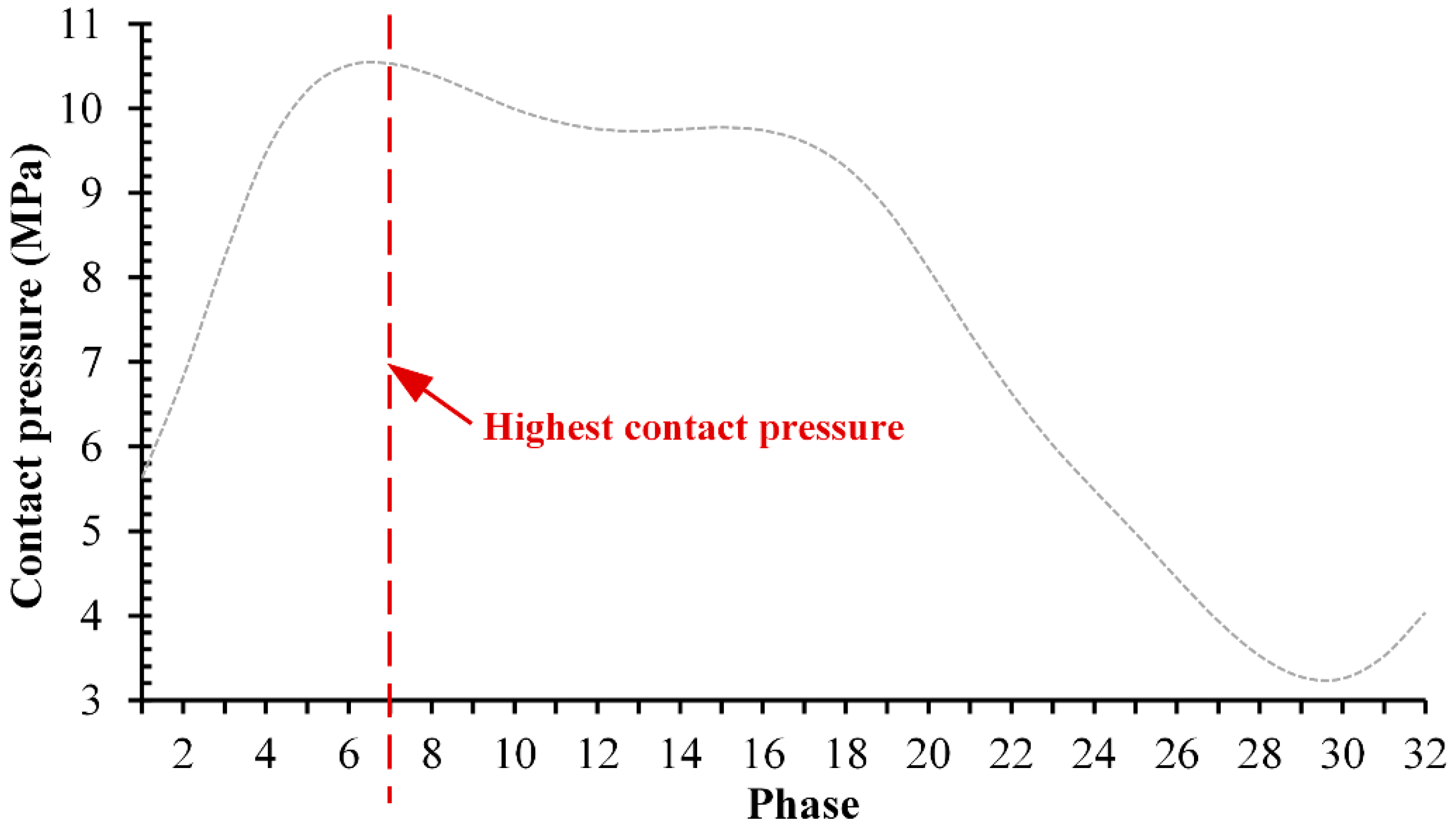
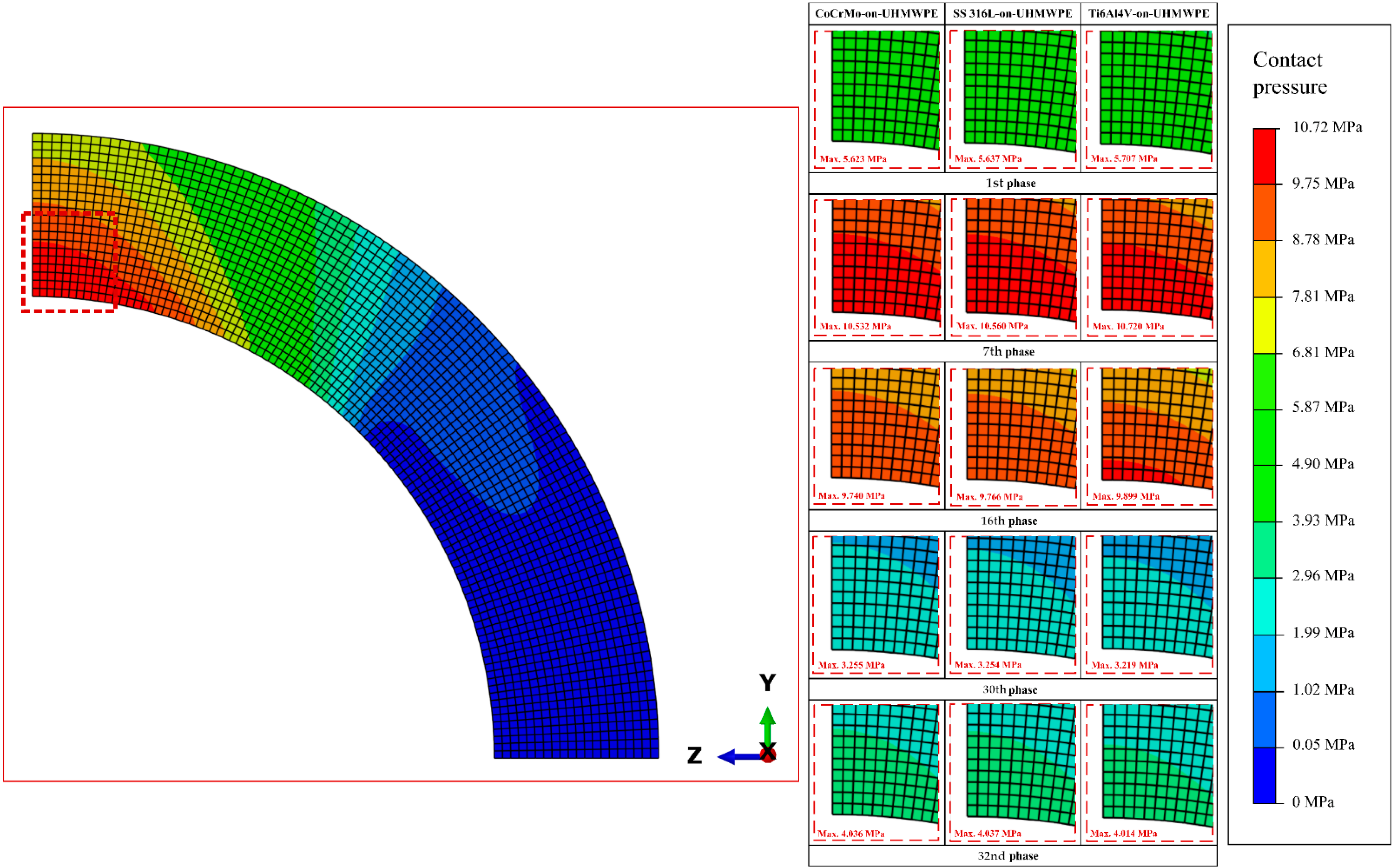
| Materials Combination | Contact Pressure |
|---|---|
| CoCrMo-on-UHMWPE | 10.532 MPa |
| SS 316L-on-UHMWPE | 10.560 MPa |
| Ti6Al4V-on-UHMWPE | 10.720 MPa |
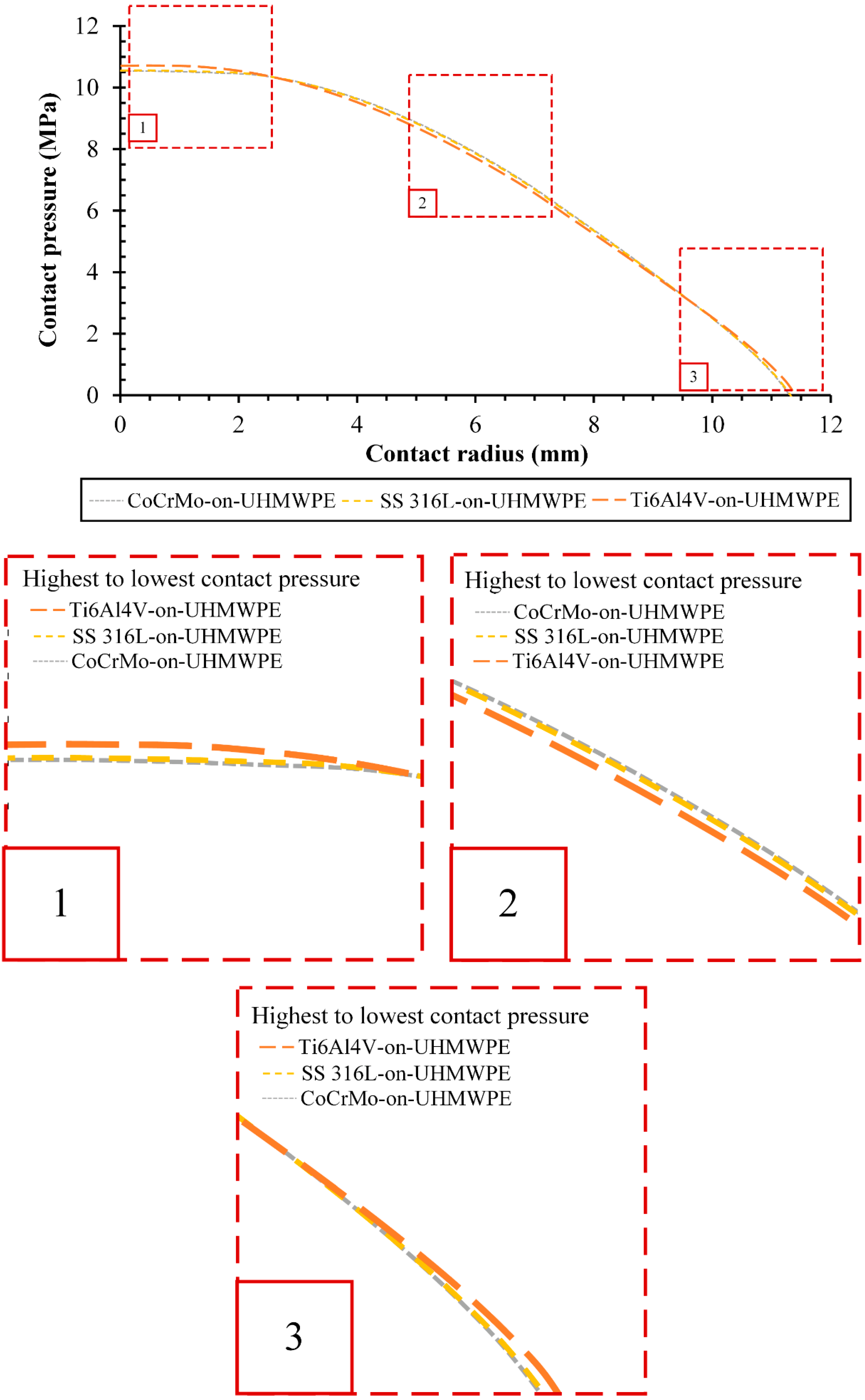
| Materials Combination | Contact Radius (mm) |
|---|---|
| CoCrMo-on-UHMWPE | 7.686 |
| SS 316L-on-UHMWPE | 7.608 |
| Ti6Al4V-on-UHMWPE | 7.590 |
| Materials Combination | Cumulative Contact Pressure (MPa) | Difference (MPa) | Comparison with Respective Maximum Contact Pressure (%) |
|---|---|---|---|
| CoCrMo-on-UHMWPE | 376.566 | 1.162 | 11.038 |
| SS 316L-on-UHMWPE | 376.432 | 1.028 | 9.740 |
| Ti6Al4V-on-UHMWPE | 375.404 | 0 | 0 |
Publisher’s Note: MDPI stays neutral with regard to jurisdictional claims in published maps and institutional affiliations. |
© 2022 by the authors. Licensee MDPI, Basel, Switzerland. This article is an open access article distributed under the terms and conditions of the Creative Commons Attribution (CC BY) license (https://creativecommons.org/licenses/by/4.0/).
Share and Cite
Jamari, J.; Ammarullah, M.I.; Santoso, G.; Sugiharto, S.; Supriyono, T.; Prakoso, A.T.; Basri, H.; van der Heide, E. Computational Contact Pressure Prediction of CoCrMo, SS 316L and Ti6Al4V Femoral Head against UHMWPE Acetabular Cup under Gait Cycle. J. Funct. Biomater. 2022, 13, 64. https://0-doi-org.brum.beds.ac.uk/10.3390/jfb13020064
Jamari J, Ammarullah MI, Santoso G, Sugiharto S, Supriyono T, Prakoso AT, Basri H, van der Heide E. Computational Contact Pressure Prediction of CoCrMo, SS 316L and Ti6Al4V Femoral Head against UHMWPE Acetabular Cup under Gait Cycle. Journal of Functional Biomaterials. 2022; 13(2):64. https://0-doi-org.brum.beds.ac.uk/10.3390/jfb13020064
Chicago/Turabian StyleJamari, J., Muhammad Imam Ammarullah, Gatot Santoso, S. Sugiharto, Toto Supriyono, Akbar Teguh Prakoso, Hasan Basri, and Emile van der Heide. 2022. "Computational Contact Pressure Prediction of CoCrMo, SS 316L and Ti6Al4V Femoral Head against UHMWPE Acetabular Cup under Gait Cycle" Journal of Functional Biomaterials 13, no. 2: 64. https://0-doi-org.brum.beds.ac.uk/10.3390/jfb13020064