
Optimization of Oxygen Evolution Reaction with Electroless Deposited Ni–P Catalytic Nanocoating

 ,
,  ,
,
Abstract
:
1. Introduction
2. Materials and Methods
2.1. Substrates
2.2. Preparation of Ni–P Catalysts
2.3. Characterization
2.4. Electrochemical Tests
3. Results and Discussion
4. Conclusions
Supplementary Materials
Author Contributions
Funding
Institutional Review Board Statement
Informed Consent Statement
Data Availability Statement
Acknowledgments
Conflicts of Interest
References
- Wu, D.; Kusada, K.; Yoshioka, S.; Yamamoto, T.; Toriyama, T.; Matsumura, S.; Chen, Y.; Seo, O.; Kim, J.; Song, C.; et al. Efficient overall water splitting in acid with anisotropic metal nanosheets. Nat. Commun. 2021, 12, 1145. [Google Scholar] [CrossRef]
- Landsmann, S.; Surace, Y.; Trottmann, M.; Dilger, S.; Weidenkaff, A.; Pokrant, S. Controlled design of functional nano-coatings: Reduction of loss mechanisms in photoelectrochemical water splitting. ACS Appl. Mater. Interfaces 2016, 8, 12149–12157. [Google Scholar] [CrossRef] [PubMed]
- Sun, H.; Xu, X.; Song, Y.; Zhou, W.; Shao, Z. Designing high-valence metal sites for electrochemical water splitting. Adv. Funct. Mater. 2021, 31, 2009779. [Google Scholar] [CrossRef]
- Zhou, Y.; Li, J.; Gao, X.; Chu, W.; Gao, G.; Wang, L.-W. Recent advances in single-atom electrocatalysts supported on two-dimensional materials for the oxygen evolution reaction. J. Mater. Chem. A 2021, 9, 9979–9999. [Google Scholar] [CrossRef]
- Liu, Y.; Li, Y.; Wu, Q.; Su, Z.; Wang, B.; Chen, Y.; Wang, S. Hollow CoP/FeP4 Heterostructural nanorods interwoven by CNT as a highly efficient electrocatalyst for oxygen evolution reactions. Nanomaterials 2021, 11, 1450. [Google Scholar] [CrossRef] [PubMed]
- Reier, T.; Oezaslan, M.; Strasser, P. Electrocatalytic oxygen evolution reaction (OER) on Ru, Ir, and Pt catalysts: A comparative study of nanoparticles and bulk materials. ACS Catal. 2012, 2, 1765–1772. [Google Scholar] [CrossRef]
- Jamesh, M.-I.; Sun, X. Recent progress on earth abundant electrocatalysts for oxygen evolution reaction (OER) in alkaline medium to achieve efficient water splitting—A review. J. Power Sources 2018, 400, 31–68. [Google Scholar] [CrossRef]
- Rongé, J.; Dobbelaere, T.; Henderick, L.; Minjauw, M.M.; Sree, S.P.; Dendooven, J.; Martens, J.A.; Detavernier, C. Bifunctional earth-abundant phosphate/phosphide catalysts prepared via atomic layer deposition for electrocatalytic water splitting. Nanoscale Adv. 2019, 1, 4166–4172. [Google Scholar] [CrossRef] [Green Version]
- Deng, B.; Liang, J.; Yue, L.; Li, T.; Liu, Q.; Liu, Y.; Gao, S.; Alshehri, A.A.; Alzahranie, K.A.; Luo, Y.; et al. CoFe-LDH nanowire arrays on graphite felt: A high-performance oxygen evolution electrocatalyst in alkaline media. Chin. Chem. Lett. 2021. [Google Scholar] [CrossRef]
- McCrory, C.C.K.; Jung, S.; Peters, J.C.; Jaramillo, T.F. Benchmarking heterogeneous electrocatalysts for the oxygen evolution reaction. J. Am. Chem. Soc. 2013, 135, 16977–16987. [Google Scholar] [CrossRef] [PubMed]
- Shit, S.; Bolar, S.; Murmu, N.C.; Kuila, T. An account of the strategies to enhance the water splitting efficiency of noble-metal-free electrocatalysts. J. Energy Chem. 2021, 59, 160–190. [Google Scholar] [CrossRef]
- McCrory, C.C.L.; Jung, S.; Ferrer, I.M.; Chatman, S.M.; Peters, J.C.; Jaramillo, T.F. Benchmarking hydrogen evolving reaction and oxygen evolving reaction electrocatalysts for solar water splitting devices. J. Am. Chem. Soc. 2015, 137, 4347–4357. [Google Scholar] [CrossRef] [PubMed] [Green Version]
- Wang, J.-W.; Liu, W.-J.; Zhong, D.-C.; Lu, T.-B. Nickel complexes as molecular catalysts for water splitting and CO2 reduction. Coord. Chem. Rev. 2019, 378, 237–261. [Google Scholar] [CrossRef]
- Ye, C.; Zhang, L.; Yue, L.; Deng, B.; Cao, Y.; Liu, Q.; Luo, Y.; Lu, S.; Zheng, B.; Sun, X. A NiCo LDH nanosheet array on graphite felt: An efficient 3D electrocatalyst for the oxygen evolution reaction in alkaline media. Inorg. Chem. Front. 2021, 8, 3162–3166. [Google Scholar] [CrossRef]
- Ding, P.; Meng, C.; Liang, J.; Li, T.; Wang, Y.; Liu, Q.; Luo, Y.; Cui, G.; Asiri, A.M.; Lu, S.; et al. NiFe Layered-Double-Hydroxide Nanosheet Arrays on Graphite Felt: A 3D Electrocatalyst for Highly Efficient Water Oxidation in Alkaline Media. Inorg. Chem. 2021, 60, 12703–12708. [Google Scholar] [CrossRef] [PubMed]
- Sekar, S.; Kim, D.Y.; Lee, S. Excellent oxygen evolution reaction of activated carbon-anchored NiO nanotablets prepared by green routes. Nanomaterials 2020, 10, 1382. [Google Scholar] [CrossRef]
- Wang, K.; Sun, K.; Yu, T.; Liu, X.; Wang, G.; Jiang, L.; Xie, G. Facile synthesis of nanoporous Ni–Fe–P bifunctional catalysts with high performance for overall water splitting. J. Mater. Chem. A 2019, 7, 2518–2523. [Google Scholar] [CrossRef]
- Guo, X.; Qian, Y.; Zhang, W.; Qian, C.; Xu, F.; Qian, S.; Yang, H.; Yuan, A.; Fan, T. Amorphous Ni-P with hollow dendritic architecture as bifunctional electrocatalyst for overall water splitting. J. Alloys Compd. 2018, 765, 835–840. [Google Scholar] [CrossRef]
- Chang, B.; Hao, S.; Ye, Z.; Yang, Y. A self-supported amorphous Ni–P alloy on a CuO nanowire array: An efficient 3D electrode catalyst for water splitting in alkaline media. Chem. Commun. 2018, 54, 2393–2396. [Google Scholar] [CrossRef]
- Yu, F.; Zhou, H.; Huang, Y.; Sun, J.; Qin, F.; Bao, J.; Goddard, W.A., III; Chen, S.; Ren, Z. High-performance bifunctional porous non-noble metal phosphide catalyst for overall water splitting. Nat. Commun. 2018, 9, 2551. [Google Scholar] [CrossRef] [Green Version]
- Read, C.G.; Callejas, J.F.; Holder, C.F.; Schaak, R.E. General strategy for the synthesis of transition metal phosphide films for electrocatalytic hydrogen and oxygen evolution. ACS Appl. Mater. Interfaces 2016, 8, 12798–12803. [Google Scholar] [CrossRef]
- Xu, J.; Wei, X.-K.; Costa, J.D.; Lado, J.L.; Owens-Baird, B.; Gonçalves, L.P.L.; Fernandes, S.P.S.; Heggen, M.; Petrovykh, D.Y.; Dunin-Borkowski, R.E.; et al. Interface engineering in nanostructured nickel phosphide catalyst for efficient and stable water oxidation. ACS Catal. 2017, 7, 5450–5455. [Google Scholar] [CrossRef]
- Kumar, P.; Murthy, A.P.; Bezerra, L.S.; Martini, B.K.; Maia, G.; Madhavana, J. Carbon supported nickel phosphide as efficient electrocatalyst for hydrogen and oxygen evolution reactions. Int. J. Hydrogen Energy 2021, 46, 622–632. [Google Scholar] [CrossRef]
- Li, Z.B.; Wang, J.; Liu, X.J.; Li, R.; Wang, H.; Wu, Y.; Wang, X.Z.; Lu, Z.P. Self-supported NiCoP/nanoporous copper as highly active electrodes for hydrogen evolution reaction. Scr. Mater. 2019, 173, 51–55. [Google Scholar] [CrossRef]
- Song, D.; Hong, D.; Kwon, Y.; Kim, H.; Shin, J.; Lee, H.M.; Cho, E. Highly porous Ni–P electrode synthesized by an ultrafast electrodeposition process for efficient overall water electrolysis. J. Mater. Chem. A 2020, 8, 12069–12079. [Google Scholar] [CrossRef]
- Sumi, V.S.; Sha, M.A.; Arunima, S.R.; Shibli, S.M.A. Development of a novel method of NiCoP alloy coating for electrocatalytic hydrogen evolution reaction in alkaline media. Electrochim. Acta 2019, 303, 67–77. [Google Scholar] [CrossRef]
- SIMNRA. Available online: https://www2.ipp.mpg.de/~mam/ (accessed on 5 October 2021).
- Parkinson, R. Properties and applications of electroless nickel. Nickel Dev. Inst. Tech. Ser. 1997, 37, 1–37. [Google Scholar]
- Geerts, L.; Cosentino, S.; Liao, T.-W.; Yadav, A.; Lin, P.-C.; Zharinov, V.S.; Hu, K.-J.; Longo, A.; Pereira, L.M.C.; Grandjean, D.; et al. Highly active oxygen evolution reaction model electrode based on supported gas-phase NiFe clusters. Catal. Today 2019, 334, 59–67. [Google Scholar] [CrossRef]
- Stevens, M.B.; Enman, L.J.; Batchellor, A.S.; Cosby, M.R.; Vise, A.E.; Trang, C.D.M.; Boettcher, S.W. Measurement techniques for the study of thin film heterogeneous water oxidation electrocatalysts. Chem. Mater. 2017, 29, 120–140. [Google Scholar] [CrossRef]
- Zhang, B.; Lui, Y.H.; Zhou, L.; Tang, X.; Hu, S. An alkaline electro-activated Fe–Ni phosphide nanoparticle-stack array for high-performance oxygen evolution under alkaline and neutral conditions. J. Mater. Chem. A 2017, 5, 13329–13335. [Google Scholar] [CrossRef]
- Cosentino, S.; Urso, M.; Torrisi, G.; Battiato, S.; Priolo, F.; Terrasi, A.; Mirabella, S. High intrinsic activity of the oxygen evolution reaction in low-cost NiO nanowall electrocatalysts. Mater. Adv. 2020, 1, 1971–1979. [Google Scholar] [CrossRef]
- Yang, Q.; Huang, C.L.Z.; Zhang, C. Amorphous film of ternary NiCoP alloy on Ni foam for efficient hydrogen evolution by electroless deposition. Int. J. Hydrogen Energy 2018, 43, 7872–7880. [Google Scholar] [CrossRef]
- Lucas, I.; Perez, L.; Aroca, C.; Sánchez, P.; López, E.; Sánchez, M.C. Magnetic properties of CoP alloys electrodeposited at room temperature. J. Magn. Magn. Mater. 2005, 290–291, 1513–1516. [Google Scholar] [CrossRef]
- Sultana, U.K.; O’Mullane, A.P. Electrochemically fabricated Ni−P, Ni−S and Ni−Se materials for overall water splitting: Investigating the concept of bifunctional electrocatalysis. ChemElectroChem 2019, 6, 2630–2637. [Google Scholar] [CrossRef]
- Xu, C.; Chen, L.; Yu, L.; Zhang, J.; Zhang, Z.; Wang, J. Effect of pickling processes on the microstructure and properties of electroless Ni–P coating on Mg–7.5Li–2Zn–1Y alloy. Prog. Nat. Sci. Mater. Int. 2014, 24, 655–662. [Google Scholar] [CrossRef]
- Xie, R.; Zhang, H.; Zou, J.; Lin, N.; Ma, Y.; Wan, Z.; Tian, W.; Yao, X.; Han, P.; Wang, Z.; et al. Effect of adding Lanthanum (La3+) on surface performance of Ni-P electroless plating coatings on RB400 support anchor rod steel. Int. J. Electrochem. Sci. 2016, 11, 3269–3284. [Google Scholar] [CrossRef]
- Moreau, L.M.; Ha, D.-H.; Zhang, H.; Hoyden, R.; Muller, D.A.; Robinson, R.D. Defining Crystalline/Amorphous Phases of Nanoparticles through X-ray Absorption Spectroscopy and X-ray Diffraction: The Case of Nickel Phosphide. Chem. Mater. 2013, 25, 2394–2403. [Google Scholar] [CrossRef]
- Xu, X.; Cui, Z.D.; Zhu, S.L.; Liang, Y.Q.; Yang, X.J. Preparation of nickel-coated graphite by electroless plating under mechanical or ultrasonic agitation. Surf. Coat. Technol. 2014, 240, 425–431. [Google Scholar] [CrossRef]
- Szász, A.; Kojnok, J.; Kertész, L.; Hegedüs, Z. On the formation of electroless amorphous layers: I. Phenomenological description of NiP deposited on Cu and Fe substrates. J. Non-Cryst. Solids 1983, 57, 213–224. [Google Scholar] [CrossRef]
- Hoang, V.C.; Dinh, K.N.; Gomes, V.G. Hybrid Ni/NiO composite with N-doped activated carbon from waste cauliflower leaves: A sustainable bifunctional electrocatalyst for efficient water splitting. Carbon 2020, 157, 515–524. [Google Scholar] [CrossRef]
- Iwu, K.O.; Lombardo, A.; Sanz, R.; Scirè, S.; Mirabella, S. Facile synthesis of Ni nanofoam for flexible and low-cost non-enzymatic glucose sensing. Sens. Actuators B Chem. 2016, 224, 764–771. [Google Scholar] [CrossRef]
- Anantharaj, S.; Noda, S. Appropriate use of electrochemical impedance spectroscopy in water splitting electrocatalysis. ChemElectroChem 2020, 7, 2297–2308. [Google Scholar] [CrossRef]
- Kibsgaard, J.; Chorkendorff, I. Considerations for the scaling-up of water splitting catalysts. Nat. Energy 2019, 4, 430–433. [Google Scholar] [CrossRef] [Green Version]
- Anantharaj, S.; Ede, S.R.; Karthick, K.; Sankar, S.S.; Sangeetha, K.; Karthik, P.E.; Kundu, S. Precision and correctness in the evaluation of electrocatalytic water splitting: Revisiting activity parameters with a critical assessment. Energy Environ. Sci. 2018, 11, 744–771. [Google Scholar] [CrossRef]
- Burns, A.W.; Layman, K.A.; Bale, D.H.; Bussell, M.E. Understanding the relationship between composition and hydrodesulfurization properties for cobalt phosphide catalysts. Appl. Catal. A Gen. 2008, 343, 68–76. [Google Scholar] [CrossRef]
- Li, J.; Li, J.; Zhou, X.; Xia, Z.; Gao, W.; Ma, Y.; Qu, Y. Highly efficient and robust nickel phosphides as bifunctional electrocatalysts for overall water-splitting. ACS Appl. Mater. Interfaces 2016, 8, 10826–10834. [Google Scholar] [CrossRef]
- Shanmugam, S.; Sivanantham, A.; Matsunaga, M.; Simon, U.; Osaka, T. Metal phosphide nanoparticles embedded in carbon as efficient electrocatalyst for oxygen evolution reaction. Electrochim. Acta 2019, 297, 749–754. [Google Scholar] [CrossRef]
- Shifa, T.A.; Yusupov, K.; Solomon, G.; Gradone, A.; Mazzaro, R.; Cattaruzza, E.; Vomiero, A. In situ-generated oxide in Sn-doped nickel phosphide enables ultrafast oxygen evolution. ACS Catal. 2021, 11, 4520–4529. [Google Scholar] [CrossRef]
- You, B.; Jiang, N.; Sheng, M.; Bhushan, M.W.; Sun, Y. Hierarchically porous urchin-like Ni2P superstructures supported on nickel foam as efficient bifunctional electrocatalysts for overall water splitting. ACS Catal. 2016, 6, 714–721. [Google Scholar] [CrossRef]
- Liu, X.X.; He, Q.; Xiao, S.; Li, X.; Chang, L.; Xiang, Y.; Hu, K.; Niu, X.; Wu, R.; Chen, J.S. Realizing efficient overall water splitting by tuning the cobalt content in self-supported Nix−Coy−P microarrays. ChemElectroChem 2021, 8, 1307–1315. [Google Scholar] [CrossRef]
- Han, A.; Chen, H.; Sun, Z.; Xu, J.; Du, P. High catalytic activity for water oxidation based on nanostructured nickel phosphide precursors. Chem. Commun. 2015, 51, 11626. [Google Scholar] [CrossRef] [PubMed]
- Yan, L.; Jiang, H.; Xing, Y.; Wang, Y.; Wang, D.; Liu, D.; Gu, X.; Dai, P.; Li, L.; Zhao, X. Nickel metal–organic framework implanted on graphene and incubated to be ultrasmall nickel phosphide nanocrystals acts as a highly efficient water splitting electrocatalyst. J. Mater. Chem. A 2018, 6, 1682. [Google Scholar] [CrossRef]
- Fu, S.; Zhu, C.; Song, J.; Engelhard, M.H.; Li, X.; Du, D.; Lin, Y. Highly ordered mesoporous bimetallic phosphides as efficient oxygen evolution electrocatalysts. ACS Energy Lett. 2016, 1, 792–796. [Google Scholar] [CrossRef]
- Jiang, N.; You, B.; Sheng, M.; Sun, Y. Bifunctionality and mechanism of electrodeposited nickel–phosphorous films for efficient overall water splitting. ChemCatChem 2016, 8, 106–112. [Google Scholar] [CrossRef]
- Sankar, S.; Sugawara, Y.; Aravindh, S.A.; Jose, R.; Tamaki, T.; Anilkumar, G.M.; Yamaguchi, T. Tuning palladium nickel phosphide toward efficient oxygen evolution performance. ACS Appl. Energy Mater. 2020, 3, 879–888. [Google Scholar] [CrossRef]
- Yin, Z.; Zhu, C.; Li, C.; Zhang, S.; Zhang, X.; Chen, Y. Hierarchical nickel–cobalt phosphide yolk–shell spheres as highly active and stable bifunctional electrocatalysts for overall water splitting. Nanoscale 2016, 8, 19129. [Google Scholar] [CrossRef]
- Stern, L.-A.; Feng, L.; Song, F.; Hu, X. Ni2P as a Janus catalyst for water splitting: The oxygen evolution activity of Ni2P nanoparticles. Energy Environ. Sci. 2015, 8, 2347–2351. [Google Scholar] [CrossRef]
- Ren, J.; Hu, Z.; Chen, C.; Liu, Y.; Yuan, Z. Integrated Ni2P nanosheet arrays on three-dimensional Ni foam for highly efficient water reduction and oxidation. J. Energy Chem. 2017, 26, 1196–1202. [Google Scholar] [CrossRef] [Green Version]


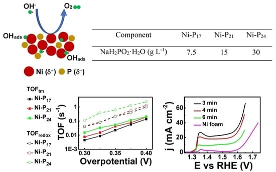
| Component | Ni–P17 | Ni–P21 | Ni–P24 |
|---|---|---|---|
| NaH2PO2·H2O (g L−1) | 7.5 | 15 | 30 |
| Catalyst Material | Electrolyte | Overpotential at 10 mA cm−2 (mV) | Tafel Slope (mV dec−1) | TOFtm (s−1) | TOFredox (s−1) | Electrode | Reference |
|---|---|---|---|---|---|---|---|
| NiP nanoparticles | 1 M KOH | 380 | 106 | GCE | [48] | ||
| NiP nanosheets | 1 M KOH | 230 | 68 | 0.0058 (350 mV) | Carbon fiber | [49] | |
| Ni2P superstructures | 1 M KOH | 200 | 72 | 0.015 (350 mV) | Ni foam | [50] | |
| Ni2P microarrays | 1 M KOH | 305 | 110 | Ni foam | [51] | ||
| Ni2P nanowires | 1 M KOH | 400 | 60 | FTO | [52] | ||
| NiP nanocrystals | 1 M KOH | 260 | 62 | 0.074 (300 mV) | GCE | [53] | |
| NiP nanocatalysts | 1 M KOH | 330 | 92 | GCE | [54] | ||
| NiP films | 1 M KOH | 344 | 49 | Copper foil | [55] | ||
| Ni2P nanoparticles | 1 M KOH | 310 | 71 | 0.05 (400 mV) | Carbon paper | [22] | |
| Ni2P nanoparticles | 1 M KOH | 350 | 72 | GCE | [56] | ||
| NiP spheres | 1 M KOH | 307 | 107 | 0.16 (350 mV) | Carbon paper | [57] | |
| Ni2P nanowires | 1 M KOH | 290 | 47 | 0.012 (300 mV) | GCE | [58] | |
| Ni2P nanosheets | 1 M KOH | N.A. | 78 | Ni foam | [59] | ||
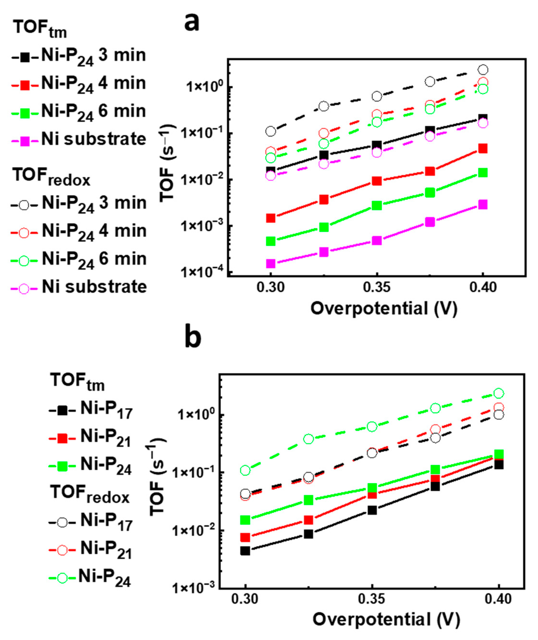
| NiP nanocoatings | 1 M KOH | 388 | 70 | 0.01 (300 mV) 0.05 (350 mV) | 0.11 (300 mV) 0.62 (350 mV) | Ni flat | This work |
| NiP nanocoatings | 1 M KOH | 335 | 71 | Ni foam | This work |
Publisher’s Note: MDPI stays neutral with regard to jurisdictional claims in published maps and institutional affiliations. |
© 2021 by the authors. Licensee MDPI, Basel, Switzerland. This article is an open access article distributed under the terms and conditions of the Creative Commons Attribution (CC BY) license (https://creativecommons.org/licenses/by/4.0/).
Share and Cite
Battiato, S.; Urso, M.; Cosentino, S.; Pellegrino, A.L.; Mirabella, S.; Terrasi, A. Optimization of Oxygen Evolution Reaction with Electroless Deposited Ni–P Catalytic Nanocoating. Nanomaterials 2021, 11, 3010. https://0-doi-org.brum.beds.ac.uk/10.3390/nano11113010
Battiato S, Urso M, Cosentino S, Pellegrino AL, Mirabella S, Terrasi A. Optimization of Oxygen Evolution Reaction with Electroless Deposited Ni–P Catalytic Nanocoating. Nanomaterials. 2021; 11(11):3010. https://0-doi-org.brum.beds.ac.uk/10.3390/nano11113010
Chicago/Turabian StyleBattiato, Sergio, Mario Urso, Salvatore Cosentino, Anna Lucia Pellegrino, Salvo Mirabella, and Antonio Terrasi. 2021. "Optimization of Oxygen Evolution Reaction with Electroless Deposited Ni–P Catalytic Nanocoating" Nanomaterials 11, no. 11: 3010. https://0-doi-org.brum.beds.ac.uk/10.3390/nano11113010