
Crystal Growth and Design of Disk/Filament ZnO-Decorated 1D TiO2 Composite Ceramics for Photoexcited Device Applications

Department of Optoelectronics and Materials Technology, National Taiwan Ocean University, Keelung 20224, Taiwan
*
Author to whom correspondence should be addressed.
Nanomaterials 2021, 11(3), 667; https://0-doi-org.brum.beds.ac.uk/10.3390/nano11030667
Submission received: 2 February 2021
/
Revised: 3 March 2021
/
Accepted: 5 March 2021
/
Published: 8 March 2021
(This article belongs to the Special Issue Nanostructures for Photonics and Optoelectronics)
Abstract
:Disk- and filament-like ZnO crystals were decorated on one-dimensional TiO2 nanostructures (TiO2–ZnO) through various integrated physical and chemical synthesis methods. The morphology of the ZnO crystals on TiO2 varied with the chemical synthesis method used. ZnO nanodisks decorated with TiO2 nanorods (TiO2–ZnO–C) were synthesized using the chemical bath deposition method, and ZnO filament-like crystals decorated with TiO2 nanorods (TiO2–ZnO–H) were synthesized through the hydrothermal method. Compared with the pristine TiO2 nanorods, the as-synthesized TiO2–ZnO composites exhibited enhanced photophysiochemical performance. Furthermore, because of their fast electron transportation and abundant surface active sites, the ZnO nanodisks in the TiO2–ZnO–C composite exhibited a higher photoactivity than those in the TiO2–ZnO–H composite. The morphology and crystal quality of the ZnO decoration layer were manipulated using different synthesis methods to realize disk- or filament-like ZnO-decorated TiO2 composites with various photoactive performance levels.
1. Introduction
TiO2 nanorods, which are one-dimensional (1D) oxides, have wide applicability in various photophysiochemical devices [1,2,3,4]. The crystalline quality, composition, and morphology of TiO2 nanorods influence their efficiencies [5,6]. TiO2 nanorods can be synthesized through various physical and chemical methods. Hydrothermal crystal growth is preferred for synthesizing free-standing TiO2 nanorod arrays because this method enables large-area crystal growth, facile process parameter control, and the use of flexible substrate materials [7,8,9]. ZnO crystals, such as nanosheets or nanoplates, are promising components for photoexcited nanodevices [10,11,12]. Numerous synthesis methods, including chemical vapor deposition [13], evaporation [14], chemical bath deposition [15], and hydrothermal methods [10], have been proposed for fabricating sheet-, plate-, or disk-like ZnO crystal composites. In contrast to other methods, hydrothermal and chemical bath deposition methods can be used for fabricating homogeneous ZnO crystals with a large area distribution over substrates because these methods are simple, have low cost, require a low growth temperature, and provide a high yield.
The nanosheet-decorated 1D nanorod hierarchical structure is used in the fabrication of various photosensitive nanodevices because this composite structure exhibits high light utilization efficiency and a large effective surface area and can facilitate rapid charge transfer and the efficient collection of photogenerated carriers. For example, 1D TiO2-nanosheet Bi2S3 composites exhibit excellent photoelectrochemical performance; this is attributable to the efficient charge transfer ability in the system [16]. Moreover, the WO3–ZnO composite exhibits superior photocatalytic performance, which is associated with efficient charge separation in the system [17]. Furthermore, the photoexcited properties of ZnO nanorod arrays have been substantially improved through the decoration of tin sulfide nanosheets [18]. On the basis of the aforementioned attributes, 2D oxide semiconductors cross-linked on 1D oxide nanorods form a heterogeneous hierarchical structure, which is a promising nanoplatform for improving photoactive performance through efficient charge separation and transfer in the composite system. Notably, band alignment has revealed the presence of a type-II heterojunction between TiO2 and ZnO for various morphologies, such as TiO2 nanorods–ZnO nanorods and TiO2 nanowire–ZnO nanoparticles, which exhibit superior photoactive performance to their constituents [19,20]. However, limited studies have been conducted on the synthesis of TiO2–ZnO branched hierarchical composites, such as 1D TiO2–ZnO sheets (or disks). Furthermore, the related ZnO morphology and crystal-quality-influenced photoactive performance of TiO2–ZnO composites have not been systematically investigated. In this study, TiO2–ZnO composites comprising 1D TiO2 and disk- or filament-like ZnO nanostructures were fabricated by integrating the method assisted by a sputtering-grown ZnO seed layer and various chemical ZnO synthesis methods. The crystal characterization of the ZnO nanostructures on TiO2 nanorods was controlled by varying parameters of chemical bath deposition and hydrothermal crystal growth. The as-synthesized TiO2–ZnO composites exhibited superior photophysiochemical performance to pristine TiO2 nanorods. This result was associated with band matching between ZnO and TiO2 together with the rationally designed dimensionality-dependent heterojunctions for promoting photoactivity. Tuning the morphology and crystal quality of as-synthesized TiO2–ZnO composites systems through suitable chemical synthesis methods with controllable sputtering ZnO seed layer quality is a promising approach for fabricating 1D TiO2–ZnO disk (or filament) composites. Such composites are used for fabricating desirable photoactive devices.
2. Experiments
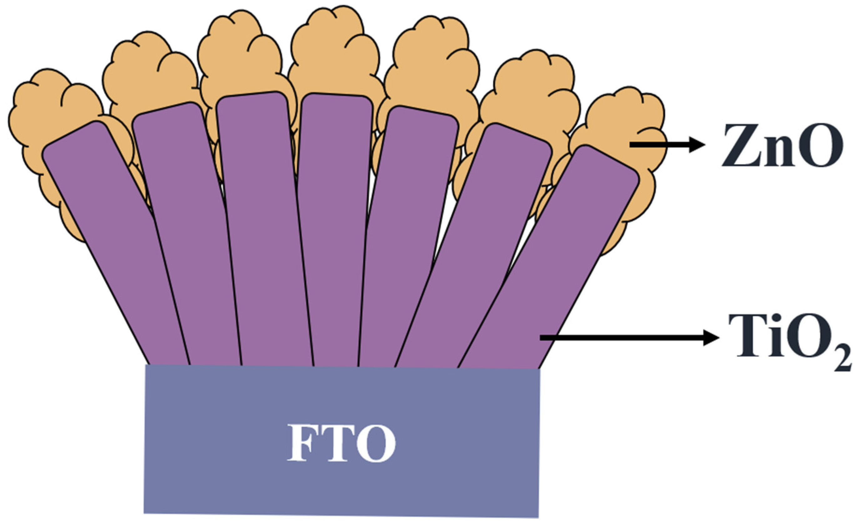
TiO2 nanorod arrays were grown on clean fluorine-doped tin oxide (FTO) substrates via a hydrothermal growth method. The detailed hydrothermal growth parameters of the TiO2 nanorod arrays have been described elsewhere [4]. For growing chemical-route-derived ZnO crystallites on the TiO2 nanorod template to form TiO2–ZnO composite structures, the ZnO seed layer was deposited onto the TiO2 nanorod template by radio-frequency sputtering (named TiO2–ZnO–S). A ZnO ceramic disc (99.999% Pure, 3.0 inch diameter) was used as the target for sputtering the ZnO seed layer. Herein, the argon and oxygen gas flow rates were set at 20 and 5 sccm, respectively. The ZnO seed layer deposition was performed at 90 W for 1 h at room temperature. In this study, two sets of TiO2–ZnO composite structures were prepared. The solution of 0.3 g of Zn(NO3)2 6H2O, 0.14 g of hexamethylenetetramine (HMT, C6H12N4), and 0.028 g of sodium citrate (Na3C6H5O7) was mixed with 100 mL of DI water and stirred for 10 min. For chemical bath deposition (CBD), the prepared solution was further transferred to CBD apparatus and then kept in a water bath at a temperature of 90 °C for 4 h. The as-synthesized TiO2–ZnO composite structure via this approach was named TiO2–ZnO–C. On the other hand, the same reactant solution was transferred into 20 mL capacity Teflon enclosed with a stainless steel bottle for hydrothermal crystal growth. The reaction was conducted at 90 °C for 4 h. The as-synthesized product herein was named TiO2–ZnO–H. Figure 1 shows the schematic configuration of the as-synthesized composites in this study.
The surface and microstructures of the samples were investigated by scanning electron microscopy (SEM, Hitachi S-4800, Tokyo, Japan) and transmission electron microscopy (HRTEM; JEOL JEM-2100F, Tokyo, Japan). The crystalline phases of the samples were characterized by X-ray diffraction (XRD; D2 PHASER, Karlsruhe, Germany) using Cu Kα radiation. The absorption spectra of the samples were obtained using a diffuse-reflectance mode via an ultraviolet–visible spectrophotometer (UV–vis; Jasco V750, Tokyo, Japan). The photoelectrochemical (PEC) properties of the samples were obtained by an AutoLab electrochemical workstation (BioLogic SP150, Seyssinet-Pariset, France). Electrochemical impedance spectra (EIS) were measured on the same workstation with a saturated Ag/AgCl electrode. The sample was used as the working electrode. The counter electrode is Pt wire. The electrolyte contains 0.5 M Na2SO4. The photocatalytic activity of the samples was evaluated by the degradation of 10 mL of aqueous solution of methyl orange (MO; 5 × 10⁻⁵ M) dye with a 100 W Xe lamp as the light source. The photocatalyst sample size is 10 mm × 10 mm.
3. Results and Discussion
Figure 2a,b illustrates SEM micrographs of hydrothermally derived TiO2 nanorod templates. The TiO2 nanorods exhibited a square facet morphology, which is the expected growth habit for the tetragonal crystal structure. The TiO2 nanorod template exhibited smooth side facets. Furthermore, the cross-sectional view of the TiO2 nanorod template demonstrates a well-aligned feature on the fluorine-doped tin oxide substrate. The free-standing TiO2 nanorods had lengths and diameters of approximately 0.8–1.2 μm and 50–90 nm, respectively. Figure 2c,d illustrates the morphology of the TiO2 nanorod template decorated with CBD-derived ZnO nanodisks (TiO2–ZnO–C). The ZnO nanodisks were grown in a staggered manner on the TiO2 nanorods, which resulted in a branched morphology. The diameter of the ZnO nanodisks varied from 100 to 250 nm, with the thickness ranging from 30 to 50 nm. Notably, the ZnO nanodisks had a hexagonal shape corresponding to the wurtzite ZnO hexagonal crystallographic structure. The formation of hexagonal ZnO nanodisks was attributed to growth suppression on the (002) facet, which leads to the formation of six-fold symmetric hexagonal nanoplates [21]. The aggregation of numerous interlocked thin disk structures provides abundant spaces between primary ZnO disks filled with TiO2 nanorods, which may facilitate sufficient surface area exposure in the reaction environment. Figure 2e,f displays SEM micrographs of the TiO2 nanorod template decorated with hydrothermally derived ZnO filaments (TiO2–ZnO–H). Most ZnO aggregates were formed on the top regions of the TiO2 nanorods, and ZnO filaments extended outward to connect with each other. The thin ZnO filaments covered the TiO2 nanorod template like a net. SEM revealed that the ZnO crystals obtained through the two-step hydrothermal process and the CBD-derived ZnO crystals were distributed in the TiO2 top region and interweaved with neighboring segments. The results revealed that the ZnO nanostructures synthesized through various chemical routes considerably affected the morphologies of the TiO2–ZnO heterogeneous composites.
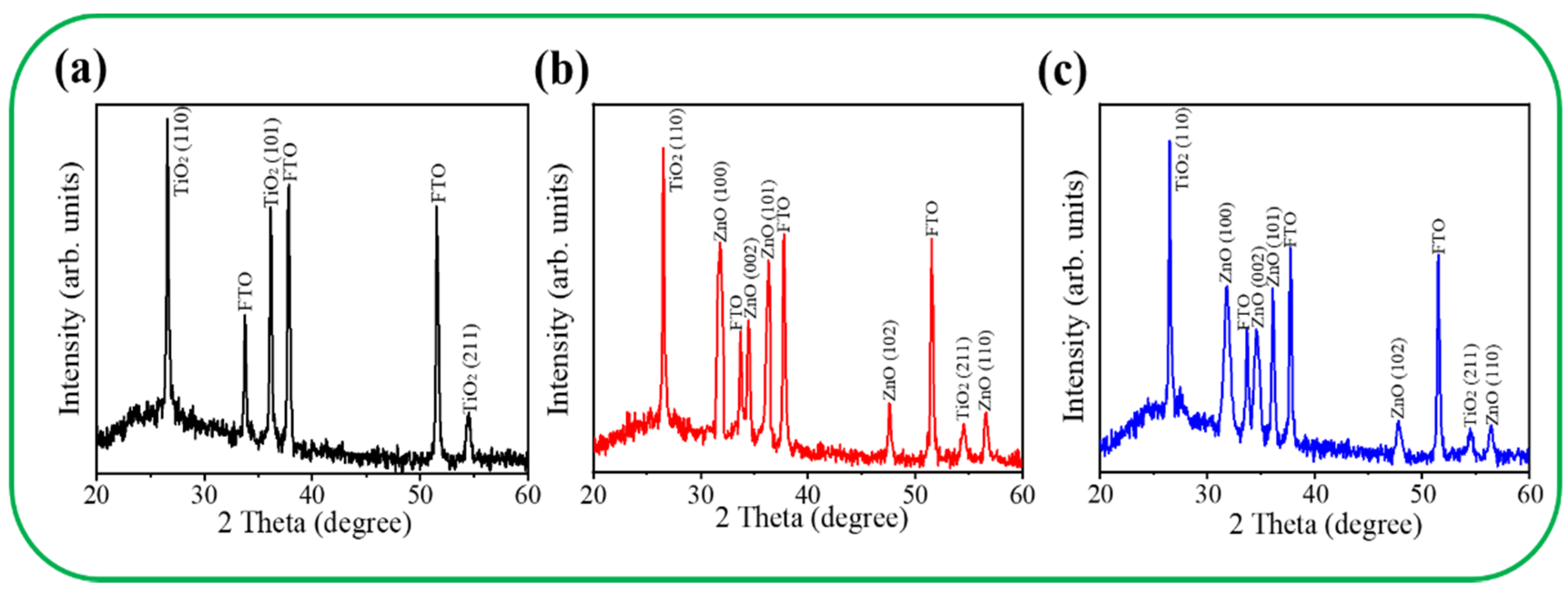
The reference XRD pattern of the pristine TiO2 nanorod template is shown in Figure 3a. In addition to FTO Bragg reflections, three clear diffraction peaks located at approximately 27.45°, 36.08°, and 54.32° correspond to the TiO2 crystallographic planes of (110), (101), and (211) (JCPDS No. 00-021-1276), respectively. Figure 3b,c presents the XRD patterns of the TiO2–ZnO–C and TiO2–ZnO–H composites, respectively. From the XRD patterns, several ZnO diffraction peaks were distinguished according to JCPDS No. 00-036-1451. Notably, the XRD results reveal (100) and (101) nonpolar planes dominated the crystallographic feature of the ZnO crystals decorated on the TiO2 nanorod templates. A similar nonpolar crystallographic-plane-dominated ZnO crystal feature has been reported in chemical-route-derived 2D ZnO sheets [10]. It should be mentioned that the positively Zn2+-terminated (002) facets and negatively O2−-terminated {002} polar surfaces of wurtzite ZnO are more reactive [15], and the fastest growth rate along the c-axis due to the higher surface energy of {002} planes is frequently observed in chemical-route-derived ZnO crystals [22]. In this study, the sodium citrate was introduced into the chemical solution process to serve as a structure-directing agent, and complexation between Zn2+ ions and citrate can ligand to suppress the ZnO crystal growth along the [001] direction [23]. The disclosed crystallographic feature of the chemical-route-derived ZnO crystals is consistent with the morphology observation from the SEM images. Comparatively, the ZnO Bragg reflections from the TiO2–ZnO–C are higher in intensity and narrower in peak width than those of the TiO2–ZnO–H, demonstrating a higher crystalline quality of the 2D ZnO crystals in the TiO2–ZnO–C.
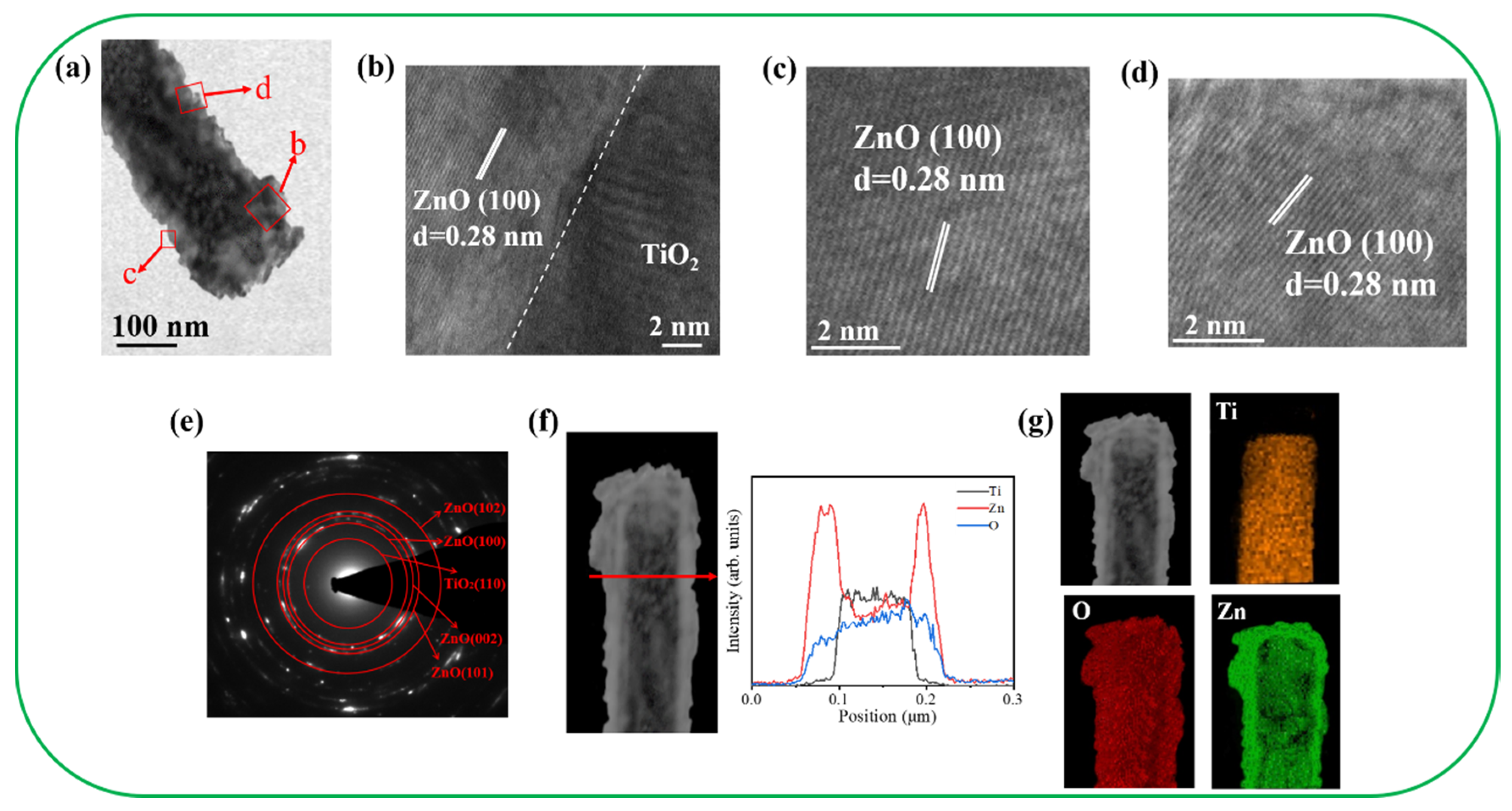
Figure 4a illustrates the morphology of the TiO2–ZnO–C composite rod. The diameter of the rod was approximately 120 nm. The ZnO crystals displayed in Figure 4a were grown on a TiO2 surface in a staggered manner. The decoration of the ZnO crystals on TiO2 resulted in the generation of irregular surface edges on the composite. The high-resolution (HR) TEM images (Figure 4b–d) of the local regions of the composite rod display the interface of the TiO2/ZnO and ZnO regions. A sharp interface was observed between TiO2 and ZnO. The remarkable lattice fringes with ordered arrangements and an interplanar spacing of 0.28 nm corresponded to the hexagonal ZnO(100) plane. The HRTEM results indicated that the TiO2–ZnO–C composite nanostructure exhibited a highly crystalline structure. Figure 4e illustrates the selected area electron diffraction (SAED) pattern of several TiO2–ZnO–C composite rods. The distinct spots arranged in concentric rings could be attributed to the hexagonal ZnO (100), (002), (101), and (102) planes and the rutile TiO2 (110) plane. The SAED results agreed with the X-ray diffraction results, which indicated that the crystalline TiO2–ZnO–C composite rods were formed through the proposed combined hydrothermal–chemical bath methodology. Figure 4f illustrates the spatial distribution of the Ti, Zn, and O elements across the TiO2–ZnO–C composite rod. This distribution was obtained using the TEM–energy-dispersive spectroscopy (EDS) line-scan profiling method. The variation of elemental intensity profiles indicated that Ti was mainly confined within the inner area of the composite rods and that Zn was distributed around the TiO2 nanorod template. Figure 4g illustrates the high-angle dark-field TEM image and the corresponding EDS elemental mapping images. The results revealed that Ti was perfectly filled in the inner area of the composite structure. Furthermore, the outer region of the composite structure clearly revealed the Zn signal. O was homogeneously distributed over the composite structure. The compositional analysis results revealed rational Zn, Ti, and O distribution in the TiO2–ZnO–C composite structure.
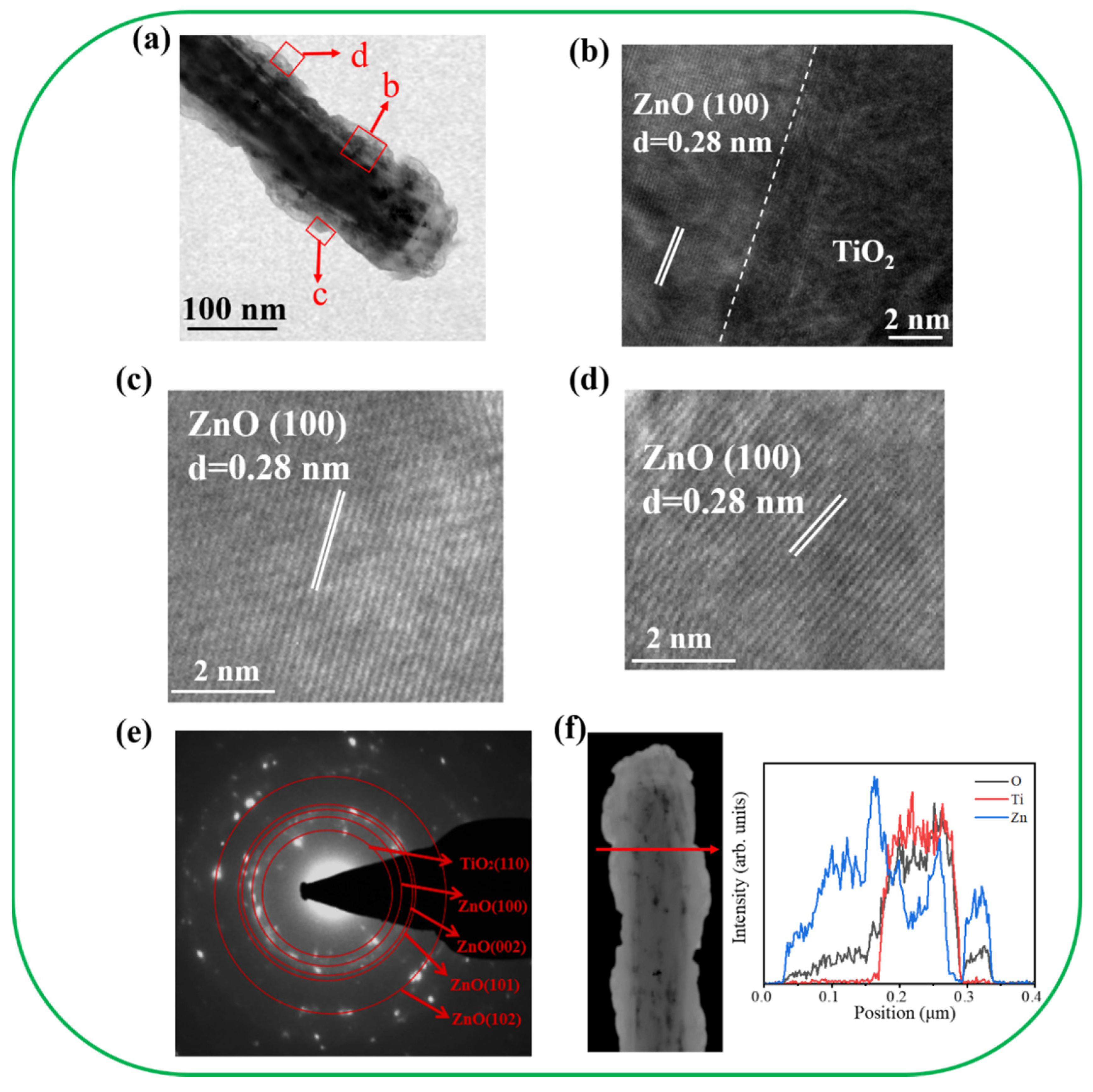
Figure 5a depicts the morphology of the TiO2–ZnO–H composite rod. Feather-like ZnO crystals were visibly grown on the TiO2 nanorod template, indicating the formation of a composite structure. Figure 5b–d presents the HRTEM images of the local regions of TiO2/ZnO and ZnO of the TiO2–ZnO–H. The ordered fringe spacing of 0.28 nm matches well with the interplanar spacing of the ZnO (100) plane, revealing the crystalline feature of the decorated ZnO. Figure 5e displays the SAED pattern of several TiO2–ZnO–H composite rods. Numerous visible spots arranged in centric patterns were observed. The concentric rings were ascribed to diffractions from the rutile TiO2 (110) plane and the hexagonal ZnO (100), (002), (101), and (102) planes. The SAED analysis reveals the crystalline nature of the TiO2–ZnO–H. Figure 5f exhibits the EDS line-scan profiling spatial distribution of the Ti, Zn, and O across the TiO2–ZnO–H composite rod. The results herein indicate the two steps hydrothermal growth process is feasible for preparing a heterogeneous structure of TiO2/ZnO.
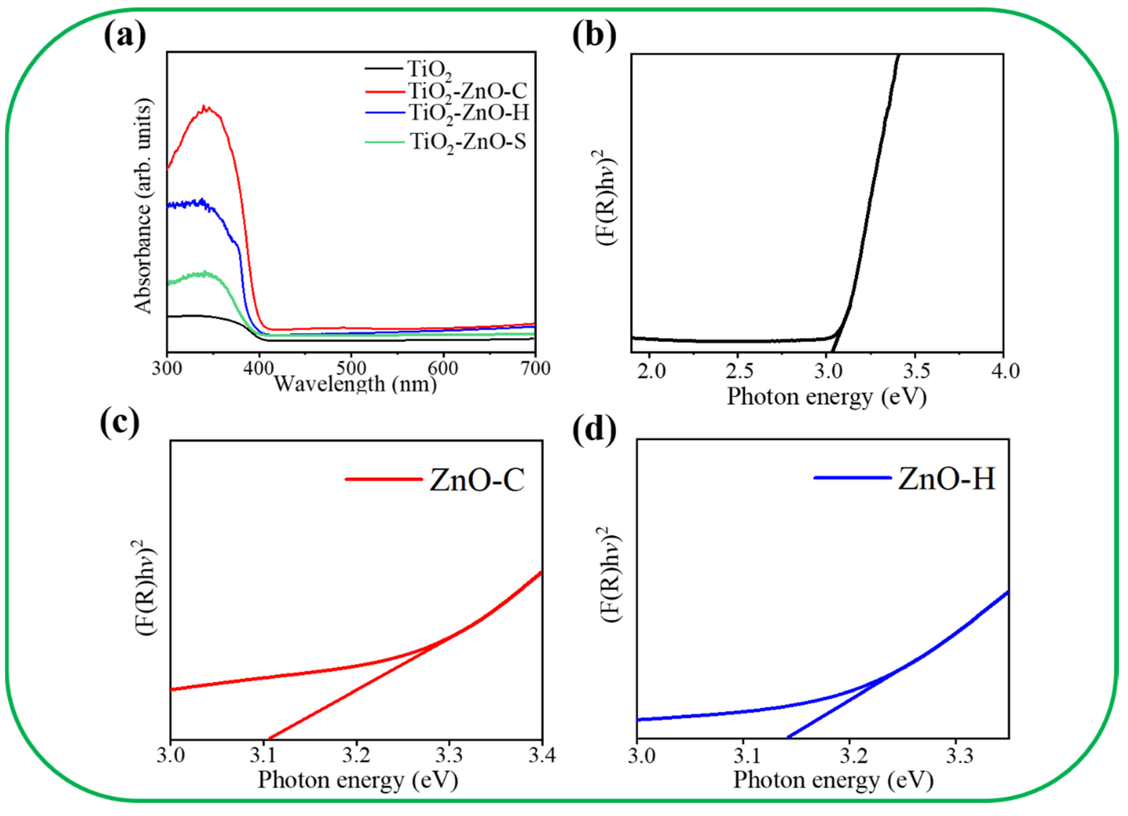
Figure 6a shows the absorption spectra of various samples. A strong absorption edge at approximately 410 nm appears in the absorption spectrum of the TiO2 nanorod template. In Figure 6b, the bandgap energy of the TiO2 template is evaluated to be approximately 3.03 eV. After the ZnO nanostructures were grown on the surfaces of the TiO2 nanorod template via CBD or hydrothermal growth, the absorption edge of the TiO2–ZnO composites shows a slightly red shift in comparison with that of the pristine TiO2 nanorod template. In contrast, the pristine TiO2 nanorod template demonstrated a lower light-harvesting efficiency in comparison with the TiO2–ZnO composite structures from the absorption analysis. This is in agreement with recent work on TiO2 nanorod arrays/ZnO nanosheets heterostructured photoanodes, which also demonstrates that the TiO2–ZnO composite shows excellent light absorption ability than the pristine TiO2 nanorod [24]. Furthermore, TiO2–ZnO–C displays the highest light-harvesting ability among various samples. Figure 6c,d presents the bandgap energy evaluation of pristine ZnO crystals synthesized via CBD and hydrothermal growth, respectively. The detailed band gap energy evaluation process has been described elsewhere [25]. Notably, the ZnO crystals synthesized via the CBD route demonstrate a lower bandgap energy of 3.11 eV than that of the hydrothermally derived ZnO crystals. The different crystal qualities and features of the ZnO crystals synthesized via various chemical routes might result in the observed bandgap energy difference herein. The observations herein are supported by the work on the ZnO nanosheets/nanodisks synthesized by using ethyl cellulose and cetrimonium bromide as the capping and structure-directing agents. In that work, the as-synthesized ZnO nanodisks have a smaller bandgap energy in contrast to ZnO nanosheets, and this is attributed to the crystalline quality difference between the ZnO nanodisk and nanosheet [26].
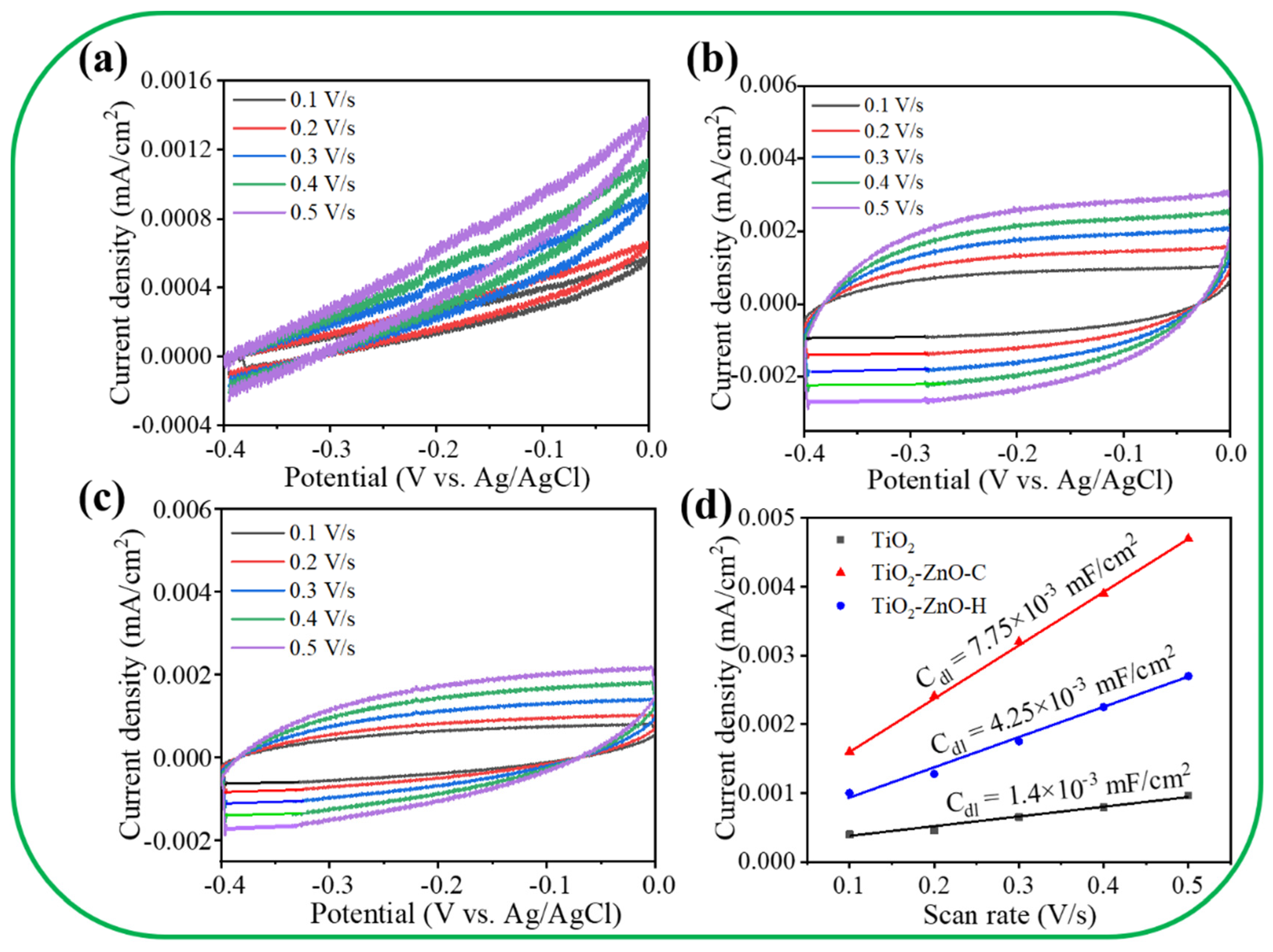
Figure 7a–c presents cyclic voltammogram (CV) curves at various scan rates for various samples. Figure 7d displays the electrochemical double-layer capacitance (Cdl) values of various photoelectrodes calculated from the slope of the corresponding current density versus scan rate (v) curves according to the equation: capacitive current ∆j = v Cdl for a middle potential of −0.2 V [27]. For comparison, the result of the pristine TiO2 was included. Furthermore, Cdl is positively proportional to the electrochemical surface area (ECSA). The ECSA size of the as-fabricated photoanodes was estimated from their Cdl values [28]. The Cdl values of the TiO2 and TiO2–ZnO–H photoelectrodes were 1.4 × 10⁻³ and 4.25 × 10⁻³ mF/cm2, respectively. Remarkably, the Cdl value of the TiO2–ZnO–C electrode was 7.75 × 10⁻³ mF/cm2, which is approximately 1.8 and 5.5 times higher than the Cdl values of TiO2–ZnO–H and TiO2, respectively. A larger ECSA provided more active sites for the interface reaction between the as-fabricated photoelectrodes and the electrolyte. The excellent charge transfer behavior and high surface area were attributed to the large ECSA of the nanomaterials. The ZnO/V2O5 heterogeneous structure had a higher ECSA than pristine ZnO did; thus, the PEC performance of ZnO/V2O5 was superior to that of ZnO [29]. The high ECSA of TiO2–ZnO–C exposed a high number of surface active sites, which enabled the maintenance of a sufficient electrochemical reaction between the TiO2–ZnO–C nanostructures and electrolyte ions in this study. This result revealed that the morphology and crystal quality of the decorated ZnO crystals on the TiO2 nanorod template influenced the Cdl values and ECSA, which in turn affected the photoactive performance.
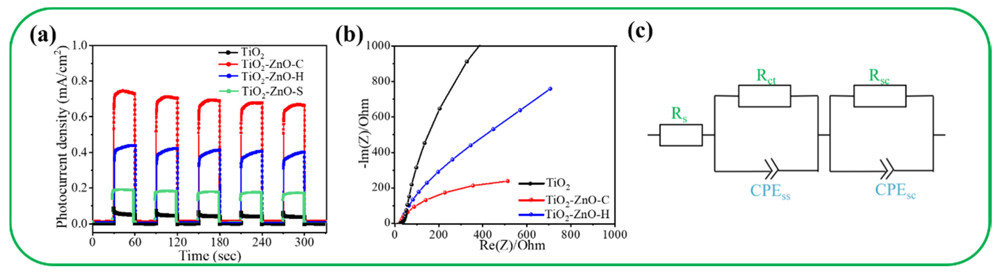
Figure 8a displays the transient photocurrent responses of various samples under chopping light irradiation at 1.1 V. All the nanorod-based photoelectrodes demonstrated a visible photoresponse ability. Figure 8a indicates that the photocurrent density of the samples was stable, and the samples exhibited excellent reproducibility. The saturated photocurrent densities of the pristine TiO2 and TiO2–ZnO–S photoelectrodes were approximately 0.06 and 0.2 mA/cm2. The TiO2–ZnO–C photoelectrode exhibited the highest saturated photocurrent density of 0.75 mA/cm2, which was approximately 12 times that of TiO2. The TiO2–ZnO–H photoelectrode exhibited a saturated photocurrent density of approximately 0.42 mA/cm2, which was approximately seven times that of pristine TiO2. Notably, the ZnO seed layer coated TiO2 showed markedly lower photoresponse performance than the composites formed after the further decoration of ZnO crystals via chemical solution routes. The TiO2–ZnO-C composite photoelectrode exhibited superior photoresponse performance to the other photoelectrodes. The aforementioned result is similar to that obtained in a previous study for a WO3 nanosheet-decorated CdS nanorod composite, which revealed substantially improved PEC performance to pristine CdS because of the improved photogenerated charge separation ability in the heterogeneous system [30]. Figure 8b displays the Nyquist plots of the TiO2, TiO2–ZnO–C, and TiO2–ZnO–H photoelectrodes under irradiation. The TiO2–ZnO–C photoelectrode had the smallest arc radius among all the photoelectrodes, which indicated that the TiO2–ZnO–C photoelectrode had the lowest charge transfer resistance [31]. Figure 8c presents the possible equivalent circuit for the TiO2–ZnO composite photoelectrodes in the Nyquist plot. In Figure 8c, Rsc is the solution resistance, and Rct is the surface state resistance that is related to the charge transfer from the valence band or conduction band to the semiconductor electrode surface [32]. The parameters CPEss and CPEsc are constant-phase elements for the electrolyte–electrode interface and electrode surface, respectively [33]. The Rct values of various composite photoelectrodes were evaluated by fitting the Nyquist plot under the proposed equivalent circuit mode. The TiO2-ZnO-C and TiO2-ZnO-H photoelectrodes exhibited Rct values of 352 and 559 Ω, respectively. Notably, the Rct of the TiO2 photoelectrode is high and reaches 3507 Ω. The results revealed that the ZnO nanodisks in TiO2–ZnO–C provided superior photoactive performance to those in TiO2–ZnO–H.
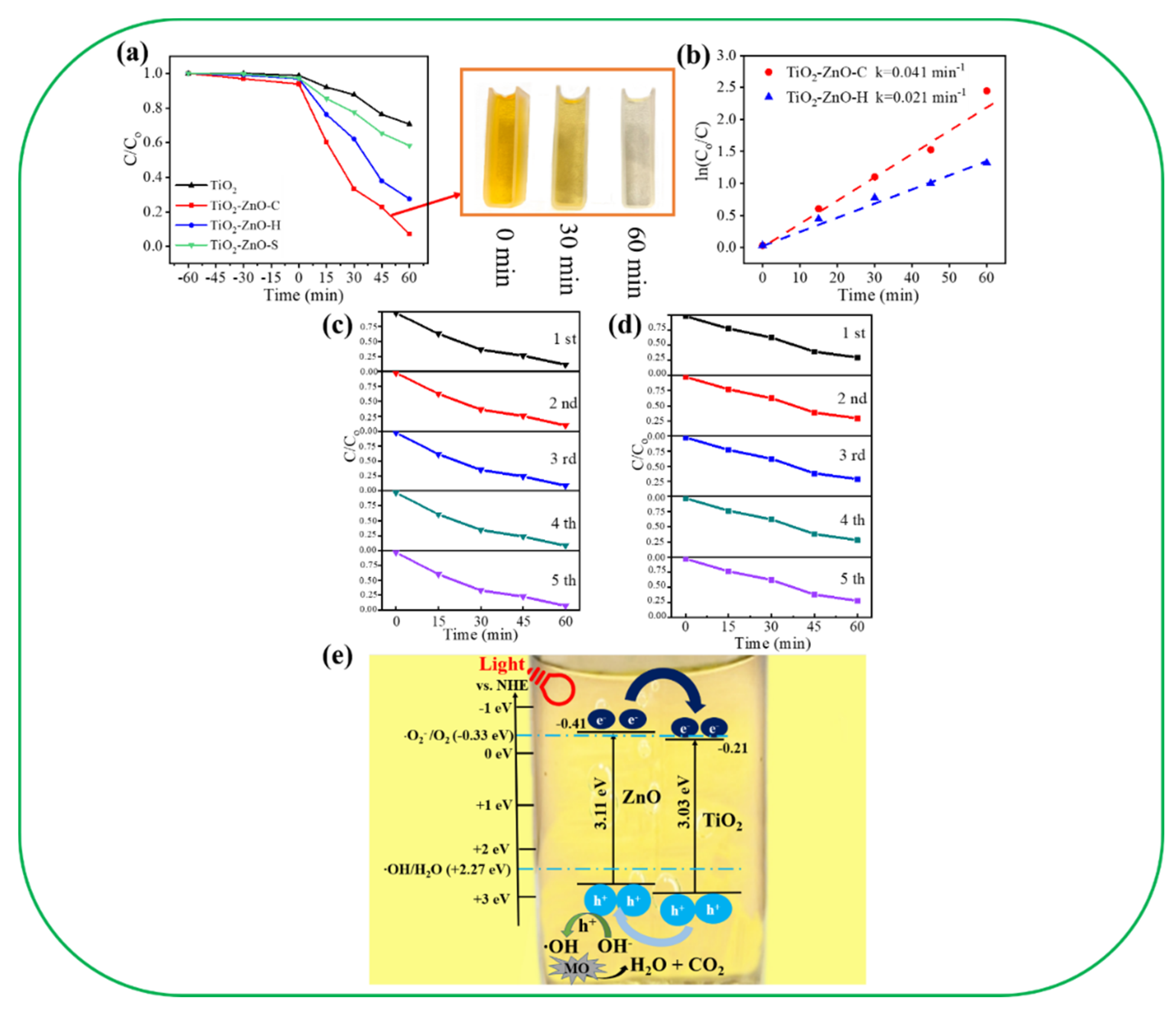
Figure 9a displays the relative concentration (C/Co) of the MO solution vs. irradiation time plots for various photocatalysts. Prior to irradiation, the adsorption/desorption equilibrium of the MO solution with various photocatalysts in the dark condition was established. In the presence of the pristine TiO2 and TiO2–ZnO–S photocatalysts, the degradation of the MO solution only reached 29.4% and 42.1% after 60 min of light irradiation. In contrast, the photodegradation of the MO solution is significantly increased to 92.4% with the TiO2–ZnO–C photocatalyst, whereas the TiO2-ZnO-H photocatalyst exhibited moderate photocatalytic activity and photodegraded the MO solution at 72.4%. The inset in Figure 9a also presents the discoloration of MO solution containing TiO2–ZnO–C at various irradiation durations. Figure 9b indicates that the TiO2–ZnO–C photocatalyst had the highest rate constant (k = 0.041 min−1), which was approximately 1.96 times that of TiO2–ZnO–H (k = 0.021 min−1) according to the pseudo-first-order kinetics at low initial concentrations. Furthermore, cycling experiments were performed to evaluate the stability and reusability of the TiO2–ZnO–C and TiO2–ZnO–H photocatalysts (Figure 9c,d, respectively). After five reuse tests, the TiO2–ZnO–C and TiO2–ZnO–H photoelectrodes exhibited high stability and reusability. Approximately 88.9% and 70.4% photodegradation of the MO solution was observed for the TiO2–ZnO–C and TiO2–ZnO–H photoelectrodes, respectively. This result indicates that the synthesized TiO2–ZnO–C and TiO2–ZnO–H composite photocatalysts have excellent stability and reusability and are promising for photocatalysis applications. The possible photodegradation mechanism of the TiO2–ZnO composite photocatalyst is illustrated in Figure 9e. In the TiO2–ZnO composite system, the conduction band of TiO2 was located at −0.21 eV and that of ZnO was located at approximately −0.41 eV [19]. Figure 9e indicates that the constructed TiO2/ZnO system exhibited a staggered type-II band alignment configuration, which is similar to that of the TiO2 nanowire/ZnO nanoparticle system [20]. Interband transitions in ZnO and TiO2 were speculated to have occurred during light irradiation. Because of the various positions of the valence and conduction bands of TiO2 and ZnO, the recombination of the photoinduced carriers in the composite system was suppressed according to the following reaction: TiO2–ZnO composite nanorods + hv (charge separation)→TiO2 nanorod template (e−) + ZnO coverage layer (h+). Moreover, the root of the TiO2 template without the coverage of ZnO will also produce photoexcited e− and h+. Notably, the oxidation(⋅O2−/O2) and reduction (⋅OH/H2O) potentials were −0.33 and +2.27 eV (vs. NHE), respectively [34], which indicated that the electrons that accumulated on the TiO2 conduction band in the composite system or the pristine TiO2 section were not involved in the photodegradation process of the MO dye through the formation of ⋅O2− radicals. By contrast, the highly oxidative holes on the ZnO valence band were involved in the reactions with bounded hydroxide species to produce ⋅OH radicals according to the reaction OH− + h+→ ⋅OH. The ⋅OH radicals further reacted with MO molecules to form CO2 and H2O. Thus, the h+ and ⋅OH radicals played a crucial role in photodegrading the adsorbed MO molecules, which led to the formation of a strong photocatalyst for the TiO2–ZnO heterojunction. Comparatively, from the PEC and photodegradation results, the free h+ involved in photocatalytic reaction contributed from the pristine TiO2 section of the composite system is relatively low. The heterogeneous effect on the charge separation efficiency is the predominant role of the improved photodegradation performance of the TiO2–ZnO composite. Notably, TiO2–ZnO–C demonstrated a higher photodegradation efficiency for MO dyes than TiO2–ZnO–H did. This result was attributed to the several advantages of the decorated ZnO nanodisks. The ZnO nanodisks exhibited higher crystalline quality than the ZnO filaments did. Moreover, the ZnO nanodisks exhibited a larger surface area than the ZnO filaments did, which resulted in increases in the dye adsorption, sunlight utilization capability, and photocatalytic activity of the exposed facets in TiO2–ZnO–C.
4. Conclusions
In this study, 1D TiO2 and 2D ZnO nanocomposites were fabricated using the sputtering-grown ZnO-seed-layer-assisted method and various chemical ZnO synthesis methods. The chemical synthesis method affects the morphology and crystal quality of the 2D ZnO nanostructures on TiO2 nanorod templates. The results for PEC, EIS, ECSA, and the hydrophilic property revealed that the ZnO nanodisks caused the TiO2–ZnO composite to have higher photoactivity than the ZnO filaments did. The TiO2–ZnO system exhibited a type-II band alignment configuration, which explains why the TiO2–ZnO composite had a higher photoactivity than pristine TiO2. The experimental results indicated that the TiO2–ZnO–C composite structure had superior photophysiochemical properties to the TiO2–ZnO–H structure. This result was associated with the superior surface area and crystalline quality of the 2D ZnO crystals in TiO2–ZnO–C.
Author Contributions
Methodology, W.-C.Z.; formal analysis, W.-C.Z.; Writing—original draft preparation, Y.-C.L.; supervision, Y.-C.L. Both authors have read and agreed to the published version of the manuscript.
Funding
This research was funded by the Ministry of Science and Technology of Taiwan. Grant No. MOST 108-2221-E-019-034-MY3.
Conflicts of Interest
The authors declare no conflict of interest.
References
- Jiang, Y.; Guo, S.; Hao, R.; Luan, Y.; Huang, Y.; Wu, F.; Tian, C.; Jiang, B. A hybridized heterojunction structure between TiO2 nanorods and exfoliated graphitic carbon-nitride sheets for hydrogen evolution under visible light. CrystEngComm 2016, 18, 6875–6880. [Google Scholar] [CrossRef]
- Gai, L.; Duan, X.; Jiang, H.; Mei, Q.; Zhou, G.; Tian, Y.; Liu, H. One-pot synthesis of nitrogen-doped TiO2 nanorods with anatase/brookite structures and enhanced photocatalytic activity. CrystEngComm 2012, 14, 7662–7671. [Google Scholar] [CrossRef]
- Wu, Z.; Dong, F.; Zhao, W.; Wang, H.; Liu, Y.; Guan, B. The fabrication and characterization of novel carbon doped TiO2 nanotubes, nanowires and nanorods with high visible light photocatalytic activity. Nanotechnology 2009, 20, 235701. [Google Scholar] [CrossRef] [PubMed]
- Liang, Y.-C.; Liu, Y.-C. Design of Nanoscaled Surface Morphology of TiO2–Ag2O Composite Nanorods through Sputtering Decoration Process and Their Low-Concentration NO2 Gas-Sensing Behaviors. Nanomaterials 2019, 9, 1150. [Google Scholar] [CrossRef] [PubMed] [Green Version]
- Yin, Z.; Shao, J.; Tang, W.; Sheng, W.; Sun, D.; Xiao, Y.; Cao, S. Design and synthesis of ‘single-crystal-like’ C-doped TiO2 nanorods for high-performance supercapacitors. Nanotechnology 2020, 31, 275401. [Google Scholar] [CrossRef] [PubMed]
- Peng, W.; Yanagida, M.; Han, L.; Ahmed, A.S. Controlled fabrication of TiO2 rutile nanorod/anatase nanoparticle composite photoanodes for dye-sensitized solar cell application. Nanotechnology 2011, 22, 275709. [Google Scholar] [CrossRef]
- Liang, Y.-C.; Liu, Y.-C. Microstructures and Photodegradation Performance toward Methylene Orange of Sputtering-Assisted Decoration of ZnFe2O4 Crystallites onto TiO2 Nanorods. Nanomaterials 2019, 9, 205. [Google Scholar] [CrossRef] [PubMed] [Green Version]
- Wang, S.; Xu, J.; Ding, H.; Pan, S.; Zhang, Y.; Li, G. Facile synthesis of nitrogen self-doped rutile TiO2 nanorods. CrystEngComm 2012, 14, 7672–7679. [Google Scholar] [CrossRef]
- Huyen, T.; Chi, T.; Dung, N.; Kosslick, H.; Liem, N. Enhanced photocatalytic activity of {110}-faceted TiO2 rutile nanorods in the photodegradation of hazardous pharmaceuticals. Nanomaterials 2018, 8, 276. [Google Scholar] [CrossRef] [Green Version]
- Liang, Y.-C.; Hung, C.-S.; Zhao, W.-C. Thermal Annealing Induced Controllable Porosity and Photoactive Performance of 2D ZnO Sheets. Nanomaterials 2020, 10, 1352. [Google Scholar] [CrossRef]
- Hua, G.; Zhang, Y.; Ye, C.; Wang, M.; Zhang, L. Controllable growth of ZnO nanoarrays in aqueous solution and their optical properties. Nanotechnology 2017, 18, 145605. [Google Scholar] [CrossRef]
- Hussain, T.; Kaewmaraya, T.; Khan, M.; Chakraborty, S.; Islam, M.S.; Amornkitbamrung, V.; Ahuja, R. Improved sensing characteristics of methane over ZnO nano sheets upon implanting defects and foreign atoms substitution. Nanotechnology 2017, 28, 415502. [Google Scholar] [CrossRef] [Green Version]
- Chen, S.; Liu, Y.; Shao, C.L.; Xu, C.S.; Liu, Y.X.; Wang, L.; Liu, B.B.; Zou, G.T. Pressure-dependent photoluminescence of ZnO nanosheets. J. Appl. Phys. 2005, 98, 106106. [Google Scholar] [CrossRef]
- Umar, A.; Hahn, Y.B. ZnO nanosheet networks and hexagonal nanodiscs grown on silicon substrate: Growth mechanism and structural and optical properties. Nanotechnology 2006, 17, 2174–2180. [Google Scholar] [CrossRef]
- Cao, B.; Cai, W.; Li, Y.; Sun, F.; Zhang, L. Ultraviolet-light-emitting ZnO nanosheets prepared by a chemical bath deposition method. Nanotechnology 2005, 16, 1734–1738. [Google Scholar] [CrossRef]
- Han, M.; Jia, J. 3D Bi2S3/TiO2 cross-linked heterostructure: An efficient strategy to improve charge transport and separation for high photoelectrochemical performance. J. Power Sources 2016, 329, 23–30. [Google Scholar] [CrossRef]
- Zheng, F.; Lu, H.; Guo, M.; Zhang, M.; Zhen, Q. Hydrothermal preparation of WO3 nanorod array and ZnO nanosheet array composite structures on FTO substrates with enhanced photocatalytic properties. J. Mater. Chem. C 2015, 3, 7612–7620. [Google Scholar] [CrossRef]
- Liang, Y.-C.; Lung, T.-W.; Xu, N.-C. Photoexcited Properties of Tin Sulfide Nanosheet-Decorated ZnO Nanorod Heterostructures. Nanoscale Res. Lett. 2017, 12, 258. [Google Scholar] [CrossRef] [Green Version]
- Liang, Y.-C.; Zhao, W.-C. Morphology-dependent photocatalytic and gas-sensing functions of three-dimensional TiO2–ZnO nanoarchitectures. CrystEngComm 2020, 22, 7575–7589. [Google Scholar] [CrossRef]
- Sun, C.; Xu, Q.; Xie, Y.; Ling, Y.; Hou, Y. Designed synthesis of anatase–TiO2 (B) biphase nanowire/ZnO nanoparticle heterojunction for enhanced photocatalysis. J. Mater. Chem. A 2018, 6, 8289–8298. [Google Scholar] [CrossRef]
- Wang, M.; Hahn, S.H.; Kim, J.S.; Chung, J.S.; Kim, E.J.; Koo, K.-K. Solvent-controlled crystallization of zinc oxide nano(micro)disks. J. Cryst. Growth 2008, 310, 1213–1219. [Google Scholar] [CrossRef]
- Ghoshal, T.; Kar, S.; Chaudhuri, S. Synthesis and optical properties of nanometer to micrometer wide hexagonal cones and columns of ZnO. J. Cryst. Growth 2006, 293, 438–446. [Google Scholar] [CrossRef]
- Liang, J.; Liu, J.; Xie, Q.; Bai, S.; Yu, W.; Qian, Y. Hydrothermal Growth and Optical Properties of Doughnut-Shaped ZnO Microparticles. J. Phys. Chem. B 2015, 109, 9463–9467. [Google Scholar] [CrossRef] [PubMed]
- Zhang, Y.; Zhong, X.; Zhang, D.; Duan, W.; Li, X.; Zheng, S.; Wang, J. TiO2 nanorod arrays/ZnO nanosheets heterostructured photoanode for quantum-dot-sensitized solar cells. Sol. Energy 2018, 166, 371–378. [Google Scholar] [CrossRef]
- Liang, Y.C.; Lung, T.W. Growth of hydrothermally derived CdS-based nanostructures with various crystal features and photoactivated properties. Nanoscale Res. Lett. 2016, 11, 264. [Google Scholar] [CrossRef] [Green Version]
- Chetia, T.R.; Ansari, M.S.; Qureshi, M. Ethyl cellulose and cetrimonium bromide assisted synthesis of mesoporous, hexagon shaped ZnO nanodisks with exposed ±{0001} polar facets for enhanced photovoltaic performance in quantum dot sensitized solar cells. ACS Appl. Mater. Interfaces 2015, 7, 13266–13279. [Google Scholar] [CrossRef]
- McCrory, C.C.L.; Jung, S.; Ferrer, I.M.; Chatman, S.M.; Peters, J.C.; Jaramillo, T.F. Benchmarking Hydrogen Evolving Reaction and Oxygen Evolving Reaction Electrocatalysts for Solar Water Splitting Devices. J. Am. Chem. Soc. 2015, 137, 4347–4357. [Google Scholar] [CrossRef] [Green Version]
- Hu, H.; Guan, B.; Xia, B.; Lou, X.W.D. Designed Formation of Co3O4/NiCo2O4 Double-Shelled Nanocages with Enhanced Pseudocapacitive and Electrocatalytic Properties. J. Am. Chem. Soc. 2015, 137, 5590–5595. [Google Scholar] [CrossRef]
- Hou, T.-F.; Johar, M.A.; Boppella, R.; Hassan, M.A.; Patil, S.J.; Ryu, S.-W.; Lee, D.-W. Vertically aligned one-dimensional ZnO/V2O5 core–shell hetero-nanostructure for photoelectrochemical water splitting. J. Energy Chem. 2020, 49, 262–274. [Google Scholar] [CrossRef]
- Wang, Z.; Yang, G.; Tan, C.K.; Nguyen, T.D.; Tok, A.I.Y. Amorphous TiO2 coated hierarchical WO3 Nanosheet/CdS Nanorod arrays for improved photoelectrochemical performance. Appl. Surf. Sci. 2019, 490, 411–419. [Google Scholar] [CrossRef]
- Hou, Y.; Zuo, F.; Dagg, A.; Feng, P. A Three-Dimensional Branched Cobalt-Doped α-Fe2O3 Nanorod/MgFe2O4 Heterojunction Array as a Flexible Photoanode for Efficient Photoelectrochemical Water Oxidation. Angew. Chem. Int. Ed. 2013, 52, 1248–1252. [Google Scholar] [CrossRef]
- Bohra, D.; Smith, W.A. Improved charge separation via Fe-doping of copper tungstate photoanodes. Phys. Chem. Chem. Phys. 2015, 17, 9857–9866. [Google Scholar] [CrossRef] [PubMed]
- Yang, M.; He, H.; Zhang, H.; Zhong, X.; Dong, F.; Ke, G.; Chen, Y.; Du, J.; Zhou, Y. Enhanced photoelectrochemical water oxidation on WO3 nanoflake films by coupling with amorphous TiO2. Electrochim. Acta 2018, 283, 871–881. [Google Scholar] [CrossRef]
- Zeng, X.; Wang, Z.; Wang, G.; Gengenbach, T.R.; McCarthy, D.T.; Deletic, A.; Yu, J.; Zhang, X. Highly dispersed TiO2 nanocrystals and WO3 nanorods on reduced graphene oxide: Z-scheme photocatalysis system for accelerated photocatalytic water disinfection. Appl. Catal. B Environ. 2017, 218, 163–173. [Google Scholar] [CrossRef]
Figure 1.
Schematic diagram of the TiO2–ZnO composite sample.

Figure 2.
SEM images of various samples: (a,b) TiO2; (c,d) TiO2–ZnO–C; (e,f) TiO2–ZnO–H.

Figure 3.
XRD patterns of various samples: (a) TiO2; (b) TiO2–ZnO–C; (c) TiO2–ZnO–H.

Figure 4.
TEM analyses of TiO2–ZnO–C. (a) Low-magnification TEM image. (b–d) HRTEM images taken from various regions of the sample. (e) Selected area electron diffraction (SAED) pattern taken from several composite nanostructures. (f) EDS line-scanning profiles across the sample. (g) Element mapping images of the sample.

Figure 5.
TEM analyses of TiO2–ZnO–H (a) Low-magnification TEM image. (b–d) HRTEM images taken from various regions of the sample. (e) SAED pattern of several composite nanostructures. (f) EDS line-scanning profiles across the sample.
Figure 5.
TEM analyses of TiO2–ZnO–H (a) Low-magnification TEM image. (b–d) HRTEM images taken from various regions of the sample. (e) SAED pattern of several composite nanostructures. (f) EDS line-scanning profiles across the sample.

Figure 6.
(a) Optical absorbance spectra of various samples. (b) Band gap of the TiO2. (c) Band gap of the ZnO nanodisks. (d) Band gap of the ZnO nanosheets.
Figure 6.
(a) Optical absorbance spectra of various samples. (b) Band gap of the TiO2. (c) Band gap of the ZnO nanodisks. (d) Band gap of the ZnO nanosheets.

Figure 7.
The current density vs. potential plots at various scan rates: (a) TiO2. (b) TiO2–ZnO–C. (c) TiO2–ZnO–H. (d) Current density vs. scan rate plot of various samples.
Figure 7.
The current density vs. potential plots at various scan rates: (a) TiO2. (b) TiO2–ZnO–C. (c) TiO2–ZnO–H. (d) Current density vs. scan rate plot of various samples.

Figure 8.
(a)Transient photocurrent density vs. time curves of various samples under on/off irradiation. (b) Nyquist plots of the TiO2 (black), TiO2–ZnO–C (red), and TiO2–ZnO–H (blue). (c) Possible equivalent circuit model used to evaluate the Rct values of various composites.
Figure 8.
(a)Transient photocurrent density vs. time curves of various samples under on/off irradiation. (b) Nyquist plots of the TiO2 (black), TiO2–ZnO–C (red), and TiO2–ZnO–H (blue). (c) Possible equivalent circuit model used to evaluate the Rct values of various composites.

Figure 9.
(a) Photodegradation level of the methyl orange (MO) solution in the presence of various samples. The inset show the discoloration of the MO solution containing the TiO2–ZnO–C under various irradiation durations. (b) Kinetic reaction rate k for the degradation of the MO solution with the TiO2–ZnO–C, and TiO2–ZnO–H. (c) Recycling photodegradation tests of the MO solution containing TiO2–ZnO–C. (d) Recycling photodegradation tests of the MO solution containing TiO2–ZnO–H. (e) A possible band alignment of the TiO2–ZnO and photodegradation reaction of the TiO2–ZnO towards the MO dye.

Publisher’s Note: MDPI stays neutral with regard to jurisdictional claims in published maps and institutional affiliations. |
© 2021 by the authors. Licensee MDPI, Basel, Switzerland. This article is an open access article distributed under the terms and conditions of the Creative Commons Attribution (CC BY) license (http://creativecommons.org/licenses/by/4.0/).
Share and Cite
MDPI and ACS Style
Liang, Y.-C.; Zhao, W.-C. Crystal Growth and Design of Disk/Filament ZnO-Decorated 1D TiO2 Composite Ceramics for Photoexcited Device Applications. Nanomaterials 2021, 11, 667. https://0-doi-org.brum.beds.ac.uk/10.3390/nano11030667
AMA Style
Liang Y-C, Zhao W-C. Crystal Growth and Design of Disk/Filament ZnO-Decorated 1D TiO2 Composite Ceramics for Photoexcited Device Applications. Nanomaterials. 2021; 11(3):667. https://0-doi-org.brum.beds.ac.uk/10.3390/nano11030667
Chicago/Turabian StyleLiang, Yuan-Chang, and Wei-Cheng Zhao. 2021. "Crystal Growth and Design of Disk/Filament ZnO-Decorated 1D TiO2 Composite Ceramics for Photoexcited Device Applications" Nanomaterials 11, no. 3: 667. https://0-doi-org.brum.beds.ac.uk/10.3390/nano11030667
Note that from the first issue of 2016, this journal uses article numbers instead of page numbers. See further details here.